1
Cutting Master for Illustrator®/Win
MANUAL NO. OPS640W-UM-158
USER’S MANUAL
Software Usage Agreement
Graphtec Corporation ("Graphtec") hereby grants the purchaser and authorized User (the
"User") the right to use the software (the "Software") in accordance with the terms and
conditions specified. By its purchase and use of the Software, the User hereby accepts and
agrees to abide by the terms and conditions set forth herein.
1. Copyrights
All copyrights relating to the Software and accompanying printed materials such as
manuals shall be retained by the individuals or organizations indicated in the Software or
printed material.
2. License
The User may use the Software on one computer at a time.
3. Copying and modification
(1) The User may copy the Software for backup purposes.
In that case, the User should label the copy with the same copyright notices as apply
to the Software.
(2) The User may not modify, combine, amend, or otherwise adapt the Software by any
means, including disassembly and decompiling.
4. Third-party use
The User may not transfer, assign, or otherwise dispose of the rights relating to the
Software or its use to third parties.
5. Warranty
(1) Should the Software not operate correctly due to physical defects in the Software
storage medium, contact your dealer. The product will be exchanged free of charge in
the case of a physical manufacturing defect.
(2) Graphtec only guarantees the storage medium under the above situation.
(3) Graphtec provides the Software on an "as is" basis. Neither Graphtec nor the supplier
guarantees the performance or results that may be achieved using the Software and
accompanying documentation. Neither Graphtec nor the supplier gives any explicit or
implicit guarantees regarding the infringement of a third party’s rights arising from the
use of the Software or accompanying manuals, their commercial performance, or their
suitability for specific purposes. Neither Graphtec nor the supplier assumes any
responsibility for incidental, secondary, or special damages resulting from the use of
the Software or accompanying manuals under any circumstances, including cases in
which the possibility of that particular damage arising is indicated to the User by the
retailer. Moreover, neither Graphtec nor the supplier assumes any responsibility for
claims from third parties.
Registered Trademarks
The company names and product names described in this manual are registered
trademarks of their respective owners.
The Cutting Master software and this manual are copyrights of Graphtec Corporation.
Notes on this Manual
The contents of this manual may not be copied in part or whole without permission.
The details and product specifications in this manual are subject to change without notice.
The greatest effort has been taken to ensure the clarity and accuracy of the information in
this manual. Please contact Graphtec or your retailer with any questions you may have.
Please note that Graphtec assumes no responsibility for any liabilities arising out of the
use of this manual and product.
CONTENTS
1 Introduction ................................................. 1
1.1
Introduction....................................................................................................................1
1.2
Features..........................................................................................................................1
1.3
System Requirements ....................................................................................................2
1.4
Precautions.....................................................................................................................2
2 Setup .......................................................... 5
2.1
Installing Plug-in Software ............................................................................................5
2.2
Installing the Windows Driver.......................................................................................5
3 Basic Operations ........................................ 6
4 Function Details .........................................11
4.1
Cutting Master Window...............................................................................................11
4.1.1
Cutting Master Window (Items Always Displayed) .............................................11
4.1.2
Cutting Master Window (Output Settings Page) ..................................................15
4.1.3
Cutting Master Window (Options Page) ..............................................................20
4.1.4
Cutting Master Window (Plotter Settings Page) ..................................................23
4.1.5
Cutting Master Window (Registration Marks Page) ............................................25
4.2
Media Type List ...........................................................................................................29
4.3
Media Settings .............................................................................................................31
4.4
Folder Settings .............................................................................................................33
4.5
Registration Marks.......................................................................................................34
5 Error Messages ........................................ 36
1 Introduction
1.1 Introduction
Cutting Master is an output plug-in that enables the use of a Graphtec cutting plotter
from within Adobe Illustrator on a Windows-based PC. It also allows object lines or
character* outlines in Illustrator documents to be output to a Graphtec cutting plotter.
(* Only objects that can be converted to outlines in Illustrator)
1.2 Features
Cutting Master includes the following features:
Easy connection and high-speed data transfer via USB enabled.
Smooth curves can be created using the plotter’s Bezier-curve generation function.
An origin can be specified in Illustrator for precise output positioning.
Output using dotted or dashed lines enabled.
Just the selected object can be output.
Output in separate layers or separate colors can be specified.
Output conditions can be automatically selected by layer name or color.
Allows set details to be saved to a file and loaded as required.
Supports a sorting function for controlling media movement.
A Weed Border cutting function enables automatic output of a border to facilitate
weeding of the cut media.
Any drawing exceeding the plotter’s Valid Area can be output in multiple pages
using the Tiling function.
Output conditions can be managed by media name.
Multiple copies of a drawing can be output using the Matrix Copy function.
Registration marks can be created in Illustrator documents using the Registration
Mark function.
Control of the registration mark unit settings and registration mark reading functions
can be specified for plotters that support the Registration Mark Control command.*1
The cutting of multiple duplicated images arranged within the registration mark
reading area can be specified for plotters that are capable of handling print and cut in
alignment applications.*2
High-accuracy cutting of a pre-printed long-length design (long-length print and cut
application) can be specified for plotters that are capable of performing segment area
correction.*3
*1 Plotters that support the Registration Mark Control command:
FC5100A Series, FC7000 Series, CE3000Mk2 Series, Craft ROBO-Pro2
*2 Plotters that can handle print and cut in alignment applications:
FC5100A Series, FC7000 Series, CE3000Mk2 Series, Craft ROBO-Pro2
*3 Plotters that are capable of performing segment area correction:
FC7000 Series
1
1.3 System Requirements
Compatibility has been verified for the following operating environments:
Applications: Adobe Illustrator (for Windows) 8.0.1, 9.0.2, 10.0.3, CS, CS2
CPU, memory, operating system, monitor resolution/number of displayed colors:
As with the Illustrator versions above
Plotters: FC7000 series, CE3000Mk2 series, CE3000 series, others*1
*1: Please refer to the README.TXT file for the Graphtec plotters that can be used with
Cutting Master.
*: This plug-in outputs via the Graphtec Windows driver. Windows driver must be installed.
Windows driver is included on the floppy disk or CD-ROM provided with Graphtec
plotters, except for some older models. The latest driver version can also be downloaded
from the Graphtec website.
1.4 Precautions
This plug-in software is for outputting data to a cutting plotter. Cutting plotters
can only handle "line" data, so this software outputs only exterior lines, even for
objects that include polygonal "areas" created using Illustrator.
This plug-in can only output text fonts that can be converted to outlines using the
"Create Outlines" function in Illustrator.
Properties in Illustrator documents such as Stroke, Weight, Line Type, and Line
Color are not included in the output results. The line type output can be selected
in the plug-in settings. Moreover, output conditions can be selected by line color.
With Illustrator 9 and later versions, special effects functions are provided that
enable the outer aspect of the drawing and the printed results to be altered. These
special effects, however, do not directly alter the shape of the drawing, and
therefore cannot be reproduced in the lines used for cutting. (An example of the
functions referred to here is the Zig zag function that can be specified by
selecting Illustrator's "Effects" menu > ""Distort & Transform" > "Zig Zag".)
Use Illustrator's "Outline" view mode to check the lines that will be cut.
To reproduce a special effect such as the Zig Zag function described above in the
lines used for cutting, go to Illustrator's "Color" window, select "/" (None) for
"Line", and then select "Expand Appearance" from the "Object" menu. (Please
note that some of the special effects cannot be reproduced.)
Do not use this plug-in in conjunction with other manufacturers’ plug-in
software.
When using this plug-in software, set the plotter "Command settings" to
"GP-GL."
The drawing origin may shift about 1 mm in error depending on the settings.
Line widths drawn using the "Brush tool" in Illustrator 8 may be irregular. If
drawings created using the brush tool are not recognized by this plug-in software,
reset the line width for the drawing using the Illustrator line-type window and
restart the plug-in software.
Drawings made using the Illustrator "Blend tool" cannot be output.
2
If you use Illustrator’s "Type" tool to draw text but do not convert the text to
outlines (using the "Create Outlines" command), the text will not be output.
Furthermore, there are times when the rectangular frame enclosing the text string
may also be output.
Even if you use the "Clipping Mask" (Illustrator 9, Illustrator 10, Illustrator CS
and Illustrator CS2) or the "Mask" (Illustrator 8) function to hide part of or all of
the drawing, the entire drawing, including the hidden lines, will still be output by
the Cutting Master plug-in.
Use Illustrator's "Outline" view mode to check the lines that will be cut.
3
<When Using the FC3600>
The FC3600 settings that have been pre-registered in the Media List are all
conditions for use with the pen carriage. They cannot be used with the tool
carriage.
This software cannot be used to adjust the height of the tool carriage. Please
make the height adjustment at the plotter control panel.
When using this software to specify the cutting force for the FC3600, please note
that the values that can be set differ according to whether the setting is for a pen
or a tool. Refer to your plotter user's manual for the appropriate values before
making the setting.
If you wish to specify the cutting force separately for the X and Y axes, please
make the settings at the plotter control panel. At this time, make sure that no
cutting force or quality settings have been specified with the software.
4
2 Setup
2.1 Installing Plug-in Software
1.
2.
3.
4.
5.
6.
Start up Windows.
Install Adobe Illustrator if it is not already installed.
Insert the Cutting Master disk into the disk drive.
Select "Run…" from the Start button menu.
Enter the drive name and "SETUP.EXE" in "Name" in the "Run…" window.
Clicking [OK] after entering the details starts up the Cutting Master setup
program. Follow the on-screen instructions to set up the plug-in.
Once the setup program finishes normally, "Cutting Master" is added to the
"File" menu in Illustrator.
2.2 Installing the Windows Driver
Open "Add Printer" in "Printers" in the Windows "Control Panel," and install the driver
using the Wizard. For details, refer to the Readme.txt file in the respective OS folder of
the Windows driver.
5
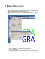
3 Basic Operations
Once the plug-in has been set up, "Cutting Master" is added to the "File" menu in
Illustrator, allowing "Settings", "Output to Plotter", "Create Registration Marks" and
"How to Print and Cut" to be selected from this submenu.
Most of the operations required for this plug-in are performed using these four menu
items.
<Settings>
Opens the plug-in setup window.
For details on these settings, see "4 Function Details."
<Output to Plotter>
Outputs to the plotter in accordance with the settings selected.
<Create Registration Marks>
Converts the selected rectangle in an Illustrator document into registration marks.
<How to Print and Cut>
Registration marks are used to enable precise cutting of printed objects. Click this
6
menu item to display a PDF file that explains the procedure.
To output to the plotter
Selecting "Cutting Master" > "Output to Plotter" in the Illustrator "File" menu
outputs the drawing in the Illustrator document to the plotter. The output position
will be to the right of and above the plotter origin.
The drawing is output so that if we imagine the smallest possible rectangle
enclosing the entire drawing, the bottom left-hand point of the rectangle corresponds
to the plotter origin. The output size will be the size of the drawing in the Illustrator
document (provided that "Use Document Origin [Default: OFF]," "Rotate," or
"Scaling" have not been altered).
To output alphanumeric characters
Only alphanumeric characters that can be converted to outlines can be output using
this plug-in, and only the outlines are output. Select the character to be output in the
Illustrator document, and use "Create Outlines" in the Illustrator "Type" menu. The
outlines created can be output in the same way as other objects.
To change the output position
The output position can be changed by specifying the desired values in the "Offset"
boxes on the Cutting Master window Options page. Note that drawings cannot be
output to the left of or below the plotter origin. Even if negative offset values are
specified, only the area of the figure to the right of and above the plotter origin will
be output.
To change the output size
The output size can be changed by entering different numeric values for the
"Scaling" function available in the Cutting Master window.
To rotate the output
The drawing to be output can be rotated by using the "Rotate" function available in
the Cutting Master window. The rotated drawing will always be output to the right
of and above the plotter origin. The drawing is output so that the bottom left-hand
point of the rectangle enclosing the entire drawing after rotation corresponds to the
plotter origin (provided "Use Document Origin" has not been altered).
To output outlines with thick lines
Outlines with thick lines can be created using the following procedure. (Save the
document first.)
1. In Illustrator, select the line to be output in the outline.
2. In the Illustrator "Color" window, set "Fill" to "/(None)."
3. Select "Object">"Path">"Outline Stroke" from the Illustrator menu. The outline
will be created with thick lines.
The outline created can be output in the same way as other objects. (Note when
saving that the document will be changed by this procedure.)
7
To output outlines of overlapping objects
Overlapping objects can be combined using the following procedure. (Save the
document first.)
1. Select all the objects to be identified as overlapping.
2. Select "Unite" in "Combine" in the Illustrator "Pathfinder" window. The
overlapping objects are combined as a single object.
The outline is output when the combined object is output. (Note when saving that
the document will be changed by this procedure.)
To output a drawing that exceeds the plotter width (Tiling)
Character outline data can be output by cutting out and closing the shape of the
boundary specified by the plotting area using the "Tiling/Overlap" functions in the
Cutting Master window.
However, it may not be possible to close the shape if the data is extremely complex
(e.g., data created by combining a number of objects or character outlines, data with
curves edited using the Illustrator "Direct Selection" tool, and data with numerous
overlapping objects or intersecting lines). In such cases, the Weed Border function
should also be used. If divided drawings are output in conjunction with the Weed
Border function, the boundaries of pages within the border are cut with straight lines.
It is also possible to divide and output drawings using the Illustrator "Knife" tool.
To divide a drawing in Illustrator before output
First of all, in the Cutting Master window Options page, set "Use Document Origin"
to OFF and "Output Selected Object(s)" to ON. The following procedure divides the
drawing. (Save the document first.)
1. Cancel the grouping for any grouped objects in the document.
2. Select "Knife" in the Illustrator toolbox, and divide the drawing into a width that
can be output on the plotter. The knife can be used to specify divisions along
straight lines by depressing the keyboard Alt key.
Select one part of the divided drawing to output. After outputting, replace the
medium, and output the other part. The procedure is the same for dividing the
drawing into three or more parts. (Note when saving that the document will be
changed by this procedure.)
To print and then cut round the print
Print & Cut applications involve a secondary process whereby a cutting plotter is
used to cut round images or shapes output on a printer. A cutting plotter equipped
with a registration mark reading unit is required for Print & Cut applications.
1. Creating registration marks
First of all, create registration marks around the printed image as follows. (Save
the document first.)
• Draw a rectangle as a standard for creating the registration marks around the
figure that is to be printed and cut.
8
• Select "Cutting Master" > "Create Registration Marks" in the "File" menu of
Illustrator with only the rectangle selected.
• Press the "Create" button on the displayed window. Illustrator then creates
registration marks. (Check the box for "Align Document Origin with
Registration Marks.")
2. Printing
Print the document, including the registration marks created in the step above,
with a printer.
3. Cutting
The following operation depends on the type of plotter you use.
<When using a plotter that supports the Registration Mark Control command*>
* See "1.2 Features" for details of the plotters that support the Registration Mark Control command.
• Select "Cutting Master" > "Settings" in the "File" menu of Illustrator.
• Check the box for "Use Registration Marks" on the "Registration Marks" page
in the displayed Cutting Master window.
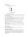
• Load the print created above ready in the plotter. Load the print in the
direction indicated in the drawing of the plotter shown in the Cutting Master
window.
• Move the pen (cutter) within the range where the bottom left of the
registration mark is readable. The readable range is the green section in the
drawing of the plotter in the Cutting Master window.
• When the document is output, the registration marks are read, and then the
printout is cut. If the registration marks cannot be read, retry reading while
pressing the "Correct Axis" button of the plotter. Cutting is started after the
registration marks are successfully read.
<When using a plotter that doesn't support the Registration Mark Control command*>
* See "1.2 Features" for details of the plotters that support the Registration Mark Control command.
• Select "Cutting Master" > "Settings" in the "File" menu of Illustrator.
• Make the following settings:
Scaling: 100%; Rotate: None; Weed Border: OFF, Tiling: OFF; Matrix Copy
(optional): OFF; Use Document Origin (optional): ON
• Compare the print with the Illustrator document. Load the print in the plotter
so that the documents bottom left registration mark (Point 1, Origin) is at the
plotter's bottom right when the plotter is viewed from the front.
• If the shape, length or thickness is inconsistent with any of the plotter settings,
change the settings of the created registration marks to ensure consistency.
• Read the registration marks with the plotter.
• When requested by the plotter, enter the distance between the registration
marks.
• Cutting starts when data is output from the Cutting Master.
9
To print and cut in alignment
Printing and cutting in alignment means arranging multiple duplicated printed
images bounded by registration marks and cutting while reading the registration
marks sequentially. This process is used for the mass production of stickers and
suchlike. To print and cut in alignment, a plotter that can handle print and cut in
alignment applications is required.
* See "1.2 Features" for details of the plotters that can handle print and cut in
alignment applications.
1. Creating registration marks
Create registration marks around the printed images using the operation given in
the previous section. (Save the document first.)
2. Printing in alignment
When using a RIP for printing, arrange the multiple printed images with
registration marks by using the allotment function of the RIP before printing. If a
RIP is not used, use the editing function of Illustrator to create multiple images
with registration marks before printing. (Multiple figures can easily be created at
equal intervals by selecting all the figures bounded by and including the
registration marks, setting the travel distance in the window displayed when
"Transform" > "Move" is selected in the Object menu of Illustrator, copying with
the Copy button, and repeating the process by holding down the Ctrl key and
pressing the D key.
3. Cutting
• Activate Cutting Master by selecting "Cutting Master" > "Settings" in the
"File" menu of Illustrator. When copying a figure in Illustrator, before
activation, select only the one block that is surrounded by registration marks
and used as the original for copying.
• Check the box for "Output Selected Object(s)" on the "Options" page of the
displayed Cutting Master window.
• Check the box for "Use Registration Marks" in the "Registration Marks" page.
• Load the print created above in the plotter. Load the print in the direction
indicated in the drawing of the plotter shown in the Cutting Master window.
• Move the pen (cutter) within the range where the bottom left registration mark
is readable in the bottom left end of the block. The readable range is the green
section in the drawing of the plotter in the Cutting Master window.
• Check the box for "Align" in the "Registration Marks" page of the Cutting
Master window.
• Specify the number of blocks to be printed in the Align text boxes. "x"
indicates the number of blocks in the horizontal direction of the Illustrator
document, and "y" the number of blocks in the vertical direction. The distance
between the blocks is the length of a blank area between the blocks.
• When the document is output, the registration marks are read, and then the print
is cut. When the output is complete for one block, the system reads the registration
marks for the next block and cuts the print. If the registration marks cannot be read,
follow the instructions displayed on the plotter panel.
10
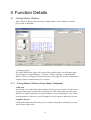
4 Function Details
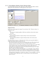
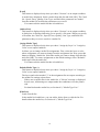
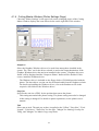
4.1 Cutting Master Window
This window is displayed by choosing "Cutting Master," then "Settings" from the
[File] menu of Illustrator.
(Changing pages)
The items shown in the upper-left section of the window allow you to change pages.
You can choose "Output Settings," "Options," "Plotter Settings," or "Registration
Marks". When you change selections, the items on the right side of the Cutting Master
window change to match what you've selected.
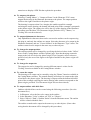
4.1.1 Cutting Master Window (Items Always Displayed)
Valid Area
Specifies the size of the black frame displayed in the preview window. Use this size as
an approximate guide to determine the output size. This setting does not affect other
functions or plotter operations except tiled output, or when using Matrix Copy. When
entering numeric values here, use the [Update Preview] button to update the preview.
Complete Preview
Changes the method by which the preview window is displayed. Normally leave this
item selected while in use.
11
Deselect this item if dialog box response slows down to update the preview window as
when outputting drawings in fine detail.
Preview Window
Displays an outline of the drawing or text to be output using blue lines.
A black border encloses the range specified in "Valid Area." The lower-left position of
the black border is always the origin specified by the plotter.
The blue lines and red borders change display position or size as offset and scaling
settings change. Use the [Update Preview] button to update the preview for
confirmation.
Update Preview
Updates the preview window as you set.
Scaling
Enlarges or reduces the document drawing size within a range of 25% to 400%. The
value specified is applied equally in both horizontal and vertical directions. Thus, for
25%, the area will be reduced to 1/16th. This setting is also reflected in the preview
window. When entering numeric values here, update the preview using the [Update
Preview] button.
Rotate
Rotates the area enclosing the drawing to be output.
If "Use Document Origin" is checked, the area enclosing the drawing to be output and
the origin of the Illustrator document is rotated.
Note that the output origin may be about 0.5 to 1 mm out of position when rotated.
This setting is also reflected in the plotter image and preview window.
Weed Border /Margin
Outputs a frame to facilitate the weeding of cut media. Using this function eliminates
the need to create a frame in Illustrator documents.
When "Weed Border" is selected, a frame is output along with the drawing when you
output the drawing to the plotter.
The "frame" here refers to a rectangular shape representing the area that encloses the
drawing to be output. The frame is expanded in the vertical and horizontal directions
by an amount equal to the size specified for Margin. When multiple drawings are to be
output, a large frame is output that includes all the drawings, and not just individual
drawings. This setting is also reflected in the preview window. When changing
numeric values, use the [Update Preview] button to update the preview.
When using this function, the drawing is output so that the lower-left position of the
frame overlaps the plotter origin. Therefore, note that the drawing output position
differs from when no frames are specified.
Selecting "Assign by Layer" or "Assign by Color" as an output condition outputs the
frame with "default*" settings.
12
When you use framing along with "Use document origin," consider the frame
margins in Illustrator documents when specifying the origin. If the frame protrudes
leftward or downward from the origin, the protruding portion is not plotted.
Tiling/Overlap
Use the Tiling function to separately output a large drawing or text (outline) which
exceeds the medium you are using on multiple pages. When Tiling is selected, Valid
Area is used as the page size. Any part of the drawing that exceeds that area is output
to the next page.
A dialog box is displayed during output, prompting you to set media over again for
each page. In this dialog box, verify the media resetting and origin position.
Specifying other than 0 for "Overlap" overlaps pages by an amount equal to the
specified width at output. Use this function to create overlapping portions for
positioning purposes while cutting.
When multiple pages are output, multiple black frames representing the valid area are
displayed in the preview window. Moreover, specifying any value other than 0 for
"Overlap" displays the overlapping valid areas by an amount equal to the specified
width. When changing numeric values, use the [Update Preview] button to update the
preview.
If the Weed Border function is turned off, all the shapes on each page are closed.
The closing operation is performed taking into account the inclusion relationship.
Note that if objects to be output on Illustrator documents have an outer border, this
will be closed as outline data if divided before outputting. Objects will not be closed
if they are not closed before dividing. Similarly, it may not be possible to close a
shape correctly if the data contains numerous overlapping objects or intersecting
lines.
If the Weed Border function is turned on, sections adjoining the page will be cut
using straight lines.
A drawing output separately on multiple pages is output sequentially toward the top
of the preview window, with the page that includes the origin considered page 1.
Any pages on the right side are also output sequentially from the bottom page
upward after the plotter has output the top page in the column that includes the
origin.
The "Tiling/Overlap" functions cannot be used simultaneously with the Matrix
Copy function.
When using divided output, select "Plotter" or "Set now" for the Output Conditions.
About
Displays the version and copyright information for the plug-in.
Repeat
Specifies the number of cuts to be made at the same location. Depending on the type of
material, cutting it once may not be sufficient. Use this function to specify additional
cuts if required.
13
[Output to Plotter]
Displays a dialog box prompting confirmation and outputs the drawing to the plotter
under the conditions you set.
If your plotter is a model that supports the Registration Mark Control command, the
"Use Registration Marks" function on the Registration Marks Page can be used. When
the checkbox has been selected, a window similar to the following is displayed.
* See "1.2 Features" for details of the plotters that support the Registration Mark
Control command.
When this window is displayed, check the location of the green section in the drawing
of a plotter shown in the Cutting Master window, and then move the blade tip within
this area as instructed. When using registration marks, also refer to the description in
subsection 4.1.5, "Cutting Master Window (Registration Marks Page)".
[Restore Defaults]
Displays a dialog box prompting confirmation. Click [OK] to initialize all settings then
displayed.
[Cancel]
Discards all that you've set and exits the Cutting Master window.
[OK]
Saves what you've set and exits the Cutting Master window.
14
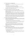
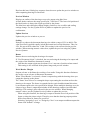
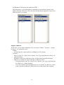
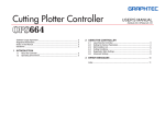
4.1.2 Cutting Master Window (Output Settings Page)
Choosing "Output Settings" in the upper-left section of the Cutting Master window
displays the items shown below on the right side of the window.
Output Selection
In this item, set the target to be output. You can choose "All," "Select by Layer," or
"Select by Color."
"All"
All objects are output regardless of the layer and object colors in the current
document.
"Select by Layer"
You can specify whether to output each layer in the current document.
"Select by Color"
You can specify whether to output each object (line) color in the current
document.
Choosing "Select by Layer" or "Select by Color" allows you to specify whether to
output each instance double clicked in the list.
The current document refers to the one positioned at the top of the currently open
Illustrator documents immediately before invoking this plug-in software.
Choosing "Select by Color" allows selections to be made with respect to the outline
colors of objects in the current document. Objects whose outline colors are
unspecified are not displayed in the list and excluded from the target to be output.
The "fill" colors of objects are ignored.
When creating a new document in Illustrator 9, 10, CS and CS2, you are asked to
determine whether the object colors should be handled in RGB or CMYK. In this
plug-in software, the outline colors of objects are displayed in the list according to
that specification. Regardless of whether you choose "Convert to RGB" or "Convert
to CMYK" from the Illustrator menu, your specification is not reflected in this
plug-in software.
15
All Illustrator 8 documents are handled in RGB.
With Illustrator 8, color information for drawings not selected may appear in the
Output Selection: Select by Color color lists, but this may be ignored, as it does not
affect the preview or output.
Output Conditions
In this item, you set output conditions. You can choose "Plotter", "Set now", "Assign
by Layer", or "Assign by Color."
"Plotter"
All drawings are output under the conditions set in the plotter.
"Set now"
Specify Cond. No., Speed, Force, Quality, Line Type, and Pitch Size before you
output drawings.
Regardless of the layer and object colors in the current document, all target
objects to be output are output under the conditions set here.
For details about Cond. No., Speed, Force, Quality, Line Type, and Pitch Size,
see Section 4.3, "Media Settings."
You can do without specifying Speed, Force, or Quality. In such case, set the
value 0 for these parameters. What is then set on the plotter side is applied.
16
"Assign by Layer," "Assign by Color"
"Assign by Layer" allows you to assign media files (one for each layer). "Assign
by Color" allows you to assign media files (one for each color in the drawing).
Initially, all media files are assigned "" to indicate that drawings are output under
the media file conditions specified in "Default" media type. Use the [Assign
Media Type] button to change assignments.
"Assign by Layer" can only be used when "Select by Layer" is specified for
the target to be output.
"Assign by Color" can only be used when "Select by Color" is specified for
the target to be output.
Media files are setup files in which such standard parameters such as Cond.
No., Speed, Force, and Quality are assigned for each type of media.
When using divided output, select "Plotter" or "Set now" for the Output
Conditions.
17
18
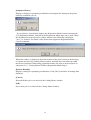
[Load]
This button is displayed only when you chose "Set now" as an output condition.
A media list is displayed. Select a media from this list and click [OK]. The Cond.
No., Speed, Force, Quality, Line Type, and Pitch Size parameters are loaded
from the media file in which the parameters were saved.
You cannot edit the media list that is loaded here.
[Add to List]
This button is displayed only when you chose "Set now" as an output condition.
A dialog box is displayed allowing you to specify a file name. When you specify
a file name, the Cond. No., Speed, Force, Quality, Line Type, and Pitch Size
parameters that you set are saved to a media file.
[Assign Media Type]
This button is displayed only when you chose "Assign by Layer" or "Assign by
Color" as an output condition.
It allows you to change media file assignments. First, select the layer or color
whose assignment you want to change from the assignment list. Next, press this
button to display a media list. Select the media you want to change from this list
and click [OK]. To restore assignments to the default settings, select "Default*"
media type from the media list.
You cannot edit the media list that is loaded here.
Default Media Type (*)
This button is displayed only when you chose "Assign by Layer" or "Assign by
Color" as an output condition.
The layers and colors marked "*" in the assignment list are output according to
the media file settings selected here.
If there are no media files in the media list, a "Not set" message is displayed.
In such case, all drawings are output under the conditions set on the plotter
side.
For details about the media list, see Section 4.2, "Media Type List."
[Edit List]
Loads a media list.
In the media list loaded here, you can add to, delete from, or edit the list. For
details about the media list, see Section 4.2, "Media Type List."
19
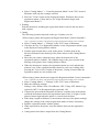
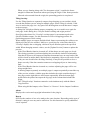
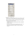
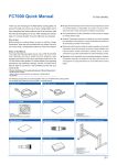
4.1.3 Cutting Master Window (Options Page)
Choosing "Options" in the upper-left section of the Cutting Master window displays
the items shown below on the right side of the window.
Sort Objects
Sets the order in which objects are output. The display varies depending on whether
you choose "Flatbed Type" or "Friction Feed Type" on the plotter setup page of the
Cutting Master window.
For Friction Feed Type, you can use all choices available. For Flatbed Type, you can
use "None," "Speed priority (by layer)," or "Speed priority (All)".
Irrespective of the settings you make below, objects whose end points coincide are
sorted for plotting with one stroke of a pen as much as possible.
"None"
The output order is not changed.
"Speed priority (by layer)"
By recognizing the layers to which each target object belongs, objects are sorted
in order of pen movements in each layer, beginning with the object with the least
pen movement. Each layer is output in order of Illustrator's layer palettes.
"Speed priority (All)"
By ignoring layers, all target objects to be output are sorted in order of pen
movements, beginning with the object with the least pen movement, and are then
output.
"Restrict media movement (by layer)"
By recognizing the layers to which each target object belongs, objects are sorted
in order of media movements in each layer, beginning with the object with the
least media movement. Each layer is output in order of Illustrator's layer palettes.
20
"Restrict media movement (All)"
By ignoring layers, all target objects to be output are sorted in order of media
movements, beginning with the object with the least media movement.
Use Document Origin
When unchecked, the drawing is output so that the bottom left-hand point of the area
enclosing the drawing corresponds to the plotter origin. When checked, the drawing is
output so that the origin of the Illustrator document corresponds to the plotter origin
(maintaining the actual position of the drawing from the document origin). Note that
areas to the left of or below the plotter origin will not be output.
Here, "Document Origin" refers to the "Ruler origin" in the Illustrator document.
Offset
Specify to output with an offset from the origin specified for the plotter. Negative
values can be specified, but areas to the left of or below the plotter origin will not be
output. When changing numeric values, use the [Update Preview] button to update the
preview.
Output Selected Object(s)
When checked with any object selected in an Illustrator document, only that object
becomes the target to be output. When no objects are selected, all displayed objects
become targets to be output.
When unchecked, all displayed objects become targets to be output regardless of
whether any object is selected in an Illustrator document.
This setting overrides "Output Selection" settings made in the Cutting Master
Window (Output Settings Page). The objects not meeting the conditions of this
setting are not displayed in the "Output Selection" list of the Cutting Master
Window (Output Settings Page).
Output Hidden Layer(s)
When checked, objects on hidden layers are output in addition to those on layers
displayed in the Illustrator document. Note that objects on hidden layers will all be
treated as not selected, so they will not be output if there are objects selected with
"Output selected object(s)" checked.
This setting overrides "Output Selection" settings made in the Cutting Master
Window (Output Settings Page). The objects not meeting the conditions of this
setting are not displayed in the "Output Selection" list of the Cutting Master
Window (Output Settings Page).
Feed Medium
Sets how the media should be handled after the plotter has completed output. The
display varies depending on whether you choose "Flatbed Type" or "Friction Feed
Type" in the Cutting Master Window (Plotter Settings Page).
21
<For Friction Feed Type>
If the Feed Medium checkbox has been selected, you can choose "From the End
Point" or "From the Origin" and specify the feed length. You can also choose to
perform cross cutting by selecting the Cross Cut checkbox.
The "From the End Point"/"From the Origin" selection and the feed length
specification are only effective when using roll paper.
If you select the Feed Medium checkbox when using roll paper, the plotter operates
in the manner described below.
"From the End Point"
Paper is fed by the specified length with respect to the maximum X position used
at output, and the origin is moved to the X position at which the plotter
completed the feed operation. The Y position of the origin is not moved.
"From the Origin"
Paper is fed by the specified length with respect to the origin, and the origin is
moved to the X position at which the plotter completed the feed operation. The Y
position of the origin is not moved.
Cross Cut
If the Cross Cut checkbox is selected, the paper is cut off from the roll after it has
been fed. (This setting will be ignored for models that do not have a built-in cross
cutter).
If you select the Feed Medium checkbox when using sheet (cut) paper, the pen
carriage is moved to the standby position after the plotter has output all the drawings,
and the plotter prompts you to change media after feeding the paper through to the
end.
<For Flatbed Type>
Only the Feed Medium checkbox is displayed.
When this checkbox is selected, the pen carriage is moved to the standby position
after the plotter has output all the drawings, and the plotter prompts you to change
media.
Matrix Copy
Check the box to do an output of an arrangement of multiple figures.
When this checkbox is selected, the target drawing to be output is copied for x rows in
the horizontal direction (rightward) and y lines in the vertical direction (upward) before
being output. You can specify arrangement intervals in both the horizontal and vertical
directions.
The range specified for Valid Area (i.e., black frame in preview window) limits the
total output size derived from copying.
Multiple copies of the target drawing to be output are also displayed in the preview
window according to this setting. When changing numeric values, use the [Update
Preview] button to update the preview.
The Matrix Copy function cannot be used simultaneously with the Tiling/Overlap
functions.
22
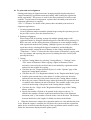
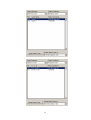
4.1.4 Cutting Master Window (Plotter Settings Page)
Choosing "Plotter Settings" in the upper-left section (changing pages) of the Cutting
Master window displays the items shown below on the right side of the window.
Output to
Select the Graphtec Windows driver to be used from among those installed in the
system. The "Port" set for the driver selected is used as the output destination. If the
Graphtec Windows driver has not been installed in the system, "Graphtec driver not
found" will be displayed and the "Output to Plotter" button will be disabled. If this
occurs, install the Windows driver.
The Windows driver is included on the floppy disk or CD-ROM provided with the
plotter. The latest driver version can also be downloaded from the Graphtec website.
For details on installing the Windows driver, refer to the Readme.txt file in the
respective OS folder for the Windows driver.
Step Size
Specifies the unit size (GDU) for the position data sent to the plotter.
This setting must match the plotter setting. The plotter setting must also be changed
if this setting is changed. For details on plotter operations, see the plotter's user's
manual.
Unit
Select mm or inch. The unit you set here is applied to the "Offset," "Step Size," "Feed
Length," "Valid Area," "Pitch Size" for line type, "Margin" for framing, Overlap for
Tiling, and "Margins" for Matrix Copy setup items.
23
Flatbed Type/Friction Feed Type
Selects the type of cutting plotter to be used.
[Folder Settings]
Displays a Folder Settings dialog box, allowing you to set up the folder to manage the
media list.
For details about the Folder Settings dialog box, see Section 4.4, "Folder Settings."
[Save/Load]
This button lets you save settings you've made in this plug-in software to a file and
load those settings from the file when necessary.
24
4.1.5 Cutting Master Window (Registration Marks Page)
All the items in the Registration Marks Page are functions that control the registration
mark reading unit in the plotter. A registration mark is the alignment mark that is used
to align the cutting positions on a plotter with the printed output of a printer.
Note: The functions on this page can only be used with plotters that support the
Registration Mark Control command. For all other plotter models, ensure that the
"Use Registration Marks" checkbox is unchecked.
* See "1.2 Features" for details of the plotters that support the Registration Mark
Control command.
When "Registration Marks" is selected in the page switching box at the top left corner
of the Cutting Master window, the following items are displayed on the right side of
the window.
Use Registration Marks
Check this box to enable the functions of the registration marks page. However, the
items that are normally displayed are disabled and cannot be changed. These items
include Scaling, Rotate, Weed Border, Tiling, and the optional Matrix Copy. Optional
items, such as Use Document Origin, remain enabled.
When "Use Registration Marks" is selected, before clicking the Output to Plotter
button, move the pen within the readable range of the bottom left registration mark on
the plotter medium. The bottom left registration mark is the mark that is located at the
bottom left on the Illustrator document. The readable range is the green section shown
in the drawing of the plotter displayed in the Cutting Master window.
25
Number of marks
Set the mode for reading the registration marks.
For 2, or two registration marks, the bottom left and bottom right registration marks of
the document are read.
For 3, or three registration marks, the bottom left, bottom right and top left registration
marks of the document are read.
For 4, or four registration marks, the bottom left, bottom right, top left and top right
registration marks of the document are read.
For Area, the bottom left, bottom right, top left and top right registration marks of the
document are read. The "Align/Distance between Blocks" function cannot be used
when "Area" has been specified.
Specifying a small number of registration marks speeds up the registration mark
reading operation, while the reading of several marks enables a higher degree of
correction.
Note: The "Number of marks: Area" setting can only be used with plotters that are
capable of performing segment area correction. Do not specify the Area setting for any
other plotter models.
* See "1.2 Features" for details of the plotters that are capable of performing segment
area correction.
Media Loading Direction
Select Normal or Rotate. Load the medium by referring to the drawing of a plotter
shown in the Cutting Master window.
Align/Distance between Blocks
When multiple images bounded by registration marks have been printed, the reading of
registration marks and the cutting operation are repeated according to the number
specified in this item. "x" indicates the number of blocks in the horizontal direction of
the Illustrator document, and "y" the number of blocks in the vertical direction.
The distance between blocks refers to the travel distance to the next block, ignoring
registration marks.
26
This function cannot be used when “Area” has been specified for “Number of marks”.
Correct
This function controls all of the alignment functions using registration marks. Set the
distance between the registration marks on the Illustrator document in the associated
box for entering numerical values. The set numerical values are sent to the plotter at
output. Keep this function enabled in normal operation.
If this function is disabled, the registration marks are only used for positioning and axis
alignment.
When this function is enabled, the following correction is carried out using the
registration marks.
For Number of marks 2:
Scale the coordinate system on the plotter up or down so that the distance between
the bottom left and bottom right registration marks (which are read with the
registration mark reading unit) is aligned with the numerical value of x in this item.
(Correction of the horizontal distance)
For Number of marks 3:
Scale the coordinate system on the plotter up or down so that the distance between
the bottom left and bottom right registration marks is aligned with the numerical
value of x in this item, and so that the distance between the bottom left and top left
registration marks is aligned with the numerical value of y in this item. The
distances are read with the registration mark reading unit. (Correction of the vertical
and horizontal distances)
For Number of marks 4:
Correct the coordinate system within the range between all of the positions (bottom
left, bottom right, top left and top right) read with a registration mark reading unit
and all the positions (bottom left, bottom right, top left and top right) in the data
calculated based on the numerical values of x and y in this item, taking account of
distortion. (Correction at four points)
For Number of marks: Area:
This setting is effective when cutting a design that is extremely long in the media
feed direction (as a guideline, a design that is longer than 3 m). Intermediate
registration marks are used as boundary points for dividing the design up into
multiple areas. 4-point correction is then performed for each area. This function
enables even more accurate correction of media skew or other alignment problems
that occurred when the design was printed (segment area correction).
Load the design in the plotter so that the intermediate registration marks are in
the plotter's media feed direction. Intermediate registration marks in the cutter
movement direction will not be read.
Unlike drafting units, few printer types guarantee precision in the dimensions for
the printing position. Distance correction and correction at the four points are
operations that adjust the coordinate system of the plotter according to the printed
results so that the printing positions and cutting positions are as closely aligned
as possible. These operations usually improve the cutting positions. To ensure
higher precision when adjusting the cutting positions, it is recommended that you
use a precision-guaranteed ink-jet plotter or suchlike instead of a printer.
27
Generally, laser printers are less precise than ink-jet printers. In particular,
distortion may occur when using sheet paper with a laser printer due to paper
skew. Accordingly, it is difficult to obtain good results when using such a device
for printing and cutting.
"Auto-Correct"
When registration marks are created with the registration mark creation function
provided with Cutting Master, the distance between the created registration marks is
automatically set as the distance in the data in the box for entering numerical values.
"Size Specified"
Manually enter the distance between the registration marks in the document in
the numerical value input box. This function should be used when registration
marks are not created using the registration mark creation function in Cutting
Master, or when you wish to change the distance between the registration marks.
Send Registration Mark Conditions
When registration marks are created using the registration mark creation function in the
Cutting Master, the shape, length and thickness of the created registration marks are
sent to the plotter. This function should be enabled in normal operation.
28
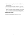
4.2 Media Type List
Use this list to manage the media files in which you saved the output conditions.
Settings list
Media names (media file names) and the settings saved in those files are displayed in
list format.
The media files initially displayed in the setting list after setups are provided as an
approximate guide for your reference. The settings displayed here are not
guaranteed to be appropriate. The actual optimum settings differ with the make, type,
and purpose of use of each media used. The settings also change due to abrasion of
the cutter blade and other changing conditions. Determine optimum settings by
using the trial plotting function available on the plotter, then modify settings in or
add settings to the list.
[Create]
Launches a Media Settings dialog box allowing you to make media settings. Click
[OK] to exit the Media Settings dialog box. A new media file is then created.
You cannot create media using an existing media name in the setting list.
For details about the Media Settings dialog box, see Section 4.3, "Media Settings."
[Copy]
Pressing this button after selecting a medium from the setting list opens a Media
Settings dialog box using the settings for the medium selected. Change the media name
in this dialog box and save it. A new media name is then created.
For details about the Media Settings dialog box, see Section 4.3, "Media Settings."
[Modify]
Pressing this button after selecting a medium from the setting list opens a Media
Settings dialog box.
For details about the Media Settings dialog box, see Section 4.3, "Media Settings."
29
[Delete]
Deletes the media selected in the setting list.
[Load]
Loads a media settings file in which the standard settings (for each type of plotter used
and each purpose of media use) are saved. This file is added to the media list.
30
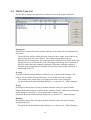
4.3 Media Settings
Create or modify the output conditions for each media type.
Name
The current media name is displayed here. Any desired media name can be specified.
Media names of up to 27 characters (single-byte characters) can be entered.
Cond. No.
Specifies the plotter condition setting number. Valid numbers range from 1 to 8, but
numbers that cannot be set on the plotter should not be specified. (Some plotters cannot
specify numbers 5 to 8.)
Speed
Specifies the pen speed on the medium for cutting or plotting. Available speeds range
from 0 to 100, but the optimum setting will vary depending on the media and pen type.
Likewise, the values that can be set will vary depending on the plotter. For details, see
the plotter's user's manual. Specifying "0" deselects the setting, and the speed for the
"Cond. No." specified above is used.
Force
Specifies the force applied to the pen for cutting or plotting. This setting is only valid
when specified together with "Quality." The value for Force can be set from 0 to 100,
but the optimum setting will vary depending on the media and pen type. Likewise, the
values that can be set will vary depending on the plotter. For details, see the plotter's
user's manual. Specifying "0" deselects the setting, and the force for the "Cond. No."
specified above is used.
31
Quality
Specifies the pen acceleration for cutting or plotting. Specifying lower values increases
the quality. This setting is only valid when specified together with "Force." Valid
Quality settings range from 0 to 10, but the optimum setting will vary depending on the
media and pen type. Likewise, the values that can be set will vary depending on the
plotter. For details, see the plotter's user's manual. Specifying "0" deselects the setting,
and the quality for the "Condition No." specified above is used.
Line Type
The line type to be output can be selected from the list of solid lines, dotted lines,
dashed lines (3 types), dotted/dashed lines (2 types), and double-dotted/dashed lines (2
types). Solid lines should be used for normal cutting.
Pitch Size
This is only available when a line type other than solid is selected. Lines other than
solid are formed from the repeated specified patterns. Pitch size specifies the length of
the pattern.
32
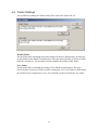
4.4 Folder Settings
Set up folders to manage the media setting files used in the media list, etc.
Default Folder
Set the folder here containing the media setting files that are displayed by pressing the
[Load] button in the Media List dialog box. Press the [Select] button to choose a folder
from the ensuing list. You normally need not modify the default media folder.
User Folder
Set the folder here containing the settings of the Media List dialog box. Press the
[Select] button to choose a folder from the ensuing list. Use User Folder to differentiate
the media list for each purpose of use. You normally need not modify the user folder.
33
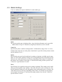
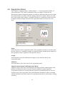
4.5 Registration Marks
This window is displayed when "Cutting Master" > "Create Registration Marks" is
selected from the "File" menu in Illustrator while a rectangle is selected in an
Illustrator document. Registration marks are marks for alignment that are used to align
the printed results of a printer with the cutting positions by a plotter. When you click
the Create button in this window, registration marks are created based on the selected
rectangle and the rectangle is deleted. The registration marks are created in a new
layer.
Shape
Select the pattern for the registration marks. The registration marks are created so that
the four corners of a standard rectangle are aligned with the standard points (angles) of
the registration marks, regardless of the pattern selected.
Length
Set the distance from the standard point (angle) to the end of the line for the
registration marks.
Thickness
Set the thickness of the lines used for the registration marks.
Align Document Origin with Registration Marks
Align the origin of the ruler in the Illustrator document with the standard point of the
bottom left registration mark. Keep this function enabled in normal operation.
If registration marks were created when this function was disabled (the box was not
checked), move the origin of the ruler in the Illustrator document so that it is aligned
with the standard point of the bottom left registration mark before performing a cutting
operation.
34
Create in 5-mm Increments
When the size of the standard rectangle is not a multiple of 5 mm, creates the
registration marks after increasing the size of the rectangle until it becomes a multiple
of 5 mm.
Distance between Standard Points
Displays the distance between the registration marks when the registration marks are
created with the current settings.
Intermediate Registration Mark
Creates intermediate registration marks for use during segment area correction. Use
this function when cutting extremely long designs (as a guideline, designs that are
longer than 3 m). If "Area" has been specified for "Number of marks" in the Cutting
Master "Registration Marks Page", segment area correction is performed during the
cutting operation.
The Intermediate Registration Mark function can only be used with plotters that are
capable of performing segment area correction. Do not specify this setting for any
other plotter models.
* See "1.2 Features" for details of the plotters that are capable of performing segment
area correction.
Media Feed Direction
Using the Illustrator document design as a reference, specify the direction in which the
media is going to move for cutting. The registration marks are created in the specified
direction.
Step
Specifies the interval at which the intermediate registration marks are placed. The
optimal value varies according to factors such as the quality of the media and the media
feed accuracy of the device used to print the design. Normally, specify an interval of at
least 1 m in length. In general, if the specified value is smaller than the width of the
medium in the cutter movement direction, the accuracy will not be improved.
Moreover, the larger the number of intermediate registration marks, the longer it will
take for registration mark reading when cutting is performed.
[Create]
Creates the registration marks based on the settings and erases the standard rectangle.
The registration marks are created in a new layer and are locked.
CAUTION
Do not move the Illustrator document origin after registration marks have been created.
35
5 Error Messages
No output objects found.
No vector data exists in the document (including when text is not outlined).
→ Convert a graphic object containing text into outline format.
The "Output selection" setting in the Cutting Master window (Output page) is set
to "Select by Layer" or "Select by Color," and no layers or colors are set to be
output (Plot: No).
→ Set the layers or colors to be output to "Plot: Yes."
Deselecting the Output Hidden Layer(s) checkbox of Cutting Master hides all
layers in Illustrator.
→ Turn on the display of the layers to be output.
A Graphtec Plotter Driver could not be found.
The Windows driver has not been installed.
→ This plug-in software outputs via the Windows driver. Windows driver must
be installed.
* Windows driver is included on the floppy disk or CD-ROM provided with
Graphtec plotters, except for some older models. The latest driver version can
also be downloaded from the Graphtec website. For details on installing
Windows driver, refer to the Readme.txt file in the respective OS folder for
Windows driver.
The specified Graphtec Plotter Driver could not be found.
The Windows driver used previously has been deleted.
→ This plug-in software outputs via the Windows driver. Reselect the output
destination for "Output to" in the Cutting Master window (Plotter Setup page).
Install Windows driver if it is not already installed in the system.
* Windows driver is included on the floppy disk or CD-ROM provided with
Graphtec plotters, except for some older models. The latest driver version can
also be downloaded from the Graphtec website. For details on installing
Windows driver, refer to the Readme.txt file in the respective OS folder for
Windows driver.
No media files could be found.
The media list has been completely deleted.
The default media folder or media folder in the Folder Setup window has been
changed to a folder containing no media files.
→ No problems will be caused if "Assign by Layer" and "Assign by Color" are
not used in Output Conditions.
If "Assign by Layer" or "Assign by Color" is used, either create or add media
in the media list. Alternatively, change the Default Folder or User Folder to
the original folder used when Cutting Master was first installed in the Folder
Setup window.
36
The selected media type name already exists. Overwrite?
A media type name saved previously was selected when a media type was added
to the media list.
→ Selecting "Yes" overwrites the selected data saved in the media list. Selecting
"No" changes the data to be added before it is saved in the media list.
Selecting "Cancel" aborts the adding of the media type name.
The file type does not match. This file could not be loaded.
An attempt was made to load an incorrect settings registration file.
→ Only settings registration files saved using this plug-in can be used. Specify a
file saved using this plug-in software.
Too large. Please re-specify the Matrix Copy plotting area.
Matrix Copy is improperly set.
→ Matrix Copy can only be used in a specified plotting area (Valid Area).
Confirm that the settings you made are correct.
A file operating error has occurred.
An attempt was made to output to or save settings over the file currently being
used by another application.
→ Assign the file another name before you output or save it.
37
The specifications, etc., in this manual are
subject to change without notice.
OPS640W-UM-158
September 2, 2005
1st edition-02
GRAPHTEC CORPORATION