1
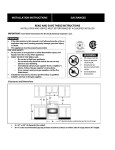
Solid fuel boiler for
central heating
STROPUVA
TECHNICAL PASSPORT
INSTALLATION AND MAINTNCE
INSTRUCTIONS
TECHNICAL PASSPORT INSTALLATION AND MAINTENANCE INSTRUCTIONS
Contents
1. TECHNICAL SPECIFICATIONS....................................................................................... 3
1.1 MAIN TECHNICAL SPECIFICATIONS........................................................................... 3
2. STRUCTURE OF BOILER ............................................................................................... 5
2.1 DESCRIPTION OF BOILER STRUCTURE.................................................................... 6
3 PARTS OF BOILER ...........................................................................................................6
3.1 AIR INJECTION COLLECTOR (Figure 2) ...................................................................... 6
3.2 AIR DISTRIBUTOR WITH BURNING CHAMBER STABILIZER ................................... 7
3.3 FIRE GRATE (Figure 4).................................................................................................. 8
3.5 DEFELCTORS (Figure 5) ............................................................................................... 8
3.5 FLUE RING (Figure 6) .................................................................................................... 9
3.6 SAFETY VALVE (1.5 BAR) ............................................................................................. 9
4. TRANSPORTING AND STORAGE ................................................................................ 10
5. INSTALLATION OF BOILER .......................................................................................... 10
5.1 FIREFIGHTING REQUIREMENTS .............................................................................. 10
5.2 FLUE REQUIREMENTS .............................................................................................. 10
5.3 REQUIREMENTS FOR CONECTING TO HEATING SYSTEM ................................... 11
6. DIAGRAM OF HEATING SYSTEM ................................................................................ 12
6.1 DESCRIPTION OF DIAGRAM OPERATION (Figure 8)............................................... 13
6.2 diagram of connecting ,,Stropuva” boiler to other boiler, water heater and floor
heating ................................................................................................................................14
6.3 diagram of connecting ,,Stropuva” boiler to other boiler, water heater, radiators
and floor heating .................................................................................................................15
6.4 diagram of connecting ,,Stropuva” boiler to other boiler, water heater, radiators ......... 16
7. FIRING OF BOILER AND ADDING FUEL ...................................................................... 17
7.1 FUEL IN BOILER BURNS MOST EFFICIENTLY ......................................................... 17
7.2 RECOMMENDATIONS FOR FIRING OF UNIVERSAL BOILER ................................ 18
7.3 SETTINGS OF DRAFT REGULATOR (Figure 13) ....................................................... 19
7.4 ASSESMENT OF BOILER OPERATION ..................................................................... 19
8. REQUIREMENTS OF SAFETY EQUIPMENT ............................................................... 20
7.5 CLEANING AND MAINTENANCE OF BOILER ........................................................... 20
9. RISK ASSESSMENT ......................................................................................................21
9.1 DANGERS OF HEAT ...................................................................................................21
9.2 DANGERS OF PRESSURE ......................................................................................... 22
9.3 POSSIBLE POISONING .............................................................................................. 22
9.4 REQUIRMENTS FOR CONECTING ELETRICAL PART ............................................. 22
10. ATTACHEMENTS .........................................................................................................22
10.1 ELECTRONICAL CONTROLLER .............................................................................. 22
10.2 PELLET BURNER ......................................................................................................24
11. PACKAGE CONTENT ..................................................................................................25
12. WARANTY CONDITIONS OF PRODUCT ................................................................... 25
13. WARRANTY CERTIFICATE ......................................................................................... 26
2
TECHNICAL PASSPORT INSTALLATION AND MAINTENANCE INSTRUCTIONS
ATTENTION! Before installing and using this boiler please read this instruction carefully.
It will help you install it correctly and use it effectively as possible also to prevent possible
accidents.
1. TECHNICAL SPECIFICATIONS
Solid fuel water heating boilers “Stropuva” (further on – boiler) are designed for heating of
premises with central heating system, radiators, boiler for heating of water for household or
floor coil-pipe or heater or all the mentioned. System can have natural or forced circulation.
System can use open or closed system. Boiler is sold with draft regulator, which is patented by
our company.
“STROPUVA” produces three types of boilers:
•For firewood (firewood);
•“U” universal (firewood, coal, peat and sawdust briquettes, pellets, wood chips) ;
•“BIO” (firewood, sawdust briquettes, pellets, wood chips);
and four different capacities 7 kW; 10kW; 20 kW; 40 kW. Boilers “STROPUVA” can be used
to heat premises with from 20 to 400 m2 of heated space.
1.1 MAIN TECHNICAL SPECIFICATIONS
Used fuel: firewood, wood residues, sawdust briquettes, peat briquettes, coal and pellets.
Recommended dampness of fuel up to 30 %
Model of boiler
S7
S10
S20
S40
S7
BIO
S10
BIO
S20
BIO
S40
BIO
S10
U
S20
U
S40
U
Power (kW) *
7
10
20
40
7
10
20
40
10
20
40
Heated space ( m2) **
20-70
50-100
20-70
50-100
Fuel capacity (dm3)
90
150
210
360
90
150
210
360
135
230
320
Maximum amount of firewood (kg)
15
25
50
80
15
25
50
80
25
50
80
Maximum amount of pellets (kg)
-
-
-
-
50
80
130
220
80
130
220
Maximum amount of briquettes (kg)
-
-
-
-
20
30
60
100
30
60
100
Maximum amount of coal(kg)
-
-
-
-
-
-
-
-
75
130
220
28
5,6
31,5
6,1
31,5
6,1
31,5
6,1
28
5,6
31,5
6,1
31,5
6,1
31,5
6,1
31,5
6,1
31,5
6,1
31,5
6,1
-
-
-
-
50
10
72
14
72
14
72
14
72
14
72
14
72
14
Duration of burn with one load of
firewood, h. Min. mode.
(according to laboratory tests) Max.
mode. ***
Duration of burn with one load of
briquettes, h. Min. mode.
(according to laboratory tests) Max.
mode. ***
100-200 200-400
100-200 200-400
50-100
100-200 200-400
3
TECHNICAL PASSPORT INSTALLATION AND MAINTENANCE INSTRUCTIONS
Model of boiler
S7
S10
S20
S40
S7
BIO
S10
BIO
S20
BIO
S40
BIO
S10
U
S20
U
S40
U
Duration of burn with one load of
pellets, h. Min. mode.
(according to laboratory tests) Max.
mode. ***
-
-
-
-
72
14
96
24
96
24
96
24
96
24
96
24
96
24
Duration of burn with one load of coal,
h. Min. mode.
(according to laboratory tests) Max.
mode. ***
-
-
-
-
-
-
-
-
130
32
130
32
130
27
Length of firewood (cm)
35
35
45
55
35
35
45
55
35
45
55
Water amount in boiler ( l )
15
22
40
52
15
22
40
52
22
40
52
Efficiency (%)
86,3
86,3
86,3
86,3
86,3
86,3
86,3
86,3
86,8
86,8
86,8
Installed pressure protection valve (bar)
1,5
1,5
1,5
1,5
1,5
1,5
1,5
1,5
1,5
1,5
1,5
Flue draft (Pa)
10÷20
10÷20
10÷20
10÷20
10÷20
10÷20
10÷20
10÷20
10÷20
10÷20
10÷20
Flow of heated water max. (l/h)
200
250
500
1000
200
250
500
1000
250
500
1000
Water temperature inside of boiler (0C)
85
85
85
85
85
85
85
85
85
85
85
Minimum width of flue opening (cm2)
150
200
250
330
150
200
250
330
200
250
330
Diameter of flue (mm)
160
180
180
200
160
180
180
200
180
180
200
Distance from the bottom of boiler to
flue (mm)
991
1413,5
1550
1549
991
1413,5
1550
1549
1494
1673,5
1664
(1900)
(1900)
(1900)
(1900)
(1900)
(1900)
1330
1900
2100
2100
1330
1900
2100
2100
1900
2100
2100
450
450
560
680
450
450
560
680
450
560
680
100
185
231
315
100
185
231
315
196
246
333
Dimensions, (mm)
h
d
Weight (kg)
*Power depends on quality of fuel. Power depends on time: at the beginning of burning
power output is higher than indicated in a table, boiler puts out the smoke that is hotter than
300 0C, therefore raisin residues burn out, flue gets warmed up and draft increases (in some
models, direct channel to flue is opened). While fuel burns, power of boiler decreases, because
the surface of heat dissipation increases and draft decreases, but when a house becomes warm
the power is sufficient and additional valve is opened in order to further decrease the power of
boiler.
4
TECHNICAL PASSPORT INSTALLATION AND MAINTENANCE INSTRUCTIONS
**Power of boiler is selected according to heated space. For example if in Stropuva S20
solid fuel boiler built in 200m2 building one fuel load burns 24 hours than one load of firewood in
Stropuva S40 solid fuel boiler burns almost for 48 hours (35-40 hours). Solid fuel boiler Stropuva
S10 could be used, but warming up of building would take longer and fuel load would need to
be added 2-3 times in 24 hours.
***Duration of burn of one load depends on the quality of fuel, inside and outside temperature,
thermal resistance, boiler power, adherence to recommendations of user manual (boiler
installation, flow of heated water, maintenance of water temperature).
2. STRUCTURE OF BOILER
1. Air valve
2. Draft regulator
3. Support rod
4. Air heating chamber
5. Smoke removal opening
6. Switch valve
7. Telescopic pipe of air injection
8. Door for loading of fuel
9. Air distributor with combustion chamber
stabilizer
10. Fuel
11. Door for ash removal
12. Lifting cord with ring
13. Hook
14. Pipe of hot water
15. Pipe of return water
pav.1
16. Socket for thermometer
17. Socket for pressure safety valve 1,5 bar
18. Bottom
19. Fire grate
20. Deflectors
21. Air injection collector
Figure 1
ATENTTION! It is forbidden to change the construction of boiler.
5
TECHNICAL PASSPORT INSTALLATION AND MAINTENANCE INSTRUCTIONS
2.1 DESCRIPTION OF BOILER STRUCTURE
Boiler is cylinder made of steel, enveloped in a cylinder of steel of bigger diameter and this
whole construction is thermally insulated. Heated water resides between these two cylinders.
At the front part of boiler there is draft regulator (2) (more information in 7.3). Construction has
openings for loading of fuel (8) and removal of ashes (11) as well as flue for smoke removal
(5). Also there are openings for water supply pipe (14 – 15), thermometer (16) and pressure
safety valve (17). At the top part of combustion there is air pre-heating chamber (4) chamber for
enhancement of burn quality and heat transfer. Telescopic air supply pipe (7) for attaching air
distributor and combustion chamber stabilizer, fits into this chamber (9).
“U” boiler is designed for peat briquettes or coal; it has switching valve (6) and is supplied
with fire grate (19) and air injection collector (21).
“BIO” boiler is designed for firewood, pellets, and sawdust briquettes or wood chips. It is
supplied with fire grate (19) and air injection collector (21).
At the upper part of chamber there is opening for air and air valve (1). On the right side of
the boiler, in front of the door, there is a cord and ring (12) for lifting of air supply mechanism
and fixation hook (13).
Purpose of air distributor with stabilizer of combustion chamber (9) is to distribute air
correctly into generation zones, which are under and besides the air distributor, also in
burning zones. Air distributor with combustion chamber stabilizer (9) rests on firewood
which is on the sides and is not reaching high temperatures.
Distributor with stabilizer of combustion chamber (9) shouldn’t be moved during the burning:
if air distributor is lifted and lowered again, it rotates and falls deep into point of burning, than
boiler operates inefficiently and the lifespan of its parts is shortened.
3 PARTS OF BOILER
3.1 AIR INJECTION COLLECTOR (Figure 2)
With pellets, briquettes, damp firewood or other wood fuel and its residues we recommend
to use air injection collector. Air injection collector is mandatory when burning coal and peat. “U”
and “BIO” models come with air injection collector.
Air injection collector is plugged into electrical network after igniting the boiler and closing
the door.
Figure 2
6
TECHNICAL PASSPORT INSTALLATION AND MAINTENANCE INSTRUCTIONS
3.2 AIR DISTRIBUTOR WITH BURNING CHAMBER STABILIZER
(Figure 3)
Burning chamber stabilizer is mounted (fig. 3), on the smallest part of telescopic air supply
pipe (7) (fig. 1), it is integral in new boilers. We also developed units for repairs that consist of
two parts. If telescopic air supply pipe (7) (fig. 1) has three holes, then stabilizer is locked in third
hole with a pin, if it has only one hole, additional hole must be drilled 55mm from the existing
hole. After mounting the stabilizer, air distributor can be mounted (fig. 3). When burning pellets,
small firewood, distributor must be mounted on middle hole, so that space between the end of
air supply pipe (7) (fig. 1) and distributor would be reduced to 5 – 7 mm.
A) We recommend using distributor with combustion chamber stabilizer (fig. 3) when burning
firewood, briquettes. This burner is included with firewood boilers.
*Developer retains the right to alter and improve the construction of air distributor.
B) We recommend using distributor with combustion chamber stabilizer (fig. 3) when burning
firewood, briquettes and pellets. We also recommend using air injection collector (fig. 2) with this
burner. This distributor is used with “U” and “BIO” boilers.
*Developer retains the right to alter and improve the construction of air distributor.
C) We recommend using distributor with combustion chamber stabilizer (fig. 3) when burning
peat and coal. We also recommend using air injection collector (fig. 2) with this burner. This
distributor is used with “U” boilers.
*Developer retains the right to alter and improve the construction of air distributor.
When fuel burns, ash gather under air distributor with combustion chamber stabilizer (fig. 3),
but it does not obstruct the burn, on the contrary – it protects the part from heat. Do not lift air
distributor with combustion chamber stabilizer (fig. 3) when it is not necessarily needed,
this way you will increase its lifespan!!!
Figure 3
7
TECHNICAL PASSPORT INSTALLATION AND MAINTENANCE INSTRUCTIONS
3.3 FIRE GRATE (figure 4)
Use fire grate (19) (fig. 1); (fig. 4), when burning pellets, coal, peat and sawdust briquettes.
After opening the bottom door (11) (fig. 1), it needs to be hanged on hooks at the bottom of
boiler. You will find fire grate (19) (fig. 1); (fig. 4) inserted, after you open the bottom door for ash
removal (11) (fig. 1). In “U” boiler this part is used to get additional air inside through the channel
at the bottom of boiler, which is needed when burning coal and peat briquettes. In “BIO” boiler it
is needed to completely burn formed cinder. Put the fire grate (19) (fig. 1); (fig. 4), on the bottom
of universal and “BIO” boiler when burning wood. This part is included with “U” and “BIO” solid
fuel boilers “Stropuva”.
Figure 4
3.5 DEFELCTORS (figure 5)
Deflectors (crescent) 2 pcs. (fig. 5) are designed to increase the efficiency of boiler. After
mounting the deflectors (20) (fig. 1) we recommend putting it in through upper door, for loading
fuel, (8) (fig. 1) on the bottom edge of inner air preheating tank.
Figure 5
8
TECHNICAL PASSPORT INSTALLATION AND MAINTENANCE INSTRUCTIONS
3.5 FLUE RING (figure 6)
If there is excessive draft in boiler, use valve (flue ring) (fig. 6) to add additional air from boiler
room. Flue ring is on the opening used for boiler smoke removal (5) (fig. 1). Flue hole must be
open in order to reduce draft and vibration. In order to increase draft – use flue ring (fig. 6) to
close the hole.
Figure 6
3.6 SAFETY VALVE (1.5 BAR)
Valve is designed to protect solid fuel boilers from overheating. Valve opens when pressure
of water reaches dangerous value, then hot water is released in to sewerage, at the same time,
cold water from water supply is added through automatic system.
Valve must be mounted at the upper part of boiler (17) (fig. 1) near the flue (see 6.2; 6.3; 6.4;
in connection diagrams No. 23). Cold water from water supply system is connected to system
of automatic water addition, which is connected to water return line of heating system, near the
boiler.
Figure 7
ATTENTION! Operation of safety valve must be inspected once a month.
9
TECHNICAL PASSPORT INSTALLATION AND MAINTENANCE INSTRUCTIONS
4. TRANSPORTING AND STORAGE
Unattached boiler can be transported only in horizontal position. If weather is good, it can
be transported in an open vehicle; otherwise it needs to be transported with covered vehicle. If
boiler is transported in vertical position, additional safety measures must be used for protecting
boiler from overturning and scratching. Boilers can be stored in dry premises, free of chemically active substances, vapor.
5. INSTALLATION OF BOILER
Boiler can be installed in premises that meet the governmental requirements for boiler
rooms.
Boiler installation room must be at least 215 cm high and have concrete floor (at least in a
place of boiler installation). Room must be isolated from heated living rooms and have vertical
ventilation channel and window or opening in outer wall, so that air from the outside could
easily get into boiler or ventilation channel.
Flue inside can be inspected using a mirror trough flue cleaning opening. Flue must be
clean. It must not have openings into hollow layers or to nearby enclosures. It must be inspected if flue has no openings on the outside, which would allow parasitic air inside, this air
cools the flue and reduces its draft. All openings and place of boiler connection with flue must
be sealed. If there are inner openings of flue to the layers or to nearby shafts which cannot be
sealed, oval or cylindrical liner of stainless steel will have to be used. (Rectangular liners are
not as reliable because openings appear at the connections. These openings are caused by
temperature changes.)
Boiler is placed directly on concrete floor. Some parts of boiler can get deformed during
transportation, therefore after installation with flue and after closing all the doors and opening
dedicated for cleaning of flue, check the operation of top valve, check if it’s uniformly fits with
air intake surface. Also check the tightness of door by using flame of candle or match.
5.1 FIREFIGHTING REQUIREMENTS
Boiler must be placed on nonflammable surface.
Metal connection of boiler near the chimney must be made out of metal that is no thinner
than 1,5 mm and covered with heat insulation.
Condition of flue must be checked once a month (by visually inspecting it with mirror through
cleaning opening), it must be cleaned if needed, because accumulated resins and soot can
catch fire in flue, release sparks and cause fire hazard, overheat and damage the liner. When
using original flues (made of stainless steel and ceramic) user instructions must by understood
well and requirements must be met, especially for periodic maintenance. After cleaning the
flue, horizontal flue pipe, which is between boiler and flue, must be cleaned as well.
5.2 FLUE REQUIREMENTS
Diameter of flue opening can be 10 percent smaller as shown in main technical specifications, but not larger. Boiler needs separate flue, no other equipment can be connected to it.
Flue pipe from boiler to flue must be horizontal, not longer than 1,5 m and not shorter than 0,20
m, it must be well sealed at connections and covered with heat insulation. Flue pipe and flue
10
TECHNICAL PASSPORT INSTALLATION AND MAINTENANCE INSTRUCTIONS
must be cleaned periodically in accordance with mentioned firefighting requirements.
We recommend:
• Install stainless steel liner inside of chimney; correctly installed liner protects the chimney
from condensation and moisture;
• Liner should not significantly reduce the diameter of chimney opening;
• Parts of liner must be well connected between each other (using stainless steel rivets);
• Ash collecting device must be installed at the bottom; collecting device must be installed 1520 cm lower than where flue pipe enters the flue, than it will allow easy access to clean the flue.
• Space between liner and the walls of chimney, must be filled with inflammable heat insulation material, at least at the outer part of chimney. Opening must be hermetically plastered
and tin coated at the top while forming a slope (going from the opening towards the edge of
chimney).
• In cold lofts, chimney must be insulated using fireproof heat insulation material.
5.3 REQUIREMENTS FOR CONECTING TO HEATING SYSTEM
Boiler can only be installed by qualified technicians who are aware of all requirements and
can guarantee the quality of their work and who study the construction of our boiler before every
installation.
We recommend few simple and proven diagrams. We don’t recommend building accumulative heat tanks because our boiler is more efficient while working in preservation mode than while
charging accumulative tank in max power mode.
Before installing additional elements please read the requirements of manufacturer and act
accordingly:
1. Preliminary flow adjustment nuts must be adjusted according to requirements of heating
system project while observing the requirements of manufacturer of thermo-valves (if not present than at 1,5 or 1).
2. Do not exceed the temperature of floor heating flow to floor heating elements (manufacturer recommendation 28 -35 oC).
3. When building three-way or four-way mixing valves, circulation pump must be connected
to large ring of house heating system. It is recommended to install it on return flow pipe.
4. Don’t install boiler and heating elements parallel to tank connected to boiler. (When tank
is connected in parallel position, balance valve is needed.)
5. Retain the temperature which is good for good operation of boiler (70 – 85 oC).
6. Observe the requirements of flue liner manufacturers.
7. Flue closing valve must not be installed. To reduce the draft use our other manufacturers’
automatic air supply valves.
8. Ensure good ventilation in boiler room.
9. Before every installation of our solid fuel boiler, read technical passport (you may find
helpful additions and recommendations).
11
TECHNICAL PASSPORT INSTALLATION AND MAINTENANCE INSTRUCTIONS
6. DIAGRAM OF HEATING SYSTEM
Figure 8
12
TECHNICAL PASSPORT INSTALLATION AND MAINTENANCE INSTRUCTIONS
6.1 DESCRIPTION OF DIAGRAM OPERATION (figure 8)
Pump (P) pulls water from heating elements and pushes it through boiler and into heating
elements. Through balance tap (bk1) hot water goes to closest radiator which can operate in
gravity circulation mode in order to protect the boiler in case of power loss (radiator has no
temperature valve).
Hot water further flows through boiler of non-solid fuel 2k (if it is present), which turns on
when boiler 1k stops burning or when 1k is turned on using inner automatics and 2k is turned
off. If boiler 2k is present in system, valve (2) is shut, if it is not present valve is open.
Hot water further flows through heater of water (B) and valve (3). If inputs of heater are
of sufficient diameter, valve (3) is shut – more water is heated when flow goes only through
heater.
After heating the household water, termofication water flow to the radiator system and
through thermostat valve (T2-20-50), if needed, into floor heating system. Sensor of thermostat valve opens the valve when water that is flowing into floor becomes colder than selected
value (around 35 oC) –and closes the valve when flowing water is warmer than selected value.
Thanks to this pump (P) water loudly circulates through coil-pipes (F) of floor heating, also
flows to boiler through distribution valve (T-3-20-50), which, when water from radiators is warmer than the selected value (recommended 40 oC), directs part of colder flow to radiator system thanks to the sensor, therefore temperature of premises is stable because even without
thermo-valves floor is still protected from overheating. (bk2) and (bk3) are closing valves (not
ball taps) or further valves for adjusting the flow, which distributes the flow in such manner that
it would be sufficient for floor heating and suitable for boiler. Overall amount of flow depends on
circulation pump, but it also can be adjusted by changing the speed of pump. If system has no
floor heating, you should cover T2 with a cap – thermostat is not necessary. In summer, when
boiler is turned on for heating the water tank, radiators and floor collectors must be closed and
T2 must be opened by unscrewing the cap or removing the thermostat.
10 kW boiler can be paired with 25 – 60 W circulation pump.
20 kW boiler – with 40 – 80W
40 Kw boiler – with 50 – 100 W
(bk – 1) – balance valve of safety gravity operated radiator –flow must be adjusted to such
value that return pipe of radiator would be 40 oC colder than supplied.
(6) – separable connectors – after they are loosened node can be rotated to other side.
13
TECHNICAL PASSPORT INSTALLATION AND MAINTENANCE INSTRUCTIONS
6.2 diagram of connecting ,,Stropuva” boiler to other boiler,
water heater and floor heating
Figure 9
- 10 pcs.
1. Triple D25
2. Triple D25 x D15
- 3 pcs.
4. Elbow D25 V/i
- 2 pcs.
5. Nipple D25
- 15 pcs.
- 3 pcs.
6. Adapter D25 x D15
7. Circulation pump installation kit D25 - 1 pcs.
- 2 pcs.
8. Separable connection D25 V/i
9. Automatic bleeding device
- 1 pcs.
- 1 pcs.
10. Balance valve D25 V/i
- 1 pcs.
11. Horizontal monometer 1/4“
12. Adapter D15 x 1/4“
- 1 pcs.
- 3 pcs.
13. Ball valve V/i 1“
14. Circulation pump
- 1 pcs.
15. Thermostat head 20 - 50 0C
- 1 pcs.
- 1 pcs.
18. Valve for filling up i/i 1/2“
19. Valve for release 1/2
20. Disc valve made from brass V/V 1“
21. Adapter D32 x D25
22. Valve thermostat
23. Valve 1,5 bar
-1
-2
-2
-1
-1
pcs.
pcs.
pcs.
pcs.
pcs.
F - to/out of floor heating
B - to/out of water tank
K2 - to/out of other boilers
For boilers S7, S10, S20, S7 BIO, S20 BIO and S10U, S20U, nodes are assembled from parts
D 20. For boilers S40, S40 BIO and S40U node is assembled from parts D25.
14
TECHNICAL PASSPORT INSTALLATION AND MAINTENANCE INSTRUCTIONS
6.3 diagram of connecting ,,Stropuva” boiler to other boiler,
water heater, radiators and floor heating
Figure 10
1. Triple D25
2. Triple D25 x D15
3. Elbow D25 V/V
4. Elbow D25 V/i
5. Nipple D25
6. Adapter D25 x D15
7. Circulation pump installation kit D25
8. Separable connection D25 V/i
9. Automatic bleeding device
10. Balance valve D25 V/i
11. Horizontal monometer 1/4“
12. Adapter D15 x 1/4“
13. Ball valve V/i 1“
14. Circulation pump
- 13 pcs.
- 3 pcs.
- 2 pcs.
- 2 pcs.
-17 pcs.
- 3 pcs.
- 1 pcs.
- 2 pcs.
- 1 pcs.
- 1 pcs.
- 1 pcs.
- 1 pcs.
- 3 pcs.
- 1 pcs.
15. Thermostat head 20 - 50 0C
16. Valve three directional for flow
distribution
17. Threaded tip DN2 25
18. Valve for filling i/i 1/2“
19. Valve for release 1/2
20. Disc valve made from brass V/V 1“
21. Adapter D32 x D25
22. Valve thermostat
23. Valve 1,5 bar
- 2 pcs.
-1
-3
-1
-1
-2
-2
-1
-1
pcs.
pcs.
pcs.
pcs.
pcs.
pcs.
pcs.
pcs.
F - to/out of floor heating
B - to/out of water tank
K2 - to/out of other boilers
R – to/out of radiator
For boilers S7, S10, S20, S7 BIO, S10 BIO, S20 BIO and S10U, S20U nodes are assembled
from parts D 20. For boilers S40, S40 BIO and S40U node is assembled from D25.
15
TECHNICAL PASSPORT INSTALLATION AND MAINTENANCE INSTRUCTIONS
6.4 diagram of connecting ,,Stropuva” boiler to other boiler,
water heater, radiators
Figure 11
1. Triple D25
- 11 pcs.
2. Triple D25 x D15
- 3 pcs.
3. Elbow D25 V/V
- 2 pcs.
4. Elbow D25 V/i
- 2 pcs.
5. Nipple D25
- 15 pcs.
6. Adapter D25 x D15
- 3 pcs.
7. Circulation pump installation kit D25 - 1 pcs.
8. Separable connection D25 V/i
- 2 pcs.
9. Automatic bleeding device
- 1 pcs.
10. Balance valve D25 V/i
- 1 pcs.
11. Horizontal monometer 1/4“
- 1 pcs.
12. Adapter D15 x 1/4“
- 1 pcs.
13. Ball valve V/i 1“
- 4 pcs.
14. Circulation pump
15. Thermostat head 20 - 50 0C
16. Valve three directional for flow distribution
17. Threaded tip DN2 25
18. Valve for filling i/i 1/2“
19. Valve for release 1/2
20. Disc valve made from brass V/V 1“
21. Adapter D32 x D25
23. Valve 1,5 bar
-1
-1
-1
-3
-1
-1
-1
-2
-1
pcs.
pcs.
pcs.
pcs.
pcs.
pcs.
pcs.
pcs.
pcs.
B - to/out of water tank
K2 - to/out of other boilers
R - to/out of radiator
For boilers S7, S10, S20, S7 BIO, S10 BIO, S20 BIO and S10U, S20U, nodes are assembled
from parts D20. For boilers S40, S40 BIO and S40U node is assembled from parts D25.
16
TECHNICAL PASSPORT INSTALLATION AND MAINTENANCE INSTRUCTIONS
7. FIRING OF BOILER AND ADDING FUEL
7.1 FUEL IN BOILER BURNS MOST EFFICIENTLY WHEN COMBUSTION CHAMBER IF FULLY LOADED (figure 1)
“U“ boiler has switching valve (6) (fig. 1), which, when burning coal, must be in such position
as (fig. 12), when burning wood it should be lowered. Firewood boiler and “BIO” doesn’t have
such valve (6) (fig. 1). Air distributor with combustion chamber stabilizer (9) (fig. 1) must be
raised while loading the fuel, in order to do this you should take the ring on the end of a cord
(12) (fig. 1), which is hanging above the fuel loading doors, pull it down and hang it on the hook
(13) (fig. 1). Wood should be stacked horizontally while putting longer pieces in the middle and
shorter ones at the sides. Don’t let vertical piece of wood get in middle. It is advisable to fill up
remaining openings with sawdust and little wood residues.
Fire grate (19) (fig. 1) must be used when loading
coal, briquettes, pellets. It is opened by lifting the
switching valve for coal and peat (6) (fig. 1) and for
cleaning ash and resin. Use pieces of coal. Pieces
that are larger than half liter jar must be crushed. Don’t
mix any other fuel with coal, only add about 2 kg of
dry fire wood chopped in small pieces. Boiler works at
50 – 70 % slower mode with fine coal, so you should
use fine coal in warmer days. When loading peat, use
large briquettes for almost whole load only put some
fine pieces of peat at the end. After loading firewood,
pellets and sawdust briquettes immediately ignite the
fire – so that the load of fuel would not be ignited by
Figure 12
leftover ember.
Before igniting the boiler carefully read the instruction of draft regulator (more information p.p
7.3.), check if spike of adjustment bolt is in its recess and if bump of support rod is in the right
opening. Open the valve (1) (fig. 1) by 3-5 cm by turning adjustment bolt.
Ignite the very top of the load; close the door a little more, (8) (fig. 1) but leave 2-5 cm opening. Close the door (8) (fig.1) when fuel is burning and unhook the ring with lifting cord (12) (fig.
1) from the hook (13) (fig. 1). Combustion liquid designed for igniting furnaces and fireplaces
can be used for igniting the fuel, but don’t use it when boiler is already burning. Air must not go
in trough bottom door dedicated for cleaning ash (11) (fig. 1).
When boiler is burning, window or special opening in an outer wall of boiler room must be
open so that boiler could pull air from outside.
It is not allowed to keep adding fuel when using coal. When using firewood, pieces can be
added to boiler together with larger wood residues at the time of burning: before doing that you
must lift the air distributor with burning chamber stabilizer (9) (fig. 1) and open the doors (8) (fig.
1). When boiler is burning it is dangerous to instantly open the door wide (8) (fig. 1) – fire can
burn your face. So at first, open the doors of fuel loading just 2-3 cm while looking and keeping
away from boiler and after 20-30 sec normally open the doors (8) (fig. 1) and add firewood,
but not more than two layers (20-30 cm), close the door (8) (fig. 1) lower the air distributor with
combustion chamber stabilizer (9) (fig. 1).
After adding fuel, quality of burn and efficiency will decrease for short time, so such addition
is recommended only to extend the time of fuel load burn till the next addition of firewood or
next ignition.
17
TECHNICAL PASSPORT INSTALLATION AND MAINTENANCE INSTRUCTIONS
When using pellets, saw dust briquettes, damp wood or other wood fuel or its residues, we
recommend using air injection collector (fig. 2), and for enhanced stability of burn we recommend putting other fuel in between firewood layer in specific places. Air injection collector (fig.
2) is necessary when using pellets, sawdust briquettes, coal and peat. Any type of fuel must
always be loaded through upper doors (8) (fig. 1).
When using calorific coal we recommend to leave air distributor with combustion chamber
stabilizer (9) (fig. 1) in lifted position and when there is only half of the load left, let it rest on the
fuel. This will increase the lifetime of air distributor with combustion chamber stabilizer (9) (fig.
1).
ATTENTION!
7.2 RECOMMENDATIONS FOR FIRING OF UNIVERSAL BOILER
,,STROPUVA”
Air valve that lets air flow under fire grate (19) (fig. 1) is controlled with help of switch valve
(6) (fig. 1) on the top part of boiler on the same side as flue. Switch valve (6) (fig. 1) has: a)
handle (bolt for fixing the primary position of valve) and b) steps for valve opening adjustment.
It is recommended to open bottom door (11) (fig. 1) after loading the coal and clean small
pieces of coal from the bottom through the grate (19) (fig. 1). Also at the beginning you can load
smaller pieces of firewood on fire grate (19) (fig. 1) so the small pieces of coal will not be able to
fall down to the bottom. Load of coal must not be larger than up to the door for fuel loading (8)
(fig. 1). Put firewood (about 2 kg) on top of coal and ignite it.
After ignition, switch valve (6) (fig. 1) must be lifted of the steps – so that switch valve (6)
(fig. 1) would be closed and burning would proceed from the top. Depending on the type of fuel
(various briquettes, soft and solid coal, damp firewood, pellets) quality burn will go on for 3 to
24 hours. After that (when power is lacking) switch valve (6) (fig. 1) must be set on the top step.
After hour you should look at the smoke, if it is black and thick, keep gradually closing the switch
valve (6) (fig. 1) by lowering the bolt every 5 minutes and watching flue. Smoke should be grey
and clearly visible (after setting these parameters it can disappear). If smoke is white, lift the
switch valve (6) (fig. 1) by one or two steps.
Memorize with which step the burn was best and use this step for switch valve (6) (fig. 1) for
next firing of the boiler. But it is advisable to leave switch valve (6) (fig. 1) closed at the beginning
and just after few hours, when temperature starts to decrease, put it the step you memorized
before.
When using different fuel or coal of different kind, you’ll need also to determine and memorize this step by using this method.
18
TECHNICAL PASSPORT INSTALLATION AND MAINTENANCE INSTRUCTIONS
7.3 SETTINGS OF DRAFT REGULATOR (figure 13)
Operation of this regulator is based
on the principle that while housing gets
hotter and expands, valve (1) closes
and when its housing is getting colder
valve opens.
After bringing the boiler into boiler
room ant connecting it to the piping of
heating system, check if parts of draft
regulator are not deformed. Bump of
its metal part (5) must be in the hole of
valve lever and the spike of temperature adjustment bolt (2) must be in recess
of lever. Recess and hole are close to
each other – 3,5 cm apart. Check if valve completely seals the air vent (6) and
if the bolt that holds the valve is loose,
do not tighten it.
Set the valve 3-5 cm from air supply
Figure 13
opening using supportive bolt and only
then ignite the boiler (fig. 13 B). When metal and water gets hotter cylinder becomes longer
and lowers the valve. When indications of thermometer becomes stable under 80 oC, slightly
open the valve by using temperature adjustment bolt (2) if temperature is higher than 80 oC –
slightly close it till temperature falls under 80 oC. Later, if the temperature is too low, turn the
adjustment bolt so that valve would be lifted, if temperature is too high, turn the bolt to opposite
direction closing the valve. Also adjust the marking ring, so that you would know the position of
valve (fig.13 C), for example: it is advisable to close the valve when removing ash. We want to
remind you that boiler operation temperature must be 70 – 90 oC.
7.4 ASSESMENT OF BOILER OPERATION
a) If after ignition, boiler works correctly, but later its power and draft decreases it means
that flue is not sealed properly: check if door for flue cleaning is closed or if there are other
openings, eliminate them.
b) If after ignition of fuel you hear rhythmic noise and occasionally see smoke coming out it
means that flue draft is to strong – boiler is unable to attain its power and works very inefficiently: in this case you need to let in some air into flue through special opening on horizontal connection. Metal band flue ring must be pushed till the pulsation of boiler disappears (see fig. 6).
c) If fuel is burning well, but temperature increases very slowly and there is condensation
leaking out of flue it means that the flow of heated water going through boiler is excessive: Set
circulation pump to the bottom position and reduce the flow with help of boilers balance tap or
reduce the flows in heating elements till there will be no more condensation leaks and thermometer will show 70 – 80 oC.
19
TECHNICAL PASSPORT INSTALLATION AND MAINTENANCE INSTRUCTIONS
7.5 CLEANING AND MAINTENANCE OF BOILER
When using firewood you must remove the ashes every month. When using peat and coal,
ash must be removed before each firing. Naturally some resin accumulates on insides of boiler, amount of resin increases when flue draft is incorrect; when air gets in through bottom or
through bottom doors for ash removal (11) (fig. 1); when at the time of burning fuel is added
constantly and air distributor with combustion chamber stabilizer is lifted; when flow of heated
water is too high.
If draft has decreased, openings between air heating chamber (4) (fig. 1) and inner wall of
boiler must be inspected and cleaned. They can be cleaned with flexible brush through inner
smoke opening (5) (fig. 1) above fuel loading doors (8) (fig. 1). It is most convenient to clean
through opening for smoke removal (5) (fig. 1) (after dismantling the connection with flue) or
through special opening on the connection itself (fig. 6).
Boiler will not become clogged up if heating system is correctly installed, flue is well
preserved and used according to instructions.
Air distributor with combustion chamber stabilizer (9) (fig. 1) can scoop some ash when it is
lowered, so its openings sometimes need to be checked and cleaned.
Cord of lifting mechanism (12) (fig. 1) must be oiled so that it wouldn’t wear and distributor
with combustion chamber stabilizer (9) (fig. 1) would be lifted more easily. We recommend oiling
the hooks for door closing.
Sometimes it needs to be checked if the doors seals uniformly. In order to make doors seal
uniformly, gasket needs to be changed or tab of lock needs to be adjusted.
8. REQUIREMENTS OF SAFETY EQUIPMENT
Boiler room is a zone of increased hazard. Irresponsible behavior can lead to injuries, poisoning,
fire, damage to boiler or heating system.
Safety requirements and warnings
1. Don’t let the water in boiler reach the boiling
point.
Do not fire the boiler when there is no water.
Don‘t let the pressure of system exceed 1,5 bar.
Don‘t let the water in the boiler or heating system
freeze.
20
Consequences for not adhering to the safety requirements and
instructions
1. After water boils out, boiler will overheat and crack up. If temperature is rising in the boiler without known reason, immediately close
the top air supply valve, lift the air distributor with combustion chamber stabilizer, set the water pump to maximum speed, open the door
while keeping your face away and load sand, dirt or other inflammable
material.
2. Ventilation of boiler room is necessary.
2. Boiler operates badly.
3. Do not allow air in trough bottom door and do not
lignite the fuel from the bottom.
3.Condesation will leak, you will use up more wood. Water in boiler
will start to boil and coal will fall out.
4. Do not store fuel in boiler ( after loading the
firewood it has to be ignited)
4. Firewood will ignite from leftover ember at the bottom and will burn
out uselessly while leaving condensate and raisins.
5. While boiler is burning do not lift the air distributor with combustion chamber stabilizer
5.If you hit air distributor, which has softened from heat, against the
firewood you will bend it and if it will stick deeper into fuel its lifespan
will be reduced significantly.
TECHNICAL PASSPORT INSTALLATION AND MAINTENANCE INSTRUCTIONS
Most common mistakes of installation
1. Installed using diagrams of other boiler manufacturers.
2. Circulation pump, together with boiler, is installed
in on old gravity circulation system, which has no
element adjustment.
Most common mistakes of operation
1.Boiler is fired while flue draft is too high.
2.Lifting cord of air distributor and combustion
chamber stabilizer is not oiled.
3. Plastic materials of packing, cardboard boxes are
burned in boiler.
Consequences
Troubleshooting
1. High flow cools the walls of combustion chamber and smoke opening enough for humidity to appear on them. When boiler is heated
humidity disappears, but it makes the ash stick to the walls and
therefore boiler and flue becomes clogged up periodically.
Recommended flow must be achieved – moisture will accumulate at
a lower point than center of combustion – smoke openings will stay
clean.
2. Large amounts of condensate are produced because of high flow
of cold water, boiler room will acquire poisonous smell of condensate. Boiler works very inefficiently and it lacks power.
Balance tap must be installed before boiler, or boiler room should be
built according to diagram of example 8.
Consequences
Troubleshooting
1. Pulsation can be heard in a boiler. Air valve sometimes jumps.
Boiler operates very inefficiently, condensate is leaking and there is
a lack of power.
Extraneous air must be supplied trough flue ring. If your boiler has
no flue connection, you will only have to do “U“ form cut in a sill and
gradually unbend this newly created plate until the boiler starts working normally.
2. Air distributor and combustion chamber stabilizer is difficult to
move, cord wears excessively.
Must be lubricated using WD - 40.
3. Cardboard boxes obstructs the burn and burning of package
leftovers is dangerous, because produced gasses can‘t burn quickly
enough, and excessive gasses explode inside of chimney and damages the connections of flue.
9. RISK ASSESSMENT
9.1 DANGERS OF HEAT
Touching hot elements of boiler can cause burns. Surface of boiler, which heats up to 40
C and other parts are thermally isolated as much as technical possibilities allow, but there are
other parts as door handles which get even hotter and are dangerous to humans. Such places
are marked with international sign of hazard. After hydraulic test, hot water pipes of heating
system must be thermally insulated.
o
21
TECHNICAL PASSPORT INSTALLATION AND MAINTENANCE INSTRUCTIONS
9.2 DANGERS OF PRESSURE
Pressure can get higher: in case of power loss when circulation pump stops working, boiler
is not filled with cold water from heating system and temperature rises to the critical point, then
draft regulator is turned on, it closes the valve at the selected temperature, therefore air is not
supplied and boiler is extinguished. Water in boiler won’t start boiling because firewood is extinguished fairly quickly as there is only one layer burning. If air inlet valve is damaged or because
of other breaches of exploitation rules (for example, door for ash removal is left open) the water
in boiler can start to boil. Therefore safety valve (fig. 7) of 1,5 bar must be used; it is mounted at
the top part of boiler near the flue (see 6.2; 6.3; 6.4 in connection diagrams).
According to figure 8 we recommend connecting gravity controlled radiator (radiator without
thermos-valve). Hot water goes through balance tap (1) (fig. 8) to nearest radiator which can
work in gravity circulation mode so that in case of power loss boiler would be protected from
overheating.
(bk1) – pressure of safety balance tap of gravity circulation radiator must be such that return
pipe of radiator would be 40 oC colder than supply pipe.
9.3 POSSIBLE POISONING
When flue is clogged up or while ashes are cleaned, carbon monoxide can accumulate in
boiler room, therefore natural ventilation with air pull is needed, air inlet ventilation is needed for
it to work – it can be opening or open window in outer wall of the building. If there is no inlet ventilation, boiler won’t work. So don’t forget about inlet ventilation on boiler room, this ventilation
must be directly connected to the outside. Door of the boiler room must be shut tightly, so that
when ventilations of compulsory connection nodes are turned on, work of the boiler wouldn’t be
interfered with and dust or carbon monoxide would not be able to get into living quarters.
9.4 REQUIRMENTS FOR CONECTING ELETRICAL PART
Circulation pumps that are used in the system use electric energy. They must be connected
by a person with qualification of electrician and with permission for this job.
Possible effect of electric current on human being.
Electrical installation must be carried out according to governmental requirements.
10. ATTACHEMENTS
Attachments for the boiler must be ordered separately.
10.1 ELECTRONICAL CONTROLLER
Electric controller – selects the most efficient operation mode and periodically slows down
the work of boiler when premises accumulates enough warmth, but does it in delicate manner.
When premises get cold, boiler is turned on again and premises accumulate warmth as if they
were warmth accumulation tanks. User only needs to select the program that is suitable for type
of fuel to be used and rest phase according to outside climate. Controller works with thermostat
of the room. This device enables to burn one load of fuel longer, sometimes even twice longer.
22
TECHNICAL PASSPORT INSTALLATION AND MAINTENANCE INSTRUCTIONS
Figure 14
Switch of fuel type:
0 – firewood
1 – coal
2 – peat briquettes
3 – sawdust briquettes
4 – sawdust pellets
Work mode indicator:
Blue light – stop mode
Blue blinking – burning out of ember
Red light – primary cleaning
Red blinking – pause
Green light – ventilation before pause
Green blinking – blowing at ember
Red/green/blue – main control
Blue/red – no electricity
Red/green – 6 h pause
Blue/green – sensor malfunction
Pause switch:
0 – 10 min
1 – 30 min
2 – 60 min
3 – 90 min
4 – 120 min
5 – 180 min
6 – 240 min
7 – 300 min
Connection scheme
Figure 15
23
TECHNICAL PASSPORT INSTALLATION AND MAINTENANCE INSTRUCTIONS
10.2 PELLET BURNER
Pellet burner with all needed equipment can be connected to every solid fuel boiler “Stropuva”.
You won’t have to buy new boiler, all it takes is to modernize old boiler “Stropuva”. Boiler retains
the ability to use firewood, briquettes and coal.
Figure 16
These are possibly cheapest pellet boilers which don’t require maintenance and can
alternatively use any solid fuel and assure long burning time!!!
Benefits:
o No need to move the boiler and repeatedly connect the chimney or heating system;
o Usually no need to make changes in heating system;
o This solutions allows complete automatization of firing process – automatic ignition of
fuel, selection of work parameters, precise temperature control, remote control;
o You will have comfortable alternative – pellets. No need to prepare this fuel. Removal of
ashes needs to be carried out only one time in two weeks. Pellets completely burn in burners.
99% efficiency can be achieved;
o Boiler has large surface are of heat dissipation, heat exchanger and effective construction
which can assure maximum transfer of heat.
Pellet burning time depends on:
o Capacity of pellet hopper (you can choose the desired size of hopper)
o Properties of pellets (dampness, calorific value)
o Air temperature
o Needed temperature of the house
24
TECHNICAL PASSPORT INSTALLATION AND MAINTENANCE INSTRUCTIONS
11. PACKAGE CONTENT
PACKAGE CONTENT (of firewood boiler)
• Solid fuel boiler “STROPUVA” – 1 pcs.
• Safety pressure valve 1,5 bar – 1 pcs.
• Thermometer – 1 pcs.
• Flue ring – 1 pcs.
• Deflector – 2 pcs.
• Air distributor with combustion chamber stabilizer – 1 pcs.
• Technical passport – 1 pcs.
PACKAGE CONTENT (“U” – universal boiler)
• Solid fuel boiler “STROPUVA” – 1 pcs.
• Safety pressure valve 1,5 bar – 1 pcs.
• Thermometer – 1 pcs.
• Flue ring – 1 pcs.
• Deflector – 2 pcs.
• Air injection collector – 1 pcs.
• Air distributor with combustion chamber stabilizer – 2 pcs.
• Fire grate – 1 pcs.
• Technical passport – 1 pcs.
PACKAGE CONTENT (“BIO” boiler)
• Solid fuel boiler “STROPUVA” – 1 pcs.
• Safety pressure valve 1,5 bar – 1 pcs.
• Thermometer – 1 pcs.
• Flue ring – 1 pcs.
• Deflector – 2 pcs.
• Air injection collector – 1 pcs.
• Air distributor with combustion chamber stabilizer – 1 pcs.
• Fire grate – 1 pcs.
• Technical passport – 1 pcs.
We recommend purchasing backup generator for the cases of power outage.
12. WARANTY CONDITIONS OF PRODUCT
Manufacturer guarantees that this product meets the requirements of technical documentation.
During the warranty period manufacturer undertakes the responsibility to repair any malfunctions which arise
because of manufacturers fault. Works of system adjustment, installation, cleaning of boiler, starting is not a
part of warranty services.
By purchasing this product consumer undertakes the responsibility:
• To install the boiler and use it according the requirements of this manual;
• To carry out the prophylactic procedures, inspection of boiler and control elements at least one time in a
year with help of specialists.
• To preserve warranty agreement and its entries.
Manufacturer cannot be held responsible for operation of boiler and consequences arising out of it, and is
not providing warranty in such cases:
• Purchase document is not presented/ no fully filled out warranty agreement;
• Capacity of boiler does not correspond to the energy needs of building;
• Boiler is constructed without adherence to the requirements of this manual/ technical passport;
• Boiler is operated without adherence to the requirements of this manual/ technical passport;
• Boiler fails because of incorrect supply of electric energy and current fluctuations.
25
TECHNICAL PASSPORT INSTALLATION AND MAINTENANCE INSTRUCTIONS
13. WARRANTY CERTIFICATE
MANUFACTURER:
UAB „Stropuva ir ko“, Company code 300149972 ,
Phone for general requests.: +370 525 51763
Service phone: +370 650 15994
Model of boiler:
Product number:
Date of sale / Signature /
Stamp
RETAILER :
Date of sale / Signature /
Stamp
PERSON RESPONSIBLE
FOR INSTALLATION:
Installation address:
Date/ Name Surname/
Signature / Stamp
SPECIALIST
performed the assessment
of installed heating system
and start of operation of
boiler
Notes
Date/ Name Surname/
Signature / Stamp
This boiler is given
26
year warranty
TECHNICAL PASSPORT INSTALLATION AND MAINTENANCE INSTRUCTIONS
WARRANTY / AFTER WARRANTY WORKS
Date
Works carried out, replaced parts
Organization
Name / Surname/
Signature
27
UAB „Stropuva ir ko“, company code 300149972,
Phone +370 5 255 17 63, fax. +370 5 232 25 25 mob. +370 656 08961; +370 650 31483
INSTALLATION, WARRANTY SERVICE phone. +370 650 15994
www.stropuva.lt
[email protected]