1
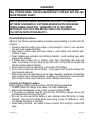
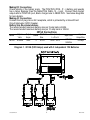
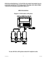
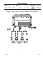
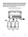
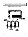
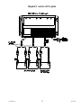
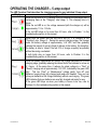
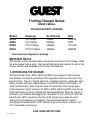
R
Trolling Charger Series
OWNER’S MANUAL
ON BOARD BATTERY CHARGERS
Models
2613A
2620A
2623A
2631A
Amperage
5,5,5 Amps
10,10 Amps
10,5,10 Amps
10,10,10 Amps
No. Of Banks
3 Bank
2 Banks
3 Banks
3 Banks
Volts
12/24/36
12/24
*12 or 24
12/24/36
* : See Connection diagrams for warnings.
IMPORTANT NOTICE
This manual contains important safety and operating instructions for the charger. Read
the entire manual before using. Also read all instructions and cautions for and on the
charger, batteries and equipment in the vicinity of the batteries.
1. INTRODUCING THE CHARGER
The Guest model 2613A, 2620A, 2623A and 2631A are designed to both recharge
your batteries, and extend your battery’s life in applications where it is stored for long
periods of time. They are “3-stage” electronic, completely automatic, lightweight, silent,
battery chargers and each output produces 12 Volts DC at either a full 5 Amps or 10
Amps (model specific), while using much less AC current than other charger types.
Unlike automotive “trickle” chargers, the 2613A, 2620A, 2623A and 2631A will not boil
off the electrolytes in properly installed and maintained batteries. When the charger is
attached to your batteries and plugged into a standard 115 Volt / 60 Hz AC outlet, the
red and green LED’s, mounted on the face of the charger let you know the unit is
recharging and maintaining your batteries. This sophisticated device is ideal for
recharging and maintaining the 12VDC batteries in your boat, electric vehicle or cart,
ATV, snowmobile or motorcycle.
SAVE THESE INSTRUCTIONS
727759 Rev H
WARNINGS
THIS CHARGER SHOULD BE USED TO CHARGE ONLY LEAD ACID OR GEL
CELL TYPE BATTERIES. USE ON OTHER BATTERY TYPES MAY EXPLODE AND
CAUSE PERSONAL INJURY.
RISK OF EXPLOSIVE GASES! WORKING IN THE VICINITY OF LEAD ACID
BATTERIES IS DANGEROUS. BATTERIES GENERATE EXPLOSIVE GASES
DURING NORMAL OPERATION. THEREFORE IT IS OF THE UTMOST
IMPORTANCE THAT EACH TIME BEFORE USING YOUR CHARGER YOU
FOLLOW THE INSTRUCTIONS EXACTLY.
Personal Safety Precautions
Adhere to the following personal safety precautions when installing or working with the
chargers:
1. Someone should be within voice range or close enough to come to your aid when
you work near a lead-acid battery.
2. Have plenty of fresh water and soap nearby in case battery acid contacts skin,
clothing, or eyes.
3. Wear complete eye protection and clothing protection. Avoid touching eyes while
working near a battery.
4. If battery acid contacts skin or clothing, wash them immediately with soap and
water. If acid enters the eye, flood the eye with cold, running water for at least ten
minutes and get medical attention.
5. Never smoke or allow an open flame in the vicinity of the battery.
6. Do not drop a metal tool onto the battery. It may spark, short circuit the battery and
may cause an explosion.
7. Remove all personal metal items such as rings, bracelets, necklaces, and watches
when working near a lead-acid battery. A battery can produce short circuit currents
high enough to weld a ring or the like to metal, causing a severe burn.
Preparing to Charge Precautions
Before charging a battery with the charger, read the following precautions:
1. Do NOT operate the charger if the cables or an LED is damaged.
2. Make sure all accessories on the product you are charging are OFF.
3. If the battery or batteries must be removed from the product, always remove the
grounded terminal from the battery first.
4. Be sure the area around the battery is well ventilated while the battery is being
charged. Gas can be forcefully blown away using a piece of cardboard or other
non-metallic material as a “hand fan”.
5. Clean battery terminals. Be careful to keep corrosion from coming in contact with
eyes.
727759 Rev I
2
EC 3429
6. Add distilled water in each cell until battery acid reaches levels specified by the
battery manufacturer, if applicable. Do not overfill. For a battery without cell caps,
carefully follow the manufacturer’s recharging instructions.
7. Never allow the ring terminals to touch each other.
8. NEVER charge a frozen battery.
9. Please be sure the DC system to which the charger is connected is not drawing
excessive current from the battery for extended periods of time while the charger is
operating. This is important to ensure the charger correctly transitions through each
charging stage to finish with the float voltage level. If the DC system is drawing
continuous current while charging, reduced life or damage to the battery may occur.
AC Connection and Grounding Precautions
DANGER
DO NOT OPERATE THIS CHARGER WITH A TWO BLADED ADAPTER PLUG OR
EXTENSION CORD. DOING SO CAN RESULT IN SERIOUS PERSONAL INJURY.
AFTER SECURING THE BATTERY CONNECTIONS, PLUG THE AC LINE CORD
INTO AN AVAILABLE AC OUTLET THAT IS PROTECTED BY A GROUND FAULT
CIRCUIT INTERRUPTER (GFCI) BREAKER.
CAUTION: To reduce the risk of shock, connect only to a properly grounded outlet.
NOTE: AC Line Cord color coding is EU style. Line = Brown, Neutral = Blue, Ground =
Green
2. INSTALLING THE CHARGER
Choosing Charging Location
The charger should have at least eight inches of unobstructed area on all sides of the
unit for effective cooling. The case of this charger will become warm during operation.
Because the charger is convection cooled (airflow over the back of the charger), the
optimum mounting position for the charger is vertical. Mounting on its back on a
horizontal surface may cause the charger to slightly reduce amperage output due to the
thermal protection built in. Do not install the charger on carpeted, upholstered, or
varnished surfaces.
Mounting the Charger
1. Use corrosion resistant ¼” dia. bolts, backed by a flat washer, and secured to the
mounting surface with a split-ring lock washer.
2. Hold the charger to the mounting surface and mark the holes.
3. Remove the charger and drill the mounting holes.
4. Align the charger and assemble the mounting hardware. Secure.
727759 Rev I
3
EC 3429
Making DC Connections
Check polarity of the battery posts. The POSITIVE (POS., P, +) battery post usually
has a larger diameter than the NEGATIVE (NEG., N, -) post. Connect Red charger
output wire to POSITIVE post, Black charger wire to NEGATIVE. See below diagrams
for more details.
Making AC Connections
Connect the AC plug into an AC receptacle, which is protected by a Ground Fault
Circuit Interrupter (GFCI) breaker.
Battery Size Recommendations
The recommended maximum battery size per 5 amp bank is 60AH.
The recommended maximum battery size per 10 amp bank is 120AH.
2613A Connections
Model
Output
Volts
Output
Amps
Banks
2613A
12/24/36
5/5/5
3
DC Cable
Size
Size (inches)
LxWxH
Input Volts
Input
Amps Max
6’/4’/4’
9.6 x 7 x 2.6
115VAC
50/60Hz
3.5 Amp
Diagram 1. 2613A (5/5/5 Amps) used with 3 independent 12V Batteries
727759 Rev I
4
EC 3429
2613A Connection Warnings: For the 2613A, only output 2 and output 3 may be
connected in parallel for a 12 V 10 amp output. The engine start output (Output
1) may not be connected in parallel with output 2 & 3.
2613A Connections
Diagram 2. 2613A used in a 24V system
To use a 2613A in a 36V system connect all 3 outputs in series.
727759 Rev I
5
EC 3429
2620A Connections
Model
Output
Volts
Output
Amps
Banks
2620A
12/24
10/10
2
DC Cable
Size
Size (inches)
LxWxH
Input Volts
Input
Amps Max
6’/6’
9.6 x 7 x 2.6
115VAC
50/60Hz
5 Amps
Diagram 3. 2620A (10/10 Amps) used with 2 independent 12V Batteries
727759 Rev I
6
EC 3429
NOTE: The 2620A can be used on 2 12 volt batteries or a 24V system. Outputs
may also be paralleled for a single 12V 20 amp output.
Diagram 4. 2620A (10/10 Amps) used with 2 independent 12V Batteries
727759 Rev I
7
EC 3429
2623A Connections
Model
Output
Volts
Output
Amps
Banks
2623A
*12/24
10/5/10
3
DC Cable
Size
Size (inches)
LxWxH
Input Volts
Input
Amps Max
6’/6’/6’
13 x 7 x 2.6
115VAC
50/60Hz
6.25 Amps
*Diagram 5. 2623A (10/5/10 Amps) used with 3 independent 12V Batteries
Engine Start
Battery
727759 Rev I
8
EC 3429
*2623A Connection Warnings: For the 2623A, only output 1 and output 3 may be
connected in parallel for a 12 V 20 amp output. The engine start output (Output
2) may NOT be connected in parallel with output 1 & 3. Output 1 and 3 may be
connected in series for a 24 V system, the engine start output (Output 2) may
NOT be connected in series with output 1 and 3.
*Diagram 6: 2623A used in a 24 V system
12V 5AMP, And A 24V 10AMP SYSTEM
positive
positive
+
-
Output #2
positive
+
-
+
Output #1
-
Output #3
Engine Start
Battery
727759 Rev I
9
EC 3429
2631A Connections
Output
Volts
Model
2631A
Output
Amps
12/24/36 10/10/10
Banks
3
DC Cable
Size
Size (inches)
LxWxH
Input Volts
Input
Amps Max
6’/6’/6’
13 x 7 x 2.6
115VAC
50/60Hz
7.5 Amps
Diagram 7: 2631A (10/10/10 Amps) used with 3 independent 12V Batteries
727759 Rev I
10
EC 3429
NOTE: The 2631A can be used on 3 12-volt batteries, a 24V system, or a 36-volt
system. Connections to the individual batteries are the same as shown
above. For a 2-battery system use only 2 banks, leave 3rd disconnected.
Diagram 8: used in a 24 V and 12 V system
727759 Rev I
11
EC 3429
Diagram 9: used in a 36 V system
727759 Rev I
12
EC 3429
3. OPERATING THE CHARGER – 10 amp output
The LED Function Chart describes the charging process for any individual 10 Amp output.
Display
Operating condition
When the red LED is on, it indicates that your batteries are discharged and is
recharging them at the "Charging" rate (stage 1). This charging rate is 10
Amps.
While the red LED is on, the voltage measured (with the charger on) will be
approximately 11.5 to 13 Volts.
If the red LED stays on for more than 24 hours, refer to Problem 1 in the
troubleshooting section in this manual.
When both the green and the red LED’s are on, it is charging at the
"Finishing" rate. (stage 2). During this second charging stage, the charger
holds the battery voltage at approximately 14.4 VDC, and then gradually
reduces the amount of current (Amps) it delivers to the battery. By doing this,
the battery is able to “absorb” the last 10% of charge as quickly as possible
without becoming overheated.
If both lights stay on longer than 24 hours, refer to Problem 2 in the
troubleshooting section in this manual.
When the battery approaches full charge, the charger switches into its third
charging stage, gradually reducing the current fed to the batteries to as low as
0.1 Amps. At the same time, it reduces its output voltage to a “Float” or
“Ready” charging rate of approximately 13.3 VDC, indicated by the green LED
light. This low “Float” or “Maintenance” voltage gently “tops off” your
batteries, keeping them fully charged and ready until needed. Now you can
store your batteries at full charge indefinitely without overcharging. The green
LED indicates that your batteries are now fully charged and ready for use.
If the green LED stays on when your battery is known to be low, refer to
Problem 3 in the troubleshooting section in this manual.
727759 Rev I
13
EC 3429
OPERATING THE CHARGER – 5 amp output
The LED Function Chart describes the charging process for any individual 5 Amp output.
Display
Operating condition
When the red LED is on, it indicates that your batteries are discharged and is
recharging them at the "Charging" rate (stage 1). This charging rate is 5
Amps.
While the red LED is on, the voltage measured (with the charger on) will be
approximately 11.5 to 13 Volts.
If the red LED stays on for more than 24 hours, refer to Problem 1 in the
troubleshooting section in this manual.
When both the green and the red LED’s are on, it is charging at the
"Finishing" rate. (stage 2). During this second charging stage, the charger
holds the battery voltage at approximately 14.8 VDC, and then gradually
reduces the amount of current (Amps) it delivers to the battery. By doing this,
the battery is able to “absorb” the last 10% of charge as quickly as possible
without becoming overheated.
If both lights stay on longer than 24 hours, refer to Problem 2 in the
troubleshooting section in this manual.
When the battery approaches full charge, the charger switches into its third
charging stage, gradually reducing the current fed to the batteries to as low as
0.1 Amps. At the same time, it reduces its output voltage to a “Float” or
“Ready” charging rate of approximately 13.3 VDC, indicated by the green LED
light. This low “Float” or “Maintenance” voltage gently “tops off” your
batteries, keeping them fully charged and ready until needed. Now you can
store your batteries at full charge indefinitely without overcharging. The green
LED indicates that your batteries are now fully charged and ready for use.
If the green LED stays on when your battery is known to be low, refer to
Problem 3 in the troubleshooting section in this manual.
727759 Rev I
14
EC 3429
4. TROUBLESHOOTING
Problem
1. Red LED stays
on for more than
24 Hrs.
Cause
1. One or more defective or
damaged cells.
Solution
1. Load test the batteries and
replace if necessary.
2. Remove the source of the
2. Charger has reduced its output
overload or short. Disconnect
the charger’s black
voltage below the normal level
due to a DC overload or a DC
(NEGATIVE) ring terminal from
the battery. Reapply AC power
short.
and the green LED only should
3. On-board DC systems are
now light.
drawing more current than the 3. Turn off all DC equipment while
charging.
charger can replace.
2. The red and
1. On-board DC systems are
1. Turn off all DC equipment while
green LED’s stay
drawing between 1.5 – 3.5A.
charging.
on for more than
2. Load test the batteries and
replace if necessary.
24 Hrs.
2. One or more defective or
damaged cells.
3. Apply a higher AC voltage
3. Extremely low AC voltage at
source or reduce the length of
the battery charger.
the extension cord.
4. Check battery manufacturer’s
specs on battery charging.
3. Green LED stays 1. Open DC output fuse.
1. Replace DC output fuse with a
on when the
Bussman (AGC-14) 15 amp
battery is known 2. Faulty or contaminated
2. Clean and tighten or repair all
to be low.
terminal connections.
terminal connections.
3. One or more defective or
3. Load test the batteries and
damaged cells.
replace if necessary.
3. Neither of the
1. No AC power available at the
LED’s turn on
charger
when the AC
2. Component failure
power is applied.
1. Connect AC power or reset the
AC breaker on the main panel
2. Return charger to the Guest
Service Dept.
5. MAINTAINING THE CHARGER
Periodically clean both battery terminals with baking soda and tighten all connections.
No other maintenance on the charger is required.
727759 Rev I
15
EC 3429
6. SPECIFICATIONS
Model
Output
Volts
Output
Amps
Banks
2613A
12/24/36
5/5/5
2620A
12/24
2623A
*12/24
2631A
DC Cable
Size
Size (inches)
LxWxH
3
6’/4’/4’
9.6 x 7 x 2.6
10/10
2
6’/6’
9.6 x 7 x 2.6
10/5/10
3
6’/6’/6’
13 x 7 x 2.6
12/24/36 10/10/10
3
6’/6’/6’
13 x 7 x 2.6
Input Volts
115VAC
50/60Hz
115VAC
50/60Hz
115VAC
50/60Hz
115VAC
50/60Hz
Input
Amps Max
3.5 Amp
5 Amps
6.25 Amps
7.5 Amps
FCC Class A EMC Notice
This equipment has been tested and found to comply with the limits for a Class A digital device,
pursuant to part 15 of the FCC Rules. These limits are designed to provide reasonable protection
against harmful interference when the equipment is operated in a commercial environment. This
equipment generates, uses and can radiate radio frequency energy and, if not installed and used in
accordance with the instructions, may cause harmful interference to radio communications.
Operation of this equipment in a residential area is likely to case harmful interference in which case
the user will be required to correct the interference at his own expense.
If this equipment does cause harmful interference to radio or television reception, which can be
determined by turning this equipment off and on, the user is encouraged to try to correct the
interference by one or more of the following measures:
---Reorient or relocate the receiving antenna.
---Increase the separation between the equipment and receiver.
---Connect the equipment into an outlet on a circuit different from that to which the
receiver is connected.
LIMITED WARRANTY
For two (2) years from the date of purchase, The Guest Co. will, at its discretion, repair or
replace for the original consumer, free of charge, any parts found defective in material or
workmanship.
This product is guaranteed for life against water damage.
Proof of purchase is required: A computerized register receipt is required. Hand-written receipts
are not accepted for warranty proof of purchase.
There is no other expressed warranty. Implied warranties, including those of merchantability
and fitness for a particular purpose, are limited to one year from the date of purchase. This is
the exclusive remedy and consequential damages are excluded where permitted by law.
Tel: (707) 226-9600
Fax: (707) 226-9670
727759 Rev I
Email: [email protected]
Website: www.marinco.com
16
EC 3429