1
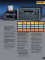
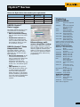
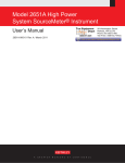
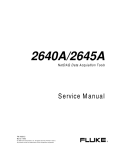
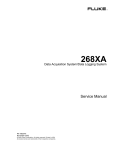
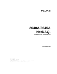
Data Acquisition
where you need it
when you need it
how you need it
•
•
•
•
•
•
Accurate
Flexible
Easy-to-use
Portable
Networked
Expandable
to thousands
of channels
Fluke Data Acquisition Solutions
Adapt to Your Needs
Get the data you
want, where,
how and when
you want it.
Fluke gives you a broad choice in
how you collect and transfer data
for process monitoring and laboratory test systems. You can choose
a stationary or portable system.
Transfer data to internal memory,
to a removable memory card, or to
your PC. Choose a standalone or
distributed networked units. And
you can expand your system from
20 to 1,000+ channels, depending
on the series.
Regardless of which you choose
you’ll always get Fluke’s well
known accuracy, reliability, speed,
and ease of use. All Fluke data
acquisition products feature unique,
built-in universal signal conditioning and a plug-in Universal
Input Module to enable you to
measure virtually any type of
signal without having to purchase
extra equipment. Plus, powerful,
easy-to-use Windows-based software supports easy configuration,
advanced trend analysis, professional-quality reporting, and
enables you to quickly build
human-machine-interfaces
without any programming.
Any data acquisition application
that requires high accuracy, easy
setup, and convenience calls for
Fluke data acquisition products,
which is why you’ll find them
widely used for:
• R & D applications
• Environmental testing
• Product testing and process
validation
• Troubleshooting
• Manufacturing test systems
Whether you’re gathering data at
a high-voltage substation, a
nuclear power plant, in a clean
room, on a production line, or on
an automotive test track, Fluke
data acquisition products can
make your job easier by delivering
the data you need, when and
where you need it.
1
Accuracy, flexibility
and ease of use come
standard
From a 20-channel Hydra™
Series portable data logger to
a 1,000+ channel precision
temperature measurement 2680
data acquisition system, Fluke
data acquisition products share
several unique advantages.
• Built-in signal conditioning
saves time and money
Fluke’s data acquisition products were the first to integrate
signal conditioning directly
into the instrument. Assign
any measurement function—
thermocouple, RTD, volts,
frequency, or ohms—to any
or all channels.
• Removable Universal Input
Module connects any signal
Our unique, patented
Universal Input Module allows
you to connect and measure
virtually any electrical or
physical parameter. Thermocouple reference junction
compensation occurs automatically by sensing the temperature of the input module’s
isothermal block. Virtually any
combination of sensor or
signal lines may be connected
to the input module, which is
plugged into the back of the
data acquisition unit. You can
pre-wire extra input modules
at each test site and move
your data acquisition units
from one location to another.
• Rugged design for reliable
performance. Fluke data
acquisition products are
designed to stand up to rugged
industrial environments with
some models operating from
-20° to 60° C. A sturdy metal
chassis effectively shields
against electromagnetic interference so you can maintain
high measurement accuracy
on low-level signals regardless of surrounding noise.
They are tested to stringent
•
•
•
•
•
•
•
shock and vibration standards
and to withstand surges of up
to 1500V input on most models.
All units conform to IEC, CSA,
and CE standards.
Isolated circuitry for top
accuracy. Fluke analog measurement circuitry is fully
isolated channel to channel,
input to output, and input to
ground, supporting direct
measurement of voltages up to
300 V ac rms.
Scan triggers, including
interval, push button, external,
and alarm triggers, scan all
defined channels.
Mx+B scaling is available on
each channel
Channel monitoring from the
front panel. Select measurement
rates from 4 readings per second
(rps) up to 1,000 rps, depending
on model. Front panel lockout
prevents unauthorized tampering
or accidental setup changes.
Two alarms can be set for
each channel
Real-time clock offers precise
time stamping of data
Closed-case calibration
delivers reliability and
traceability
The Fluke 2680 Series:
Precise and versatile
standalone or networked
data acquisition
The Fluke 2680 Series delivers the
precision necessary for meticulous
lab work along with the rugged
flexibility to meet the ever
changing needs of industrial applications. Run one standalone data
logging system with 20 to 120
universal channels or connect
several networked data acquisition
systems to serve 2,000+ channels
on your LAN.
The Fluke Hydra™ Series:
Portable, flexible data
acquisition anywhere you
need it.
The portable 20-channel Fluke
Hydra Series transfers data either
to internal memory (Hydra Data
Logger), to a removable memory
card (Hydra Data Bucket), or
directly to your PC (Hydra Data
Acquisition Unit).
Model Series
Universal
Signal
Conditioning
Basic DC
Accuracy
PC Interface
Channels
Per System
Max
Throughput
Rate (Rdgs/s)
Hydra Series
Yes
0.018 %
RS-232
PCMCIA
IEEE-488
21 to 42
17
NetDAQ
Yes
0.01 %
Ethernet
10 BaseT
20 to 400
1000
2680 Series
Yes
0.01 %
Ethernet
10/100 BaseT
20 to 2000+ 3000
The Fluke NetDAQ® Series:
Distributed, networked
data acquisition that
works with what you have
Distributed Fluke NetDAQ units
plug right into your existing
networks to send data directly
to a PC. This saves the cost of
setting up a new network
and allows multiple users to
simultaneously view data in real
time. NetDAQ units can also be
used as a portable dedicated
system connected to a notebook
computer for maintenance,
product validation, research, and
troubleshooting applications.
Versatile software
for easy setup
Windows®-based software makes
our data acquisition instrument
configuration and data analysis
as easy as a few mouse clicks.
• Powerful, flexible, and easyto-use Fluke DAQ software,
included with every 2680
Series unit, makes it easy to
instantly configure your 2680A
Data Acquisition System or your
•
•
2686A Data Logging System.
You can add OLE for Process
Control (OPC) and/or powerful
Human-Machine-Interface (HMI)
development system modules at
any time to expand your application’s capability.
Data logger software for the
Hydra Series and for NetDAQ
enables you to create multiple
setup files and save them to a
hard disk or to a memory card
for quick reconfiguration. It also
enables you to save data in a
variety of file formats and
establish Dynamic Data
Exchange (DDE) link with
spreadsheet programs to
analyze the data in real time.
Optional Trend Link for Fluke
software provides comprehensive trend plotting, batching,
and analysis capabilities for the
Hydra and NetDAQ systems. It
combines the look and feel of a
chart recorder with the analytical power of a PC.
2
Top precision and
scalability for
standalone or
networked data
acquisition
The Fluke 2680 Series data
acquisition systems combine
the best of lab precision with
the rugged flexibility required
in rapidly changing industrial
applications. Whether you
choose the 2680A Data Acquisition System with high-speed
10/100BaseT Ethernet network
support or the 2686A Data
Logging System, you can seamlessly expand your system any
time, from 20 to more than
2,000 channels, just by adding
modules and chassis.
Both models feature six slots
in each chassis that you can fill
with modules as needed to
meet your application requirements. Five slots in each chassis
are available for any combination of 2680 Series 20-channel
analog input modules. The sixth
slot is reserved for a 2680
Series digital I/O relay module
to add control capabilities to
your system. If you don’t need
the sixth slot for control, you
can plug in an additional
analog input module, increasing
your channel count to 120 in a
single chassis.
You can also link multiple
120-channel systems together
seamlessly for the widest
possible view of your data. And
with TCP/IP connectivity you
2686A Data Logging System
can connect to existing LANs to
distribute information wherever it
needs to go. Whether you need
speed and throughput, isolated
precision, or digital I/O and relays,
the Fluke 2680 Series can scale up
to thousands of channels to meet
your needs.
•
The Fluke 2680
Series: Key features
•
•
•
•
120-channel capacity chassis
designed for small- and largescale precision data acquisition
applications.
User-scalability from 20 to
120 universal analog input
channels, which can include
digital input/output and alarm
contact outputs in a single
chassis.
De facto standard Ethernet
TCP/IP protocols which
provide a network interface to
10/100 BaseT.
•
•
•
•
3
Universal Input Modules
provide precision measurement
of thermocouples, dc voltage,
ac voltage, Ohms, RTDs, thermistors, current, frequency.
Connect any input type to any
channel to match your application requirements – no “wasted”
channels.
Superior thermocouple
measurement accuracy
(J, K, R, S, T, N, L, U, C, B)
Multiple speed and scan
selections
Universal input conditioning
for any input, on any channel,
any time (Vdc, Vac, Ohms,
frequency, RTD, thermocouple,
thermistor or current)
Optional precision, highisolation analog universal
input module (PAI) or fast
scanning analog universal
input module (FAI) to connect
and measure virtually any electrical or physical parameter
Computed channels, in addition to the 20 analog channels,
that perform custom calculations
using addition, subtraction,
multiplication, division, log,
natural log, exponent, square
root, absolute value, and integer
functions. Math channels
feature the same alarm capability as analog channels which
saves having to perform separate post calculations on
channel data. It is also especially useful for monitoring and
alarming on real-time calculated values such as power,
flow, volumes, pressure, and
more.
2680 Series
Fluke 2680 Series chassis and module selection chart
Chassis
On board
memory
PC interface
DIO/chassis
2680A
Analog
channels/
chassis
120*
none
2686A
120*
Module
20 DIO + 8 relay
DPST relays
20 DIO + 8 DPST
relays
Basic TC accuracy
(type K)
2680A-FAI
Readings/
sec (max)
1000
PCATA Flash
to 1 GB
Channels/type
Ethernet
10/100 BaseT
Ethernet 10/100
BaseT
Isolation
(volts DC)
50
2680A-PAI
100
2680A-DIO** N/A
•
•
•
•
20 / universal
analog
20 / universal
analog
20 / digital;
8 / relay
Fluke DAQ software which
controls all functions and data
files, communicates with and
controls Fluke 2640A, 2645A
NetDAQ® products, provides
real-time and historical trending
Powerful optional software
for reporting, HMI development,
and OPC server.
20 digital I/O and 8 form C,
1 Amp relay output module
for hard control of equipment
Multiple power sources: 100
to 240 V and 9 V to 45 V dc
Choose your chassis
for standalone or
networked data
acquisition
150 / 300
30
N/A
2686A Data Logging System
chassis
The Fluke 2686A Data Logging
System writes data to a memory
card for easy retrieval and storage,
making it ideal for remote locations and mobile or non-computer
assisted data logging applications.
The system comes with a 16 MB
PCATA flash memory card, and
supports memory cards of up to 1
GB to log data in standalone mode
for easy storage and retrieval. The
2686A is easily configured for
stand-alone data logging operations by simply selecting a preset
configuration from the memory
card. It can also be used in
networks in tandem with the
2680A to provide the extra data
security of a memory card.
Choose your
modules
You can equip each 2680 Series
chassis with up to six modules of
the same type or combine fastanalog input (2680A-FAI) and
precision analog input modules
(2680A-PAI) along with a digital
I/O (2680A-DIO) and relay module.
Both the 2680A-FAI and the
268A0-PAI modules support a wide
range of inputs including dc volts,
ac volts, RTD, Ohms, thermocouple,
thermistor, dc current, ac current,
and frequency. Other sensors and
transducers, such as load cells,
pressure sensors, and displacement
sensors can be easily incorporated
into your measurement system.
Buy just the modules you need in
the combinations you need them
and expand your system as your
requirements grow.
2680A-FAI: The speed to
capture dynamic process
changes
The Fluke 2680A-FAI module is a
perfect choice when you need a
lot of information in a hurry and
still need to maintain a high
degree of accuracy for your measurements. The 2680A-FAI module
provides chassis throughput rates
of more than 3,000 channels-persecond. Specially manufactured
The Fluke 2680 Series offers the
choice of networked data acquisition, stand-alone data logging, or a
combination of both. Choose from
two basic chassis models—the
2680A Data Acquisition System or
the 2686A Data Logging System
and then add the modules as
needed to meet your requirements.
2680A Data Acquisition
System chassis
The Fluke 2680A Data Acquisition
System is the choice for multichannel applications requiring
reliable Ethernet communications.
It features a front-end style data
acquisition system that communicates and distributes data
anywhere you need it to go. The
10 BaseT and 100 BaseT communications interface makes it
compatible with both older and
newer network platforms.
2680 Series DIO Module
and Universal Input Module
4
field effect transistors (FETs) allow
up to + 50V input, well above the
15V industry norm, and channelto-channel isolation to give you
more confidence in the integrity of
your measurements.
2680A-PAI provides high
precision and high isolation
for the most demanding jobs
The Fluke 2680A-PAI 20-channel
high precision, high isolation
module serves the most
demanding jobs where precision
and isolation are critical. Some of
the most notable applications for
this module include temperature
measurement in semiconductor
and pharmaceutical manufacturing, as well as nuclear plant
performance monitoring. The
2680A-PAI module offers 300V of
isolation on two channels and
150V on 18 channels, as well as
18-bit resolution and excellent
thermocouple accuracy, all in a
scalable system.
2680A-DIO: Digital I/O and
relay outputs add control
For data acquisition systems that
also require control functionality,
the Fluke 2680A-DIO digital I/O
and relay output module provides
20 digital I/O and eight hardcontact 1 Amp relays to provide
the security and control you need.
This equips each chassis to
respond to a wide range of alarm
or control situations. The 2680ADIO also includes an up/down
counter with preset start count
capability, so you don’t need to
begin all counts at zero.
Model 2680A-PAI Module
Input
Range
Resolution
Accuracy (3-Sigma)1
DC Volts
90 mV to 150/300 V
0.3 mV to 1 mV
AC Volts2
300 mV to 150/300 V
10 mV to 10 mV
Resistance
300 Ω to 3 MΩ
1 mΩ to 10 Ω
Frequency
15 Hz to 1 MHz
0.01 Hz to 100 Hz
RTD (Pt100)
-200 to 600 °C
0.003 °C
Thermocouples
J
-100 to 760 °C
0.02 °C
K
-100 to 1372 °C
0.02 °C
T
-100 to 400 °C
0.02 °C
Other Thermocouple types R, S, B, C, E, N, L, U
0.01 %
0.3 %
0.015 %
0.05 %
0.06 °C
0.35 °C
0.4 °C
0.3 °C
Model 2680A-FAI Module
Input
Range
Resolution
Accuracy (3-Sigma)1
DC Volts
90 mV to 50 V
3 mV to 10 mV
AC Volts2
300 mV to 30 V
10 mV to 1 mV
Resistance
300 Ω to 3 MΩ
10 mΩ to 100 Ω
Frequency
15 Hz to 1 MHz
0.01 Hz to 100 Hz
RTD (Pt100)
-200 to 600 °C
0.03 °C
Thermocouples
J
-100 to 760 °C
0.2 °C
K
-100 to 1372 °C
0.2 °C
T
-100 to 400 °C
0.2 °C
Other Thermocouple types R, S, B, C, E, N, L, U
0.02 %
0.3 %
0.02 %
0.05 %
0.16 °C
0.7 °C
0.8 °C
0.7 °C
1
Total instrument accuracy for 90 days following calibration and ambient temperature range of 18 to
28 °C. Includes A/D errors, linearization conformity, initial calibration error, isothermality errors, reference junction conformity and power line voltage effects within the range from 107 V ac to 264 V ac.
2
Accuracies for crest factor to 2.0.
2686A Active Channels and Memory Card Capacity (Scans)
Memory Card / 20 ch
Active Channels
40 ch
60 ch
80 ch
100 ch
120 ch
16 MB
128 MB
256 MB
512 MB
1 GB
66,765
528,000
1.056M
2.112 M
4.224 M
50,074
400,000
800,000
1.6 M
3.2 M
40,059
320,000
640,000
1.28 M
2.56 M
33,382
264,000
528,000
1.056 M
2.112 M
28,613
224,000
448,000
896,000
1.792 M
100,548
800,000
1.6 M
3.2 M
6.2 M
Estimating space: 80 bytes / scan + 4 bytes / channel scanned. (Allow 4.5 % overhead for card
formatting)
5
2680 Series
Fluke 2680A-DEVSW:
HMI development software
The optional 2680A-DEVSW
Indusoft Web Studio development
software is an object-oriented
development program that works
with Fluke DAQ software. This
unique development software
enables programmers and nonprogrammers to develop modern
HMI’s which open graphical
windows to your application.
Fluke 2680A-OPC:
Communicate with any
application supporting
OLE for Process Control
This OPC server software provides
the configuration interface for the
2680 Series and also offers a
common communication link to
any software package that
supports OPC. Create custom
applications using 2680AOPC software and just about
any popular industrial software package such as
Wonderware®, LabVIEW™,
Test Point, or Indusoft Web
Studio, as well as software
from Canary Labs, Daisy
Labs,
and others. Open, nonproprietary OPC support
enables you to use the software you choose or the software you create.
2680 Series Fluke DAQ Software
Powerful Fluke
DAQ software
streamlines setup
and performance
Each Fluke 2680A and 2686A
comes with our powerful, highly
flexible, and easy-to-use Fluke
DAQ configuration software.
Fluke DAQ software enables you
to instantly configure your 2680
Series unit for any situation,
configuring each input for:
• Input type
• Alarms
• Math functions
• Totalizer function
• Digital I/O lines
• Scan speed
• Interval
• Trigger type
You can also use Fluke DAQ software to set up data files, collect
and chart data in real-time or
historical mode, and manage PC
card files. And you can use Fluke
DAQ to collect data from your
system the way you need to and
distribute it where you want it.
You can share data with others,
anywhere on your LAN or
anywhere around the world using
Web servers.
Fluke DAQ software also
enables you to integrate Fluke
NetDAQ® data acquisition products
(2640A and 2645A) into your
2680 Series system, providing
almost unlimited channels working
together seamlessly.
Optional software
extends system
capabilities
Fluke 2680A-DLL library:
For developing or modifying
applications
The 2680A DLL library provides
the full DLL toolbox for application
software developers who need to
write original programs for the
2680 Series, using Visual C++,
Visual Basic, and other languages.
Fluke has partnered with industrial software developer Indusoft to
create additional tools to extend
the power of your 2680 Series
system. These optional software
tools enable you to create HMI’s
and develop custom applications
that interact with other equipment
and software packages. Refer to
the Optional Software section at
the back of this brochure for more
information.
6
•
•
•
•
•
•
Universal Input Module:
Connect 20 analog inputs or
virtually any sensor type
without external signal
conditioning
2680A Series Interfacing:
Compatible with 100BaseT
and 10BaseT standards; uses
TCP/IP protocol via RJ45
connector, Cat 5. RS-232
input for calibration.
External Trigger: Activate
scanning with real-world
events
Totalizer: Pre-settable
starting count up/down
counter
Alarm Outputs: Flag out-oflimit conditions to external
devices
Power: Accepts 100 to
240 V ac, or 9 to 45 V dc.
Can operate from both
simultaneously for fail-safe
power operation.
2680 Series Chassis
Channel capacity
(2680A or 2686A)
20 to 120 channels per chassis
(6 analog input modules of 20
channels each)
One master alarm (open collector)
per chassis
Communications:
10BaseT/100BaseT, TCP/IP via
RJ45 connector, Cat 5
Math functions
In addition to its analog and
digital input channels, each
system supports 60 computed
channels. Calculations include
time & rate, addition, subtraction,
multiplication, division, log,
natural log, exponent, square root,
absolute value, integer function
and average.
Measurement speed
(2680A-PAI)
Slow: 6 readings/second
nominal
Medium: 41 (50 Hz), 48 (60 Hz)
readings/second nominal
Fast: 143 readings/second
nominal (5 readings/second for
VAC nominal, 140 readings/
second on 300 Ω range,
37 readings/second on 3 MΩ
range)
Measurement speed
(2680A-FAI)
Slow: 45 (50 Hz), 54 (60 Hz)
readings/second nominal
Medium: 200 readings/second
nominal
Fast: 1000 readings/second
nominal (5 readings/second for
VAC nominal, 370readings/
second on 300 Ω range,
44 readings/second on 3 MΩ
range)
7
Analog to digital converter
2680A-PAI: 18 bit, multi-slope
type
2680A-FAI: 16 bit, multi-slope
type
Common mode rejection
2680A-PAI:
AC: ≥120 dB (50/60 Hz, ±0.1 %
max 1 kΩ source imbalance)
DC: ≥120 dB
2680A-FAI:
AC: ≥100 dB (50/60 Hz, ±0.1 %
max 1 kΩ source imbalance)
DC: ≥100 dB
Normal mode rejection
50 dB @ 50/60 Hz, ±0.1 %
Common mode voltage
maximum
2680A-PAI: 300 V DC or V AC rms
(channels 1,11); 150 V DC or V AC
rms (all other channels)
2680A-FAI: 50 V DC or 30 V AC
rms (all channels)
2680A-DIO
Totalizing input
Pre-settable starting count
up/down counter
DC coupled, non-isolated,
max +30 V, min -4 V
Max count: 4,294,967,295
Minimum signal: 2 V peak
Threshold: 1.4 V
Rate: 0-5 kHz (debounce off)
Hysteresis: 500 mV
Input debouncing: None or 1.66 ms
2680 Series Specifications
Digital inputs/outputs: 20
Threshold: 1.4 V
Hysteresis: 500 mV
Maximum input: +30 V,
min -4 V; non-isolated
Logical “zero” output:
0.8 V max |out = -1.0 mA
(1 LSTTL load equivalent)
1.8V max |out = -20 mA
3.25V max |out = -50 mA
Logical “one” output:
Output voltage depends on
external load
3.8V min|out = 0.05 mA
(1 LSTTL load equivalent)
Relays
Quantity: 8
Type: Form C; DPST
Current: 1 amp, non-inductive
Operation time: 75 ms
Alarm associations
Each Digital I/O may be randomly
assigned as a digital input, status
output, or alarm output (associated
with any input channel or channels)
Trigger input
Minimum pulse: 5 µs
Minimum latency: 100 ms
Input “High”: 2.0 V min,
7.0 V max
Input “Low”: -0.6 V min, 0.8 V
max non-isolated, contact
closure and TTL compatible
Clock
Accurate to within 1 minute/
month for 0 °C to 50 °C range
General
Specifications
Power
100 to 240 VAC, 50 or 60 Hz
100 VA max, or 9 to 45 VDC
(50 W max - all slots filled
+ memory card installed) (if both
sources are applied simultaneously, the greater of AC or DC is
used.), at 120 V AC the equivalent
DC voltage ~14.5 V
Temperature, humidity
(non-condensing)
Operating:
-20 °C to 28 °C, ≤90 % RH;
28 °C to 40 °C, ≤75 % RH;
40 °C to 60 °C, ≤50 % RH
Storage:
-40 °C to 70 °C, 5 % to 95 % RH
Altitude
Operating: 2000 m
Storage: 12,200 m
Standards
All inputs: IEC Overvoltage
rating Category II
Product conforms to the following
safety and emission standards:
EN50082-2
EN55022-1
EN55011 class A
EN610000-4-2,3,4,6,8
EN61326
EN61010-1, CAT II
CSA C22.2 No. 1010.1
Operating temperature
-20 °C to 60 °C (-4 °F to +140 °F)
Storage temperature
-40 °C to 70 °C (-40 °F to +158 °F)
Ordering
information
Hardware:
Model #
2680A
2686A
2680A-FAI
2680A-PAI
Size
18.6˝ x 17˝ x 9.3˝
(473 mm x 423 mm x 237 mm)
Weight
2680A/2686A chassis only:
18.86 lbs. (8.47 kg)
2680A-FAI: 1.74 lbs. (0.79 kg)
2680A-PAI: 2.66 lbs. (1.21 kg)
2680A-DIO: 1.75 lbs. (0.80 kg)
Interfaces
Ethernet: Conforms to IEEE 802.3
Ethernet standard,
compatible with 100BaseT and
10BaseT standards, uses TCP/IP
protocol
RS-232C: For calibration only
System Requirements
• IBM compatible, Pentium II
processor
• Microsoft Windows®
NT/98/2000/XP
• 64 MB RAM
• 150 MB free hard disk space
• VGA or SVGA display, 100 %
IBM compatible with 2 MB
Video RAM (VRAM)
• CD-ROM drive
• Microsoft Internet Explorer 4.0
or later
2680A-DIO
Description
Data Acquisition System
Chassis, 6 slots
Data Logging System
Chassis, 6 slots, with
ATA Flash memory drive,
includes 16Mb memory
card
Fast Analog Input module
20 universal channels,
50V Max isolation. 1000
ch/sec scan rate, 16 bit
resolution
Precision Analog Input
module 20 Universal
channels, 300V Max
isolation, 18 bit resolution
140 ch/sec scan rate
Digital I/O and relay
module, 20 DIO , 8, 1 Amp
contacts, Totalizer (one per
chassis max)
Software:
Application Description
2680A-APSW Fluke DAQ configuration
software for 2680 Series
(included with 2680A
and 2686A)
2680A-904
Trend Link for 2680
Series; includes 2680AOPC server software
2680A
Indusoft Web Studio,
Development software
-DEVSW
for Fluke DAQ
DLL Library for
2680A-DLL
2680 Series
OPC software for
2680A-OPC
2680 series
Accessories:
Model #
2680A-180
2680A-102
2620A-101
2680A-800
2680A-801
2680A-802
2680A-805
2680A-810
Y2680
Description
Universal Input Module,
extra connector
2680A-DIO connector
module, extra connector
Shunt resistor set (12 ea),
10 ohm, 0.1 %
16 MB ATA Flash memory
card for 2686A
128 MB ATA Flash
memory card for 2686A
256 MB ATA Flash
memory card for 2686A
512 MB ATA Flash memory
card for 2686A
1 GB ATA Flash memory
card for 2686A
19-inch rack mount kit
for 2680 Series
8
Portable, flexible
solutions for standalone or PC-based
data acquisition
The Hydra Series offers easy
portability along with Fluke’s
built-in signal conditioning and
Universal Input Module at a
price to fit your budget. You can
easily retrieve data from Fluke
Hydra units via the RS-232
interface or through a modem
in upload or real-time mode.
Channel information and measurement parameters can be set
up directly from the front panel
or your PC.
Choose from three Fluke
Hydra Series models, all
featuring removable memory
card data storage, internal
memory storage, and direct
real-time data transfer options.
Should power fail, these instruments automatically resume
data collection when power is
restored.
Hydra Data Bucket
Key Hydra™ Series
features
2635A Hydra
Data Bucket
•
The versatile Hydra Data Bucket is
the ideal choice for gathering and
transporting large volumes of data
and for working extended periods
from remote locations. It offers:
• Flexible storage. The Hydra
Data Bucket comes with a
256K PCMCIA card and can be
equipped with optional 1 MB,
2 MB, or 4 MB memory cards to
suit your data storage needs.
• Versatile data transfer. Data
may be uploaded from these
cards via the Hydra RS-232
port, the optional 263XA-803
memory card drive, or from your
computer’s standard PCMCIA
slot. You can transfer real-time
data to a PC at the same time it
is recorded to the memory card.
• Quick setup. Simply push a
few front panel buttons or load
instrument setups from the
memory card.
• Fail-safe features. The Hydra
Data Bucket warns of a low
battery or low memory condition
on the memory card. Its internal
memory buffer continues to store
up to 70 scans while the card is
removed and replaced.
•
•
•
•
9
Review the min/max and last
readings from the front panel
Channel 0 accepts standard test
leads from the front panel for
quick measurements
Monitor a selected channel from
the front panel
Use the Channel function to
configure measurement type
and range for each individual
channel
Use the Memory Card Drive (in
2635A only) to store data and
instrument configuration on a
portable, non-volatile memory
card and transfer collected data
to your PC for later analysis
Hydra™ Series
Choose the Hydra Series that matches your requirements
Model
2635A Data Bucket
2625A Data Logger
2620A Data Acquisition Unit
2620A/05 Data Acquisition Unit
Universal Signal
Conditioning
Yes
Yes
Yes
Yes
Nonvolatile
Data Storage
PCMCIA Card
Internal
None
None
Interface
RS-232
RS-232
RS-232
IEEE-488
Ordering
information
2620A
2625A Hydra™
Data Logger
The Hydra 2625A provides a lowcost alternative for standalone
monitoring operations with:
• Built-in nonvolatile memory
that can store more than 2000
scans.
• Flexible data retrieval that
enables you to upload stored
data, or transfer real-time data
via modem or directly to your
PC via the RS-232 port.
2620A Hydra™ Data
Acquisition Unit
The Hydra 2620A is ideal for
applications that require direct
connection to a PC for real-time
data collection.
• Easy-to-use front-end. An RS232 serial interface makes it
easy to connect the Hydra Data
Acquisition Unit to a PC or
modem for real-time data
acquisition. The 2620A can also
be used as a 20-channel panel
meter.
• IEEE interface. An optional
IEEE-488 interface allows you
to easily integrate the 2620A
with other IEEE-488 instruments and your PC. The 2620A
delivers workhorse performance
for a wide variety of applications
such as test and monitoring
systems.
Menu-driven software simplifies setup
Hydra Logger software, included
with all Hydra models, provides an
intuitive graphical interface that
makes it even easier to configure
and access the powerful features
of your Hydra units without any
programming.
Hydra Data Acquisition
Unit
2620A/05
Hydra Data Acquisition
Unit with IEEE-488
interface
2625A
Hydra Data Logger
2635A
Hydra Data Bucket
(256 KB memory card)
2635A-1MB Hydra Data Bucket
(1 MB memory card)
2635A-2MB Hydra Data Bucket
(2 MB memory card)
2635A-4MB Hydra Data Bucket
(4 MB memory card)
Includes: Instrument, Universal Input
Module, line cord, user manual, Hydra
Logger Software, RS43 cable
Options and accessories
2620A-100
Extra Universal Input
Module
263XA-803
External PC Memory
Card Drive
263XA-804
Memory Card-256 KB
263XA-805
Memory Card-1 MB
263XA-806
Memory Card-2 MB
263XA-807
Memory Card-4 MB
RS43
RS-232 cable;
(DB9 to DB9), Hydra
to PC; 1.8m (6 ft)
26XXA-600
Hydra Portable Battery
Pack
Current Shunt, 10 Ω,
2620A-101
0.1 % for 0 to 100 mA,
Qty (12)
M00-200-634 19" Rack Mount Kit
Y8021
Shielded IEEE-488
Cable, 1 Meter
P/N 889589 Service Manual
Application software*
Hydra Logger
Hydra Logger with
Trending
Trend Link for Fluke
2600A-904
*IEEE –488 not supported
2635A-901
2635A-902
10
•
Universal Input Module:
Connect 20 analog inputs of
virtually any sensor type
without external signal
conditioning
•• Hydra Interfacing: Use
RS-232 interface to connect
to printer, PC or modem
• External Trigger: Activate
scanning with real-world
events
• Totalizer: Count on/off
events, updated at every
scan
Alarm
Outputs: Flag out-of•
limit conditions to external
devices
• Power: Accepts 90-264 V ac,
or 9-16 V dc. Can operate
from both simultaneously
Hydra Series (Universal Input Module Removed)
Hydra™ Series
Channel capacity
Analog inputs: 21
Digital I/0 and alarm outputs:
12 total
Totalizer: 1
Measurement rate
Slow: 4 Rdgs/s nominal
Fast: 17 Rdgs/s nominal
(1.5 Rdgs/s for V ac, Hz and Ω
inputs nominal)
Analog to digital converter
Dual slope type, linear to 17 bits
Common mode rejection
AC: ≥120 dB (50/60 Hz, ±0.1 %
max 1 kΩ source imbalance); dc:
≥120 dB
Totalizing input
DC coupled, non-isolated, max
+30V, min -4 V
Max count: 65,535
Minimum signal: 2 V peak
Threshold: 1.4 V
Rate: 0-5 kHz (debounce off)
Hysteresis: 500 mV
Input debouncing: None or 1.66 ms
Digital inputs
Threshold: 1.4 V
Hysteresis: 500 mV
Maximum Input: +30 V, min -4 V;
non-isolated
Normal mode rejection
53 dB (60 Hz, ±0.1 %)
47 dB (50 Hz, ±0.1 %)
Digital/alarm outputs
The open collector output lines are
non-isolated, TTL compatible
Common mode and normal
mode voltage maximum
300V dc or V ac rms (channels
0,1,11) 150V dc or V ac rms (all
other inputs)
Alarms associations
Alarm outputs 0-3 are fixed
assignments associated to channels 0-3. Alarms for channels 4-19
are mapped to digital I/O lines.
Digital I/O may be used as a
digital input or alarm status output
(associated with any input channel
or channels).
Isolation
Analog input to analog input, and
analog input to any digital input:
meets IEC 1010 for 300/150 volts
reinforced and ANSI/ISA-S82.011994 and CSA-C22.2 for 250 volts
single insulation
11
Current measurements
AC or dc current measurements up
to 100 mA may be accomplished
using the 2620A-101 10 Ω Current
Shunt Strip
Hydra™ Series Specifications
Hydra™ Series
Input
Range
DC Volts
90 mV to 150/300 V
AC Volts2
300 mV to 150/300 V
Resistance
300 Ω to 10 MΩ
Frequency
15 Hz to 1 MHz
RTD (Pt100)
-200 to 600 ºC
Thermocouples
J
-100 to 760 ºC
K
-100 to 1372 ºC
T
-150 to 400 ºC
Other Thermocouple types R, S, B, C, E, N
Resolution
Accuracy (3-Sigma)1
1 µV to 10 mV
10 µV to 10 mV
10 mΩ to 1 KΩ
0.01 Hz to 1 kHz
0.02 ºC
0.018 %
0.13 %
0.013 %
0.05 %
0.05 ºC
0.1 ºC
0.1 ºC
0.1 ºC
0.39 ºC
0.45 ºC
0.39 ºC
Detailed specifications are available on request.
1
Total instrument accuracy for 90 days following calibration and ambient temperature range of 18 to 28
°C. Includes A/D errors, linearization conformity, initial calibration error, isothermality errors, reference
junction conformity and power line voltage effects within the range from 90 V ac to 264 V ac.
2
Accuracies for crest factor to 2.0.
Hydra™ 2635A Memory Card capacity—number of scans
Memory Card Size
Channels in Scan
256 KB
1 MB
2 MB
4 MB
4
8900
36860
74110
149039
Trigger input
Minimum pulse: 5 µs
Maximum latency: 100 ms
Repeatability: 1 ms
Input “High”: 2.0 V min, 7.0 V max
Input “Low”: -0.6 V min, 0.8 V max
non-isolated, contact closure and
TTL compatible
Clock
Accurate to within 1
minute/month for
0 to 50 °C range
Power
90 to 264 V ac 50 or 60 Hz (<10
watts), or 9 to 16 V dc (<4 watts).
(If both sources are applied simultaneously, the greater of ac or dc
is used.) At 120 V ac the equivalent dc voltage ~14.5 V.
Temperature, humidity
(non-condensing)
Operating:
0 to 28 °C, ≤90 % RH
28 to 40 °C, ≤75 % RH
10
4800
19860
39910
80251
20
2710
11210
22550
45359
40 to 60 °C, ≤ 50 % RH
Storage: -40 to 75 °C,
5 to 95 % RH
Electromagnetic
Interference (EMI)
Passes FCC EMI Class B Equipment, VDE 0871B, and CEEN61010, CE approved
Safety
Complies with applicable sections
of the IEC1010, ANSI/ISA-S82.011994, CSA-C22.2, and CE standards as noted above
Hydra™ 2625A Data
Memory
•
Stores 2,047 scans
Scan contents
• Memory life: 5 years minimum;
at 25 °C
• Date and time stamp
• All defined analog input
channel values
• Status of four alarm outputs and
eight digital I/O
• Totalizer count
Weight
3.0 kg (6.5 lbs)
Dimensions (HxWxD)
9.3 cm x 21.6 cm x 31.2 cm
(3.67" x 8.50" x 12.28")
Interfaces
RS-232
IEEE-488 (Optional, 2620A only) –
Disables RS-232 interface while
in use
12
Distributed data
acquisition where
and when you
need it
Fluke NetDAQ networked data
acquisition units are a powerful
combination of hardware and
software seamlessly integrated
to deliver your data directly over
your network. These systems,
along with optional Trend Link
software, enable multiple users
to view just the information they
need in real time, from anywhere
on the system. View current,
temperature, voltage, and more
on the same screen at the same
time. You can also monitor
several units simultaneously
making it ideal for small-tomedium sized equipment monitoring, product testing, and
process validation applications.
A NetDAQ unit can also be used
as a portable dedicated system
connected to a notebook
computer for maintenance,
product validation, research, and
troubleshooting applications.
Combine from one to twenty
NetDAQs into an integrated
system of up to 400 channels.
Use an existing network or simply
connect directly to your PC. Two
models offer a choice of scan
speeds (up to 1,000 rps), and
accuracy (up to 0.01 %) to meet
your needs. And both NetDAQ
models use Fluke's patented
Universal Input Module which
accepts any combination of
analog input types for each of its
20 channels—without requiring
external signal conditioning.
13
Fluke NetDAQ®
With all these capabilities
NetDAQ addresses the escalating
need for measurement, recording,
and analysis tools that enable
you to improve quality, maximize
process efficiency and meet regulatory requirements.
Key NetDAQ®
features
•
•
•
•
•
•
Expandable systems from
20 to 400 analog channels
High accuracy readings, up
to 0.01 %
High throughput, to support up
to 3,000 rps
Distributed design enables
multiple users, equipped with
Trend Link software, to view
trend data at the same time
Network flexibility enables you
to add to your existing Ethernet
network or set up as a dedicated system
Replaces chart recorders
NetDAQ® is designed to fit
into your system
The versatile NetDAQ system offers
flexible options for data distribution.
• Configure a dedicated
system. Simply daisy-chain
one or more NetDAQ units to
your desktop or notebook PC for
quick, easy data collection.
• Add NetDAQ® units to your
high-speed network. Adding
NetDAQ units directly to your
existing network saves the time
and expense of setting up large
dedicated networks and
enables you to implement
distributed applications with
NetDAQ units in multiple locations enabling multiple PC users
to monitor data in real time as it
is collected. NetDAQ Logger
software works with any
Ethernet network that uses
TCP/IP communications protocol
and supports major network
operating systems including
Microsoft, Novell, Banyan Vines,
and others. Built-in 10Base-T
(twisted pair) connector
gives you options for hookup
configuration.
• Add a dedicated NetDAQ®
system to your company
network. Isolate your data
acquisition application from the
rest of the network while still
allowing multiple-user viewing.
This prevents your data acquisition application from being
hampered by network operations and protects it from
network failure.
• Quick results you can rely on.
The NetDAQ system supports
3,000 rps from multiple instruments ensuring high throughput
NetDAQ Series
Choose the NetDAQ Model that matches your requirements
Model
2640A
2645A
•
•
Reading/sec
(Max)
100
1,000
Resolution
(Volts DC)
0.3 mV
3.0 mV
for all units. Plus on-board
memory provides a data buffer
in case network traffic prevents
timely delivery of time-stamped
data to the host PC.
Computed channels save time.
In addition to its 20 analog
input channels, each NetDAQ
unit supports 10 computed
channels. The computed channels perform custom calculations
using addition, subtraction,
multiplication, division, log,
natural log, exponent, square
root, absolute value, and integer
functions. Math channels feature
the same alarm capability as
analog channels which saves
having to perform separate post
calculations on channel data.
It is also especially useful for
monitoring and alarming on
real-time calculated values such
as power, flow, volumes, pressure, and more.
Count more than four billion
“on/off” events. Both NetDAQ
models include a totalizer input
channel which is continuously
sampled and recorded.
NetDAQ® 2640A
The Fluke NetDAQ 2640A delivers
extremely high accuracy and resolution to provide calibration-level
performance:
• Measures up to 300 V at up to
100 rps
• Offers 0.01 % volts dc—0.3 °C TC
accuracy and 18-bit resolution
• Scans from 6 to 100 channels
per second
NetDAQ® 2645A
The NetDAQ 2645A delivers higher
speed data acquisition making it
ideal for applications that require
more dynamic signal capture.
• Directly measures multiple inputs
of up to 50 V at 1,000 rps
• Delivers 0.01 % V dc - 0.3 ºC TC
accuracy and 18 bit resolution
• Scans 48 to 1,000 channels per
second
Max. Input
(Volts DC)
150/300*
50
Basic TC
Accuracy (Type T)
0.3 °C
0.7 °C
A system of up to 400 channels can be
configured by connecting multiple NetDAQ
units to one PC.
Optional Developer’s
Toolbox speeds
system integration
The optional Fluke NetDAQ
Developer’s Toolbox allows
programmers and developers to
automate and customize NetDAQ
operation using Visual Basic, C or
C++ programming languages. It
includes a set of routines which
manipulate NetDAQ measurement
hardware through NetDAQ Logger
for Windows software.
NetDAQ® Logger and
optional trending
software give you the
data you need where
you need it
Fluke’s intuitive NetDAQ Logger
software makes it easy to set up
and configure up to 20 NetDAQs.
Combining NetDAQ Logger software with our optional trending
software enables multiple users to
easily monitor processes and
import data into spreadsheet
programs for further analysis. This
provides more efficient operation
and improved productivity. NetDAQ
Logger software supports:
• Setting up multiple NetDAQ
units, distributed throughout
your facility in a grouped mode
to create a “virtual instrument”
that synchronizes and directs all
data to a single data file
• Recording only readings outside
the range of your normal
process limits to save valuable
disk space
• A choice of languages at installation, including English,
French, Spanish, or German
• Easy network configuration
• Advanced triggering modes
• File Rollover feature that automatically creates a new data
file at a specific time or when
your file reaches a specified size
limit
Ordering
information
2640A
NetDAQ Data Acquisition
Unit (100 rps)
2645A
NetDAQ Data Acquisition
Unit (1,000 rps)
Includes: Instrument, NetDAQ Logger
Software, Universal Input Module and
power cable. (User manual included
with NetDAQ Logger software.)
Application software
2640A-911
2640A-912
2600A-904
264XA-903
NetDAQ Logger
NetDAQ Logger with
Trend Link
Trend Link for Fluke
Developer’s Toolbox
Options and accessories
2620A-100
2620A-101
Y2641
Extra Universal Input
Module
Current Shunts, 10_, for
0 to 100 mA, Qty (12)
19" Rack Mount Kit,
single/dual
14
•
•
•
•
•
•
Universal Input Module:
Connect 20 analog inputs of
virtually any sensor type
without external signal
conditioning
NetDAQ Interfacing: Ports
for both 10Base-2(coaxial)
and10Base-T (twisted pair)
are provided for convenient
network cabling. RS-232
input for calibration
External Trigger: Activate
scanning with real-world
events
Totalizer: Count on/off
events, value reported with
every scan
Alarm Outputs: Flag out-oflimit conditions to external
devices
Power: Accepts 107-264 V ac,
or 9-16 V dc. Can operate
from both simultaneously for
fail-safe power operation
Fluke NetDAQ® rear panel (Universal Input Module removed)
NetDAQ®
2640A/2645A
Channel capacity
Analog inputs: 20
Computed channels: 10
Computed channels
Ten computed channels can be
created by processing analog
input channels and other
computed channels with addition,
subtraction, multiplication, division, log, natural log, exponent,
square root, absolute value, and
integer functions.
In addition, the following
predefined selections are available: the average of a group of
channels, the difference between
any two channels, the difference
between a channel and a group
of averaged channels.
Measurement rate (2640A)
Slow: 6 Rdgs/s nominal
Medium: 41 (50 Hz), 48 (60 Hz)
Rdgs/s nominal
Fast: 100 Rdgs/s nominal
(5 Rdgs/s for V ac nominal, 140
Rdgs/s on 300 Ω range, 37 Rdgs/s
on 3 MΩ range)
Measurement rate (2645A)
Slow: 45 (50 Hz), 54 (60 Hz)
Rdgs/s nominal
Medium: 200 Rdgs/s nominal
Fast: 1000 Rdgs/s nominal
(5 Rdgs/s for V ac nominal, 370
Rdgs/s on 300 Ω range, 44 Rdgs/s
on 3 MΩ range)
15
Analog to digital converter
2640A: Multi-slope type,
linear to 18 bits
2645A: Multi-slope type,
linear to 16 bits
Common mode rejection
2640A: AC: ≥120 dB (50/60 Hz,
±10.1 % max 1 kΩ source imbalance); DC: ≥120 dB
2645A: AC: ≥100 dB (50/60 Hz,
±10.1 % max 1 kΩ source imbalance); DC: ≥100 dB
Normal mode rejection
50 dB @ 50/60 Hz, ±10.1 %
Common mode and normal mode
voltage maximum
2640A: 300 V dc or V ac rms
(channels 1,11); 150 V dc or V ac
rms (all other channels)
2645A: 50 V dc or 30 V ac rms
(all channels)
Isolation
2640A: Analog input to analog
input, and analog input to any
digital input; meets IEC 1010-1
Category II ANSI/ISA-82.01-1994
and CSA-C22.2 No. 1010.1-92 for
150/300 volts reinforced
2645A: Analog input to any digital
input; meets IEC 1010 Category II,
ANSI/ISA-82.01-1994 and CSAC22.2 No. 1010.1-92 for 150/300
volts reinforced
Current measurements
AC or dc current measurements up
to 100 mA may be accomplished
using the 2620A-101 10 Ω Current
Shunt Strip
NetDAQ Specifications
Model 2640A NetDAQ®
Input
Range
DC Volts
90 mV to 150/300 V
AC Volts2
300 mV to 150/300 V
Resistance
300 Ω to 3 MΩ
Frequency
15 Hz to 1 MHz
RTD (Pt100)
-200 to 600ºC
Thermocouples
J
-100 to 760 ºC
K
-100 to 1372 ºC
T
-100 to 400 ºC
Other Thermocouple types R, S, B, C, E, N
Resolution
Accuracy (3-Sigma)1
0.3 µV to 1 mV
10 µV to 10 mV
1 mΩ to 10 Ω
0.01 Hz to 100 Hz
0.003 ºC
0.01 %
0.3 %
0.015 %
0.05 %
0.06 ºC
0.02 ºC
0.02 ºC
0.02 ºC
0.35 ºC
0.4 ºC
0.3 ºC
Resolution
Accuracy (3-Sigma)
3 µV to 10 mV
10 µV to 1 mV
10 mΩ to 100 Ω
0.01 Hz to 100 Hz
0.03 ºC
0.02 %
0.3 %
0.02 %
0.05 %
0.16 ºC
0.2 ºC
0.2 ºC
0.2 ºC
0.7 ºC
0.8 ºC
0.7 ºC
Altitude
Operating: 2000m (6,500 ft)
Storage: 12,200m (40,000 ft)
Electromagnetic Interference
(EMI)
Passes FCC EMI Class B Equipment, Vfg. 243, European Norms
EN50081-1 and EN50082-1, CE
approved
Model 2645A NetDAQ®
Input
Range
DC Volts
90 mV to 50 V
AC Volts2
300 mV to 30 V
300 Ω to 3 MΩ
Resistance
Frequency
15 Hz to 1 MHz
RTD (Pt100)
-200 to 600ºC
Thermocouples
J
-100 to 760 ºC
K
-100 to 1372 ºC
T
-100 to 400 ºC
Other Thermocouple types R, S, B, C, E, N
1
Detailed specifications are available on request.
1
Total instrument accuracy for 90 days following calibration and ambient temperature range of 18 to 28 °C. Includes A/D
errors, linearization conformity, initial calibration error, isothermality errors, reference junction conformity and power line
voltage effects within the range from 107 V ac to 264 V ac.
2
Accuracies for crest factor to 2.0.
Totalizing input
DC coupled, non-isolated, max
+30 V, min -4 V
Max count: 4,294,967,295
Minimum signal: 2 V peak
Threshold: 1.4 V
Rate: 0-5 kHz (debounce off)
Hysteresis: 500 mV
Input debouncing: None or 1.66 ms
Digital inputs
Threshold: 1.4 V
Hysteresis: 500 mV
Maximum input: +30 V, min -4 V;
non-isolated
Digital/master alarm outputs
The open collector output lines are
non-isolated, TTL compatible
Digital I/O and alarm outputs
8 total; totalizer: 1
Alarm associations
Digital I/O may be used as a
digital input or alarm status output
(associated with any input channel
or channels)
Trigger input
Minimum pulse: 5 µs
Minimum latency: 2 ms
Repeatability: 1 ms
Input “High”: 2.0 V min, 7.0 V max
Input “Low”: -0.6 V min, 0.8 V
max non-isolated, contact closure
and TTL compatible
Clock
Accurate to within 1
minute/month for
0 to 50°C range
Power
107 to 264 V ac, 50 or 60 Hz (<15
watts), or 9 to 16 V dc (<6 watts).
(If both sources are applied simultaneously, the greater of ac or dc
is used.) At 120 V ac the equivalent dc voltage ~14.5 V.
Safety
Complies with applicable sections
of CE, IEC 1010-1, ANSI/ISAS82.01-1994, CSA-C22.2 No.
1010.1-92 and CSA standards as
noted under “Isolation”
Weight
3.7 kg (8.2 lbs)
Dimensions (HxWxD)
9.3 cm x 21.6 cm x 39.4 cm
(3.67" x 8.50" x 15.50")
Battery life
10 years minimum for real-time
clock
Interfaces
Ethernet: Conforms to IEEE 802.3
Ethernet standard. Compatible
with 10Base-2 and 10Base-T standards. Uses TCP/IP protocol.
RS-232C: For calibration only. The
optional NetDAQ Service Manual
provides step-by-step calibration
instructions.
Data buffer memory
Each scan consists of computed
channels, time stamp, all defined
analog input channels, the status
of the eight digital I/O, and the
totalizer count.
The number of stored scans
varies with the number of channels configured ranging from 6400
scans for 1 configured channel to
1,896 scans for 20 configured
channels.
Temperature, humidity
(non-condensing)
Operating:
-20 to 28 °C, ≤90 % RH
28 to 40 °C, ≤75 % RH
40 to 60 °C, ≤50 % RH
Storage: -40 to 70 °C, 5 to 95 % RH
16
Fluke data acquisition systems are
supported by a wide variety of
optional software and development tools to support almost any
research or industrial application.
Add OPC and HMI
capabilities to the
2680 Series without
programming
Fluke 2680A-DEVSW:
HMI design software
The optional Fluke 2680ADEVSW tool is based on Indusoft
Web Studio, an object-oriented
development program that works
with Fluke DAQ software. This
unique development software
enables programmers and nonprogrammers to develop modern
HMI’s which open graphical
windows to your application.
Key features of this powerful
development package include:
• An extensive graphics library
• Drag and drop programming
• More than 140 device drivers
• OPC client/server compliance
• Support for DNA, OPC,
DDE, OBDC, XML, SOAP,
and Active X
• Automatic language
translation at run-time
• Internationalization using
Unicode
• Web display and alarm paging
• Support for imported graphics
formats
• The ability to view multiple
clients from one web browser
17
All Logger software features point-and-click configuration dialogs.
Fluke 2680A-OPC: Create
custom applications with OLE
for Process Control
Optional Fluke 2680A-OPC software gives you the freedom to
integrate your 2680 Series into
any OPC-compliant application.
Create custom applications using
2680A-OPC software and just
about any popular industrial software package such as Wonderware®, LabVIEW™, Test Point, or
Indusoft Web Studio, as well as
software from Canary Labs, Daisy
Labs, and others. Open, nonproprietary OPC support enables
you to use the software you
choose or the software you create.
Fluke 2680A-DLL library:
For developing or modifying
applications
The Fluke 2680A DLL library is
designed for programmers who
want to develop or modify their
own applications for the 2680
Series, using Visual C++, Visual
Basic, and other languages.
Hydra™ Logger
software
Hydra Logger software, included
with all Hydra models, provides
easy access to all the powerful
features in the Hydra Series,
enabling you to:
• Access one or two Hydra instruments at a time via RS-232
• Establish modem communications for remote data acquisition
• Convert files to .CSV or Trend
Link formats
• Copy files from a Hydra Data
Bucket memory card to the PC
• Store Data Bucket configurations
on a memory card for easy onestep field setup
Optional Software
Trend Link for
Fluke software
Gain advanced trending
capabilities
Optional Trend Link for Fluke software, available for Hydra, NetDAQ
and 2680 Series—enables you to
easily access, view, analyze, and
compare tremendous amounts of
real-time or historical data from
any Fluke data acquisition product,
making paper chart recorders
obsolete. Trend Link makes it easy
to:
• Review real-time data in the
context of historical data for
performance or batch comparisons
• Automatically view statistics on
any channel and compare
multiple channels from different
time periods
• Zoom in on a particular time
span for closer analysis
• View multiple windows—each
featuring different process
parameters—in real time
• Calculate basic statistics such as
mean and standard deviation
for any trend
• Create X-bar R charts and X-Y
scatter diagrams for statistical
analysis
• Import data directly into spreadsheet programs from trend plots
• Attach text notes to any point
on a trace that become part of a
permanent record
Quickly find specific data
With Trend Link you can quickly
scroll through volumes of historical
and real-time data looking for key
events or changes in the process.
The dead-banding feature lets you
limit recording to only those readings outside of the range of your
normal process limits, saving you
valuable disk space. Trend Link
time stamps data with millisecond
resolution so you can find just the
data you're looking for. Then you
can compare multiple traces on
the same screen or zoom in on a
particular point in time.
Alarm shading gives
visual indication of alarm
point violation
Status bars offer
detailed curve
information
Control bar provides
fast, easy access to basic
chart functions
Main cursor bar
under mouse control
Manage your data
The File Rollover feature lets you
manage data file size, which is a
big advantage for long duration
data collection. You can create
new data files when the file
reaches a certain size, at a specific
time interval, or at a specified hour
each day.
Document your results
Cut and paste the data and trend
plots you generate with Trend
Link software into spreadsheet
and word processing programs to
generate presentation-quality
reports. Or print plots directly for
hard copy documentation.
Statistical process
control function
generates upper/lower
control limits
Scroll through
history
Notation system
attaches your comments
as a permanent part of
the record
Optional Developer’s
Toolbox speeds system
integration
The optional Fluke NetDAQ Developer’s Toolbox allows programmers and developers to automate
and customize NetDAQ operation
using Visual Basic, C or C++
programming languages. It
includes a set of routines which
manipulate NetDAQ measurement
hardware through NetDAQ Logger
for Windows software allowing
you to:
• Create custom user interfaces
for NetDAQ applications
• Access real-time data and store
it in any format, such as a
custom database
• Automatically load various setup
files
• Change Mx+B values for each
channel on an instrument
• Control digital I/O channels
• Access and control the NetDAQ
serial port
18
Fluke measurement
specification
philosophy
The accuracy specifications for the
Fluke 2680 Series, Hydra Series,
and NetDAQ Series instruments are
calculated conservatively so that
they include three standard deviations from the nominal value—this
is referred to as 3-Sigma. More
than 99.7 % of the instruments
produced will perform within the
error limits. Rigorous screening
and testing procedures catch and
correct the three out of 1,000
instruments which could have
fallen outside their published
specifications.
Many other products use a
“rootsum-square” scheme, or only
specify the error band within one
standard deviation (1-Sigma) of
nominal. This method produces a
specification that appears to be
more accurate, but the resulting
“typical” specifications correctly
characterize only ~66 % of the
instruments produced. This
method is kind of like knowing
how accurate “most of the instruments” will be. The 3-Sigma specifications for the 2680 Series,
Hydra, and NetDAQ tell you how
accurate ALL of the instruments
will be.
Note: Listed specifications are
summary in nature. Accuracies
listed are most favorable within
the stated range. You may obtain
detailed specifications by
contacting the offices listed on this
brochure.
For complete product specifications
or information on other Fluke
products, contact your local Fluke
sales representative.
Customer support
Choosing a data acquisition system
that meets your specifications is
only the first step in making a
smart equipment investment. You
also need to choose a company
that can help you get up and
running quickly and easily and
that will support you throughout
the life of the system.
Fluke has addressed these
issues by assembling a wide
variety of services that are solidly
backed by our sales and application support teams, world-wide
service centers, and state-of-the
art parts supply system. Our offerings range from comprehensive
service programs and technical
training to custom programming
and system consulting.
Extended warranty
service agreements
Warranty extensions are available
in some locations to cover necessary repairs and performance
testing, including parts, labor, and
return surface freight costs.
Warranty extensions may not be
available in all countries. Contact
your local Fluke sales office for
specific details.
Service parts and
spare parts kits
A complete inventory of Fluke
replacement parts, subassemblies,
and modules are available. Contact
your local sales office to find out
more about the service programs
available in your area or to
develop a customer program that
suits your needs and budget.
Fluke. Keeping your world
up and running.
Fluke Corporation
PO Box 9090, Everett, WA USA 98206
Fluke Europe B.V.
PO Box 1186, 5602 BD
Eindhoven, The Netherlands
For more information call:
In the U.S.A. (800) 443-5853 or
Fax (425) 446-5116
In Europe/M-East/Africa +1 (31 40) 2 675 200 or
Fax +1 (31 40) 2 675 222
In Canada (800) 36-FLUKE or
Fax (905) 890-6866
From other countries +1 (425) 446-5500 or
Fax +1 (425) 446-5116
Web access: http://www.fluke.com/
©2004 Fluke Corporation. Specifications subject to change
without notice. NetDAQ is a trademark of Fluke Corporation.
Microsoft, MS-DOX, Windows, and Window NT are registered
trademarks of Microsoft Corporation. Novell is a registered
trademark of Novell, Inc. All rights reserved. Printed in U.S.A.
3/2004 1267610 B-ENG-N Rev C