1
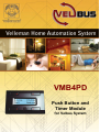
VMB4PD
Push Button and
Timer Module
for Velbus System
VMB4PD
1
Push Button and Timer Module for Velbus® System
VMB4PD
Introduction
This unique panel will let you control all of the output modules on the Velbus® system. There is no need to
remember the function of each button, just read the label next to it!
The module also features programmable timing functions to automate daily or weekly button press actions.
The infrared receiver will let you control the module at distance.
Features
Four push buttons and one configuration push button.
Up to 8 commands (2 groups of 4 commands each).
The 2 command groups are directly callable through the configuration push button.
Automatic switchover to the first group of commands after 15 seconds of inactivity.
Push button debounce: 65ms.
Possibility for each push button to react only when maintaining pressed (1s, 2s of 3s).
Adjustable push button backlight: off – low dimming – high dimming – max. intensity.
LED indication for each push button: slow, fast, very fast blinking or continuously on.
Remote Control:
Built-in IR receiver for use with the Velbus®
Can be used with the VMBIRTS IR remote stick
IR modulation: RECS80
Transmitter/receiver range: ±10m
LCD display:
2 lines of 16 characters
White backlight
Adjustable backlight: off – low dimming – high dimming – max. intensity.
Possibility to automatically adjust the backlight intensity (twice a day).
Adjustable contrast through configuration menu.
Labelling on the display for each command, 2 lines of 16 characters for each label
Configuration:
Adjustable display contrast and backlight.
Adjustable push button backlight.
Adjustable command reaction time (at once, 1, 2 or 3 seconds)
Command labelling.
Module address configuration (256 possible addresses).
Clock configuration.
Mode configuration (command panel only, command panel with timer or command panel with timer for the
2nd group of commands).
Input and modification of the timer program steps.
Timer activation or deactivation for a specific push button.
Configuration menu will automatically close after 25 seconds of inactivity.
Clock:
Built-in clock with day display.
Setting one clock will adjust all other clocks on the Velbus® system.
Possibility to configure one clock as main clock – all other clocks will run right.
Timer:
Programmable timer functions for push button command automation.
Up to 20 program steps.
Each program step can automate up to 8 commands.
VMB4PD
2
Power Supply:
Required power voltage: 12 to 18VDC.
Consumption:
backlight off: 13mA LEDs off / 15mA LEDs on
backlight lowly dimmed: 14mA LEDs off / 16mA LEDs on
backlight highly dimmed: 18mA LEDs off / 19mA LEDs on
backlight max. intensity: 26mA LEDs off / 27mA LEDs on
Max. consumption (all LEDs activated and backlight max. intensity): 27mA.
Power supply LED indication.
9V-battery connection (clock back-up power).
Back-up battery power consumption: 15mA.
Battery not included.
Dimensions:
Push button module (L x W x H): 66 x 44 x 30 mm
Push button module with frame (L x W x H): 118 x 80 x 30 mm
Frame not included.
VELBUS:
2-wire communication for VELBUS data and 2 wires for power
Data transfer: 16.6kbit/s
Serial data protocol: CAN (Controller Area Network)
Short-circuit proof (towards negative or positive of power)
Bus error indication: 2 x short flash of the indication LED
Self restoring after 25 seconds in case of a bus error
Possibility to assign a name (max. 15 characters) and a reaction time (65ms, 1s, 2s of 3s) which can be
saved in the non-volatile memory.
The command labels are displayed on the LCD. These labels consist of 2 lines of 16 characters each and
will also be saved in the non-volatile memory.
When pressing, maintaining pressed and releasing a push button, an instruction is being sent.
Instructions will be accepted when setting the backlight, switching the indication LEDs on and off, slow,
fast or very fast blinking of the indication LEDs, calling up the module type, the push button names and
when reading from or writing to the non-volatile memory.
The module can respond with the module type, the push button name or the contents from the memory.
VMB4PD
3
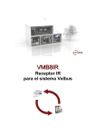
Connection
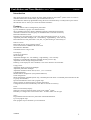
For connection between the modules, use twisted pair cable (ex. EIB 2x2x0.8mm2, UTP 8x0.51mm - CAT5
or other). Use minimum 0.5mm² cable. For long wiring (>50m) or if a lot of modules ( > 10) are connected
to one wire, use 1mm² cable. Connect the 12-18Vdc (mind the polarity) and connect the bus wires (mind the
polarity).
VMB4PD
L
H
H
L
BUS
+
12V
-
-12V+
BUS
TWISTED
PAIR
(0.5mm 2 )
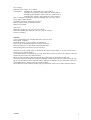
Connect a 9V battery (via the included cable) if you desire to power the clock in case of a power failure.
Velbus
H
L
+
12V power supply
-
J
+
-
Open
9V backup
battery
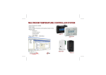
Hint: for advanced level only!
Solder island “J” when using a back-up battery in order to feed the battery.
Velbus
H
L
+
12V power supply
-
J
+
-
Closed
Rechargeable
9V backup
battery
WARNING: NEVER use a regular battery (non rechargeable) when soldering island “J” to avoid
risks of explosion.
VMB4PD
4
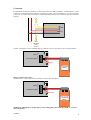
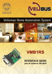
Termination:
Velbus®
transmission LED
Velbus®
reception LED
Termination
H
L
+
12V power
supply
Velbus
+
-
9V back-up
battery
Velbus® power LED
If the module is connected at the start or end of a cable on the VELBUS, place the ‘TERM’ jumper.
Remove the jumper in all other cases.
If different cable wiring topologies (tree, star, loop, ...) are used, place a jumper on the end module of the
longest cable only, NOT on each end point.
VMB4PD
5
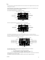
Use
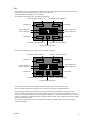
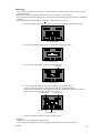
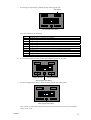
The module consists of 4 push buttons with corresponding LED indication and one configuration push
button. The label for each push button is displayed on the LCD.
This module allows defining up to 8 commands.
The module will display the first 4 commands by default:
Indication LED command 1
Indication LED command 2
Command 1
Command 2
Label command 2
Label command 4
Label command 1
Label command 3
Command 3
Command 4
Indication LED command 3
Indication LED command 4
Configuration push button
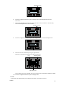
Push the configuration button to switch to the next four commands:
Indication LED command 5
Indication LED command 6
Command 5
Command 6
Label command 6
Label command 8
Label command 5
Label command 7
Command 7
Command 8
Indication LED command 7
Indication LED command 8
Configuration push button
The module switches back to the default command display after 15 seconds of inactivity.
You can switch between the two displays at any time by pressing the configuration button.
When pressing, maintaining pressed and releasing a push button, an instruction is being sent on the
Velbus®. These messages identify which push button has been pressed, maintained pressed or released.
Other modules (relay modules, blind control modules, dimmers...) connected to the Velbus® will react and
answer by resending a command message to the push button module. This command will switch off, light
of blink the indication LEDs.
How a specific push button will control a particular module is explained in the learning mode of the
concerning modules.
VMB4PD
6
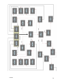
Configuration
When using the module in the Velbus® system for the first time, configure:
• contrast
• backlight
• push button backlight
• clock
• address
• labels
• reaction time
• mode
• timer
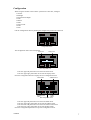
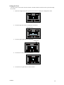
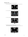
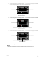
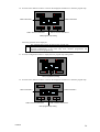
Call the configuration menu by holding the configuration pressed for 4 seconds.
Configuration button
The configuration menu will be displayed.
Clock menu
Display menu
Next configuration menu
Press the upper left push button to activate the clock menu.
Press the upper right push button to activate the display menu.
Press the configuration button to display the next configuration menu.
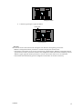
Mode menu
Address menu
Reaction time
Label
menu
editor
Quit configuration menu
Press the upper left push button to activate the mode menu.
Press the upper right push button to activate the address menu.
Press the lower left push button to activate the reaction time menu.
Press the lower right push button to activate the label editor.
Press the configuration push button to quit the configuration menu.
VMB4PD
7
•
•
•
•
•
Remarks:
In configuration mode pressing the push buttons will no more be sent through the Velbus®.
All settings will be saved in the module (even with a power failure).
The first configuration menu shows menus “Prog” and “Timer on/off” when the timer is activated.
The module will automatically quit the configuration mode after 30 seconds of inactivity.
Hold the configuration button pressed for 8 seconds to display the configuration menu which allows
modifying contrast and backlight.
VMB4PD
8
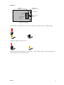
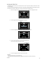
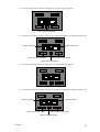
Setting the Display Contrast
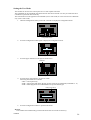
1.
Hold the configuration button pressed for 4 seconds to display the configuration menu.
Configuration button
2.
Press the upper right button to display the display menu.
Display menu
3.
Adjust the display contrast using the two upper buttons.
Less contrast
More contrast
Next display menu
4.
Press the configuration button repeatedly to quit the display menu.
Remarks:
• Hold the configuration button pressed for 8 seconds to display the contrast mode.
• The display contrast may be set too low if experiencing a blank display. Hold the configuration button
pressed for 8 seconds to switch the module to the configuration menu which allows modifying contrast.
Hold the upper right push button pressed for 3 seconds. The contrast will be set at its maximum.
• The module will automatically quit the configuration mode after 30 seconds of inactivity.
VMB4PD
9
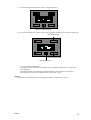
Setting the Display and Push Button Backlight
The backlight intensity can be set according to your preferences (completely off, completely on or
dimmed). The module allows you to automatically modify the intensity twice a day.
The push button backlight intensity can also be set according to your preferences. This is useful when
trying to locate the buttons in a completely dark room.
1.
Hold the configuration button pressed for 4 seconds to display the configuration menu.
Configuration button
2.
Press the upper right button to display the display menu.
Display menu
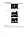
3.
Press the lower buttons to adjust the backlight intensity.
Display backlight
4.
Push button backlight
Press the configuration button to display the next display button.
Next display menu
5.
VMB4PD
Press the upper right button to (de)activate the backlight.
10
Backlight timer on/off
Quit display menu
6.
Press the configuration button to quit the display menu if the backlight timer has been
deactivated.
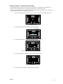
7.
Activate the backlight timer using the upper right button when you desire to automatically
switch the backlight between two intensities.
Backlight timer on/off
8.
Press the configuration button to display the configuration menu for the backlight timer.
Backlight timer configuration menu
9.
Enter the first time and intensity using the upper buttons.
Enter the second time and intensity using the lower buttons.
Time
Time
Backlight intensity
Backlight intensity
Quit display menu
In the example above: the backlight will be set at full intensity at 08h00 and dimmed at 20h00.
10. Press the configuration button to quit the display menu.
Remark:
• The module will automatically quit the display menu after 30 seconds of inactivity.
VMB4PD
11
Setting the Clock
You only need to set the clock from one module. All other modules connected in the system will adopt
the set time.
1.
Hold the configuration button pressed for 4 seconds to display the configuration menu.
Configuration button
2.
Press the upper left button to display the clock menu.
Setting the clock
3.
Press the upper right button to set the day.
Setting the day
4.
Press the lower left button to set the hour.
Setting the hour
5.
VMB4PD
Press the lower right button to set the minutes.
12
Setting the minutes
6.
Confirm by pressing the upper left button.
Confirm time
Next clock menu
Remarks:
The seconds counter starts from 0 when setting the time. Wait for the beginning of a minute
• Hold the configuration button pressed for 8 seconds to display the contrast mode.
• The display contrast may be set too low if experiencing a blank display. Hold the configuration button
pressed for 8 seconds to switch the module to the configuration menu which allows modifying contrast.
Hold the upper right push button pressed for 3 seconds. The contrast will be set at its maximum.
• The module will automatically quit the configuration mode after 30 seconds of inactivity.
VMB4PD
13
Activating the Main Clock
All modules (with clock function) connected onto the Velbus® system must adopt the same time in order
to work properly.
This can be achieved by setting the main clock o none of the connected modules. This module will send
the time over the Velbus® system once every day and synchronize all other clocks.
1.
Hold the configuration button pressed for 4 seconds to display the configuration menu.
Configuration button
2.
Press the upper left button to display the clock menu.
Clock menu
3.
Press the configuration button again to display the next clock menu.
Next clock menu
4.
Press the upper right button to (de)activate the main clock.
The lower line shows the software version.
Main clock on/off
Quit clock menu
5.
Press the configuration button to quit the clock menu.
Remarks:
• Activate the main clock o none module only.
• The module will automatically quit the configuration mode after 30 seconds of inactivity.
VMB4PD
14
Addressing
Every module connected onto the Velbus® system must have a unique address which can be set via the
configuration menu.
Make sure to synchronize the IR transmitter/receiver by setting the correct address.
The final digit represents the address to be entered into the IR transmitter (see manual for the VMBIRTS
transmitter).
Example: push button model address = 26, IR transmitter address must be 6.
1.
Hold the configuration button pressed for 4 seconds to display the configuration menu.
Configuration button
2.
Press the configuration button again to display the configuration menu.
Next configuration menu
3.
Press the upper right button to display the address menu.
Addressing
Quit configuration menu
4.
Press the upper left button to select the left address digit (blinking digit).
Press the upper right button to select the right address digit (blinking digit).
Hold the lower left button pressed and press the lower right button to modify the selected
address digit. Select an address between “00” and “FE”.
Left address digit
Modifying address
Left address digit
Modifying address digit
Quit address menu
5.
Press the configuration button to quit the address menu.
Remarks:
• Make sure every module has a unique address.
• The module will automatically quit the configuration mode after 30 seconds of inactivity.
VMB4PD
15
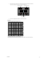
Modifying the Labels
It is possible to label all commands so as to explain their function.
1.
Hold the configuration button pressed for 4 seconds to display the configuration menu.
Configuration button
2.
Press the configuration button again to display the configuration menu.
Next configuration menu
3.
Press the lower right button to display the label editor.
Label editor
Quit configuration menu
4.
Move the cursor to the left or to the right using the two upper push buttons.
Select the character using the two lower push buttons.
Press the configuration button to display the second set of commands (commands 5 to 8).
Cursor to the left
Cursor to the right
Select character
Select character
Display second set of commands
VMB4PD
16
5.
Move the cursor to the left or to the right using the two upper push buttons.
Select the character using the two lower push buttons.
Cursor to the left
Select character
Cursor to the right
Select character
Quit label editor
6.
Press the configuration button to quit the label editor.
Remarks:
• Following characters can be chosen from:
0
@
P
`
p
!
1
A
Q
a
q
"
2
B
R
b
r
#
3
C
S
c
s
$
4
D
T
d
t
%
5
E
U
e
u
&
6
F
V
f
v
'
7
G
W
g
w
(
8
H
X
h
x
)
9
I
Y
i
y
*
:
J
Z
j
z
+
;
K
[
k
{
,
<
L
¥
l
|
=
M
]
m
}
.
>
N
^
n
/
?
O
_
o
• Hold a button pressed to scroll.
• Scrolling will stop with a space character.
• The module will automatically quit the label editor after 30 seconds of inactivity.
VMB4PD
17
Setting the Reaction Time
All commands have a short reaction time (65ms) by default. This reaction time can be set at 1, 2 or 3
seconds.
1.
Hold the configuration button pressed for 4 seconds to display the configuration menu.
Configuration button
2.
Press the configuration button again to display the next configuration menu.
Next configuration menu
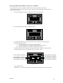
3.
Press the lower left push button to display the reaction time menu.
Setting reaction
time
Quit configuration menu
4.
Press the lower buttons to set a reaction time of 0, 1, 2 or 3 seconds for the displayed command.
Press the configuration button to display the next configuration menu.
Label command 1
Label command 2
Modify reaction time command 1
Modify reaction time command 2
Next reaction time menu
VMB4PD
18
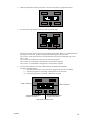
5.
Press the lower buttons to set a reaction time of 0, 1, 2 or 3 seconds for the displayed command.
Press the configuration button to display the next configuration menu.
Label command 4
Label command 3
Modify reaction time command 3
Modify reaction time command 4
Next reaction time menu
6.
Press the lower buttons to set a reaction time of 0, 1, 2 or 3 seconds for the displayed command.
Press the configuration button to display the next configuration menu.
Label command 6
Label command 5
Modify reaction time command 5
Modify reaction time command 6
Next reaction time menu
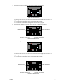
7.
Press the lower buttons to set a reaction time of 0, 1, 2 or 3 seconds for the displayed command.
Label command 8
Label command 7
Modify reaction time command 7
Modify reaction time command 8
Quit reaction time menu
8.
Press the configuration button to quit the reaction time menu.
Remarks:
• The module will automatically quit the reaction time menu after 30 seconds of inactivity.
VMB4PD
19
Setting the User Mode
The module can be used as a control panel or as a control panel with timer.
The commands can be automated if the timer function has been activated. It is like you would activate a
command at a particular time of the day.
The timer function can be applied to all commands (Timer mode:8CH) or to the second set of commands
only (Timer mode:4CH).
1.
Hold the configuration button pressed for 4 seconds to display the configuration menu.
Configuration button
2.
Press the configuration button again to display the configuration menu.
Next configuration menu
3.
Press the upper left button to display the mode menu.
Modemenu
Quit configuration menu
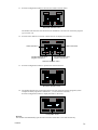
4.
Press the upper right button to set the user mode.
Following user modes are available:
“OFF”: control panel only
“4CH”: control panel with timer function for the second set of commands (commands 5 ...8)
“8CH”: bedieningspaneel met schakelklokfunctie op alle bedieningen
Modify mode settings
Quit mode menu
5.
Press the configuration button to quit the mode menu.
Remark:
• The module will automatically quit the mode menu after 30 seconds of inactivity.
VMB4PD
20
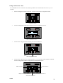
Programming the Timer
Programming can only be done if the timer function was selected in the user mode.
The commands can be automated via the timer function. It is like you would activate a command at a
particular time of the day. Twenty program steps can be programmed; each step has a programmable time
(day, hour and minutes) and command.
1.
Hold the configuration button pressed for 4 seconds to display the configuration menu.
Configuration button
2.
Press the lower left button to display the program menu.
Program menu
3.
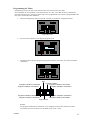
The display shows the first program step (program number, time and a view of the automated
commands).
Day
Program indication command 5
Program indication command 1
Program number
Program indication command 2
Program indication command 6
Program indication command 3
Program indication command 8
Program indication command 7
Program indication command 4
Program time
Remark:
The program indications for commands 1 to 4 disappear when the timer function has been
activated only for the second set of commands (Timer mode: 4CH).
VMB4PD
21
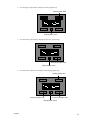
4.
Press the upper right button to display the next program step.
Next program step
Quit program menu
5.
Press the lower right button to display the previous program step.
Previous program step
Quit program menu
6.
Press the lower left button to modify the displayed program step.
Next program step
Modify program step
Previous program step
Quit program menu
VMB4PD
22
7.
Press the upper right button to modify the day of the program step.
Day setting
Next program step setting
You can choose from the following:
Mo
Tu
We
Th
Fr
Sa
Su
Sa&Su
Mo-Fr
Mo-Sa
Mo-Su
Never
8.
Program step is executed every Monday
Program step is executed every Tuesday
Program step is executed every Wednesday
Program step is executed every Thursday
Program step is executed every Friday
Program step is executed every Saturday
Program step is executed every Sunday
Program step is executed every Saturday and Sunday
Program step is executed every day except on Saturday and Sunday
Program step is executed every day except on Sunday
Program step is executed every day
Program step will not be executed
Press the lower buttons to enter the time the program step must be executed.
Setting the hour
Setting the minutes
Next program step setting
9.
Press the configuration button to display the next program step setting menu.
Next program step setting
Go to section 14 if the timer function has only been activated for the second set of commands
(Timer mode: 4CH).
VMB4PD
23
10. Press the lower buttons to add or to remove the displayed command to or from the program step.
Label command 2
Label command 1
Add or remove command 1
Add or remove command 2
Next program step setting
Following symbols can be displayed:
The command has not been accepted in the program step
The command has been accepted in the program step. The push button will be
activated automatically on the time (day, hour, minutes) programmed and
memorized into the program step.
11. Press the configuration button to display the next program step setting menu.
Next program step setting
12. Press the lower buttons to add or to remove the displayed command to or from the program step.
Label command 3
Label command 4
Add or remove command 3
Add or remove command 4
Next program step setting
VMB4PD
24
13. Press the configuration button to display the next program step setting menu.
Next program step setting
14. Press the lower buttons to add or to remove the displayed command to or from the program step.
Label command 5
Label command 6
Add or remove command 5
Add or remove command 6
Next program step setting
15. Press the configuration button to display the next program step setting menu.
Next program step setting
16. Press the lower buttons to add or to remove the displayed command to or from the program step.
Label command 7
Label command 8
Add or remove command 7
Add or remove command 8
Return to general display
VMB4PD
25
17. Press the configuration button to return to the general display
Return to general display
18. Press the lower buttons to add or to remove the displayed command to or from the program step.
Next program step
Previous program step
Quit program menu
Let’s explain the example above:
Command 1 will be executed every Monday morning at 08h30, commands 3, 5 and 8 will be
activated briefly.
Program indications for commands 1 through 4 disappear if the timer function has been
activated for the second set of commands only (Timer mode: 4CH).
Remark:
• The module will automatically quit the program menu after 30 seconds of inactivity.
VMB4PD
26
Activating and Deactivating the Timer per Command
The program will only be executed if the timer function for the command is activated.
Deactivate the timer for the commands you do not want to be executed during a certain period (e.g.
during vacation period).
1.
Press the configuration button to display the second set of commands.
Configuration button
2.
Press the configuration button to display the clock.
Configuration button
3.
The module displays the current time and an overview of the active timer programs.
The timer indication means:
“ ”: the command will not be used in the timer program.
“-”: the timer program for a particular command will not be executed.
“”: the timer program for a particular command is activated.
The timer indications for commands 1 through 4 disappear if the timer function has been
activated for the second set of commands only (Timer mode: 4CH).
Timer indication command 5
Timer indication command 2
Timer indication command 1
Timer indication command 3
Timer indication command 6
Timer indication command 8
Timer indication command 7
Timer indication command 4
Configuration button
In the example above:
Commands 1, 3, 5 and 8 will be used in the program but the program will not be executed.
VMB4PD
27
4.
Hold the configuration button pressed for 4 seconds to display the configuration menu.
Configuration button
5.
Press the lower right button to enter the timer activation menu.
Timer activation menu
The timer activation menu is possibly not available which means there is no command used in
the program. In this case, press the configuration button again to exit the menu.
Go to section 10 the timer function is activated for the second set of commands only (Timer
mode: 4CH).
Go to section 8 if commands 1 and 2 are not used in the program.
Go to section 10 if commands 1 through 4 are not used in the program.
Go to section 12 if commands 1 through 6 are not used in the program.
6.
Press the lower buttons to activate or deactivate for the displayed commands.
The timer indication means:
“ ”: the command will not be used in the timer program and cannot be modified.
“-”: the timer program for a particular command will not be executed.
“”: the timer program for a particular command is activated.
Label command 1
Label command 2
Activate/deactivate timer
program command 1
Activate/deactivate timer
program command 2
Next timer activation menu
VMB4PD
28
7.
Press the configuration button to enter the next timer activation menu.
Next timer activation menu
The module exits the timer activation menu if commands 3 through 8 are not used in the
program (go to section 14).
Go to section 10 if commands 3 and 4 are not used in the program.
Go to section 12 if commands 3 through 6 are not used in the program.
8.
Press the lower buttons to activate or deactivate for the displayed commands.
Label command 3
Label command 4
Activate/deactivate timer
program command 3
Activate/deactivate timer
program command 4
Next timer activation menu
9.
Press the configuration button to enter the next timer activation menu.
Next timer activation menu
The module exits the timer activation menu if commands 5 through 8 are not used in the
program (go to section 14).
Go to section 12 if commands 5 and 6 are not used in the program.
10. Press the lower buttons to activate or deactivate for the displayed commands.
Label command 5
Label command 6
Activate/deactivate timer
program command 5
Activate/deactivate timer
program command 6
Next timer activation menu
VMB4PD
29
11. Press the configuration button to enter the next timer activation menu.
Next timer activation menu
The module exits the timer activation menu if commands 7 and 8 are not used in the program
(go to section 14).
12. Press the lower buttons to activate or deactivate for the displayed commands.
Label command 7
Label command 8
Activate/deactivate timer
program command 7
Activate/deactivate timer
program command 8
Quit timer activation menu
13. Press the configuration button to quit the timer activation menu.
Quit timer activation menu
14. The module displays the current time and an overview of the active timer programs (in this
example the timer program for commands 1, 3, 5 and 8 will be executed).
Press the configuration button to display the labels or the clock.
Configuration button
Remark:
The module will automatically quit the timer activation menu after 30 seconds of inactivity.
VMB4PD
30
Use
The timer function is deactivated by default and can be activated via the configuration menu (see section
“Setting the User Mode”).
The module consists of 4 push buttons with corresponding LED indication and one configuration push
button. The label for each push button is displayed on the LCD.
This module allows defining up to 8 commands.
The module will display the first 4 commands by default.
Indication LED command 1
Indication LED command 2
Command 1
Command 2
Label command 2
Label command 4
Label command 1
Label command 3
Command 3
Command 4
Indication LED command 3
Indication LED command 4
Configuration button
Press the configuration button to switch to the next set of commands:
Indication LED command 5
Indication LED command 6
Command 5
Command 6
Label command 6
Label command 8
Label command 5
Label command 7
Command 7
Command 8
Indication LED command 7
Indication LED command 8
Configuration button
The module will automatically switch to the default command set after 15 seconds of inactivity.
Press the configuration button again to return to the default command set (if the timer is deactivated) or to
the display the current timer (if the timer is activated).
Indication LED command 1
Indication LED command 2
Command 1
Command 2
Timer indication command 5
Timer indication command 5
Timer indication command 1
Timer indication command 3
Timer indication command 6
Timer indication command 8
Timer indication command 4
Command 4
Timer indication command 7
Command 3
Indication LED command 3
Indication LED command 4
Configuration button
The push buttons and their indication LED are configured in the first set of commands.
The timer indication means:
“ ”: the command will not be used in the timer program.
“-”: the timer program for a particular command will not be executed.
“”: the timer program for a particular command is activated.
Timer indicators for commands 1 through 4 disappear if the timer function is activated for the seconds set
of commands only (Timer mode: 4CH).
It is possible to switch between the different displays by pressing the configuration button.
VMB4PD
31
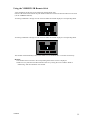
Using the VMBIRTS IR Remote Stick
All 8 commands can directly be activated using the IR remote stick.
Point the IR remote stick towards the push button module and activate the desired channel on the stick
(see the VMBIRTS manual).
Activating commands 1 through 4 on the stick will make the module display the corresponding labels.
Activating commands 5 through 8 on the stick will make the module display the corresponding labels.
The module will automatically return to the default set of commands after 15 seconds of inactivity.
Remark:
• The module will not switch to the corresponding labels if the current is displayed.
• Make sure to synchronize the IR transmitter/receiver by setting the correct address. Refer to
“Addressing” and the transmitter user manual.
VMB4PD
32
Troubleshooting
No display:
• The display contrast is too low. Hold the configuration button pressed for 3 seconds to switch the
module to the configuration menu which allows modifying contrast. Hold the upper right push button
pressed for 8 seconds. The contrast will be set at its maximum.
• Selection of blank characters during labelling. Press the configuration button a couple of times until a
blinking cursor is displayed in the upper left corner. Enter your label using the 4 push buttons.
• Remove the power supply during min. 10 seconds.
The remote control stick does not function:
• Drained batteries in the transmitter. Replace the batteries.
• Addresses of the transmitter/receiver are not synchronized. See “Addressing” and the transmitter’s
notice.
VMB4PD
33
VMB4PD
34
VMB4PD
35