1
Using This Retrofit Guide
This document is best viewed with Adobe Reader 6.0. To obtain the latest version of Adobe Reader, visit
http://www.adobe.com
Specification sheets on Watlow product may be obtained at http://www.watlow.com/literature/specsheets/
User Manuals on Watlow product may be obtained at http://www.watlow.com/literature/prodtechinfo/
Additional information on other Watlow products may be obtained by visiting http://www.watlow.com/
To locate a controller, search on the part number such as 965A-1CD0-00RG. Use the Help feature in Adobe Reader on
how to search documents.
If there are multiple listings, then the retrofit is conditional upon field use. Select the appropriate selection. The User’s
Manual is included at the bottom of this document when available.
Before selecting a replacement controller:
1.
Know the application.
• Temperature range
• Sensor type
• Is the sensor upgradable if required?
• Additional input requirements – remote set points, secondary sensor or events
• Output required – control, alarm, event
• Is the power-switching device upgradable?
• Operating voltage of controller
• Mounting requirements – panel space
• Is a safety limit device required?
2.
Know the product.
• Inputs – type and number of
• Control function – direct (cool) or reverse (heat)
• Outputs – switched DC, SSR, or mechanical relay
• Communication requirements
• Which control features are required? (cascade, slidewire, differential, remote control, other)
3.
Use your best judgment for selecting a replacement controller. All applications require close examination of input,
output and the control mode needs to have the controller function properly.
4.
Safety: Remember to make sure all redundant safety equipment is in place and working when retrofitting equipment.
If a system has been retrofitted without the proper safety equipment, you could be liable if an accident occurs.
This is only a guide to replacement controllers. If you have doubts, please call (507) 454-5300
and ask for technical support or email [email protected]. We’re here to help. The
suggested replacement will differ in fit and form. Please review the replacement controller
specifications for suitability. Carefully check the notes for additional information that may
apply.
Your comments or suggestions on the Retrofit Guide are welcome. Please send comments or corrections to: Technical
Writer, Watlow Controls, 1241 Bundy Boulevard, P.O. Box 5580, Winona, MN 55987-5580; phone (507) 454-5300; fax
(507) 452-4507. This Retrofit Guide is copyrighted by Watlow Winona, Inc., © February 2004 with all rights reserved. (1455)
Abbreviation & Terminology
(as used in this document)
0.5 – 0.5 amperes of current switching capability
2A – 2 amperes of current switching capability
5A - 5 amperes of current switching capability
10A – 10 amperes of current switching capability
15A – 15 amperes of current switching capability
12-24 – Supply voltage can be between 12 to 24 Volts
100-240 – Supply voltage can be between 100 to 240 Volts
100 ohm DIN – refers to 100-ohm platinum RTD that has a DIN curve.
100 ohm JIS – refers to 100-ohm platinum RTD that has a JIS curve.
1/32 DIN – Deutsche Industrial Norm standard for panel mounted controller, hole size is cut to 1.78”w x 0.88”h.
1/16 DIN – Deutsche Industrial Norm standard for panel mounted controller, hole size is cut to 1.78”w x 1.77”h.
1/8V DIN – Deutsche Industrial Norm standard for panel mounted controller, hole size is cut to 1.78”w x 3.63”h.
1/8H DIN – Deutsche Industrial Norm standard for panel mounted controller, hole size is cut to 3.63”w x 1.77”h”
1/8S DIN – Deutsche Industrial Norm standard for panel mounted controller, hole size is cut to 2.68”w x 2.68”h.
¼ DIN – Deutsche Industrial Norm standard for panel mounted controller, hole size is cut to 3.63”w x 3.63”h.
Action – determines the direction of control. Heat (reverse acting) or Cool (direct acting).
Auto Reset – the limit will automatically reset on a power cycle but requires manual reset on limit trip.
Cascade – a control algorithm in which the output of one control loop provides a set point for another loop. The second
loop, in turn, determines the control action.
Ch – Channel refers to an analog input. There are single and dual channel controllers.
Control Mode – the method that a controller uses to switch the outputs such as PID, ON/OFF, and Manual.
Differential - control algorithm in which the output is based on the difference of the inputs plus set point.
DIN – Deutsche Industrial Norm, a set of technical, scientific and dimensional standards developed in Germany. RTD
sensors with the DIN curve change resistance at a rate of 0.00385 ohms/ohms/C.
DIN Rail – standard DIN EN50022 mounting method for attaching devices onto a metal rail.
Fixed – refers to a set point that is fixed at one value.
High Limit - device will deactivate output on a temperature rise above set point.
Inductive Load – any device that has a wire winding such as solenoids, electromechanical relays or transformers.
Input – refers to the sensor types that may be connected.
Integral – the set point in integral (on board) to the controller.
JIS – Joint Industrial Standards, a set of technical, scientific and dimensional standards developed in Japan. RTD sensors
with the JIS curve change resistance at a rate of 0.00396 ohms/ohms/C.
Line Voltage – the voltage required powering the electronics of the controller.
Low Limit - device will deactivate output on a temperature drop below set point.
On/Off – a method of control that turns the output full on until set point is reached and then off until the process error
exceeds the hysteresis.
Open Brd – the form factor of this controller is an open circuit board mounted on four standoffs.
Manual Reset – the limit must be reset on a power cycle and requires manual reset on limit trip.
Multi RSP – multiple remote set potentiometers were supported. Each allowed the set point to be selected and adjusted.
Relay – refers to an electromechanical relay.
Remote – set point is adjusted using a remote potentiometer.
Panel – the form factor of this controller is mounted through a hole cut in the panel.
PI – Proportional and Integral, a control mode with two functions: proportional action dampens the systems response,
and integral corrects for droop.
PID – Proportional, Integral, and Derivative, a control mode with three functions: proportional action dampens the
systems response, integral corrects for droop, and derivative prevents overshoot and undershoot.
Potted – the circuit board and electronics are encased in epoxy.
Proc – Process input may accept 0-5, 1-5, 0-10 volts or 0-20 and 4-20 mA.
Profiling – Controller will perform a sequence of programmed steps.
Programmable – The feature is changeable in the field through jumpers and/or parameter selection.
RTD – Resistance Temperature Detector, a sensor that is 100 ohms at 0 degrees C and made of platinum material.
SSR – Solid State Relay, these devices will switch AC voltage only and require a load to latch on.
Sw DC – Switched DC, a time proportioning DC output used to drive DC input solid state relays.
t/c – Thermocouple sensor device made by joining two dissimilar metals whose standards is identified by a letter.
Temp Range – the range over which the controller could have the set point adjustment.
Thermistor – a sensor that changes resistance as the temperature changes. Similar but not the same as an RTD.
Universal – Input can be a thermocouple, 100 ohm DIN RTD or process (volts or milliamperes)
VAC – Volts Alternating Current
VAC/DC- Volts Alternating Current or Direct Current
VDC – Volts Direct Current
VTB Sw DC – Variable Time Base Switched Direct Current, a time proportioning DC output where the cycle time is
variable.
These notes are used to signify areas of concern in changing to a retrofit choice. These notes are also printed at the end
of the retrofit listing.
Note 1: Retrofit controller requires a substitution of a 100 Ohm RTD sensor for the thermistor.
Note 2: Mounting and dimensions of retrofit controller are different. Verify that sufficient panel space and depth is
available.
Note 3: Retrofit controller outputs are different. Add external interposing mechanical or solid state relay if applicable.
Note 4: Retrofit controller has a programmable, not fixed set point. Lock set point using controller's lockout parameter.
Note 5: For DIN rail mounting or sub-panel mounting, purchase DIN rail adapter p/n 0822-0586-P001 for 1/32 DIN or
p/n 0822-0586-P002 for 1/16 DIN.
Note 6: Add a suppressor, Watlow p/n 0804-0147-0000, for inductive loads.
Note 7: Retrofit does not have equivalent action (as example, no manual reset)
Note 8: Retrofit controller does not have dual dial scale.
Note 9: Hardware lockout is not available on retrofit.
Note 10: Retrofit controller does not have user selectable line voltage.
Note 11: Retrofit does not support remote set point or retransmit. Check if pins 13, 14, 15 or 16 have termination. If
wires are on these pins, select a different retrofit.
Note 12: Retrofit controller does not have user selectable control action.
Note 13: Solid state sensor required for humidity. See http://www.vaisala.com
Note 14: Retrofit controller does not have user selectable control mode.
Note 15: Use auxiliary event board A007-1732-F4B8
Note 16: Retrofit communications are different, consult specifications.
Note 17: Verify retrofit input range matches application.
Series 922
Line Voltage
Input
Control Mode
Action
Output
Set Point
Mounting
922A-1BB0-A000
115/230 VAC
RTD/RTD
Progammable
Progammable
Dual 0.5A SSR/0.5A SSR
Profiling
1/4 DIN
F4DH-KKKK-01RG
6
922A-1BB0-B000
115/230 VAC
RTD/RTD
Progammable
Progammable
Dual 0.5A SSR/0.5A SSR
Profiling
1/4 DIN
F4DH-KKKK-01RG
6, 16
922A-1BB0-C000
115/230 VAC
RTD/RTD
Progammable
Progammable
Dual 0.5A SSR/0.5A SSR
Profiling
1/4 DIN
F4DH-KKKK-01RG
6, 16
922A-1CC0-A000
115/230 VAC
RTD/RTD
Progammable
Progammable
Dual Sw dc/Sw dc
Profiling
1/4 DIN
F4DH-CCCC-01RG
922A-1CC0-B000
115/230 VAC
RTD/RTD
Progammable
Progammable
Dual Sw dc/Sw dc
Profiling
1/4 DIN
F4DH-CCCC-01RG
16
922A-1CC0-C000
115/230 VAC
RTD/RTD
Progammable
Progammable
Dual Sw dc/Sw dc
Profiling
1/4 DIN
F4DH-CCCC-01RG
16
922A-1FB0-A000
115/230 VAC
RTD/RTD
Progammable
Progammable
Dual 4-20MA/0.5A SSR
Profiling
1/4 DIN
F4DH-FKFK-01RG
6
922A-1FB0-B000
115/230 VAC
RTD/RTD
Progammable
Progammable
Dual 4-20MA/0.5A SSR
Profiling
1/4 DIN
F4DH-FKFK-01RG
6, 16
922A-1FB0-C000
115/230 VAC
RTD/RTD
Progammable
Progammable
Dual 4-20MA/0.5A SSR
Profiling
1/4 DIN
F4DH-FKFK-01RG
6, 16
922A-2BB0-A000
115/230 VAC
RTD/Proc
Progammable
Progammable
Dual 0.5A SSR/0.5A SSR
Profiling
1/4 DIN
F4DH-KKKK-01RG
6
922A-2BB0-B000
115/230 VAC
RTD/Proc
Progammable
Progammable
Dual 0.5A SSR/0.5A SSR
Profiling
1/4 DIN
F4DH-KKKK-01RG
6, 16
922A-2BB0-C000
115/230 VAC
RTD/Proc
Progammable
Progammable
Dual 0.5A SSR/0.5A SSR
Profiling
1/4 DIN
F4DH-KKKK-01RG
6, 16
922A-2CC0-A000
115/230 VAC
RTD/Proc
Progammable
Progammable
Dual Sw dc/Sw dc
Profiling
1/4 DIN
F4DH-CCCC-01RG
922A-2CC0-B000
115/230 VAC
RTD/Proc
Progammable
Progammable
Dual Sw dc/Sw dc
Profiling
1/4 DIN
F4DH-CCCC-01RG
16
922A-2CC0-C000
115/230 VAC
RTD/Proc
Progammable
Progammable
Dual Sw dc/Sw dc
Profiling
1/4 DIN
F4DH-CCCC-01RG
16
922A-2FB0-A000
115/230 VAC
RTD/Proc
Progammable
Progammable
Dual 4-20MA/0.5A SSR
Profiling
1/4 DIN
F4DH-FKFK-01RG
6
922A-2FB0-B000
115/230 VAC
RTD/Proc
Progammable
Progammable
Dual 4-20MA/0.5A SSR
Profiling
1/4 DIN
F4DH-FKFK-01RG
6, 16
922A-2FB0-C000
115/230 VAC
RTD/Proc
Progammable
Progammable
Dual 4-20MA/0.5A SSR
Profiling
1/4 DIN
F4DH-FKFK-01RG
6, 16
922A-3BB0-A000
115/230 VAC
T t/c/Proc
Progammable
Progammable
Dual 0.5A SSR/0.5A SSR
Profiling
1/4 DIN
F4DH-KKKK-01RG
6
922A-3BB0-B000
115/230 VAC
T t/c/Proc
Progammable
Progammable
Dual 0.5A SSR/0.5A SSR
Profiling
1/4 DIN
F4DH-KKKK-01RG
6, 16
922A-3BB0-C000
115/230 VAC
T t/c/Proc
Progammable
Progammable
Dual 0.5A SSR/0.5A SSR
Profiling
1/4 DIN
F4DH-KKKK-01RG
6, 16
922A-3CC0-A000
115/230 VAC
T t/c/Proc
Progammable
Progammable
Dual Sw dc/Sw dc
Profiling
1/4 DIN
F4DH-CCCC-01RG
922A-3CC0-B000
115/230 VAC
T t/c/Proc
Progammable
Progammable
Dual Sw dc/Sw dc
Profiling
1/4 DIN
F4DH-CCCC-01RG
16
922A-3CC0-C000
115/230 VAC
T t/c/Proc
Progammable
Progammable
Dual Sw dc/Sw dc
Profiling
1/4 DIN
F4DH-CCCC-01RG
16
115/230 VAC
T t/c/Proc
Progammable
Progammable
Dual 4-20MA/0.5A SSR
Profiling
1/4 DIN
F4DH-FKFK-01RG
6
922A-3FB0-B000
115/230 VAC
T t/c/Proc
Progammable
Progammable
Dual 4-20MA/0.5A SSR
Profiling
1/4 DIN
F4DH-FKFK-01RG
6, 16
922A-3FB0-C000
115/230 VAC
T t/c/Proc
Progammable
Progammable
Dual 4-20MA/0.5A SSR
Profiling
1/4 DIN
F4DH-FKFK-01RG
6, 16
922A-4BB0-A000
115/230 VAC
Proc/Proc
Progammable
Progammable
Dual 0.5A SSR/0.5A SSR
Profiling
1/4 DIN
F4DH-KKKK-01RG
6
922A-4BB0-B000
115/230 VAC
Proc/Proc
Progammable
Progammable
Dual 0.5A SSR/0.5A SSR
Profiling
1/4 DIN
F4DH-KKKK-01RG
6, 16
922A-4BB0-C000
115/230 VAC
Proc/Proc
Progammable
Progammable
Dual 0.5A SSR/0.5A SSR
Profiling
1/4 DIN
F4DH-KKKK-01RG
6, 16
922A-4CC0-A000
115/230 VAC
Proc/Proc
Progammable
Progammable
Dual Sw dc/Sw dc
Profiling
1/4 DIN
F4DH-CCCC-01RG
922A-4CC0-B000
115/230 VAC
Proc/Proc
Progammable
Progammable
Dual Sw dc/Sw dc
Profiling
1/4 DIN
F4DH-CCCC-01RG
16
922A-4CC0-C000
115/230 VAC
Proc/Proc
Progammable
Progammable
Dual Sw dc/Sw dc
Profiling
1/4 DIN
F4DH-CCCC-01RG
16
922A-4FB0-A000
115/230 VAC
Proc/Proc
Progammable
Progammable
Dual 4-20MA/0.5A SSR
Profiling
1/4 DIN
F4DH-FKFK-01RG
6
922A-4FB0-B000
115/230 VAC
Proc/Proc
Progammable
Progammable
Dual 4-20MA/0.5A SSR
Profiling
1/4 DIN
F4DH-FKFK-01RG
6, 16
922A-4FB0-C000
115/230 VAC
Proc/Proc
Progammable
Progammable
Dual 4-20MA/0.5A SSR
Profiling
1/4 DIN
F4DH-FKFK-01RG
6, 16
922A-5BB0-A000
115/230 VAC
T t/c/T t/c
Progammable
Progammable
Dual 0.5A SSR/0.5A SSR
Profiling
1/4 DIN
F4DH-KKKK-01RG
6
922A-5BB0-B000
115/230 VAC
T t/c/T t/c
Progammable
Progammable
Dual 0.5A SSR/0.5A SSR
Profiling
1/4 DIN
F4DH-KKKK-01RG
6, 16
922A-5BB0-C000
115/230 VAC
T t/c/T t/c
Progammable
Progammable
Dual 0.5A SSR/0.5A SSR
Profiling
1/4 DIN
F4DH-KKKK-01RG
6, 16
922A-5CC0-A000
115/230 VAC
T t/c/T t/c
Progammable
Progammable
Dual Sw dc/Sw dc
Profiling
1/4 DIN
F4DH-CCCC-01RG
922A-5CC0-B000
115/230 VAC
T t/c/T t/c
Progammable
Progammable
Dual Sw dc/Sw dc
Profiling
1/4 DIN
F4DH-CCCC-01RG
922A-3FB0-A000
Watlow Controls
7/19/2004
Retrofit
See Notes
Below
Series 922
16
Page 1
Series 922
Line Voltage
Input
Control Mode
Action
922A-5CC0-C000
115/230 VAC
T t/c/T t/c
Progammable
Progammable
Dual Sw dc/Sw dc
Profiling
1/4 DIN
F4DH-CCCC-01RG
115/230 VAC
T t/c/T t/c
Progammable
Progammable
Dual 4-20MA/0.5A SSR
Profiling
1/4 DIN
F4DH-FKFK-01RG
6
922A-5FB0-B000
115/230 VAC
T t/c/T t/c
Progammable
Progammable
Dual 4-20MA/0.5A SSR
Profiling
1/4 DIN
F4DH-FKFK-01RG
6, 16
922A-5FB0-C000
115/230 VAC
T t/c/T t/c
Progammable
Progammable
Dual 4-20MA/0.5A SSR
Profiling
1/4 DIN
F4DH-FKFK-01RG
6, 16
922A-6BB0-A000
115/230 VAC
RTD/RTD
Progammable
Progammable
Dual 0.5A SSR/0.5A SSR
Profiling
1/4 DIN
F4DH-KKKK-01RG
6
922A-6BB0-B000
115/230 VAC
RTD/RTD
Progammable
Progammable
Dual 0.5A SSR/0.5A SSR
Profiling
1/4 DIN
F4DH-KKKK-01RG
6, 16
922A-6BB0-C000
115/230 VAC
RTD/RTD
Progammable
Progammable
Dual 0.5A SSR/0.5A SSR
Profiling
1/4 DIN
F4DH-KKKK-01RG
6, 16
922A-6CC0-A000
115/230 VAC
RTD/RTD
Progammable
Progammable
Dual Sw dc/Sw dc
Profiling
1/4 DIN
F4DH-CCCC-01RG
922A-6CC0-B000
115/230 VAC
RTD/RTD
Progammable
Progammable
Dual Sw dc/Sw dc
Profiling
1/4 DIN
F4DH-CCCC-01RG
16
922A-6CC0-C000
115/230 VAC
RTD/RTD
Progammable
Progammable
Dual Sw dc/Sw dc
Profiling
1/4 DIN
F4DH-CCCC-01RG
16
922A-6FB0-A000
115/230 VAC
RTD/RTD
Progammable
Progammable
Dual 4-20MA/0.5A SSR
Profiling
1/4 DIN
F4DH-FKFK-01RG
6
922A-6FB0-B000
115/230 VAC
RTD/RTD
Progammable
Progammable
Dual 4-20MA/0.5A SSR
Profiling
1/4 DIN
F4DH-FKFK-01RG
6, 16
922A-6FB0-C000
115/230 VAC
RTD/RTD
Progammable
Progammable
Dual 4-20MA/0.5A SSR
Profiling
1/4 DIN
F4DH-FKFK-01RG
6, 16
115/230 VAC
RTD/Proc
Progammable
Progammable
Dual 0.5A SSR/0.5A SSR
Profiling
1/4 DIN
F4DH-KKKK-01RG
6
922A-7BB0-B000
115/230 VAC
RTD/Proc
Progammable
Progammable
Dual 0.5A SSR/0.5A SSR
Profiling
1/4 DIN
F4DH-KKKK-01RG
6, 16
922A-7BB0-C000
115/230 VAC
RTD/Proc
Progammable
Progammable
Dual 0.5A SSR/0.5A SSR
Profiling
1/4 DIN
F4DH-KKKK-01RG
6, 16
922A-7CC0-A000
115/230 VAC
RTD/Proc
Progammable
Progammable
Dual Sw dc/Sw dc
Profiling
1/4 DIN
F4DH-CCCC-01RG
922A-7CC0-B000
115/230 VAC
RTD/Proc
Progammable
Progammable
Dual Sw dc/Sw dc
Profiling
1/4 DIN
F4DH-CCCC-01RG
16
922A-7CC0-C000
115/230 VAC
RTD/Proc
Progammable
Progammable
Dual Sw dc/Sw dc
Profiling
1/4 DIN
F4DH-CCCC-01RG
16
922A-7FB0-A000
115/230 VAC
RTD/Proc
Progammable
Progammable
Dual 4-20MA/0.5A SSR
Profiling
1/4 DIN
F4DH-FKFK-01RG
6
922A-7FB0-B000
115/230 VAC
RTD/Proc
Progammable
Progammable
Dual 4-20MA/0.5A SSR
Profiling
1/4 DIN
F4DH-FKFK-01RG
6, 16
922A-7FB0-C000
115/230 VAC
RTD/Proc
Progammable
Progammable
Dual 4-20MA/0.5A SSR
Profiling
1/4 DIN
F4DH-FKFK-01RG
6, 16
922A-8BB0-A000
115/230 VAC
K t/c/K t/c
Progammable
Progammable
Dual 0.5A SSR/0.5A SSR
Profiling
1/4 DIN
F4DH-KKKK-01RG
6
922A-8BB0-B000
115/230 VAC
K t/c/K t/c
Progammable
Progammable
Dual 0.5A SSR/0.5A SSR
Profiling
1/4 DIN
F4DH-KKKK-01RG
6, 16
922A-8BB0-C000
115/230 VAC
K t/c/K t/c
Progammable
Progammable
Dual 0.5A SSR/0.5A SSR
Profiling
1/4 DIN
F4DH-KKKK-01RG
6, 16
922A-8CC0-A000
115/230 VAC
K t/c/K t/c
Progammable
Progammable
Dual Sw dc/Sw dc
Profiling
1/4 DIN
F4DH-CCCC-01RG
922A-8CC0-B000
115/230 VAC
K t/c/K t/c
Progammable
Progammable
Dual Sw dc/Sw dc
Profiling
1/4 DIN
F4DH-CCCC-01RG
16
922A-8CC0-C000
115/230 VAC
K t/c/K t/c
Progammable
Progammable
Dual Sw dc/Sw dc
Profiling
1/4 DIN
F4DH-CCCC-01RG
16
922A-8FB0-A000
115/230 VAC
K t/c/K t/c
Progammable
Progammable
Dual 4-20MA/0.5A SSR
Profiling
1/4 DIN
F4DH-FKFK-01RG
6
922A-8FB0-B000
115/230 VAC
K t/c/K t/c
Progammable
Progammable
Dual 4-20MA/0.5A SSR
Profiling
1/4 DIN
F4DH-FKFK-01RG
6, 16
922A-8FB0-C000
115/230 VAC
K t/c/K t/c
Progammable
Progammable
Dual 4-20MA/0.5A SSR
Profiling
1/4 DIN
F4DH-FKFK-01RG
6, 16
922A-9BB0-A000
115/230 VAC
J t/c/J t/c
Progammable
Progammable
Dual 0.5A SSR/0.5A SSR
Profiling
1/4 DIN
F4DH-KKKK-01RG
6
922A-9BB0-B000
115/230 VAC
J t/c/J t/c
Progammable
Progammable
Dual 0.5A SSR/0.5A SSR
Profiling
1/4 DIN
F4DH-KKKK-01RG
6, 16
922A-9BB0-C000
115/230 VAC
J t/c/J t/c
Progammable
Progammable
Dual 0.5A SSR/0.5A SSR
Profiling
1/4 DIN
F4DH-KKKK-01RG
6, 16
922A-9CC0-A000
115/230 VAC
J t/c/J t/c
Progammable
Progammable
Dual Sw dc/Sw dc
Profiling
1/4 DIN
F4DH-CCCC-01RG
922A-9CC0-B000
115/230 VAC
J t/c/J t/c
Progammable
Progammable
Dual Sw dc/Sw dc
Profiling
1/4 DIN
F4DH-CCCC-01RG
16
922A-9CC0-C000
115/230 VAC
J t/c/J t/c
Progammable
Progammable
Dual Sw dc/Sw dc
Profiling
1/4 DIN
F4DH-CCCC-01RG
16
922A-9FB0-A000
115/230 VAC
J t/c/J t/c
Progammable
Progammable
Dual 4-20MA/0.5A SSR
Profiling
1/4 DIN
F4DH-FKFK-01RG
6
922A-9FB0-B000
115/230 VAC
J t/c/J t/c
Progammable
Progammable
Dual 4-20MA/0.5A SSR
Profiling
1/4 DIN
F4DH-FKFK-01RG
6, 16
922A-9FB0-C000
115/230 VAC
J t/c/J t/c
Progammable
Progammable
Dual 4-20MA/0.5A SSR
Profiling
1/4 DIN
F4DH-FKFK-01RG
6, 16
922A-ABB0-A000
115/230 VAC
J t/c/Proc
Progammable
Progammable
Dual 0.5A SSR/0.5A SSR
Profiling
1/4 DIN
F4DH-KKKK-01RG
6
922A-5FB0-A000
922A-7BB0-A000
Watlow Controls
Output
7/19/2004
Set Point
Mounting
Retrofit
See Notes
Below
Series 922
16
Page 2
Series 922
Line Voltage
Input
Control Mode
Action
Output
Set Point
Mounting
922A-ABB0-B000
115/230 VAC
J t/c/Proc
Progammable
Progammable
Dual 0.5A SSR/0.5A SSR
Profiling
1/4 DIN
F4DH-KKKK-01RG
6, 16
115/230 VAC
J t/c/Proc
Progammable
Progammable
Dual 0.5A SSR/0.5A SSR
Profiling
1/4 DIN
F4DH-KKKK-01RG
6, 16
Progammable
Progammable
Dual Sw dc/Sw dc
Profiling
1/4 DIN
F4DH-CCCC-01RG
922A-ABB0-C000
Retrofit
See Notes
Below
Series 922
115/230 VAC
J t/c/Proc
922A-ACC0-B000
115/230 VAC
J t/c/Proc
Progammable
Progammable
Dual Sw dc/Sw dc
Profiling
1/4 DIN
F4DH-CCCC-01RG
16
922A-ACC0-C000
115/230 VAC
J t/c/Proc
Progammable
Progammable
Dual Sw dc/Sw dc
Profiling
1/4 DIN
F4DH-CCCC-01RG
16
922A-AFB0-A000
115/230 VAC
J t/c/Proc
Progammable
Progammable
Dual 4-20MA/0.5A SSR
Profiling
1/4 DIN
F4DH-FKFK-01RG
6
922A-AFB0-B000
115/230 VAC
J t/c/Proc
Progammable
Progammable
Dual 4-20MA/0.5A SSR
Profiling
1/4 DIN
F4DH-FKFK-01RG
6, 16
922A-AFB0-C000
115/230 VAC
J t/c/Proc
Progammable
Progammable
Dual 4-20MA/0.5A SSR
Profiling
1/4 DIN
F4DH-FKFK-01RG
6, 16
922A-BBB0-A000
115/230 VAC
K t/c/Proc
Progammable
Progammable
Dual 0.5A SSR/0.5A SSR
Profiling
1/4 DIN
F4DH-KKKK-01RG
6
922A-BBB0-B000
115/230 VAC
K t/c/Proc
Progammable
Progammable
Dual 0.5A SSR/0.5A SSR
Profiling
1/4 DIN
F4DH-KKKK-01RG
6, 16
922A-BBB0-C000
115/230 VAC
K t/c/Proc
Progammable
Progammable
Dual 0.5A SSR/0.5A SSR
Profiling
1/4 DIN
F4DH-KKKK-01RG
6, 16
922A-BCC0-A000
115/230 VAC
K t/c/Proc
Progammable
Progammable
Dual Sw dc/Sw dc
Profiling
1/4 DIN
F4DH-CCCC-01RG
922A-BCC0-B000
115/230 VAC
K t/c/Proc
Progammable
Progammable
Dual Sw dc/Sw dc
Profiling
1/4 DIN
F4DH-CCCC-01RG
16
922A-BCC0-C000
115/230 VAC
K t/c/Proc
Progammable
Progammable
Dual Sw dc/Sw dc
Profiling
1/4 DIN
F4DH-CCCC-01RG
16
922A-BFB0-A000
115/230 VAC
K t/c/Proc
Progammable
Progammable
Dual 4-20MA/0.5A SSR
Profiling
1/4 DIN
F4DH-FKFK-01RG
6
922A-BFB0-B000
115/230 VAC
K t/c/Proc
Progammable
Progammable
Dual 4-20MA/0.5A SSR
Profiling
1/4 DIN
F4DH-FKFK-01RG
6, 16
922A-BFB0-C000
115/230 VAC
K t/c/Proc
Progammable
Progammable
Dual 4-20MA/0.5A SSR
Profiling
1/4 DIN
F4DH-FKFK-01RG
6, 16
922A-ACC0-A000
Event Board
A007-1732-18B2
A007-1732-18B8
A007-1732-18C2
A007-1732-18C8
A007-1732-18K2
A007-1732-18K8
115/230 VAC
115/230 VAC
115/230 VAC
115/230 VAC
115/230 VAC
115/230 VAC
Dual 0.5A SSR
Eight 0.5A SSR
Dual Sw dc
Eight Sw dc
Dual 0.5A SSR
Eight 0.5A SSR
Open Bd
Open Bd
Open Bd
Open Bd
Open Bd
Open Bd
A007-1732-F4B2
A007-1732-F4B8
A007-1732-F4C2
A007-1732-F4C8
A007-1732-F4K2
A007-1732-F4K8
Note 1: Retrofit controller requires a substitution of a 100 Ohm DIN RTD sensor.
Note 2: Mounting and dimensions of retrofit controller are different. Verify that sufficient panel space and depth is available.
Note 3: Retrofit controller outputs are different. Add external interposing mechanical or solid state relay if applicable.
Note 4: Retrofit controller has a programmable, not fixed set point. Lock set point using controller's lockout parameter.
Note 5: For DIN rail mounting or sub-panel mounting, purchase DIN rail adapter p/n 0822-0586-P001 for 1/32 DIN or p/n 0822-0586-P002 for 1/16 DIN.
Note 6: Add a quencharc suppressor, Watlow p/n 0804-0147-0000, for inductive loads.
Note 7: Retrofit does not have equivalent action (as example, no manual reset)
Note 8: Retrofit controller does not have dual dial scale.
Note 9: Hardware lockout is not available on retrofit.
Note 10: Retrofit controller does not have user selectable line voltage.
Note 11: Retrofit does not support remote set point or retransmit. If wires are on these pins, select a different retrofit.
Note 12: Retrofit controller does not have user selectable control action.
Note 13: Solid state sensor required for humidity. See http://www.vaisala.com
Note 14: Retrofit controller does not have user selectable control mode.
Note 15: Use auxiliay event board A007-1732-F4B8
Note 16: Retrofit communications are different, consult specifications.
Note 17: Verify retrofit input range matches application.
Watlow Controls
7/19/2004
Page 3
Series 922
User's Manual
Microprocessor-Based
Ramping Control
Watlow
Controls
Watlow Controls, 1241 Bundy Blvd., P.O. Box 5580, Winona, MN 55987-5580, Phone: 507/454-5300, Fax: 507/452-4507
W922-XUMN Rev C00
April 1996
Supersedes:
W922-MA50-9246
$10.00
Made in the U.S.A.
Printed on Recycled Paper
Use The Manual
First…
This manual will make your job easier. Reading it and applying the
information is a good way to become familiar with the Series 922. Here's an
overview:
Starting Out
Introduction, Chapter 1.
Front Panel
Keys and Displays, Chapter 2.
Running a Program
Sample Program, Chapter 3.
Install/Wire
Installation and Wiring, Chapter 4.
Tune
How to Tune, Chapter 5.
Programming
How to Program, Chapter 6.
Alarms
How to Use Alarms, Chapter 7.
Appendix
Specifications
Glossary
Calibration
Warranty
Series 922 error codes and prompts, see Pages 87 - 89.
Notes, Cautions, and Warnings
We use note, caution, and warning symbols throughout this book to draw your
attention to important operational and safety information.
A bold text "NOTE" marks a short message in the margin to alert you to an
important detail.
A bold text "CAUTION" safety alert appears with information that is important for
protecting your equipment and performance. Be especially careful to read and
follow all cautions that apply to your application.
A bold text "WARNING" safety alert appears with information that is important
for protecting you, others, and equipment from damage. Pay very close
attention to all warnings that apply to your application.
The
symbol (exclamation point in a triangle) precedes a general CAUTION or
WARNING statement.
The
Symbol (a lighting bolt with an arrowhead in a triangle) precedes an
electric shock hazard CAUTION or WARNING safety statement.
Comments and Suggestions
Your comments or suggestions on this manual are welcome, please send them
to: Technical Writer, Watlow Controls, 1241 Bundy Blvd., P.O. Box 5580,
Winona, MN 55987-5580, or phone 507/454-5300. The Watlow Series 922
User's Manual and integral software are copyrighted by Watlow Winona, Inc., ©
1988 with all rights reserved.
2
WATLOW Series 922 User's Manual
Contents
Table of Contents
Page
Item
7
7
8
8
9
9
10
11
Starting out with the Watlow Series 922 - Chapter 1
"Read Me First"
Packing List
Put Your Control to Work —Three Steps
How to Open the 922
How to Set the DIP Switches
Changing the Position of a DIP Switch
Overview of the Three Operating Modes
Starting Out
12
12
13
13
How to Use the Keys and Displays - Chapter 2
Front Panel Information
Actual and Alphanumeric Display Area
Keyboard Area
Front Panel
14
14
15
15
16
17
17
18
18
19
20
Learning the Series 922 - Chapter 3
A Brief Overview
Enter Real Time
Before Entering Your Program
Programming File 1
Running Your Program
Editing Your Program
Adding an AUTOSTART Step Type
LINKing Files
The WAITFOR Step
Running Your Series 922
Sample Program
21
21
22
23
23
24
24
24
24
26
26
28
29
29
32
33
35
How to Install and Wire the Series 922 - Chapter 4
Sensor Installation Guidelines
Input Power Wiring
Definitions
The Dos and Don'ts of Clean Input Power
How to Check for Ground Loops
How to Eliminate Noise
Noise Suppression Devices Available from Watlow
Line Filtering Configurations For Controls
Installation Information
Installation Procedure
Series 922 Power Wiring
How to Wire the Series 922
Input Wiring
Output Wiring
Event Output Board
System Wiring Example
Install and Wire
Contents
WATLOW Series 922 User's Manual
3
Contents
Tuning
Programming
Alarms
Appendix
Terminology
Quick Reference
4
Page
Item
36
36
36
37
How to Tune the Series 922 - Chapter 5
Recommended Tuning Reference
Using a Chart Recorder
Tuning
38
38
38
38
38
39
39
40
41
42
42
45
57
How to Program the Series 922 - Chapter 6
Write Out Your Program
Select the Proper DIP Switch Settings
Event Input
Remote Hold Input
Event Outputs
Guaranteed Soak
The Four JUMPLOOP Types
JUMPLOOP Rules to Follow
Programming in General
SYSTEM Menu
SETUP Menu
PROGRAM Menu
63
63
63
64
65
65
66
67
67
How to Use the Series 922 Alarms - Chapter 7
Alarm Relay Configuration
Number of Alarms
Alarm Types
The Operating Band
Alarm Limits
Alarm Function, Latching or Non-Latching
Clearing an Alarm Message
An Alarm And The State Of The Alarm Relay
68
68
70
71
73
75
76
83
85
85
86
86
87
88
Appendix
Specifications
Model Number Information
Thermocouple Field Calibration Procedure
RTD Field Calibration Procedure
Process Field Calibration Procedure
Glossary
Index
Warranty
Returning Merchandise
Shipping Claims
Watlow Controls
Series 922 Error Codes/Alarms
Series 922 Quick Reference
WATLOW Series 922 User's Manual
Contents
Contents
Figures
Page
Item
Figures
7
9
10
11
12
13
13
20
25
25
25
26
27
27
27
28
29
30
30
31
31
32
32
32
33
33
33
34
34
35
39
42
45
57
64
64
65
Series 922 Input and Output Overview
How to Open the Series 922
DIP Switch Location and Orientation
Overview of the Series 922
Series 922 Front Panel Information
Actual and Alphanumeric Display Front Panel Information
Keyboard Front Panel Information
RUN Key Flow Diagram
Differential Mode Filter Diagram
Common Mode Filter
Combination Differential- Common Mode Filter Diagram
Series 922 Faceplate Dimensions
Series 922 Dimensions (Side View)
External Event/Alarm Board Dimensions (Side & End view)
Series 922 Panel Cutout Dimensions
Series 922 Power Wiring Diagram
Input Option "1" & "6", Dual RTD, Wiring Diagram
Input Option "2" & "7", RTD/Process, Wiring Diagram
Input Option "3", T/C and Process, Wiring Diagram
Input Option "4" Dual Process, Wiring Diagram
Input Option "5", Dual T/C, Wiring Diagram
Dual S.S. Relay Output, Option "BB", Wiring Diagram
Solid State Switch, Option "CC", Wiring Diagram
4-20mA/Solid State Output, Option "FB", Wiring Diagram
External Event/Alarm Board Information
External Board Control Power
Ribbon Cable Connector to Series 922
Event Output Option "B" and "K" SSR Wiring Diagram
Event Output Option "C" Switched DC Wiring Diagram
Series 922 System Wiring Example
Guaranteed Soak (GS) Example
SYSTEM Key Flow
SETUP Key Flow
PROGRAM Key Flow
Alarm Type for Alarm 1 is "Process" Alarm (ALTYP1 = P)
Alarm Type for Alarm 1 is a "Deviation" Alarm (ALTYP1=D)
Alarm Limits for alarms 1 and 2 with "Process" Type Alarm
(ALTYP1 = P, ALTYP2 = P)
Alarm Limits for Alarms 1 and 2 with "Deviation" Type Alarm
(ALTYP = D, ALTYP = D)
Reference Compensator-to-Series 922 Connector Diagram
Decade Resistance Box-to-Series 922 Connection Diagram
Voltage/Current Source to Series 922 Connection Diagram
Figure 1
Figure 2
Figure 3
Figure 4
Figure 5
Figure 6
Figure 7
Figure 8
Figure 9
Figure 10
Figure 11
Figure 12
Figure 13
Figure 14
Figure 15
Figure 16
Figure 17
Figure 18
Figure 19
Figure 20
Figure 21
Figure 22
Figure 23
Figure 24
Figure 25
Figure 26
Figure 27
Figure 28a
Figure 28b
Figure 29
Figure 30
Figure 31
Figure 32
Figure 33
Figure 34
Figure 35
66
71
73
75
Figure 36
Figure 37
Figure 38
Figure 39
Figure 40
WATLOW Series 922 User's Manual
5
Contents
Tables
Page
Item
Table
10
16
17
18
18
19
24
43
46
58
74
DIP Switch Selection
Series 922 Ramp and Soak Program
Editing Your Program, Steps 4-7
Adding the AUTOSTART Step
LINKing to Another File
The WAITFOR Step
Noise Suppression Device Ratings
SYSTEM Prompts and Description
SETUP Prompts and Description
PROGRAM Prompts and Description
RTD Parameter Settings
Table 1
Table 2
Table 3
Table 4
Table 5
Table 6
Table 7
Table 8
Table 9
Table 10
Table 11
Page
Item
Chart
62
Master Step Chart
Chart 1
Chart
6
WATLOW Series 922 User's Manual
Contents
Starting Out
Chapter 1
Starting out with the
Watlow Series 922,
A 2-Channel Ramping Control
Dual PID or ON/OFF
Outputs/Channel
Dual Inputs:
RTD, T/C or
Process Value
Event Input
Remote Hold Input
8 Auxiliary
Outputs
RS-422A or RS-423A (RS-232C Compatible)
Optional Computer Interface
or
2 Auxiliary
Outputs
"Read Me First."
Figure 1 Series 922 Input and
Output Overview
Congratulations, you're about to become a fully-qualified user of the Watlow
Series 922! This versatile microprocessor-based ramping control is powerful,
yet simple to learn. A ramp progresses from one set point to another set point
over a period of time. In this chapter of the user's manual, you'll get an
overview of the 922 and its operation.
Figure 1 is a simplified view of the Series 922's capabilities. It is a 2-channel,
dual output per channel, microprocessor-based, 1/4 DIN-sized ramping
temperature control. The 922 accepts dual inputs, one per channel. This
includes Type J, K or T thermocouple, a 1° or 0.1° RTD input, or one of two
process inputs. You can order an external event output board with two or eight
auxiliary outputs. It has a full control temperature range, offset calibration, and
a front panel lockout feature.
Starting Out, Chapter 1
WATLOW Series 922 User's Manual
7
Starting Out
The Series 922 is a dual channel PID controller. You may input individual sets of
PID parameters for each output. This includes rate, reset, proportional band and
cycle time. By setting the proportional band(s) to zero, the Series 922 becomes
a simple ON/OFF control, with a 3°F or 1.7°C switching differential.
Two of the Series 922's auxiliary outputs may be alarms or events. An event is
an ON/OFF auxiliary output relay signal. You can use events, based on time, to
trigger peripheral equipment or processes. Depending on your individual system
needs, you may order an external event board with two or eight outputs.
Operator-friendly features include automatic entry codes or "prompts" to aid in
setup. When there's a power outage, the Watlow Series 922 stores all information in a nonvolatile memory.
When you first apply power, the unit will "come up" with default values for set
points and control parameters. These default values provide minimum operating
information for the control until you program in the desired data. The default
values are listed in the Master Step Menus and Charts,
pp. 46-61.
Remove the Series 922 carefully from its shipping container. Be sure to set this
literature aside where it will not be discarded.
Packing List
Included with your Watlow Series 922 are two mounting brackets with integral
screws, and this manual.
Put Your Control to Work—Three Steps
Once your control is installed and wired, getting the Series 922 "up and running"
is a three-part process:
•
•
•
8
First, match the control's "personality," to your system in what we call the
SETUP menu; that is input type, units of measure, range, calibration offset,
output action, alarm type, lockout.
Second, tune the control, making final PID entries.
Third, enter up to ten separate profiles in the PROGRAM menu.
WATLOW Series 922 User's Manual
Starting Out, Chapter 1
Opening
How to Open the 922
Before going further, open the Series 922 and pull the control chassis from its
case. Here's how:
The control chassis fastens to the case with a single screw located on the lower
front panel. See Figure 2. Turn the screw counterclockwise to loosen it. Three
or four strip connector plugs, in the rear of the control chassis, feed power and
signals through the back of the casing to the triple terminal strip. These plugs will
let go as you pull.
ç
When removing the Series 922 Control from its case, pull firmly but gently. When
returning the control to the case, be sure you have the top up to match the plugs
with the case. The 922 will not fit in to the case upside down. Always check to
see that it is oriented correctly. Press the unit in firmly, then turn the front panel
screw clockwise to secure it.
ç
CAUTION:
The front panel
screw turns 90°
only. Do not apply
excessive force or
turn the screw more
than 90°.
Place picture here.
Place picture here.
Figure 2 How to Open the
Series 922.
How to Set the DIP Switches
The Watlow Series 922 has a set of Dual In-line Package (DIP) switches inside
the control on circuit board A007-1727. The locations of the board and switches
appear in Figure 3. The switches are clearly numbered from left to right. You
will use DIP Switches #1-4 and #6; #5 is not used. Table 1 on the next page
shows the DIP switch selections.
Starting Out, Chapter 1
WATLOW Series 922 User's Manual
9
DIP Switches
A007- 1727
Board
Figure 3 DIP Switch Location
and Orientation.
DIP
Switches
Control Chassis - Top View
Table 1 DIP Switch Selection.
DIP
SW#
ON
1
2
WARNING:
Doing a cold start
will cause all SETUP
parameters and files
to be lost. DO NOT
put DIP switch #1 in
the ON position
unless all userprogrammed
information is to be
cleared.
SPCLFUNC parameters define the
personality of your
Series 922. Such as
input type, units of
measure, range,
calibration offset,
output action, alarm
type, and lock out.
Function
3
4
5
6
Cold Start
Display the factory selected
SPCLFUNC parameters
Tenths of units displayed
0-5VDC/0-20mA input
Not Used
Factory Test/Calibrate
OFF
Warm Start
Display all SPCLFUNC
parameters
No decimal displayed
1-5VDC/4-20mA input
Not Used
Normal Operation
Normal
Operating
Position
OFF
Choose
Choose
Choose
OFF
OFF
DIP Switch #1 determines a warm or cold start. A "warm" start will save all
programmed information in the 922's memory backup. A "cold" start is a "clean"
startup condition; all user-programmed information is deleted. Your Series 922
leaves the factory programmed for a warm start. DIP Switch #2 selects whether
all SPCLFUNC parameters will be displayed or not. DIP Switch #3 determines
whether the decimal point will be displayed in tenths of units for 0-5V or 4-20mA
input and DIP Switch #4 is for 0-5VDC/0-20mA input or 1-5VDC/4-20mA input
selection. DIP Switch #5 is not used, and DIP Switch #6 is a factory test/calibrate switch.
Changing the Position of a Switch
Whenever you change the position of a DIP switch, follow this procedure:
1. Remove power from the Series 922. Turn the front panel screw 90° counterclockwise.
2. Grip the front panel bezel and pull it straight out from the control case. The
control chassis will come out of the case as you pull the bezel.
3. Set the DIP switch to the position you want.
4. Return the control chassis to the case. Be sure you have it oriented
correctly. It will not fit in upside down, but check just the same. Press firmly,
but gently, to seat the chassis.
10
WATLOW Series 922 User's Manual
Starting Out, Chapter 1
922 Overview
Overview of the Three Operating Modes
Before getting into the details of the Series 922's keys and displays, take a look
at Figure 5 showing the three different modes. After you feel comfortable with
the names of the modes and their functions, go ahead to learn the keys and
displays.
Figure 4 Overview of the
Series 922
Operating
Modes
Series 922: Three Mode Types
SYSTEM Mode
Control
Outputs
Manually
SYSTEM
Generates a nonramping set point
for Channel 1 and 2
(fixed), and can
manipulate events,
clear alarms and
error codes.
PROGRAM Mode
Enter
Program
Steps & View
Program
PROGRAM
Enter or view step type,
program loops,
wait for... conditions, set
points, auxiliary
(event) outputs ON/OFF,
and step duration.
SETUP Mode
Set Up
Your
System
SETUP
Set up or change
operating parameters such as real
time, high/low
range, alarm types,
alarm points, PID
settings, RS-422
address.
Where To Go From Here…
You are now ready to continue to How to Use the Keys and Displays,
Chapter 2.
Starting Out, Chapter 1
WATLOW Series 922 User's Manual
11
Keys / Displays
Chapter 2
How to Use the Keys and Displays
This chapter will show you the Series 922 front panel, and the function of each
display, key and LED. Figures 6 and 7 explain the 922 front panel.
Front Panel Information
Use Figures 6 and 7 to assist you in learning the locations and functions of the
front panel components.
Use the following figures to learn the nature and function of the Series 922's keys
and displays.
Figure 5 Series 922 Front
Panel Information
Figure 6
Figure 7
Where To Go From Here
Once you have studied the keys and displays in this chapter, and have a good
idea of where everything is on the Series 922, continue to Chapter 3 for the
Sample Program. If you skip the sample program, do not forget to check the
position of DIP Switch #1 before you begin programming your control after
installation. With DIP Switch #1 OFF, the 922 saves your program whenever
power is removed (warm start). With DIP Switch #1 ON, the 922 will clear its
memory of all programmed information whenever power is removed, substituting
default values (cold start).
12
WATLOW Series 922 User's Manual
How to Use Keys and Displays, Chapter 2
Actual and Alphanumeric Display Area
Keys / Displays
°F LED
Indicates the value in
the ACTUAL display is
temperature in degrees
Fahrenheit.
ACTUAL Display
Shows the actual value
of the process variable
for Channel 1 in
four digits.
When both °C and °F
LEDs are OFF, the
922 is displaying
Process Variable
Units (PVUs).
°C LED
Indicates the value in
the ACTUAL display is
temperature in degrees
Celsius.
Alphanumeric Display
Shows entry prompts,
the parameter values in
alphanumerics and
Channel 2 ACTUAL
value.
Keyboard Area
MODE Key
This key steps the
Series 922 in sequence
from prompt to prompt.
UP Key
Increases the value in
the alphanumeric
display. A light touch
increases the value by
one digit. Hold the key
down to increase the
displayed value at a
rapid rate.
DOWN Key
Acts opposite the UP
key. Decreases the
value in the alphanumeric display. A light
touch decreases the
value by one digit. Hold
the key down to decrease the displayed
value at a rapid rate.
90° Front Panel Screw
Secures the control
chassis in its case with a
1/4 turn clockwise or
releases the chassis
with a 1/4 turn counterclockwise.
How to Use Keys and Displays, Chapter 2
Figure 6 Actual and Alphanumeric
Display
Front Panel
Information
Figure 7 Keyboard Front
Panel Information
RUN/HOLD Key
Executes or holds a
program from any
Main menu.
Run/Hold LEDs
When the HOLD LED is
ON steady, the 922 is in
a HOLD condition.
When the HOLD LED
flashes, the unit is in a
WAITFOR step or has
exceeded the guaranteed soak deviation..
ENTER Key
Enters selected (flashWhen the RUN LED is
ing) data into the micro- ON the 922 is in the
processor memory. This RUN condition.
will clear an error code,
or latched alarm indica- When the RUN LED is
tions when the ACTUAL flashing, the program is
display value returns to being held by the remote
within the alarm limit.
hold input.
WATLOW Series 922 User's Manual
13
Sample Program
Chapter 3
Learning the Series 922 A Sample Program in Action
This chapter will guide you through an easy sample program for the Series
922. You can quickly grasp the necessary terms and concepts by entering
values and then observing this exercise.
If you feel that your knowledge of ramping controllers does not require a
sample program to learn the Series 922, skip this chapter.
A Brief Overview
This sample program teaches you the fundamentals of creating a ramping
profile, along with ways to expand that profile to its greatest versatility.
The program example starts with a simple ramp and soak profile. A "ramp"
progresses from one set point to another set point over a period of time.
Soaking controls the length of time the temperature holds at this level.
We then expand it to multiple ramp and soaks, add JUMPLOOP functions,
perform an AUTOSTART, LINK to another profile, and finally perform a
WAITFOR step.
WARNING:
Doing a cold
start will cause
all SETUP
parameters and
files to be lost.
DO NOT put DIP
switch #1 in the
one position
unless all user
programmed
information is to
be cleared.
14
This sample program only goes through the steps of programming
Channel 1 of the Series 922. The process for Channel 2 is the same.
Events 3 through 8 are not shown.
At this point make copies of your Master Step Chart on Page 62. It is a good
practice to keep track of your program as you go. It's also a good idea to sit
down and define exactly what you want your program to do.
Clear Memory, Set DIP Switches
If you haven't already cleared your Series 922's memory, do a "Cold Start."
Turn the power OFF, open the 922 and ensure that DIP Switch #1 is ON.
Apply power momentarily and reset DIP Switch #1 to OFF. The program
memory is now cleared. If you haven't done so already, attach your sensor as
described in Chapter 4.
WATLOW Series 922 User's Manual
Sample Program, Chapter 3
Sample Program
Enter Real Time
First, set the Series 922's "real time-of-day, 24-hour clock. Remember that
the MODE key is used to step through the menus. The UP/DOWN keys
are used to select parameters and values, and remain flashing until you
press the ENTER key.
1. Press the MODE key until the SETUP menu appears. Press the
ENTER key.
2. At ACCESS, select (0) with the UP/DOWN keys. Press ENTER. This
is the calibration (CALIB) menu.
3. Press the MODE key until HOUR appears in the alphanumeric display.
Note that hours are in a 24 hour format.
NOTE: When either the
hours or minutes are
entered, internal
seconds are set to 0.
4. Use the UP/DOWN keys to place hours into the display. The display
flashes until you press ENTER.
5. Press MODE to continue to the MIN parameter. Enter the correct value
for minutes and press ENTER.
6. Press the MODE key several times to return to the top of the ACCESS
(0) menu. At the ACCESS (0) prompt, which is the CALIB menu, you
see the Real Time (TI) displayed.
7. Continue to press MODE until you reach RETURN. Press ENTER to
return to SYSTEM.
Before Entering Your Program
Before we begin to program your Series 922, there are a few other initial
SETUP parameters to enter. If you haven't tried any programming since
your cold start, the C/F/U (Celcius/Fahrenheit/Units) and GS (Guaranteed
Soak) parameters are set to their appropriate values. Refer to the glossary
for a more detailed definition. If you have already tried stepping through the
parameters and entering values, it might be a good idea to go back and
double check to see that the values are correct.
NOTE: DIP Switch #2
must be OFF to access
all SPCLFUNC parameters.
1. Press the MODE key until SETUP appears. Press ENTER. Once
again you see the ACCESS parameter. Use the UP/DOWN keys to
enter (5) and press ENTER; this is the Special Function (SPCLFUNC)
menu.
2. Press MODE again until you see the C/F/U parameter. This parameter
defaults to F. Use the UP/DOWN keys to enter degrees F (Fahrenheit).
Press ENTER.
Sample Program, Chapter 3
WATLOW Series 922 User's Manual
15
Sample Program
Skip Step 3 if you do not have an external event board connected.
3. Continue through the menu with the MODE key until you see AUX1. Use the
UP/DOWN keys to enter AUX1 as an event (EV) and press ENTER. Do the
same for AUX2. Default is AL (Alarm).
4. Continue through the SPCLFUNC menu until you see GS (Guaranteed
Soak). Enter a value of (0); press ENTER. This parameter defaults to 0.
5. Press the MODE key to move to the RETURN parameter. Press ENTER to
return to SYSTEM.
Programming File 1
Our first step in programming is to make a short ramp and soak program. Step 1
initializes the set point to a known starting point for the ramp, Step 2 is a short
ramp, Step 3 is a soak step, which holds the programmed set point constant for
the programmed time. Step 4 is a STOP step which signals the end of a file.
1. From the SYSTEM menu, press MODE until you see the PROGRAM menu.
Press ENTER.
2. The Series 922 asks you for a FILE?. Your 922 should already say (1), but if
you have entered any values, it may be different. Make sure it says (1).
Press ENTER.
3. The display now shows STEP with a 1 flashing. Use the UP/DOWN keys to
select (1) then press ENTER if it is not already there.
NOTE: EV1 and
EV2 will not
appear unless the
Event Output
board is connected, and AUX1
and 2 are events.
Table 2 Series 922
Ramp and Soak
Program
4. Press the MODE key. Use the UP/DOWN keys to select the step type and
values. Press ENTER. Use Table 2 to enter the corresponding parameters
and values. The parameters appear from left to right on the table.
At the end of each menu, rather than press ENTER at the RETURN parameter to
get to SYSTEM, press MODE for the STEP prompt. The step number automatically increments and flashes. Press ENTER.
FILE? STEP STEP
SP1
TYPE
1
1
SETPOINT
75
1
2
SETPOINT 100
1
3
SETPOINT 100
1
4
STOP
NOTE: Step 4 must
be entered as a step
even though it
defaults to a STOP
step.
HOUR
MIN
SEC
0
0
0
0
0
0
1
25
25
EV1
OFF
ON
ON
EV2
OFF
OFF
OFF
125
100
Temp/°F
75
50
Step 3
A soak step
holds set
point at 75°F.
Step 2
Ramps from
75 to 100°F.
Step 1
Initializes
Set Point.
Step 4
A stop step.
25
0
0
5
10
15
20
25
30
35
40
45
50
Time (seconds)
16
WATLOW Series 922 User's Manual
Sample Program, Chapter 3
Sample Program
Running Your Program
1. Return to SYSTEM using the ENTER key at the RETURN prompt. Press
the RUN/HOLD key.
2. The 922 asks what FILE? to run. Enter (1) if it is not already entered.
3. The 922 asks what step you would like to start on. Again, press (1) if it is
not already there, and press ENTER.
The 922 quickly shows the step type and jumps to Step 1; the RUN LED is lit.
After each step is completed, the next step the 922 performs appears.
You may step through the parameters to see what the step type is and what
the parameters are set at by pressing the MODE key. The Time Remaining is
also displayed at the end of the menu. Once the Time Remaining reaches
00:00:00, it shows what step the profile has progressed to.
Editing Your Program
Now let's try editing the program by expanding it with another ramp and soak
step, and adding a jump loop. We'll jump to Step 1 and repeat Steps 1
through 6 two more times. This is accomplished by programming a Jump
Step (JS) = 1 and Jump Count (JC) = 2. This means that once the 922 goes
through the program and reaches Step 6, it jumps back to Step 1 and
repeats the program two more times.
By this time you should understand the basic concept of the Series 922 and
be able to get around on your own. Remember that the MODE key takes
you through the menus. Use the UP/DOWN keys to select parameters,
values and step types. Press ENTER and your information is entered.
1. Return to the PROGRAM menu.
2. Enter FILE? (1), Step (4). We are going to change this step type from a
STOP step to a SETPOINT step. This is our second ramp. Use Table 3
to enter values into the corresponding parameters.
3. Once you have edited your program, run it again and watch its progress.
FILE? STEP STEP
SP1 HOUR
TYPE
1
4
SETPOINT 125
0
1
5
SETPOINT 125
0
1
6
JUMPLOOP
1
7
STOP
Step 2
Ramps
100
75
50
0
0
-
Step 4
Ramps
125
Temp/°F
MIN SEC
25
25
-
EV2
OFF
OFF
-
ON
ON
-
JS
1
JC
2
Table 3 Editing Your
Program,
Steps 4 - 7
Step 6
Jumps to Step 1
and repeats
program twice.
(JC-2)
Step 5
Soaks
Step 3
Soaks
Step 1
Initializes
Set Point.
EV1
Edit Program
25
0
0
10 20
30
40
50
60
70
80
90
100
Time (seconds)
Sample Program, Chapter 3
WATLOW Series 922 User's Manual
17
Sample Program
Adding AUTOSTART and LINKing Files
The Series 922 gives you the capability to link files together. The LINK step
allows you to link the last step of a profile to the first step of another profile.
We are going to edit the program again by adding a LINK step at the end of the
profile. First, we must create another file. If you try to run your program with a
LINK that goes to a nonexisting file, you will receive ER2 0036. This error means
"no file found." Follow Table 5 to add a LINK and a new FILE to your program.
Table 5 LINKing to
Another File with
AUTOSTART.
The 922 can also automatically start your program, or a step, on a specified day
and time. When you use an AUTOSTART in your program, it stops your program,
and waits for the day and time you entered under the AUTOSTART step type. The
Series 922 then executes the next sequential step. AUTOSTART allows you to
wait up to seven days in the future; day 0 is always the current day. The days
accumulated increases by 1 every time the Real Time clock goes from 23:59 to
00:00. If 0 is programmed for DAY, and the Real Time clock is greater than the
programmed AUTOSTART time, the AUTOSTART waits 6 days along with the
programmed time.
FILE? STEP STEP TYPE
1
8
LINK
5
1
AUTOSTART
5
2
SETPOINT
5
3
SETPOINT
5
4
SETPOINT
5
5
SETPOINT
5
6
SETPOINT
5
7
STOP
SP1 DAY HOUR
0
175
175
100
100
75
current
0
0
0
0
0
MIN
current + 5
0
0
1
0
0
SEC
EV1
EV2
50
20
15
10
25
ON
ON
ON
ON
OFF
FILE?
5
ON
ON
OFF
OFF
OFF
Run your program again beginning at FILE 1, STEP 8. Step through the menu to
see what step type you are on, and your time remaining. Watch to see what
happens at the end of File 1. The AUTOSTART waits for approximately 5 minutes
into the future before continuing with File 5.
Profile #5
175
Step 2
Ramps to 175°F.
150
Step 3
Soak step.
Step 4
Ramps to 100°F.
125
Temp/°F
100
Step 1
Autostart step.
Step 5
Soak step.
75
Step 6
Ramps to 75°F.
Step 7
Stop step.
50
25
0
0:00
0:30
1:00
1:30
2:00
2:30
3:00
Minutes:Seconds
18
WATLOW Series 922 User's Manual
Sample Program, Chapter 3
Sample Program
The WAITFOR Step
The last step type we will work with is the WAITFOR step. This is a test step.
It compares a specified temperature with the process temperature, or a specified event state with the event input, before continuing the program. It can also
wait for a programmed time to elapse before continuing on with the program.
After the test is successful, the program continues with the next sequential
step. Events cannot be programmed in this step; they maintain their previous
state.
Return to PROGRAM and enter FILE? (5). Add a WAITFOR step to the end of
that file.
FILE
STEP
5
5
6
7
STEP
W1
TYPE
WAITFOR
STOP
WHR
-
WMN
-
Table 6 The WAITFOR Step
WE
-
WHR, WMN, WE and W1 are unprogrammed. To program a WAITFOR time,
enter your values for WHR and WMN. The programmed WAITFOR time waits
until the specified amount of time has elapsed. WAITFOR time (WHR, WMN),
WE, and Channel 1 process variable (W1) can be programmed simultaneously.
Each of these Wait For conditions must be met before the program will continue. Once a WAITFOR condition is satisfied it latches, and does not have to
be performed again.
Run your program from FILE 5, STEP 1. If you do not want to go through the
entire program, you can START your program at any STEP in FILE 1 or 5.
When your program reaches FILE 5, STEP 6, the HOLD LED begins flashing.
This means your program is still running, but it is HOLDing, to WAITFOR the
ACTUAL temperature to equal the WAITFOR Channel 1 (W1). When they are
equal, the HOLD LED stops flashing. Your program continues to the last step,
a STOP step, and HOLDs again. In the HOLD mode the Series 922 controls
the process to the set points of the last SP step.
If you want to change a programmed step, return to the PROGRAM menu, and
enter the FILE and STEP number you want changed. Use the UP/DOWN keys
to select another step type and press ENTER.
To clear all parameters under a step type of its programmed values, return to
that step type and press ENTER. All parameters return to their defaults.
Sample Program, Chapter 3
WATLOW Series 922 User's Manual
19
Sample Program
Running Your Series 922
To run your Series 922, you must be at one of the three main level operating
parameter menus, SYSTEM, PROGRAM, or SETUP. Press the RUN/HOLD key.
The Series 922 asks what file you want to run, and asks what step to begin with.
After entering the file and step number, your program begins, and the RUN LED is
lit. While in the RUN mode, you can only view the current file and step.
To stop a running program, press the RUN/HOLD key. To resume a previously
halted program press the RUN/HOLD key. When the FILE? parameter appears,
press the MODE key to advance to the next parameter. When START appears,
press the MODE key again. Next, the RESUME? parameter is now present. Press
ENTER.
RUN Menu
SYSTEM
F ILE ? (
)
START (
)
AT THE SYSTEM prompt, press M to continue to PROGRAM mode.
Press E to enter the PROGRAM parameter values, or
press M to continue to SETUP.
RESUME?
RETURN
NOTE: Shaded
parameters may
not appear on
your control.
These parameters
are dependent on
how your control
is configured.
See Chapter 6 for
more information.
To SYSTEM Menu
F ILE
[
]
STEP
[
]
JUMPLOOP, STOP, and LINK step types are immediate, and will not be visible.
SETPOINT
[ ]
SE1
JUMPLOOP
WAITFOR
W1
[
]
W2
[
]
[
]
HOUR [
]
WHR
[
]
MIN
[
]
WMN
[
]
SEC
[
]
WE
[
]
SE2
00 : 00 : 00
Figure 8 RUN Key Flow
Diagram
One of the three step types will be displayed
depending on the type of step PROGRAMmed.
SP1
[
SP2
[
]
C2/RH [
]
EV1
[
]
EV2
[
]
EV3
[
]
EV4
[
]
EV5
[
]
EV6
[
]
EV7
[
]
EV8
[
]
EI
[
]
AUTOSTART
DAY
[
]
HOUR
[
]
MIN
[
]
STOP
LINK [
]
F ILE
00 : 00 : 00
00 : 00 : 00
]
M
E
= MODE Key
= ENTER Key
= UP/DOWN Key
Where To Go From Here
Good job! You've just programmed and run the Series 922 sample program.
As soon as you feel comfortable with the Series 922 sample program, move on
to Installation and Wiring, Chapter 4. Or if you have already installed and wired
your system, go to the Master Step Chart in Chapter 5 and begin entering and
documenting your Series 922 program.
20
WATLOW Series 922 User's Manual
Sample Program, Chapter 3
Install/Wire
Chapter 4
How to Install and Wire the Series 922
This chapter tells you how to install the Series 922. All mounting and wiring
information is right here. Because Watlow controls are thoroughly tested, and
"burned in" before leaving the factory, the Series 922 is ready to install when you
receive it.
But before you begin working or cutting holes in panels, read through this
chapter to gain an understanding of the entire installation. Consider sensor
installation carefully. You'll need to look at the noise reduction guidelines before
making your panel cutout.
Miscellaneous Sensor Information
Temp - RH
Wet Bulb/Dry Bulb - In this 922 configuration, a dry bulb RTD measures temperature on Channel 1. A wet bulb RTD, in combination with the dry bulb RTD,
senses relative humidity on Channel 2. The 922 calculates the temperature
difference between the two bulbs to determine per cent relative humidity.
The humidity/dehumidify outputs (Outputs 3 & 4) are disabled when the Channel
1 temperature falls below 32°F/0°C, or goes above 212°F/160°C. The RH display
reads OFF, and the retransmit output is 0 (volts) if ANLG = C2. ANLG is located
in the Setup menu under Access (5).
Solid State - RH Sensor
Vaisala Model HMM 30C Relative Humidity Sensor - With the Vaisala configuration, Channel 1 must be configured to measure temperature, and Channel 2
must be a process input configured for humidity with the Vaisala sensor. See
below for the TYP parameter description. This parameter is located in the Setup
menu, under Access (5). DIP switch #4 must be set to the ON position. The
humidity and dehumidify outputs (Outputs 3 & 4) are disabled when the Channel 1
temperature falls below -40°F/-40°C or goes above 320°F/160°C. The RH display
will read OFF and the retransmit output is 0 (volts) if ANLG = C2. ANLG is
located in the Setup menu under Access (5).
Temp - Temp
For Temp-Temp RTD operation, each dry bulb RTD or thermocouple senses
temperature for its channel.
RTDs
NOTE: The dry bulb
and wet bulb sensor
should be mounted
in the same location.
However, do not
locate the wet bulb
ahead of the dry
bulb in the air
stream, this could
cause incorrect
relative humidity
readings.
The RTDs for the Series 922 are customer-supplied items. They may be Gordon
Part #S001-0133-0000, which is a wire-wound RTD inside a sealed, 18% NickelSilver sheath, made for fast temperature response. The detector element is
platinum wire 100Ω at 0°C with a temperature coefficient of 0.003916Ω/Ω/°C. The
sheath is 0.1875 in. (4.7625mm)diameter, 2.75 in. (69.85mm) long. The three
wire leads are 48 in. (1219.2mm) long and teflon insulated.
How to Install and Wire, Chapter 4
WATLOW Series 922 User's Manual
21
Install/Wire
Contact Gordon at:
5710 Kenosha St., Box 500
Richmond, IL 60071
Phone: 815/678-2211
Excessive lead length in a two-wire RTD sensor can create indication errors. To
combat this, use a three wire sensor in long lead applications.
RTD - The Dry Bulb Installation
We suggest you mount the dry bulb RTD at a location in your process or
system where it reads an average temperature. Air flow past this sensor should
be moderate. The sensor should be thermally insulated from the sensor
mounting.
RTD - The Wet Bulb Installation
One way to prepare the RTD wet bulb sensor for reading relative humidity on
Channel 2 is to slip a cotton wick over the sensor sheath, Watlow Part # 08300111-0000 or an equivalent. Put one end of the wick in water. Some systems
use a small trough of water with a float valve to replenish the evaporating liquid.
Use distilled water to avoid mineral deposits on the wick that can change the
%RH reading. The wicking distance should be as short as practical. The
cotton wick must be free of any sizing and starch. The "float valve-trough"
systems should also remove the water when the ambient temperature goes
below freezing or above boiling.
To obtain valid %RH readings, air flow past the %RH sensor must be sufficient
to evaporate the maximum amount of water from the wick without drying it out.
Evaporation cools the sensor; the amount of cooling relates directly to the
relative humidity present.
Thermally insulate the wet bulb sensor from the sensor mounting. This prevents mounting surface heat from flowing into the sensor sheath and changing
the wet bulb temperature. (The result of such heat flow will be a humidity
reading higher than actual).
Thermocouple Installation Guidelines
Locate the thermocouples in your process or system where they read average
temperatures. Air flow past these sensors should be moderate. The sensors
must be thermally insulated from the sensor mounting. Both thermocouples
must be ungrounded to obtain correct readings.
Event Input and Remote Hold Input
These inputs accept a switch closure to digital common shown on Page 27.
22
WATLOW Series 922 User's Manual
How to Install and Wire, Chapter 4
Definitions
Wiring Guide
Ground Loop - A condition created when two or more paths for electricity are
created in a ground line, or when one or more paths are created in a shield.
Earth Ground - The starting point for safety and computer grounds. It is usually
a copper rod driven into the earth.
Safety Ground - A ground line run with electrical power wiring to protect personnel.
Computer Ground - A ground line for the ground connections to computers
or microprocessor-based systems. This line is isolated from safety ground.
Common Mode Line Filter - A device to filter noise signals present on both
power line legs with respect to ground.
Differential Mode Line Filter - A device to filter noise signals present
between the two power lines themselves.
The Dos and Don'ts of Clean Input Power
Do keep line filters as close to the control as possible to minimize the area for
interference pick up.
Do use twisted pair wire and possibly shielded wire from line filters to the control
keep the line "clean."
Do keep low power control wires physically separated as far as possible from line
voltage wires. Also keep all controller wiring separate from other nearby wiring.
Physical separation is extremely effective. A 12 inch minimum separation is
usually effective.
Do use common mode, differential mode or a combination of the two filters
wherever power may have electrical interferences.
Do cross other wiring at 90° angles whenever crossing lines is unavoidable.
Do have a computer ground line that is separate from all other ground lines. This
computer ground line should ideally terminate at the ground rod where the
electrical service is grounded.
Don't connect computer ground to safety ground or any other ground points in
the electrical system, except at the ground rod.
Don't mount relays or switching devices close to a microprocessor control.
Don't run wires carrying line voltage with signal wires (sensor, communications or
other low power lines) going to the control.
Don't use conduit for computer ground.
Don't have phase angle-fired devices in the same electrical enclosure or on the
same power line with the control.
Don't connect ground to the control case if the control is mounted in a grounded
enclosure (prevent ground loops).
Don't fasten common mode line filters or filters with metal cases to metal that is at
ground potential. This prevents ground loops and maintains filter effectiveness.
How to Install and Wire, Chapter 4
WATLOW Series 922 User's Manual
23
Wiring Guide
How to Check for Ground Loops
To check for ground loops, disconnect the ground wire at the ground termination. Measure the resistance from the wire to the point where it was connected.
The ohmmeter should read a high ohm value. If you have a low ohm value
across this gap, there is at least one ground loop present in your system.
Also, check for continuity; your reading should be "open". If you do find continuity, you must now begin looking for the ground loops. Begin disconnecting
grounds in the system one at a time, checking for continuity after each disconnection. When continuity reads "open" you have eliminated the ground loop(s).
Also as you reconnect grounds, keep making the continuity test. It is possible
to reconnect a ground loop.
How To Eliminate Noise
• Use "snubbers" ("QUENCHARC™") to filter out noise generated by devices
such as relays, relay contacts, solenoids, motors, etc. A snubber is a simple
filter device using a 0.1µf, 600 volt, non-polarized capacitor in series with a
100Ω, 1/2 watt resistor. The device can be used on A.C. or D.C. circuits to
effectively dampen noise at its source.
• The general purpose Watlow snubber, described above, is 0804-0147-0000.
For other "QUENCHARC" sizes contact:
PAKTRON
P.O. Box 5439
Lynchburg, VA 24502
Phone: 804/239-6941
• A Metal Oxide Varistor (MOV) can be used to limit voltage "spikes" that occur
on the A.C. supply lines as a result of lightning strikes, switching large
motors, etc. The MOV is available in several varieties and for 115 or 230 volt
lines. The device dissipates the voltage "spikes" to ground and in doing so
repeatedly, deteriorates its ability to function. MOVs have a limited life.
• "Islatrols" and other similar power line filters are designed to carry the power
for the control circuit and "buffer" the control circuit from A.C. line noise.
Devices like the Islatrol use media (electromagnetic filtering) other than
electric circuits to filter out electrical noise. Take care in matching the power
capabilities of the filter with power demands of the circuit. Keep line filters as
close to the control as possible to minimize the area for interference pick up.
Noise Suppression Devices Available From Watlow
Watlow Winona stocks a few key noise suppression parts. You may order
these by calling your local Watlow distributor.
Table 7 Noise Suppression
Device Ratings
24
Item
Electrical Ratings
Differential Mode Line Filter
Refer to the Islatrol listing below.
Metal Oxide Varistor
150V, 80 Joule
0802-0273-0000
MOV
275V, 75 Joule
0802-0266-0000
WATLOW Series 922 User's Manual
Part Number
How to Install and Wire, Chapter 4
Wiring Guide
Line Filtering Configurations for Controls
These three diagrams show you filter configurations for removing input power
noise. Choose the one best suited for your system if you are unsure which one
to use. For very "dirty" or critical application -use microcomputer-regulated
power supply or Uninterruptable Power Supply (U.P.S.)
D.M. Line Filter
L1
L2
Line
Control
Load
Ground
Figure 9 Differential Mode
Filter Diagram
Shield
NOTE: Keep filters
12 inches or less
from the control.
Minimize the line
distance where
noise can be
reintroduced to
control.
L1
C.M. Line Filter
L2
Line
Load
Figure 10 Common Mode
Filter Diagram
Control
Ground
Shield
NOTE: To prevent
ground loops, do
not fasten common
mode line filters or
filters with metal
cases to metal that
is at ground potential. Doing so will
reduce filter effectiveness.
L1
L2
Ground
C.M. Line
Filter
Line
MOV
Load
How to Install and Wire, Chapter 4
D.M. Line
Filter
Line
Load
Control
Shield
Figure 11 Combination
Differential-Common
Mode Filter Diagram
WATLOW Series 922 User's Manual
25
Installation
Installation Information
The Series 922 mounts in a panel cutout with two brackets. These brackets
hold the case against the front panel. The Series 922 behind-panel dimensions
are 3.56 in. (9.05mm) high by 3.56 in. (9.05mm) wide by 6.0 in. (15.24mm)
deep. Figure 12 shows the dimensions of the front panel bezel. The 922
weighs 2.75 lbs. (1.25Kg).
For unit dimensional and mounting information, including the location of mounting brackets and size of the front panel cutout, see Figures 13 through 15.
Your panel's thickness can be from 0.06 (1.5mm) to 0.25 in. (6.3mm).
Installation Procedure
Follow this procedure to mount the Watlow Series 922 Temperature Control:
1. Make a panel cutout per the dimensions in Figure 15.
2. Remove the 922 from its case by turning the front panel screw 90° counter
clockwise (CCW). Grip the bezel firmly and pull the control chassis out of
the case.
CAUTION: The front
panel screw turns
90° only. Do not
apply excessive
force or turn the
screw more than
90°.
3. Place the case in the cutout you just made.
4. Attach the mounting brackets either to the top and bottom, or to both sides
of the unit.
5. Tighten the mounting brackets securely against your panel.
6. Insert the control chassis into its case and press the bezel to seat it. Turn
the front panel screw 90° clockwise (CW) to lock the control in place. The
hardware installation is complete. Go on to the wiring section from here.
3.81 Sq.
(96.77mm)
3.81 Sq.
(96.77mm)
Figure 12 Series 922 Faceplate
Dimensions
26
WATLOW Series 922 User's Manual
How to Install and Wire, Chapter 4
Install / Wire
7.8"
(197 mm)
DB9
Communications
Connector
6.0"
(152 mm)
0.92"
(23 mm)
Bezel
3.0"
(76 mm)
Mounting Bracket
1.75"
(45 mm)
3.56 "± 0.015"
(90 mm
± 0.381)
Event Output
Ribbon Connector
Figure 13 Series 922
Dimensions
(side view)
Alarm/Event Terminal Strip
8.0"
(203 mm)
7.5"
(191 mm)
0.25"
(6 mm)
1.3"
(33 mm)
0.36"
(9 mm)
Figure 14 External Event/
Alarm Board
Dimensions
4.0"
(102 mm)
3.5"
(89 mm)
Power Terminal Strip
Four 0.156' dia
Series 922 Interface (r4 mm) mounting holes
Connection
See Page 33 for power wiring.
3.62" to 3.65"
(92.00 to 92.79mm)
Your Panel
Thickness:
Panel
Cutout
0.06" to 0.25"
(1.524 to 6.35mm)
3.63" x 3.63"
(92.08 x 92.08mm)
Nominal
How to Install and Wire, Chapter 4
3.62" to 3.65"
(92.00 to 92.79mm)
Figure 15 Series 922
Panel Cutout
Dimensions
WATLOW Series 922 User's Manual
27
Wire Power
Series 922 Power Wiring
WARNING:
To avoid potential
electric shock, use
National Electric
Code safety pracChassis
tices when wiring &
GND
connecting this unit
to a power source
and to electrical
sensors or periphGreen
eral devices.
GND
Wire
Figure 16 Series 922 Power
Wiring Diagram.
WARNING:
To avoid electric
shock, connect the
chassis ground
terminal to "Earth
Ground."
NOTE:
For 115VAC,
jumper 17 to 19
and jumper 18 to 20
NOTE:
For 230VAC,
jumper 18 to 19
17
L1 (Hot)
Chassis
GND
17
L1 (Hot)
18
18
19
20
L2 (Hot)
21
Earth
Ground
Green
GND
Wire
19
20
L2 (Hot)
21
Earth
Ground
22
22
23
Remote Hold
23
Remote Hold
24
External Event
Input
24
External Event
Input
Connect AC power lines and jumper wires to the power supply terminal strip of
the Series 922. Study the strip connections carefully before beginning. Be
sure to use these jumpers on the power supply terminal strip. For 230VAC,
jumper 18 to 19. For 115VAC, jumper 17 to 19 and jumper 18 to 20.
All wiring and fusing must conform to the National Electric Code and to any
locally applicable codes also.
CAUTION:
Remove the short
green ground
jumper on the back
of the 922 (T-21) if
your control is
mounted in a metal
panel connected to
safety (chassis)
ground. Removing
the jumper will
prevent ground
loops OR
leave the short
green ground
jumper in place if
the Series 922 case
is not connected to
safety (chassis)
ground.
28
Before applying power, open the Series 922 and set DIP Switch #1 in the "ON"
position for a Cold Start. Replace the control chassis in the enclosure. Apply
power to the unit. (This clears all previously entered information from the 922;
it is a "clean" or "cold" start).
Now remove power again, open the unit, and set Switch #1 to OFF. (This
makes the next start a "warm" one, retaining all subsequently entered information in the processor's memory). Close the 922.
When applying power without sensor inputs on the Signal Conditioner terminal
strip, or if the control is not configured for the correct sensor input, the Series
922 alternately flashes from SYSTEM to ER1 00XX. This is an error code
indicating an open sensor. These are normal displays for a unit without sensors or improper configuration.
For more information on remote hold and external event input refer to page 38.
WATLOW Series 922 User's Manual
How to Install and Wire, Chapter 4
Wire Input
How to Wire the Series 922
This section has all the information you need to complete a good wiring job on
the Series 922 and your system. Please read the Safety Information in the
narrow column on the outside of each page. You will find internal circuits on the
left in the following diagrams, and external circuits on the right. In addition,
input and output options are listed by model number. Refer to the unit sticker
on your control to be sure that you are wiring from the corresponding diagram.
We suggest that you read through the entire section before beginning your
hookup. Then proceed, starting with the sensor inputs, auxiliary outputs, then
control outputs, data communications, and finally, power wiring.
It is very important to enter a system set point in the Series 922 before applying
power to the load circuitry.
• In all wiring diagrams, internal circuits are on the left and external
circuits are on the right.
Input Option "1" or "6", Terminals 1 - 8
1
Retransmit Common -
2
Retransmit Output
3
Chart
Recorder
+
(Optional)
WARNING: To avoid
electric shock, make
all connections on
the back of this
control before
connecting power to
the control. Also
disconnect power
before opening the
Series 922. Do not
apply load power to
the output circuits
until you have
entered a system set
point.
NOTE: Input impedance
must be 10K or greater.
Figure 17 Input Option "1",
Dual RTD, Wiring
Diagram.
Channel 2
NOTE: For a twowire RTD -
S1
4
S2
5
S3
6
S1
7
S2
8
S3
RTD
How to Install and Wire, Chapter 4
Channel 1
Channel 2:
Use Terminals 3 and
4 for RTD, and
jumper Terminal 5
to Terminal 4.
Channel 1:
Use Terminals 6
and 7 for RTD, and
jumper Terminal 8
to Terminal 7.
WATLOW Series 922 User's Manual
29
Wire Input
Input Options "2" & "7", Terminals 1 - 8
Figure 18 Input Options
"2" & "7",
RTD/Process,
Wiring Diagram.
NOTE: For a twowire RTD - Channel
1:Use Terminals 6
and 7 for RTD, and
jumper Terminal 8 to
Terminal 7.
Model # 922A - 2 _ _ 0 - _ 000 &
Model # 922A - 7 _ _ 0 - _ 000
1
Retransmit Common
-
2
Retransmit Output
+
Process +
3
Input Impedance:
4-20mA = 250
0-5V = 100K
Channel 2
Process -
5
0 - 5V, 4 - 20mA input
S1
7
S2
8
S3
Channel 1 RTD
Input Option "3", Terminals 1 - 8
Model # 922A Model # 922A Model # 922A -
3 _ _ 0 - _ 000
A _ _ 0 - _ 000
B _ _ 0 - _ 000
1
Figure 19 Input Option
"3", "A", or "B"
T/C and Process,
Wiring Diagram.
0 - 5V, 4 - 20mA input
4
6
NOTE: Jumper
terminal 4 to 5 only
when using 4-20mA
input.
Chart
Recorder
(Optional)
2
3
Retransmit Common Retransmit Output
+
Chart
Recorder
(Optional)
Process +
0 - 5V, 4 - 20mA input
4
5
6
Channel 2
Process
0 - 5V, 4 - 20mA input
T/C +
7
8
30
WATLOW Series 922 User's Manual
Channel 1
T/C -
How to Install and Wire, Chapter 4
Wire Input
Input Option "4", Terminals 1 - 8
Model # 922A -
1
2
3
4 _ _ 0 - _ 000
Retransmit Common
Retransmit Output
Process +
+
Chart
Recorder
(Optional)
0 - 5V, 4 - 20mA input
4
5
6
Channel 2
Process -
0 - 5V, 4 - 20mA input
Process +
0 - 5V, 4 - 20mA input
4 - 20mA
Sensor
7
8
Figure 20 Input Option "4"
Dual Process,
Wiring Diagram.
Process -
Channel 1
0 - 5V, 4 - 20mA input
NOTE1: Jumper
terminal 4 to 5 only
when using 4-20mA
input for Channel 2.
NOTE2: Jumper
Terminals 7 to 8
when using
4 - 20mA input for
Channel 1.
Input Option "5", Terminals 1 - 8
Model # 922A Model # 922A Model # 922A -
1
2
3
5 _ _ 0 - _ 000
8 _ _ 0 - _ 000
9 _ _ 0 - _ 000
Retransmit Common
-
Retransmit Output
+
Chart
Recorder
(Optional)
+ T.C.
4
Channel 2
5
- T.C.
6
+ T.C.
7
8
Figure 21 Input Option
"5", "8", or "9"
Dual T/C,
Wiring Diagram.
WARNING:
Use ungrounded
sensor for proper
operation.
Channel 1
- T.C.
How to Install and Wire, Chapter 4
WATLOW Series 922 User's Manual
31
Wire Output
Output Option "BB", Dual Solid State Relay
Model # 922A -
Figure 22 Dual S.S. Relay
Output, Option
"BB", Wiring
Diagram.
_ BB _ - _ 000
9
Output 1
LOAD
10
Channel 1
11
Output 2
LOAD
12
13
Output 3
LOAD
14
Channel 2
15
Output 4
LOAD
16
L2 (Neutral)
L1 (Hot)
Output Option "CC", Solid State Switch
Figure 23 Solid State Switch,
Option "CC", Wiring
Diagram.
Model # 922A - _
CC _ - _ 000
9
Output 1
10
Channel 1
NOTE: If
SPCLFUNC
parameters OUT 1
and/or OUT2 are
set to CL HT, then
Outputs1 and/or 3
will be the cooling
output and
Outputs 2 and/or
4 will be the
heating outputs.
20mA Max
20VDC
11
Output 2
20mA Max
20VDC
12
13
Output 3
20mA Max
20VDC
14
Channel 2
15
Output 4
20mA Max
16
20VDC
Output Option "FB", 4-20mA/ Solid State
Model # 922A - _
Figure 24 4-20mA/Solid State
Output, Option
"FB", Wiring
Diagram.
FB 0 - _ 000
9
Output 1
+ 600
10
Channel 1
Channel 2
13
14
15
Output 4
LOAD
12
Output 3
16
-
4-20mA
11
Output 2
Max
Fuse
+
600 Max
-
4-20mA
LOAD
Fuse
32
WATLOW Series 922 User's Manual
How to Install and Wire, Chapter 4
L2
L1
Use the following figures to learn the connections and wiring of the External
Event/Alarm Board. Refer to Page 27 for dimension and mounting information.
Event Board
Figure 25 External Event/
Alarm Board
Information.
Figure 26
Figure 28a & 28b
Figure 27
Control Power
L2
Control Power
L2
L1 GND
L1 GND
Earth Ground
Earth Ground
L2B
L2B
L1B
L1B
L1A
L1A
L2A
L2A
N.C.
N.C.
115 VAC
Figure 26 External Board
Control Power
Wiring.
230 VAC
An auxiliary power supply is available on the Series 922 event board to supply DC
voltage needed to operate the Vaisala Model HMM 30C RH sensor or other transmitters
or transducers. The supply voltage varies from 21 to 33VDC, with the maximum current
output of 25mA.
External Event Board to Series 922 Connection
Figure 27 Ribbon Cable
Connector to
Series 922.
Ribbon Cable Connection
to Series 922
How to Install and Wire, Chapter 4
WATLOW Series 922 User's Manual
33
Event Board
Event Output Option "B" and "K", Solid State Relay
0.5A @ 24V~ (VAC) Min., 253V~ (VAC) Max.
NOTE: Check
model number for
appropriate
diagram.
Model #A007-1732-XXKX
Without RC Suppression.
Minimum OFF-state
impedance 31M .
Model #A007-1732-XXBX
With RC Suppression.
Minimum OFF-state
impedance 20K .
Event/Alarm Outputs
16
EV8
Figure 28 Event Option "B"
and "K," Solid State
Relay
14
EV7
8
7
EV3
5
6
EV1
AL1
Load 5
9
EV4
EV2
AL2
Load 6
11
10
EV5
Load 7
13
12
EV6
Load 8
15
4
Load 4
Load 3
Load 2
3
2
Load 1
1
L2
Load Power
L1
Figure 28a Event Option "C"
Switched DC
Event Output Option "C", Switched DC
Model #A007-1732-XXCX
16 -
EV8
15 +
3-32VÎ
(VDC)
SSR
14 -
EV7
13 +
12 -
”
EV6
10 -
CAUTION: If AC
load is connected to
"C" option output,
damage may occur
to event board and
to 922.
EV5
9 +
8 -
EV4
7 +
6 -
EV3
EV2
AL2
EV1
AL1
34
11 +
5 +
4 3 +
2 1 +
WATLOW Series 922 User's Manual
3-32VÎ
(VDC)
SSR
How to Install and Wire, Chapter 4
Wiring Example
Single Phase 120VAC Application
WARNING:
Install High or low temperature limit control protection in systems where an
overtemperature or undertemperature fault condition could present a fire hazard
or other hazard. Failure to install temperature limit control protection where a
potential hazard exists could result in damage to equipment and property, and
injury to personnel.
L2
Cooling Output
(internal to oven)
L1
Wet Bulb RTD
L1
120 VAC
Control
Power
L2
Earth Ground
Figure 29 Series 922 System
Wiring Example.
Dry Temp. RTD
L2
Humidifier
L1
L2
Control Output
Dehumidifier
L1
L1
Fuses
L1
Load
Power
L1 High Limit
Control Power
L2 120 VAC
Mercury
Relay for
Control
Integral Setpot
Fuse
Indicator ON when
limit trips
L2
L1
Coil
Load
Power
L2
Fuse
140A-16XX-6000
High Limit Control
High Limit
Mechanical
Contactor
(-) (+)TC Input
Heater
Normally Open
Momentary
Switch
L2
Dry Temp.
RTD Sensor
Oven
Limit Sensor
Wet Bulb
RTD Sensor
WARNING: With
Watlow mercury
relays, load must
have a unity power
factor. For RESISTIVE LOADS ONLY.
How to Install and Wire, Chapter 4
WATLOW Series 922 User's Manual
35
Tuning
Programming
Chapter 5
How to Tune the Series 922
This chapter will explain tuning the 922 to the system it controls.
Recommended Tuning Reference
There are a number of quality references on the art of tuning electronic
controllers to the systems they control. If you are not an instrument technician
qualified to tune thermal systems, we suggest that you obtain and become
familiar with the reference below before attempting to tune your system.
Remember that the time you spend tuning your system is relative to the quality
of control you need.
Tuning of Industrial Control Systems
Armando B. Corripio
Published by the Instrument Society of America
Using A Chart Recorder
The tuning procedure will be greatly simplified if you use a chart recorder to
assist in tuning the Series 922. Connect the chart recorder to the analog
retransmit signal.
The analog retransmit signal provides a chart recorder output represented by
C1 or C2 (Actual process variable), or SP1 or SP2 (Set Point temperature).
The user selectable scaling factors are 1, 2, 5, or 10mV per least significant
digit.
If you don't have a chart recorder available, you can still plot the time vs.
temperature system response. Record the 922's ACTUAL display readings on
graph paper with an x, y axis to accomplish the same thing.
36
WATLOW Series 922 User's Manual
How To Tune and Run the Series 922, Chapter 5
Tuning
Tuning
For optimum control performance, tune the 922 to the thermal system. The
tuning settings here are meant for a broad spectrum of applications; your
system may have somewhat different requirements. Refer to the key flow
charts, diagrams and definitions on Pages 42 - 61 for prompt location and
description. Repeat this tuning procedure for both Channel 1 and 2.
NOTE:
When tuning in the Heat mode, use PID prompts followed by H.
When tuning in the Cool mode, use PID prompts followed by C.
1. Apply power to the Series 922 and enter a set point in the SYSTEM,
menu. Next, go into the SETUP mode, and enter ACCESS (1), the
SPCLFUNC (Special Function) parameter. Using the MODE, UP/DOWN,
and ENTER keys, set the Operating Parameters initially: (Proportional
Band) PB_H (C) = 0, (Reset) RS_H (C) = 0.00, (Rate) RT_H (C) = 0.00,
(Cycle Time) CT_H (C) = 5. Under ACCESS (0) enter CAL_ = 0.
Allow actual process temperature to stabilize at or near Set Point (SP). The
ACTUAL display will indicate when the load is stabilized near setpoint.
2. Proportional Band Adjustment: Gradually increase PB until the ACTUAL
display temperature stabilizes to a constant value. The temperature will
not be right on set point because the initial reset value is 0.00 repeats per
minute. The ACTUAL temperature will stabilize below the desired setpoint.
(When PB = 0, RS, RT, and CT are inoperative, and the 922 functions as a
simple ON/OFF control with a 3°F or 1.7°C switching differential.)
3. Reset Adjustment: Gradually increase RS until the ACTUAL display
temperature begins to oscillate or "hunt". Then slowly decrease RS until
the ACTUAL display stabilizes again near set point NOTE: This is a slow
procedure, taking from minutes to hours to obtain optimum value.
4. Cycle Time Adjustment: Set CT as required. Optimum system control is
always achieved with faster cycle times. However, if a mechanical
contactor or solenoid is switching power to the load, a longer cycle time
may be desirable to minimize wear on the mechanical components.
Experiment until the cycle time is consistent with the quality of control you
want.
5. Rate Adjustment: Increase RT to 0.10 min. Then raise SP by 20° to
30°F, or 11° to 17°C. Observe the system's approach to SP. If the load
temperature overshoots SP, increase RT to 0.20 minutes.
Then raise SP by 20 to 30°F, or 11 to 17°C and watch the approach to the
new set point. If RT is advanced too far, approach to the set point will be
very sluggish. Repeat as necessary until the system rises to the new
set point without overshooting or approaching the set point too slowly.
6. Calibration Offset Adjustment: You may want your system to control to
a temperature other than the value coming from the input sensor. If so,
measure the difference (as much as ±90°F or ±50°C) between that temperature, perhaps at another point in the system, and the process value
showing in the alphanumeric display. Then enter the amount of CAL offset
you want. Calibration offset adds or subtracts degrees from the value of
the input signal.
After you have tuned your Series 922, continue to Chapter 6 to learn how to
Program your Series 922 for your system.
How To Tune and Run the Series 922, Chapter 5
WATLOW Series 922 User's Manual
37
Programming
Chapter 6
How To Program The Series 922
This chapter enables you to setup the Series 922 quickly and easily. It explains
why it's a good idea to write out your parameter values. Chapter 6 also shows
you flow diagrams of the programming process.
Write Out Your Program
The Watlow Series 922 controls temperature for a specific heating and/or cooling
process. Your setup parameter values, when they're entered, give the Series 922
orders for the work you want it to perform.
Since the amount of information in the setup is extensive, we suggest that you
write the value on a copy of the Master Step Chart on Page 62. This enables you
to program the Series 922 quickly and without mistakes. The chart makes a good
record of your values.
Select the Proper DIP Switch Settings
Prior to programming, and operating the Series 922, you must set the DIP
Switches.
DIP Switch #1 sets a "warm" or "cold" start following power removal from the 922.
With the DIP switch in the OFF position for a "Warm Start", the microprocessor
uses previously programmed information as if power had not been removed. A
Cold Start starts "clean" or completely cleared of all user-programmed information
when the DIP switch is in the ON position. All parameters are empty or set to the
default limits.
DIP Switch #2 in the ON position displays only certain factory selected
SPCLFUNC parameters. Set the DIP Switch in the OFF position to display all
parameters.
DIP Switch #3 selects tenths of units displayed for process inputs.
DIP Switch #4 is ON for 0-5VDC/0-20mA input & OFF for 1-5VDC/4-20mA input.
DIP Switch #5 is not used. Set it to the OFF position.
DIP Switch #6 is for factory test and calibration, it must be OFF.
External Event Input
The event input allows the Series 922 to be programmed to wait at that point in
the profile until a change in status of the event input occurs. It can be programmed to wait for a switch closure or opening at Terminals 22 and 24 via the
WE (wait for event) step in the WAITFOR menu.
Remote Hold Input
A contact closure across the remote hold input (terminals 22 & 24) causes the
Series 922 to pause until the switch opens. This is indicated by a flashing RUN
LED. While in this condition, the 922 actively maintains the set point and event
output conditions which exist.
38
WATLOW Series 922 User's Manual
How To Program the Series 922, Chapter 6
Events/ GS
Event Outputs
Another feature of the Series 922 is its capability for up to eight event outputs via
an external event output board. You have the option of ordering your 922 without
events, or adding an external board for two or eight outputs. An "event output" is
simply a pre-programmed ON/OFF event per program step. The event may turn
any number of peripheral devices ON or OFF to assist you in controlling your
process, system or environment.
For instance, in an environmental chamber, you might wish to circulate air at a
given time in your program for one or more steps. You may want to turn lights ON
or OFF, or signals, lock out your humidifier, or activate a video recorder.
EV1 and EV2 are not visible under the SYSTEM menu until you select AUX1 &
AUX2 as events in the SETUP menu, and the two or eight event output board is
connected.
Enter the SETUP menu, and enter ACCESS (5). This is the SPCLFUNC (Special
Function) parameter. Press the MODE key until you reach the AUX1 parameter
and press ENTER. The default for AUX1 and AUX2 is AL (Alarms). Change the
value to EV (Events) if it hasn't already been done.
If you return to the SYSTEM menu, EV1 and EV2 are visible, and can be turned
ON or OFF from here. EV1 and EV2 can also be viewed under the SETPOINT
parameter in the PROGRAM menu. EV3 through EV8 are not displayed unless
you have the 8 event output board connected. See the Model Number Information
on Page 70 for ordering information.
If the events are programmed for one step and left unprogrammed for the next
step, the events maintain the last programmed status. These event outputs are
solid state relays rated at 0.5 amps up to 240VAC.
Guaranteed Soak
The Series 922 Guaranteed Soak (GS) feature insures that the process temperature tracks a programmed ramp. The Guaranteed Soak acts as a deviation alarm.
The program clock halts if the ACTUAL temperature exceeds the Guaranteed Soak
value. At this time the HOLD LED flashes. The clock starts once the process
variable is within the GS deviation value. Programmed in degrees or process units,
GS is in the SETUP menu under ACCESS (5). Entering a value of (0) disables the
Guaranteed Soak function. The Guaranteed Soak function only applies to
Channel 1. Figure 30 is an example of the Guaranteed Soak function.
Figure 30 Guaranteed Soak
(GS) Example
Programmed Ramp
NOTE: If the
program is put in the
HOLD mode while
holding for a
guaranteed soak,
and restarted at
another step, the GS
has to be met for the
previous step,
before the program
can continue.
Temperature
Guaranteed Soak
Window Around
Set Point
How To Program the Series 922, Chapter 6
Time
WATLOW Series 922 User's Manual
39
Jumploops
The Four JUMPLOOP Types
The Series 922 gives you the capability to perform four basic jumploop types in
your programming. The backward jump, forward jump, nested loops, and
intertwining loops. These are only definitions of the four loops. The Series
922 has very few rules concerning loops in your program.
Backward Jump
The Backward jump is the most common jump. A backward jump will force
you to a step already performed. The Jump Step (JS) must be less than the
current step. You cannot JUMPLOOP to the step that you are on.
Step 2
Step 3
Step 4
Step 5
Step 6
SETPOINT
SETPOINT
SETPOINT
JUMPLOOP
STOP
JS - 02
JC - 01
The steps in sequence will be: 2, 3, 4, 5, 2, 3, 4, 5, 6.
Your Jump Count (JC) can be anything from 0 - 100. If you enter 0, this will be
an infinite loop and will never progress to Step 6.
Forward Jump
The next loop type is a Forward jump. By definition you can jump forward.
The Jump Step must be greater than this step.
Step 1
Step 2
Step 3
Step 4
Step 5
SETPOINT
SETPOINT
JUMPLOOP
SETPOINT
STOP
JS - 05
JC - 01
The steps in sequence will be: 1, 2, 3, 5.
40
WATLOW Series 922 User's Manual
How To Program the Series 922, Chapter 6
Jumploops
Nested Loop
A "Nested" loop is a jump loop within a loop. You are forced to a step either
forwards or backwards from your present location. When nested loops are
performed, they cannot break across other loops. Your JC can be from 0 - 100
with 0 being an infinite looping.
Step 1
Step 2
Step 3
Step 4
Step 5
Step 6
Step 7
SETPOINT
SETPOINT
JUMPLOOP
JUMPLOOP
SETPOINT
JUMPLOOP
STOP
JS - 02
JS - 01
JC - 01
JC - 01
JS - 01
JC - 01
The steps in sequence will be: 1, 2, 3, 2, 3, 4, 1, 2, 3, 2, 3, 4, 5, 6, 1, 2, 3, 2, 3,
4, 1, 2, 3, 2, 3, 4, 5, 6, 7.
Intertwined Loop
An "Intertwined" loop can break across other loops.
Step 1
Step 2
Step 3
Step 4
Step 5
SETPOINT
SETPOINT
JUMPLOOP
JUMPLOOP
STOP
JS - 01
JS - 02
JC - 01
JC - 01
The steps in sequence will be: 1, 2, 3, 1, 2, 3, 4, 2, 3, 1, 2, 3, 4, 5.
Rules to Follow
The one basic rule that you must follow is that you can only have a
maximum of three consecutive jump loops.
Step 1
Step 2
Step 3
Step 4
Step 5
Step 6
SETPOINT
JUMPLOOP
JUMPLOOP
JUMPLOOP
JUMPLOOP
STOP
JS - 01
JS - 01
JS - 01
JS - 01
JC - 01
JC - 01
JC - 01
JC - 01
Your program will run until it reaches Step 5, and flashes an ER2 0039. This
is the infinite looping error, and means you have too many consecutive loops.
Another rule to follow is you cannot JUMPLOOP to a step you are on. You'll
receive an ER2 0039. Clear the error in the ER2 parameter under the SYSTEM menu and retransmit your data.
Use simple loops in your program!
How To Program the Series 922, Chapter 6
WATLOW Series 922 User's Manual
41
SYSTEM Menu
The next pages will show you each of the Series 922 menus and their prompts and
values. Each section, SYSTEM, SETUP, and PROGRAM, has a menu graphic
with a table of values, followed by prompt definitions. Don't write in the tables and
charts here, but make copies to document your control.
Prompt definitions are also listed in the glossary.
Programming in General
Programming the Series 922 is easy as 1 - 2 - 3:
1. Use the MODE key to select the alphanumeric display prompt you want.
2. Use the UP/DOWN keys to select data or prompts in the alphanumeric display.
3. Press ENTER.
SYSTEM Menu
The SYSTEM mode has the capability to generate a non-ramping set point and
manipulate events. You can also clear alarms and error codes from this menu.
Step through the SYSTEM menu using the key flow diagram and table below.
Graphics Key
M
E
NOTE: Shaded
parameters may not
appear on your
control. These
parameters are
dependent on how
your control is
configured. See
Pages 43 - 44 for
more information.
Figure 31 SYSTEM Key Flow
M
= MODE Key
= ENTER Key
= UP/DOWN Key
SYSTEM
Press
SP1
(
)
SP2
(
)
EV1
(
)
EV2
(
)
EV3
(
)
EV4
(
)
EV5
(
)
EV6
(
)
EV7
(
)
EV8
(
)
ER1
(
)
ER2
(
)
E
to enter SYSTEM menu.
After selecting a value with the
keys, press
Continue to the next parameter by pressing M .
E
.
C2/RH
C2
EI
CLR ALARM
RETURN
To SYSTEM
42
WATLOW Series 922 User's Manual
At any RETURN, you can press E to return to
SYSTEM, or press M to return to the first parameter.
How To Program the Series 922, Chapter 6
Table 8 SYSTEM Prompts and
Description
SYSTEM Menu
Make photocopies, keep original clean.
SYSTEM
Prompt
Description
Range
SP1
Monitor/Enter CH 1 Fixed Set Point value.
SP2
Monitor/Enter CH 2 Fixed Set Point value.
Dependent on "TYP" under SPCLFUNC.
Displays CH 2 actual process variable.
Dependent on "TYP" under SPCLFUNC.
Monitor/Enter the Event Output 1 status.
Dependent on AUX1 = EV & output board.
Monitor/Enter the Event Output 2 status.
Dependent on AUX2 = EV & output board.
Monitor/Enter the Event Output 3 status.
Dependent on 8 event output board.
Monitor/Enter the Event Output 4 status.
Dependent on 8 event output board.
Monitor/Enter the Event Output 5 status.
Dependent on 8 event output board.
Monitor/Enter the Event Output 6 status.
Dependent on 8 event output board.
Monitor/Enter the Event Output 7 status.
Dependent on 8 event output board.
Monitor/Enter the Event Output 8 status.
Dependent on 8 event output board.
Displays status of the external event input.
Displays/Clears the most recent fatal error.
Displays the most recent nonfatal error.
Displays the current alarm.
TEMP:
PROC:
TEMP:
PROC:
C2/RH
EV1
EV2
EV3
EV4
EV5
EV6
EV7
EV8
EI
ER1
ER2
CLR ALARM
RETURN
Default
R1L and R1H
A1L and A1H
R2L and R2H
A2L and A2H
--
Your Settings
73°F/23°C
73.4°F/23.0°C
73°F/23°C
73.4°F/23.0°C
--
OFF or ON
OFF
OFF or ON
OFF
OFF or ON
OFF
OFF or ON
OFF
OFF or ON
OFF
OFF or ON
OFF
OFF or ON
OFF
OFF or ON
OFF
OPEN or CLOSE
0 - 18
0 - 40
1 High, 1 Low
2 High, 2 Low
Open
-
Press the ENTER key to return to the
SYSTEM prompt.
Press the MODE key to return to the
SP1 prompt.
Shaded parameters may not appear on your control. They are dependent
on your control configuration.
SYSTEM
SP1
( )
SP2
( )
C2/RH
One of three main level operating menus. From the SYSTEM menu, you can generate a
non-ramp set point (fixed), manipulate Events 1 through 8 ON or OFF, clear system
errors, and clear latching alarms.
Represents the current set point for Channel 1.
Range: R1L and R1H
Default: 73°F/23°C (whole)
73.4°F/23.0°C (tenths)
Represents the current set point for Channel 2. SP2 will not appear if TYP, under the
SPCLFUNC menu, is set up for "T" (Temperature for Channel 1 only) or for "P" (Process
for Channel 1 only).
Range: R2L and R2H
Default: 73°F/23°C (whole)
73.4°F/23.0°C (tenths)
Represents the current value of the process variable from the sensor inputs for Channel
2. C2 will not appear if TYP, under the SPCLFUNC menu, is set up for "T" (Temperature for Channel 1 only) or "P" (Process for Channel 1 only). RH only appears if TYP =
T H, T V, or P V.
How To Program the Series 922, Chapter 6
WATLOW Series 922 User's Manual
43
SYSTEM Menu
EV1
( )
EV2
( )
EV3
( )
EV4
( )
EV5
( )
EV6
( )
EV7
( )
EV8
( )
This auxiliary output can be an alarm or event. Events may be changed ON or OFF in
the HOLD mode. EV2 will only appear when AUX2 = EV, under the SPCLFUNC menu,
and when the external event output board is connected, or when TYP = "T" or "P" and
an external event board is connected.
Range: OFF or ON
Default: OFF
These auxiliary outputs are events. Events may be turned ON or OFF in the HOLD
mode. EV3 through EV8 only appear when the 8 event output, external board is
connected.
Range: OFF or ON
Default: OFF
EI monitors the status of the external event input. OPEN will be displayed if the external
event input is open, or will display CLOSE if terminals 22 and 24 are tied together. This
is a switch input, not voltage or current.
Range: OPEN or CLOSE
Default: OPEN if nothing is connected to the input.
EI
ER1
( )
ER2
( )
CLR ALARM
RETURN
44
This auxiliary output can be an alarm or event. Events may be turned ON or OFF in the
HOLD mode. EV1 will only appear when AUX1 = EV, under the SPCLFUNC menu, and
when the external event output board is connected.
Range: OFF or ON
Default: OFF
ER1 is considered a fatal error; your system will shut down. When the Series 922 shuts
down, all outputs will be turned off, and the program will stop running. When an error
occurs, ER1 00XX will alternately flash with the SYSTEM parameter. To clear an error,
ENTER the SYSTEM mode, and scroll to the ER1 parameter. Press ENTER. This
clears the error unless it is a re-occuring error and has not been resolved. Some ER1
errors are self clearing.
Range: 0 - 18
ER2 is considered nonfatal. If you are in the RUN mode, your program will continue
running unless it is a program error. ER2 00XX appears, and flashes alternately along
with the parameter that you are on. To clear an ER2, return to the ER2 parameter
under the SYSTEM mode. Press ENTER. If the error persists, refer to the Error Code
list at the end of the manual to clear.
Range: 0 - 40
Alarms 1 and 2 are considered nonfatal. If you are in the RUN mode, your program will
continue to run. ALMX XX appears and flashes alternately with the parameter you are
presently on. ENTER the CLR ALARM parameter to clear a latching alarm. A nonlatching alarm clears itself once it falls within the alarm limits.
Range: 1 High, 1 Low, 2 High, 2 Low
From any RETURN, you can go back to SYSTEM prompt.
WATLOW Series 922 User's Manual
How To Program the Series 922, Chapter 6
SETUP Menu
SETUP Menu
While in the HOLD mode, press the MODE key until you see SETUP,
press ENTER. These parameters are to setup the personality of your
Series 922. Using the MODE to progress through the prompts, use the UP/
DOWN keys to select parameters and values and press ENTER.
Select each ACCESS number. Follow that parameter sequence to enter
values. You must return to SYSTEM before you can continue to the next
ACCESS number.
Graphics Key
Figure 32 SETUP Key Flow
SETUP
M
E
= MODE Key
= ENTER Key
= UP/DOWN Key
At the SYSTEM prompt, press M to continue to SETUP.
Press E to enter the SETUP menu.
SETUP
ACCESS (0 )
ACCESS (1 )
CALIB
PIDCH ( )
NOTE:
Select 1 or 2.
TI 00 : 00
NOTE: Shaded
parameters may not
appear on your
control. These
parameters are
dependent on how
your control is
configured. See
Pages 46 - 56 for
more information.
ACCESS (3 )
ACCESS (5 )
DIAGNOS
SPCLFUNC
MAN1
(
)
C/F/U
(
)
MAN2
(
)
TYP
(
)
)
OUT1
(
)
OUT2
(
)
HOUR (
)
CH 1
MIN
(
)
PB1H
(
)
PB2H
(
)
C2/RH (
CAL1
(
)
RS1H
(
)
RS2H
(
)
RETURN
CAL2
(
)
RT1H
(
)
RT2H
(
)
R1L
(
)
A1H
(
)
CT1H
(
)
CT2H
(
)
R1H
(
)
A1L
(
)
RB1H
(
)
RB2H
(
)
R2L
(
)
A2H
(
)
DB1
(
)
DB2
(
)
R2H
(
)
A2L
(
)
PB1C
(
)
PB2C
(
)
AUX 1
(
)
RETURN
RS1C
(
)
RS2C
(
)
AUX 2
(
)
To SYSTEM
RT1C
(
)
RT2C
(
)
ALTYP 1(
)
CT1C
(
)
CT2C
(
)
ALTYP 2(
)
RB1C
(
)
RB2C
(
)
LAT
(
)
RTD
(
)
ALT
(
)
GS
(
)
ANLG
(
)
SCALE (
)
COM
(
)
BAUD
(
)
COM ID (
)
(
)
CH 2
RETURN
Press
press
E
M
RETURN
to return to SYSTEM, or
to return to the first parameter.
LOCK
CLR FILE
RETURN
How To Program the Series 922, Chapter 6
WATLOW Series 922 User's Manual
45
SETUP Menu
Table 9 SETUP Prompts and
Description.
Make photocopies, keep original clean.
SETUP
Prompt
Description
Range
ACCESS = (0) CALIB
To enter CALIB parameters use ACCESS (0) and ENTER.
TI XX:XX Read only. Displays the Real Time. HH:MM
HOUR
Enter the hours to display the system time-of-day clock.
MIN
Enter the minutes to display the system time-of-day clock.
CAL1
Enter the Calibration Offset value for Channel 1.
CAL2
Enter the Calibration Offset value for Channel 2.
Dependent on TYP parameter.
A1H
Enter the Alarm 1 High value. Displayed if AUX1 = AL.
Dependent on AUX1 and ALTYP1 parameters.
A1L
Enter the Alarm 1 Low value. Displayed if AUX1 = AL.
Dependent on AUX1 and ALTYP1 parameters.
A2H
Enter the Alarm 2 High value. Displayed if AUX2 = AL.
Dependent on AUX2, ALTYP2, and TYP parameters.
A2L
Enter the Alarm 2 Low value. Displayed if AUX2 = AL.
Dependent on AUX2, ALTYP2, and TYP parameters.
RETURN Press the ENTER key to return to the SYSTEM prompt.
Press the MODE key to return to the CALIB prompt.
Range
AXH J
K
T
% RH
RTD Whole
RTD Tenths
0 - 5 Whole
0 - 5 Tenths
4 - 20 Whole
4 - 20 Tenths
Prompt
Process Default
& High Slew Limit
1382°F/750°C
2282°F/1250°C
662°F/350°C
100%
1112°F/600°C
392.0°F/200.0°C
1985°F/1985°C
198.5°F/198.5°C
1985°F/1985°C
198.5°F/198.5°C
Deviation Default
999°F/555°C/U
999°F/555°C/U
999°F/555°C/U
555
999°F/555°C/U
999°F/555°C/U
999°F/555°C/U
999°F/555°C/U
999°F/555°C/U
999°F/555°C/U
Default
0-23 hours
0-59 minutes
-90 to 90°F/-50 to 50°C
-9.0 to 9.0°F/-5.0 to 5.0°C/U
-90 to 90°F/-50 to 50°C
-9.0 to 9.0°F/-5.0 to 5.0°C/U
Your Settings
0
0
0
0
See below.
See below.
See below.
See below.
Process Default
& Low Slew Limit
AXL J
32°F/0°C
K
-328°F/-200°C/U
T
-328°F/-200°C
% RH
0%
RTD Whole
-328°F/-200°C
RTD Tenths -99.9°F/-99.9°C
0 - 5 Whole
-117°F/-117°C
0 - 5 Tenths -11.7°F/-11.7°C
4 - 20 Whole -285°F/-285°C
4 - 20 Tenths -28.5°F/-28.5°C
Description
Range
Range
Deviation Default
-999°F/-555°C/U
-999°F/-555°C/U
-999°F/-555°C/U
-555
-999°F/-555°C/U
-999°F/-555°C/U
-999°F/-555°C/U
-999°F/-555°C/U
-999°F/-555°C/U
-999°F/-555°C/U
Default
Your Settings
ACCESS = (1) PID
To enter PID parameters, use ACCESS (1) & press ENTER.
CH1
PB1H
RS1H
RT1H
CT1H
RB1H
DB1
Enter the Channel 1 Proportional Band value, Heating.
Enter the Channel 1 Reset value, Heating.
Not displayed if PB1H = 0.
Enter the Channel 1 Rate value, Heating.
Not displayed if PB1H = 0.
Enter the Channel 1 Cycle Time value, Heating.
Not displayed if PB1H = 0. Dependent on output & OUT1.
Enter the Channel 1 Rate Band value, Heating.
Not displayed if PB1H = 0.
0 denotes rate is always functional.
Enter the Current Dead Band value for Channel 1.
PB1C
RS1C
Enter the Channel 1 Proportional Band value, Cooling.
Enter the Channel 1 Reset value, Cooling.
Not displayed if PB1C = 0.
RT1C
Enter the Channel 1 Rate value, Cooling.
Not displayed if PB1C = 0.
CT1C
Enter the Channel 1 Cycle Time value, Cooling.
Not displayed if PB1C = 0. Dependent on output &OUT1.
RB1C
Enter the Channel 1 Rate Band value, Cooling.
Not displayed if PB1C = 0.
0 denotes rate is always functional.
RETURN Press the ENTER key to return to the SYSTEM prompt.
Press the MODE key to return to the PID prompt.
46
WATLOW Series 922 User's Manual
0-900°F/0-500°C/0-500Units 45°F/25°C/25U
0.00 - 5.00 repeats/minute
0.00
0.00 - 5.00 minutes
0.00
1 - 60 seconds
5
0 - 7 times PB1H
0
-36 to 36°F/-20 to 20°C
0
-20 to 20 Units
0-900°F/0-500°C/0-500Units 45°F/25°C/25U
0.00 - 5.00 repeats/minute
0.00
0.00 - 5.00 minutes
0.00
1 - 60 seconds
5
0 - 7 times PB1C
0
How To Program the Series 922, Chapter 6
SETUP Menu
Table 9 continued
Prompt
Description
Range
Default
Your Settings
ACCESS = (1) PID Continued
To enter PID parameters, use ACCESS (1) & press ENTER.
CH2
PB2H
Enter the Channel 2 Proportional Band value, Heating.
Dependent on TYP parameter.
RS2H
Enter the Channel 2 Reset value, Heating.
Not displayed if PB2H = 0. Dependent on TYP parameter.
RT2H
Enter the Channel 2 Rate value, Heating.
Not displayed if PB2H = 0. Dependent on TYP parameter.
CT2H
Enter the Channel 2 Cycle Time value, Heating.
Not displayed if PB2H = 0.
Dependent on output, TYP & OUT2.
RB2H
Enter the Channel 2 Rate Band value, Heating.
Not displayed if PB2H = 0. Dependent on TYP parameter.
0 denotes rate is always functional.
DB2
Enter the Current Dead Band value for Channel 2.
Dependent on TYP parameter.
PB2C
Enter the Channel 2 Proportional Band value, Cooling.
Dependent on TYP parameter.
RS2C
Enter the Channel 2 Reset value, Cooling.
Not displayed if PB2C = 0. Dependent on TYP parameter.
RT2C
Enter the Channel 2 Rate value, Cooling.
Not displayed if PB2C = 0. Dependent on TYP parameter.
CT2C
Enter the Channel 2 Cycle Time value, Cooling.
Not displayed if PB2C = 0.
Dependent on output, TYP & OUT2.
RB2C
Enter the Channel 2 Rate Band value, Cooling.
Not displayed if PB2C = 0. Dependent on TYP parameter.
0 denotes rate is always functional.
RETURN Press the ENTER key to return to the SYSTEM prompt.
Press the MODE key to return to the PID prompt.
Prompt
Description
0-900°F/0-500°C/0-500Units 45°F/25°C/25U
0.00 - 5.00 repeats/minute
0.00
0.00 - 5.00 minutes
0.00
1 - 60 seconds
5
0 - 7 times PB2H
0
-36 to 36°F/-20 to 20°C
-20 to 20 Units
0-900°F/0-500°C/0-500U
0
45°F/25°C/25U
0.00 - 5.00 repeats/minute
0.00
0.00 - 5.00 minutes
0.00
1 - 60 seconds
5
0 - 7 times PB2C
0
Range
Default
Your Settings
ACCESS = (3) DIAGNOS
To enter DIAGNOS parameter, use ACCESS (3) and press ENTER.
MAN1
MAN2
Enter % power output for Channel 1.
Enter % power output for Channel 2.
Dependent on TYP parameter.
C2/RH
Displays Channel 2 ACTUAL temperature/humidity.
RETURN Press the ENTER key to return to the SYSTEM prompt.
Press the MODE key to return to the DIAGNOS prompt.
-100 to 100%
-100 to 100%
---
R2L to R2H
--
NOTE:
Positive % always refers to the heat output, and
Negative % refers to the cool output.
How To Program the Series 922, Chapter 6
WATLOW Series 922 User's Manual
47
NOTE: Changing these parameter
values will default other parameters
and clear all files. See Page 53 & 54
for details.
SETUP Menu
Table 9 continued
Prompt
Make photocopies, keep original clean.
Description
Range
Default
Your Settings
ACCESS = (5) SPCLFUNC
To enter SPCLFUNC parameter, use ACCESS (5) and press ENTER.
C/F/U
Enter the unit of measure code. (Celcius/Fahrenheit/Units)
C/F/U
F
Not displayed if DIP Switch #2 is ON.
TYP
Enter actual process display to be shown.
Temperature/Process/Humidity
Dual T/C
T T or T
TT
Dual RTD
T T or T H or T
TT
Dual RTD 0.1
T T or T H or T
TT
0.1 RTD, Process
T P or T V or T
TP
T/C, Process
T P or T V or T
TP
RTD, Process
T P or T V or T
TP
Dual Process
P P or P V or P
PP
Not displayed if DIP Switch #2 is ON.
OUT1
Enter the control output for Channel 1, Outputs 1 and 2.
Heat PID/Cool PID
HTCL
HTCL
Cool PID/Heat PID
CLHT
Not displayed if DIP Switch #2 is ON.
OUT2
Enter the control output for Channel 2, Outputs 3 and 4.
Heat PID/Cool PID
HTCL
HTCL
Cool PID/Heat PID
CLHT
Not displayed if DIP Switch #2 is ON. Dependent on TYP.
R1L
Enter the Range Low value for Channel 1.
Dependent on input selection.
Not displayed is DIP Switch #2 is ON.
See your TYP parameter setting.
R1H
Enter the Range High value for Channel 1.
Dependent on input selection.
Not displayed if DIP Switch #2 is ON.
See your TYP parameter setting.
R2L
Enter the Range Low value for Channel 2.
Dependent on input selection.
Not displayed if DIP Switch #2 is ON. Dependent on TYP.
See your TYP parameter setting.
R2H
Enter the Range High value for Channel 2.
Dependent on input selection.
Not displayed if DIP Switch #2 is ON. Dependent on TYP.
See your TYP parameter setting.
AUX1
Enter the Auxiliary Output 1.
AUX1 AL
Alarm output
AL
AUX 1 EV
Event output
Not displayed if DIP Switch #2 is ON. Dependent on event board.
AUX2
Enter the Auxiliary Output 2.
AUX2 AL
Alarm output
AL
AUX2 EV
Event output
Not displayed if DIP Switch #2 is ON. Dependent on TYP & event board.
ALTYP1
Enter Alarm Type 1.
ALTYP1 P
Process alarm
P
ALTYP1 D
Deviation alarm
Not displayed if DIP Switch #2 is ON. Dependent on AUX1 & event board.
ALTYP2
Enter Alarm Type 2.
ALTYP2 P
Process alarm
P
ALTYP2 D
Deviation alarm
Not displayed if DIP Switch #2 is ON Dependent on AUX2, TYP & event board.
LAT
Enter the Alarm function type.
LAT or NLAT
NLAT
Not displayed if DIP Switch #2 is ON.
RTD
Enter input gain of RTD input channels for different curves.
JIS or DIN
JIS
Not displayed if DIP Switch #2 is ON. Dependent on input.
ALT
Set altitude in feet for humidity mode.
0, 2500, 5000
0
Not displayed if DIP Switch #2 is ON. Dependent on input.
GS
Enter the Guaranteed Soak.
0 - 50°C
0
ANLG
Enter parameter the Analog retransmit signal represents.
C1, C2, SP1, SP2
C1
SCALE
Enter millivolts to scale analog retransmit output.
1, 2, 5, 10
1
COM
Select between XON/XOFF or ANSI X3.28 protocol.
XON or STX
STX
Dependent on communications capability.
BAUD
Select baud rate for serial communications to run at.
1200, 2400,
1200
Dependent on communications capability.
4800, 9600
COM ID
Enter the Communications protocol Identification.
0-9
0
Dependent on communications capability and COM = STX.
LOCK
Enter the Front panel Lock code.
0-2
0
CLR FILE Press ENTER to display FILE?. Enter a file number to clear. 1 - 10
1
RETURN Press the ENTER key to return to the SYSTEM prompt.
Press the MODE key to return to the SPCLFUNC prompt.
48
WATLOW Series 922 User's Manual
How To Program the Series 922, Chapter 6
Shaded parameters may not appear on your control. They are
dependent on your control configuration.
SETUP Menu
One of three main level operating menus. From the SETUP menu, you
can set up or change system-operating parameters such as real time,
high/low range, alarm types, alarm points, PID settings and communications. You must select each ACCESS number to create the personality of
your Series 922.
SETUP
SETUP
ACCESS number (0) must be selected to enter the personality of your
Series 922 into the CALIB parameters.
ACCESS (0 )
CALIB
In the Series 922, when ACCESS (0) is entered under the SETUP menu,
the CALIB parameters appear. These parameters setup the Real Time
and the calibration offset of the process variable.
TI 00 : 00
Represents the current Real Time hours and minutes of the Series 922's
System. Midnight = 0 hours and 0 minutes. Read only parameter.
HOUR (
)
Represents the SYSTEM 24 hour time-of-day clock for hours.
Range: 0 to 23 hours
Default: 0
MIN
(
)
The SYSTEM 24 hour time-of-day clock setting for minutes.
Range: 0 to 59 minutes Default: 0
CAL1
(
)
CAL2 ( )
A1H
( )
A1L
( )
A2H
( )
An offset of the process variable for Channel 1. This number is added to
the value that the system derives. The final result is used for the control
point.
Range: -50 to 50 units or °C (-5.0 to 5.0 for tenths), or -90 to 90°F
(-9.0 to 9.0 for tenths).
Default: 0
An offset of the process variable for Channel 2. This number is added to
the value that the system derives. The final result is used for the control
point. CAL2 will not appear if TYP, under the SPCLFUNC menu, is set
up for "T" (Temperature for Channel 1 only) or for "P" (Process for
Channel 1 only).
Range: -50 to 50 units or °C (-5.0 to 5.0 for tenths), or -90 to 90°F (-9.0 to
9.0 for tenths).
Default: 0
When AUX1 = AL and an external event board is connected, the Series
922 will display this parameter representing the high process alarm or
high deviation alarm for Output 1. ALTYP1 parameter selects a process
or deviation alarm.
Process Range: R1L to R1H (R1L-10% to R1H +10%)
Process Default: R1H (R1H +10%)
Deviation Range: 0 to 999°F/0 to 555°C
Deviation Default: 999/555
This parameter represents the low process alarm or low deviation alarm
for Output 1 of the Series 922. Displayed only when AUX1 = AL and an
external event board is connected. ALTYP1 parameter selects a process
or deviation alarm.
Process Range: R1L to R1H (R1L -10% to R1H +10%)
Process Default: R1L (R1L -10%)
Deviation Range: -R1H (or -555°C / -55.5°C / -999 F/U / -99.9 F/U) to 0
Deviation Default: Low end value
Represents the high process alarm or high deviation alarm for Output 2 of
the Series 922. Displayed only when AUX2 = AL and an external event
board is connected. ALTYP2 parameter selects a process or deviation
alarm. This parameter will not appear if TYP, under the SPCLFUNC
menu, is set to "T" (Temperature for Channel 1 only) or "P" (Process for
Channel 1 only).
Process Range: R2L to R2H (R2L -10% to R2H +10%)
Process Default: R2H (R2H +10%)
Deviation Range: 0 to 999°F/0 to 555°C
Deviation Default: 999/555
How To Program the Series 922, Chapter 6
WATLOW Series 922 User's Manual
49
SETUP Menu
A2L
The low process alarm or low deviation alarm for Output 2 of the Series 922.
Displayed only when AUX2 = AL and an external event board is present.
ALTYP2 parameter selects a process or deviation alarm. This parameter will
not appear if TYP, under the SPCLFUNC menu, is set to "T" (Temperature for
Channel 1 only) or "P" (Process for Channel 1 only).
Process Range: R2L to R2H (R2L -10% to R2H +10%)
Process Default: R2L (R2L -10%)
Deviation Range: -R2H (or -555°C / -55.5°C / -999°F/U / -99.9 F/U) to 0
Deviation Default: Low end value
( )
From RETURN, you can go back to the SYSTEM prompt by pressing the
ENTER key, or return to ACCESS ( 0 ) menu by pressing the MODE key.
RETURN
ACCESS (1)
When ACCESS (1) is entered under the SETUP menu of the Series 922, the
PID parameters will appear. These parameters consist of Proportional,
Integral (auto reset), and Derivative (rate) actions. Choose between CH1 or
CH2 (Channel 1, Channel 2). If "T" or "P" have been entered in the TYP
parameter under the SPCLFUNC menu, Channel 2 will not appear.
Range: CH1 - CH2
Default: CH1
PID
CH1
PB1H (
50
In the SETUP menu, ACCESS ( 1 ) must be selected to enter the PID
parameters.
)
RS1H
( )
RT1H
( )
CT1H
( )
RB1H
( )
A proportional temperature band expressed in degrees, within which a
temperature controller proportioning function is active for Channel 1 heating.
Expressed in degrees.
Range: 0 to 900°F / 0 to 500°C / 0 to 500 Units; 0.0 to 90.0°F / 0.0 to 50.0°C
/ 0.0 to 50.0 Units.
Default: 45°F / 25°C / 25 Units; 4.5°F / 2.5°C / 2.5 Units
A reset (integral) heating control action for Channel 1 that automatically
eliminates offset, or "droop," between set point and actual process temperature in a proportional control. Expressed by repeats per minute. This parameter will not appear if PB1H is set to 0.
Range: 0.00 to 5.00 repeats/minute
Default: 0.00
The rate (derivative) heating function for Channel 1 of the Series 922. The
rate is determined by how fast the error being corrected is increasing. Expressed in minutes. This parameter will not appear if PB1H is set to 0.
Range: 0.00 to 5.00 minutes
Default: 0.00
The Channel 1 heating cycle time usually expressed in seconds for a controller to complete one ON/OFF cycle. Time between successive turn ons. This
parameter will not appear if: Your Series 922 has a 4-20mA output and OUT1
under the SPCLFUNC menu is set to HTCL, or PB1H is set to 0.
Range: 1 to 60 seconds
Default: 5
A thermal control band for Channel 1 heating, that defines where the rate
(derivative) function begins. This band is in multiples of the heat proportional
band. This parameter will not appear if PB1H is set to 0.
Range: 0 to 7 times the PB1H, (0 denotes rate is always functional.)
Default: 0
WATLOW Series 922 User's Manual
How To Program the Series 922, Chapter 6
SETUP Menu
DB1
( )
PB1C (
RS1C
)
( )
RT1C ( )
CT1C
( )
RB1C ( )
RETURN
PID
CH2
( )
PB2H
( )
The area for Channel 1 where no heating or cooling takes place in a
heat/cool proportional control.
Range: -36 to 36°F / -20 to 20°C / -20 to 20 Units; -3.6°F / -2.0 to
2.0°C / -2.0 to 2.0 Units.
Default: 0
A temperature band expressed in degrees within which a temperature
controller proportioning function is active for Channel 1 cooling.
Range: 0 to 900°F / 0 to 500°C / 0 to 500 Units; 0.0 to 90.0°F / 0.0 to
50.0°C / 0.0 to 50.0 Units.
Default: 45°F / 25°C / 25 Units; 4.5°F / 2.5°C / 2.5 Units
Reset (integral) cooling control action for Channel 1 that automatically
eliminates offset, or "droop", between set point and actual process
temperature in a proportional control. Expressed in repeats per
minute. This parameter will not appear if PB1C is set to 0.
Range: 0.00 to 5.00 repeats/minute
Default: 0.00
The rate (derivative) cooling function for Channel 1 of the Series 922.
The rate is determined by how fast the error being corrected is
increasing. Expressed in minutes. This parameter will not appear if
PB1C is set to 0.
Range: 0.00 to 5.00 minutes
Default: 0.00
The cooling cycle time for Channel 1 expressed in seconds for a
controller to complete one ON/OFF cycle. Time between successive
turn ons. This parameter will not appear if: Your Series 922 has a 420mA output and OUT1 under the SPCLFUNC menu is set to CLHT,
or PB1C is set to 0.
Range: 1 to 60 seconds
Default: 5
A thermal control band for Channel 1 cooling that defines where the
rate (derivative) function begins. This band is in multiples of the cool
proportional band. This parameter will not appear if PB1C is set to 0.
Range: 0 to 7 times the PB1C (0 denotes rate is always functional)
Default: 0
From RETURN, you can go back to the SYSTEM prompt by pressing
the ENTER key, or return to PID by pressing the MODE key.
Under the PID menu, Channel 2 can be selected. These parameters
consist of Proportional, Integral (auto reset), and Derivative (rate)
actions. If "T" (Temperature for Channel1 only) or "P" (Process for
Channel 1 only) have been entered in the TYP parameter under the
SPCLFUNC menu, Channel 2 will not appear.
Range: CH1 - CH2
Default: CH1
A proportional temperature band expressed in degrees, within which a
temperature controller proportioning function is active for Channel 2
heating. Expressed in degrees. This parameter will not appear if "T"
or "P" (Channel 1 only) have been selected in the TYP parameter
under the SPCLFUNC menu.
Range: 0 to 900°F / 0 to 500°C / 0 to 500 Units; 0.0 to90.0°F / 0.0 to
50.0°C / 0.0 to 50.0 Units / 0 to 500%RH.
Default: 45°F / 25°C / 25 Units; 4.5°F / 2.5°C / 2.5 Units / 25%RH.
How To Program the Series 922, Chapter 6
WATLOW Series 922 User's Manual
51
SETUP Menu
RS2H
( )
RT2H
( )
CH2H
( )
RB2H
( )
DB2
( )
PB2C
( )
RS2C ( )
RS2C ( )
52
A reset (integral) heating control action for Channel 2 that automatically eliminates offset, or "droop", between point and actual process
temperature in a proportional control. Expressed by repeats per
minute. This parameter will not appear if PB2H is set to 0, or if "T" or
"P" have been selected in TYP under the SPCLFUNC parameter.
Range: 0.00 to 5.00 repeats/minute
Default: 0.00
The rate (derivative) heating function for Channel 2 of the Series 922.
The rate is determined by how fast the error being corrected is
increasing. Expressed in minutes. This parameter will not appear if
PB2H is set to 0.
Range: 0.00 to 5.00 minutes
Default: 0.00
The Channel 2 heating cycle time usually expressed in seconds for a
controller to complete one ON/OFF cycle. Time between successive
turn ons. This parameter will not appear if: Your Series 922 has a 420mA output and OUT2 under the SPCLFUNC menu is set to HTCL,
PB2H is set to 0, or you have selected "T" or "P" (Channel 1 only) in
the TYP parameter under the SPCLFUNC menu.
Range: 1 to 60 seconds
Default: 5
A thermal control band for channel 1 heating, that defines where the
rate (derivative) function begins. This band is in multiples of the heat
proportional band. This parameter will not appear if PB2H is set to 0,
or "T" or "P" (Channel 1 only) in the TYP parameter under the
SPCLFUNC menu have been selected.
Range: 0 to 7 times the PB2H, (0 denotes rate is always functional)
Default: 0
The area for Channel 2 where no heating or cooling takes place in a
heat/cool proportional control. This parameter will not appear if "T" or
"P" (Channel 1 only) have been selected in the TYP parameter under
the SPCLFUNC menu.
Range: -36 to 36°F / -20 to 20°C / -20 to 20 Units; -3.6 to 3.6°F / 2.0 to 2.0°C / -2.0 to 2.0 Units / -20 to 20%RH.
Default: 0
A temperature band expressed in degrees within which a temperature
controller proportioning function is active for Channel 2 cooling. This
parameter will not appear if "T" or "P" (Channel 1 only) have been
selected in the TYP parameter under the SPCLFUNC menu.
Range: 0 to 900°F / 0 to 500°C / 0 to 500 Units; 0.0 to 90.0°F / 0.0
to 50.0°C / 0 to 50.0 Units / 0 to 500%RH.
Default: 45°F / 25°C / 25 Units; 4.5°F / 2.8°C / 2.5 Units / 25% RH.
Reset (integral) cooling control action for Channel 2 that automatically eliminates offset, or "droop", between set point and actual
process temperature in a proportional control. Expressed in repeats
per minute. This parameter will not appear if PB2C is set to 0, or "T"
or "P" (Channel 1 only) in the TYP parameter under the SPCLFUNC
menu have been selected.
Range: 0.00 to 5.00 repeats/minute
Default: 0.00
The rate (derivative) cooling function for Channel 2 of the Series 922.
The rate is determined by how fast the error being corrected is
increasing. Expressed in minutes. This parameter will not appear if
PB2C is set to 0, or if "T" or "P" (Channel 1 only) in the TYP parameter under the SPCLFUNC menu have been selected.
Range: 0.00 to 5.00 minutes
Default: 0.00
WATLOW Series 922 User's Manual
How To Program the Series 922, Chapter 6
SETUP Menu
The cooling cycle time for Channel 2 expressed in seconds for a controller to
complete one ON/OFF cycle. Time between successive turn ons. This
parameter will not appear if: Your Series 922 has a 4-20ma output and OUT2
under the SPCLFUNC menu is set to CLHT, PB2C is set to 0, or "T" or "P"
(Channel 1 only) in the TYP parameter under the SPCLFUNC menu has been
selected.
Range: 1 to 60 seconds
Default: 5
CT2C
( )
A thermal control band for Channel 2 cooling that defines where the rate
(derivative) function begins. This band is in multiples of the cool proportional
band. This parameter will not appear if PB2C is set to 0, or "T" or "P" (Channel
1 only) in the TYP parameter under the SPCLFUNC menu has been selected.
Range: 0 to 7 times the PB2C (0 denotes rate is always functional)
Default: 0
RB2C
( )
From any RETURN, you can go back to the SYSTEM prompt by pressing the
ENTER key, or return to PID by pressing the MODE key.
RETURN
In the SETUP menu, ACCESS (3) must be selected to enter the DIAGNOS
parameters. Here you can manually adjust percent power for Channel 1 and 2.
ACCESS(3 )
When ACCESS (3) is selected under the SETUP mode of the Series 922, the
DIAGNOS parameters appear. The outputs will revert to (open loop) manual
percent power control at the percent of power that they happen to be at before
entering the DIAGNOS menu. The control will revert back to a closed loop
control when you leave the DIAGNOS menu.
DIAGNOS
Allows the operator to manually adjust the percent power output for Channel 1.
If set to 100, the heat output for Channel 1 is full ON.
Range: -100 to 100
Default: % power unit was at when DIAGNOS was entered.
MAN1 ( )
Allows the operator to manually adjust the percent power output for Channel 2.
This parameter will not appear if the TYP prompt has been set to "T" (Temperature for Channel 1 only) or "P" (Process for Channel 1 only). If set to 100,
the heat output for Channel 2 is full ON.
Range: -100 to 100
Default: % power unit was at when DIAGNOS was entered.
MAN2 ( )
Channel 2 ACTUAL temperature/humidity.
Range: R2L to R2H
Default: Unprogrammed
C2/RH
( )
From RETURN, you can go back to the SYSTEM prompt by pressing the
ENTER key, or return to ACCESS (3) menu by pressing the MODE key.
RETURN
In the SETUP menu, ACCESS (5) must be selected to enter the SPCLFUNC
parameters.
ACCESS(5 )
When ACCESS (5) is selected under the SETUP mode of the Series 922, the
Special Function (SPCLFUNC) parameters appear. Here you can select the
degrees, output type, auxiliary, and alarm types among others.
SPCLFUNC
Accepts the sensor input and scales it to degrees Celsius, Fahrenheit, or Units
of measure depending on the input type selected and the C/F/U selection
made. This prompt will not appear if DIP switch #2 is ON. Changing this
parameter defaults parameters SP1, A1L, A1H, and clears all files.
Range: C, F, or U
Default: F
C/F/U
How To Program the Series 922, Chapter 6
( )
WATLOW Series 922 User's Manual
53
SETUP Menu
54
TYP
( )
OUT1
( )
OUT2
( )
R1L
( )
R1H
( )
R2L
( )
R2H
( )
Allows the operator to configure the unit to the type of actual process
display to be shown. This also affects the number of channels. This
parameter will not appear if DIP Switch #2 is ON. Changing this
parameter defaults all parameters and clears all files.
Range: Dependent on input board type as follows:
T = Temperature H = Humidity
P = Process
V = Vaisala RH sensor (HMM 30C)
Dual T/C
T T,
T
Dual RTD
T T,
T H,
T
Dual RTD 0.1
T T,
T H,
T
0.1 RTD, Process T P
TV
T
T/C, Process
T P,
TV
T
RTD, Process
T P,
TV
T
Dual Process
P P,
PV
P
Default: The first column entry of the above board types.
Select an output type for Channel 1. Action in response to the difference between set point and process variable. This parameter will not
appear if DIP Switch #2 is ON.
Range:
Alpha Display
Output 1
Output 2
OUT1HTCL
Heat PID
Cool PID
OUT1CLHT
Cool PID
Heat PID
Default: HTCL
Select an output type for Channel 2. Action in response to the difference between set point and process variable. This parameter will not
appear if the TYP parameter has been set to "T" (Temperature for
Channel 1 only) or "P" (Process for Channel 1 only) under the TYP
parameter, or DIP Switch #2 is ON.
Range:
Alpha Display
Output 3
Output 4
OUT2HTCL
Heat PID
Cool PID
OUT2CLHT
Cool PID
Heat PID
Default: HTCL
Represents a low limit to set point for Channel 1. The default values
are also the low limits of your input type. This prompt will not appear if
DIP Switch #2 is ON. Changing this parameter defaults parameters
SP1, A1L, A1H, and clears all files.
Represents a high limit to set point for Channel 1. The default values
are also the high limits of your input type. This prompt will not appear if
DIP Switch #2 is ON. Changing this parameter defaults parameters
SP1, A1L, A1H, and clears all files.
Represents the low limit to set points associated with Channel 2.
Default values are also the low limits of the specific input type. This
parameter will not appear if the TYP parameter has been set to
"T" or "P" (Channel 1 only), or DIP Switch #2 is ON. Changing this
parameter defaults parameters SP2, A2L, A2H, and clears all files.
Represents the high limit to set points associated with Channel 2. The
default values are also the high limits of the specific input type. This
parameter will not appear if the TYP parameter has been set to "T" or
"P" (Channel 1 only), or DIP Switch #2 is ON. Changing this parameter defaults parameters SP2, A2L, A2H, and clears all files.
WATLOW Series 922 User's Manual
How To Program the Series 922, Chapter 6
SETUP Menu
This parameter determines whether Auxiliary Output 1 will be an
alarm or event output for the Series 922. This parameter will not appear if the 2
event or 8 event output board is not connected, or DIP Switch #2 is ON.
Range:
Alpha Display
Auxiliary Output 1's Function
AUX1 AL
Alarm Output defined for Event 1
AUX1 EV
Event Output defined for Event 1
Default: AL
This parameter determines whether Auxiliary Output 2 will be an alarm or event
output for the Series 922. This parameter will not appear if: the external 2 event
or 8 event output board is not connected; the TYP parameter has been set to
"T" or "P" (Channel 1 only), or DIP Switch #2 is ON.
Range:
Alpha Display
Auxilary Output 2's Function
AUX2 AL
Alarm Output defined for Event 2
AUX2 EV
Event Output defined for Event 2
Default: AL
Determines whether the alarm type for Auxiliary Output 1 will be a process alarm
or a deviation alarm for the Series 922. This parameter will not appear if: The 2
or 8 event output board is not connected; AUX1 = EV; or DIP Switch #2 is ON.
Range:
Alpha Display
Alarm Type
ALTYP1 P
Process Alarm
ALTYP1 D
Deviation Alarm
Default: P
Determines whether the alarm type for Auxiliary Output 2 will be a process alarm
or deviation alarm. This parameter will not appear if: The external 2 event or 8
event output board is not connected; if the TYP parameter has been set to "T"
or "P" (Channel 1 only), or if DIP Switch #2 is ON.
Range:
Alpha Display
Alarm Type
ALTYP2 P
Process Alarm
ALTYP2 D
Deviation Alarm
Default: P
AUX1
( )
AUX2
( )
ALTYP1 ( )
ALTYP2 ( )
Selects alarms as latching or non-latching. Latching means the alarms remain
active until you manually clear it. This will not appear if DIP Switch #2 is ON.
Range: LAT or NLAT
Default: NLAT
LAT
( )
Allows the operator to change the input gain of one or both of the RTD input
channels for different curves. This parameter will not appear if: The input board
type is Dual T/C, T/C Process, or Dual Process, or DIP Switch #2 is ON.
Range: JIS or DIN
Default: JIS
RTD
( )
The Altitude parameter represents the setting for altitude in feet above sea level
for barometric correction when in the humidity mode. This parameter only
appears if the TYP parameter is set to T/H. This parameter will not appear if DIP
Switch #2 is ON.
Range: 0, 2500, 5000
Default: 0
ALT
( )
The Guaranteed Soak parameter guarantees the actual temperature for Channel
1 is being controlled within a window around set point while a profile is running.
If exceeded, the step time clock stops until the actual temperature is within the
soak window. 0 = Guaranteed Soak is not active; >0 = Guaranteed Soak
Window (active). Only applies to Channel 1.
Range: 0 to 90°F / 0 to 50 °C / 0 to 50 Units; 0 to 9.0°F / 0 to 5.0°C /
0 to 5.0 Units
Default: 0
GS
(
How To Program the Series 922, Chapter 6
)
WATLOW Series 922 User's Manual
55
SETUP Menu
ANLG
( )
SCALE ( )
COM
( )
BAUD
( )
COM ID ( )
LOCK
( )
CLR FILE
RETURN
56
Allows the operator to select which parameter the analog retransmit
signal represents. For a chart recorder output, select C1 or C2. For a
remote set point signal (to slave controls) select SP1 or SP2. C2 and
SP2 will not appear if the TYP parameter is T or P. See SCALE
parameter below for further explanation. C1 = Channel 1 actual, C2 =
Channel 2 actual, SP1 = Set point channel 1, SP2 = Set point channel 2
Range: C1, C2, SP1, SP2
Default: C1
Allows the operator to scale the analog retransmit output for a certain
number of millivolts per least significant digit of the value. Reference 0
units = 0 volts.
Range: 1, 2, 5, 10mV
Default: 1
Represents the selection of the protocol type for serial communications. This selects XON/XOFF protocol or ANSI X3.28 communication protocol. This parameter will not appear if your Series 922 does
not have communications.
Range: XON or STX
Default: STX
Represents the baud rate that serial communications will be running at.
This parameter will not appear if your Series 922 does not have
communications.
Range: 1200, 2400, 4800, 9600 Default: 1200
Represents the device identification number as required for the ANSI
X3.28 communications protocol for the Series 922. This parameter will
not appear if COM has been selected as XON, or if your Series 922
does not have communications.
Range: 0 to 9
Default: 0
Allows for specific groups of parameters to be unaffected by the UP/
DOWN and ENTER keys, preventing these parameters from being
changed accidentally.
0 = No lock, full access of all parameters.
1 = Prevents user from editing all parameters except the SYSTEM
parameter group, the LOCK parameter, and the STEP and FILE
parameter in the PROGRAM and pre-run menus.
2 = Prevents user from editing all parameters except ER1, ER2, ALRM
in the SYSTEM menu, the LOCK parameter, and the STEP and FILE
parameter in the PROGRAM and pre-run menus.
Range: 0 to 2
Default: 0
Allows the operator to clear a file of the Series 922. Press ENTER, and
choose the FILE? that you want to clear.
Range: 1 to 10
From RETURN, you can go back to the SYSTEM prompt by pressing
the ENTER key, or return to SPCLFUNC by pressing the MODE key.
WATLOW Series 922 User's Manual
How To Program the Series 922, Chapter 6
PROGRAM Menu
PROGRAM Menu
From the Program menu, you can create your files. There can be up to ten
profiles, consisting of a total of 99 steps. You can only choose one step type
per step.
Graphics Key
= MODE Key
= ENTER Key
= UP/DOWN Key
M
NOTE: Shaded
parameters may not
appear on your control.
These parameters are
dependent on how
your control is configured. See Pages 58 61 for more information.
E
NOTE: The Series 922 leaves the factory programmed for a warm start.
STOP steps will appear as a default until you program your 922.
Figure 33 PROGRAM Key Flow
At the SYSTEM prompt, press M to continue to PROGRAM mode.
Press E to enter the PROGRAM menu.
PROGRAM
F ILE? (
)
(
)
STEP
Use the
SETPOINT
to select one of the six step types. Follow that menu for your STEP [ # ].
JUMPLOOP
JS
(
)
JC
(
)
W1
(
)
DAY
(
)
W2
(
)
HOUR (
)
WHR
(
)
MIN
(
)
WMN
(
)
RETURN
WE
(
)
SP1
)
SP2
(
)
HOUR (
)
MIN
(
)
SEC
(
)
EV1
(
)
RETURN
EV2
(
)
EV3
(
)
EV4
(
)
EV5
(
)
EV6
(
)
EV7
(
)
EV8
(
)
RETURN
RETURN
Press
E
AUTOSTART
WAITFOR
(
to return to SYSTEM, or press
STOP
LINK
RETURN
F ILE
(
)
RETURN
M
to return to the file prompt.
To SYSTEM
How To Program the Series 922, Chapter 6
WATLOW Series 922 User's Manual
57
PROGRAM Menu
Table 10 PROGRAM Prompts
and Description.
Make photocopies, keep original clean.
PROGRAM
Prompt
Description
Range
FILE?
STEP
Current system file to edit.
Select step number to view or edit. Press MODE for step-type
prompt. To change step-type use the increment/decrement
key and press ENTER.
1 - 10
Default
1
1-99
1
R1L and R1H
-
R2L and R2H
-
0 - 23 hours
0 - 59 minute
0 - 59 seconds
OFF or ON
OFF or ON
OFF or ON
OFF or ON
OFF or ON
OFF or ON
OFF or ON
OFF or ON
-
1 - 99
1
0 - 100
0
0 - 23 hours
-
0 - 59 minutes
-
OPEN or CLSE
R1L - R1H
-
R2L - R2H
-
0 - 6 days
-
0 - 23 hours
-
0 - 59 minutes
-
1 - 10
1
Your Settings
SETPOINT - Step-Type
SP1
SP2
HOUR
MIN
SEC
EV1
EV2
EV3
EV4
EV5
EV6
EV7
EV8
RETURN
Enter the temperature to achieve for the step's ending set point
for Channel 1 according to the HOUR, MIN, SEC parameters.
Enter the temperature to achieve for the step's ending set point
for Channel 2 according to the HOUR, MIN, SEC parameters.
Dependent on TYP parameter under SPCLFUNC.
Enter the hours programmed for this step.
Enter the minutes programmed for this step.
Enter the seconds programmed for this step.
Enter the Event Output 1 status. Dependent on output & AUX1.
Enter the Event Output 2 status. Dependent on output & AUX2.
Enter the Event Output 3 status. Dependent on output board.
Enter the Event Output 4 status. Dependent on output board.
Enter the Event Output 5 status. Dependent on output board.
Enter the Event Output 6 status. Dependent on output board.
Enter the Event Output 7 status. Dependent on output board.
Enter the Event Output 8 status. Dependent on output board.
Press the ENTER key to return to the SYSTEM prompt.
Press the MODE key to return to the FILE? prompt.
JUMPLOOP - Step-Type
JS
JC
RETURN
Enter the step number the 922 will jump to.
Enter the number of times the 922 will jump to the step
indicated by JS.
Press the ENTER key to return to the SYSTEM prompt.
Press the MODE key to return to the FILE? prompt.
WAITFOR - Step-Type
WHR
WMN
WE
W1
W2
RETURN
Enter the hours the 922 will wait relative to the beginning
of the step.
Enter the minutes the 922 will wait relative to the beginning
of the step.
Enter the state of the event input to wait for before
continuing the program.
Enter a value to compare with the process variable of
Channel 1.
Enter a value to compare with the process variable of
Channel 2. Dependent on TYP parameter under SPCLFUNC.
Press the ENTER key to return to the SYSTEM prompt.
Press the MODE key to return to the FILE? prompt.
AUTOSTART - Step-Type
DAY
HOUR
MIN
RETURN
Enter the number of days for the 922 to wait until
AUTOSTART takes place.
Enter the number of hours for the 922 to wait for the time-ofday clock before AUTOSTART takes place.
Enter the number of minutes for the 922 to wait for the time-of
day clock before AUTOSTART takes place.
Press the ENTER key to return to the SYSTEM prompt.
Press the MODE key to return to the FILE? prompt.
STOP - Step-Type
STOP
Press ENTER to display the last step of the program.
RETURN Press the ENTER key to return to the SYSTEM prompt.
Press the MODE key to return to the FILE? prompt.
LINK - Step-Type
FILE?
RETURN
58
The current system file will always link to
Step 1 in the file specified.
Press the ENTER key to return to the SYSTEM prompt.
Press the MODE key to return to the FILE? prompt.
WATLOW Series 922 User's Manual
How To Program the Series 922, Chapter 6
Shaded parameters may not appear on your control. They are
dependent on your control configuration.
PROGRAM Menu
One of three main level operating menus. From the SETUP menu,
you can enter or view step type, program loops, wait for conditions,
set points, auxiliary (event) outputs ON/OFF, and step duration.
Program
F ILE?
(
)
STEP
(
)
Represents the current SYSTEM file of the Series 922 to be edited or
reviewed.
Range: 1 to 10 files
Default: 1
Represents the current step of a file of the Series 922 to be edited or
reviewed.
Range: 1 to 99 steps
Default: 1
One of six step types under the PROGRAM menu of the Series 922.
Can be programmed as a file or a step to achieve or maintain a set
point.
SETPOINT
SP1
(
)
SP2
( )
Represents the temperature that the system will try to achieve on
Channel 1 in the amount of time given. This will be done linearly,
producing a ramp from a beginning set point to an end set point.
Range: R1L to R1H
Default: Unprogrammed
Represents the temperature that the system will try to achieve on
Channel 2 in the amount of time given. This will be done linearly,
producing a ramp from a beginning set point to an end set point. This
parameter will not appear if the TYP prompt under the SPCLFUNC
menu has been selected as "T" (Temperature for Channel 1 only) or
"P" (Process for Channel 1 only).
Range: R2L to R2H
Default: Unprogrammed
HOUR (
)
MIN
(
)
SEC
(
)
EV1
( )
EV2
( )
The number of hours, in combination with the MIN and SEC
parameters, that equal the total step time to achieve the temperature
under the SETPOINT step-type.
Range: 0 to 23 hours
Default: Unprogrammed
The number of minutes that equal total step time to achieve the
temperature of the Series 922. Under the SETPOINT step-type.
Range: 0 to 59 minutes Default: Unprogrammed
The number of seconds that equal total step time to achieve the
temperature of the Series 922 under the SETPOINT step-type.
Range: 0 to 59 seconds Default: Unprogrammed
This auxiliary output can be an alarm or event. EV1 will only appear
when AUX1 = EV, and the external event board is connected to the
Series 922. Auxiliary outputs can be alarms or events.
Range: OFF or ON
Default: Unprogrammed
OFF = Event OFF
ON = Event ON
EV2 can be an alarm or event. EV2 will only appear when AUX2 =
EV, and the external event board is connected to the Series 922, or
EV2 will appear if T or P in the TYP parameter under the SPCLFUNC
menu have been selected and an external event board is present.
Range: OFF or ON
Default: Unprogrammed
OFF = Event OFF
ON = Event ON
Represents the state the 6 event outputs are forced to when the
How To Program the Series 922, Chapter 6
WATLOW Series 922 User's Manual
59
PROGRAM Menu
PROGRAM Menu
Programming
EV3
( )
EV4
( )
EV5
( )
EV6
( )
EV7
( )
EV8
( )
RETURN
JUMPLOOP
JS
( )
JC
( )
RETURN
WAITFOR
60
W1
( )
W2
( )
WHR
( )
WMN
( )
SETPOINT step is executed. These events only appear when the 8
output event board is connected to the Series 922.
Range: OFF or ON
Default: Unprogrammed
OFF = Event OFF
ON = Event ON
From RETURN, you can go back to the SYSTEM prompt by pressing
the ENTER key, or return to FILE? by pressing the MODE key.
One of six step types under the PROGRAM menu of the Series 922
that can be programmed as a step or file. You can jump from one
step to another within a file.
The Series 922 will jump loop to any step within your current file. You
cannot jump loop to another step in another file.
Range: 1 to 99
Default: 1
The number of times that the Series 922 jumps to the step that was
specified by the JS step. 0 = Infinite number of jumps.
Range: 0 to 100
Default: 0
From RETURN, you can go back to the SYSTEM prompt by pressing
the ENTER key, or return to FILE? by pressing the MODE key.
One of six step types under the PROGRAM menu of the Series 922
that can be programmed to wait for a specific amount of time, a
desired set point or both. When either or both are used, they must be
true before the program continues.
Value the system compares against the process variable of Channel
1, and waits for, before proceeding to the next step of the program.
Range: R1L to R1H
Default: Unprogrammed
Value the system compares against the process variable of Channel
2, and waits for, before proceeding to the next step of the program.
This parameter will not appear if "T" or "P" (Channel 1 only) in the
TYP parameter under the SPCLFUNC menu have been selected.
Range: R2L to R2H
Default: Unprogrammed
The hours the system will wait for, relative to when the step began.
This is not a measure of time-of-day.
Range: 0 to 23 hours
Default: Unprogrammed
Represents the minutes the system will wait for, relative to when the
step began. This is not a measure of time-of-day.
Range: 0 to 59 minutes Default: Unprogrammed
WATLOW Series 922 User's Manual
How To Program the Series 922, Chapter 6
PROGRAM Menu
WE
( )
RETURN
AUTOSTART
DAY
( )
HOUR
( )
MIN
( )
A wait for event input represented by a switch closure or opening, at
which the 922 continues the program This is not a voltage or current
input.
Range: OPEN or CLSE Default: Unprogrammed
From RETURN, you can go back to the SYSTEM prompt by pressing
the ENTER key, or return to FILE? by pressing MODE.
One of six step types under the PROGRAM menu of the Series 922
that can be programmed to automatically start at a determined real
time. The AUTOSTART function is dependent on the three parameter
settings below ... DAY, HOUR and MIN. If there is a loss of power to
the Series 922, the real time clock is also lost, and any programs
dependent on time is incorrect.
Represents the number of days that the 922 waits until AUTOSTART
takes place. Each time 00:00 is achieved, one day has gone by. If
left blank (unprogrammed) the day count is ignored for use as a daily
event rather than weekly.
Range: 0 to 6 days
Default: Unprogrammed
Stands for the hour that the 922 waits for the time-of-day clock
before AUTOSTART takes place. Under the AUTOSTART step-type.
Range: 0 to 23 hours
Default: Unprogrammed
This parameter represents the minutes that the 922 waits for on the
time-of-day clock before AUTOSTART takes place. Under the
AUTOSTART step-type.
Range: 0 to 59 minutes Default: Unprogrammed
RETURN
From RETURN, you can go back to the SYSTEM prompt by pressing
the ENTER key, or return to FILE? by pressing MODE.
STOP
One of six step types under the PROGRAM menu of the Series 922,
that indicates the end of any file.
RETURN
From RETURN, you can go back to the SYSTEM prompt by pressing
the ENTER key, or return to FILE? by pressing MODE.
LINK
One of six step types under the PROGRAM menu of the Series 922
that allows you to link one file to another.
FILE
( )
RETURN
Enter the number of the file that you want to link to from here.
Range: 1 to 10
Default: 1
From RETURN, you can go back to the SYSTEM prompt by pressing
the ENTER key, or return to FILE? by pressing MODE.
How To Program the Series 922, Chapter 6
WATLOW Series 922 User's Manual
61
Master Step Chart
Programming
Chart 1 - Master Step chart
Step #
√ Step Type
SETPOINT
Make photocopies, keep original clean.
Values
SP1
Time
SP2
JUMPLOOP
JS
JC
WAITFOR
WE
W1
Events ON or OFF
EV1
EV2
EV3
EV1
EV2
EV3
EV1
EV2
EV3
EV1
EV2
EV3
EV1
EV2
EV3
EV1
EV2
EV3
EV1
EV2
EV3
EV4
EV5
EV6
EV7
EV8
EV7
EV8
EV7
EV8
EV7
EV8
EV7
EV8
EV7
EV8
EV7
EV8
HR:MN:SEC
W2
AUTOSTART
WHR:WMN
DAY:HR:MN
STOP
LINK
Step #
To FILE?
√ Step Type
SETPOINT
Values
SP1
Time
SP2
JUMPLOOP
JS
JC
WAITFOR
WE
W1
Events ON or OFF
EV4
EV5
EV6
HR:MN:SEC
W2
AUTOSTART
WHR:WMN
DAY:HR:MN
STOP
LINK
Step #
To FILE?
√ Step Type
SETPOINT
Values
SP1
Time
SP2
JUMPLOOP
JS
JC
WAITFOR
WE
W1
Events ON or OFF
EV4
EV5
EV6
HR:MN:SEC
W2
AUTOSTART
WHR:WMN
DAY:HR:MN
STOP
LINK
Step #
To FILE?
√ Step Type
SETPOINT
Values
SP1
Time
SP2
JUMPLOOP
JS
JC
WAITFOR
WE
W1
Events ON or OFF
EV4
EV5
EV6
HR:MN:SEC
W2
AUTOSTART
WHR:WMN
DAY:HR:MN
STOP
LINK
Step #
To FILE?
√ Step Type
SETPOINT
Values
SP1
Time
SP2
JUMPLOOP
JS
JC
WAITFOR
WE
W1
Events ON or OFF
EV4
EV5
EV6
HR:MN:SEC
W2
AUTOSTART
WHR:WMN
DAY:HR:MN
STOP
LINK
Step #
To FILE?
√ Step Type
SETPOINT
Values
SP1
Time
SP2
JUMPLOOP
JS
JC
WAITFOR
WE
W1
Events ON or OFF
EV4
EV5
EV6
HR:MN:SEC
W2
AUTOSTART
WHR:WMN
DAY:HR:MN
STOP
LINK
Step #
To FILE?
√ Step Type
SETPOINT
Values
SP1
Time
SP2
JUMPLOOP
JS
JC
WAITFOR
WE
W1
AUTOSTART
Events ON or OFF
EV4
EV5
EV6
HR:MN:SEC
W2
WHR:WMN
DAY:HR:MN
STOP
LINK
62
To FILE?
WATLOW Series 922 User's Manual
How To Program the Series 922, Chapter 6
Alarms
Chapter 7
How To Use the Series 922 Alarms
One of the most versatile features of the Watlow Series 922 is its capability for
alarms. The alarms can be automatic signals for process error or temperature
related event-type actions in your system.
NOTE: If your unit
does not have an
external output
board, or it's not
connected, this
section does not
apply to your unit.
To use the alarms to their fullest extent, you need to understand what they are
and what they will do. Here's an overview of the different alarm parameters
again. Although you may already be aware of the alarms, notice how these
parameters interact.
Alarm Relay Configuration
Series 922 alarm relays are configured to de-energize when the ACTUAL value
is beyond the alarm limits. Normally open contacts are thus closed when temperatures are "OK." That way alarm conditions exist if power is lost from the
control.
Number Of Alarms
There are two alarms in the Series 922, ALARM 1 and ALARM 2. These parameters indicate an alarm condition, or a de-energized alarm relay with a flashing
ALRMX - XX in the alphanumeric display. By retaining the indication of a previous alarm condition, an operator absent from the control panel can be aware that
an alarm occurred. We'll look more closely at that in a few minutes.
Alarm 1 will only respond to Channel 1 and Alarm 2 only responds to Channel 2.
How To Use The Alarms, Chapter 7
WATLOW Series 922 User's Manual
63
Alarms
Alarm Types
There are two Alarm Types for each alarm. ALTYP1 and ALTYP2 are the
prompts for Alarm 1 and Alarm 2, respectively. The choices are: Process
alarm (P), or Deviation alarm (D).
For review, a "process" type alarm is one that is set at a fixed degree distance, either positive or negative, from the mean 0°C or 0°F. A "deviation"
type alarm is always a fixed degree distance, positive or negative, from Set
Point (SP).
If we change SP, a process type alarm remains where it was originally set,
while a deviation type alarm will shift with SP the same number of degrees as
its value. The examples illustrate a plot of each alarm type.
Here we've added a process alarm function to the basic graph.
Process Alarm
Temp
Figure 34 Alarm Type for
Alarm 1 is "Process"
Alarm (ALTYP1=P)
SP1
Fixed Distance
from 0°
Actual
0°C
Time
This graph shows a deviation alarm setting, and how it shifts with a change in SP.
Figure 35 Alarm Type for
Alarm 1 is a "Deviation" Alarm (ALTYP
1=D)
Deviation Alarm - Fixed Degree distance from SP1
Temp
New SP1
SP1
Actual
0°C
64
WATLOW Series 922 User's Manual
Time
How To Use The Alarms , Chapter 7
Alarms
The Operating Band
Now we need to set the alarm limits. In doing so, you'll define an "operating
band" where you want system temperature (or your controlled variable) to be
"OK" and alarm-free.
By selecting an alarm type (ALTYP), and then the alarm limits (AXL, AXH), you
define the Operating Band. The extreme limits of the Operating Band are
defined by the 922's high and low ranges, RXL and RXH.
Alarm Limits
You can set up alarm bands with the two available alarms. Each of the two
alarms has a high and a low limit point, indicated by the "L" or "H" designation.
You specify in the Operating Data where you want A1L, A1H, A2L, and A2H.
These limit points are themselves restricted by the controller's high and low
range Operating Parameters, RXH and RXL. In other words, you can't set an
alarm limit beyond the range limits you enter into the microprocessor.
Temp
New SP1
AH 2
AH
1
A1H
SP1
Figure 36 Alarm Limits for
Alarms 1 and 2 with
"Process" Type
Alarm (ALTYP1=P,
ALTYP2=P)
ALA1L
1
AL 2
Actual
NOTE: Only Channel 1 is shown here.
0°C
Time
How To Use The Alarms, Chapter 7
WATLOW Series 922 User's Manual
65
Alarms
AH 2
AH
1
A1H
Temp
New SP1
SP1
Figure 37 Alarm Limits for
Alarms 1 and 2 with
"Deviation" Type
Alarm (ALTYP=D,
ALTYP=D)
AL
1
A1L
AL 2
Actual
0°C
Time
Time
NOTE: Only Channel 1 is shown here.
Alarm Function, Latching or Non-Latching
Alarm function is either "latching" or "non-latching." Latching is a means of
"saving" indication of an alarm event for the operator to clear manually. A
latching alarm requires the operator to manually clear it with the ENTER key
when ACTUAL returns to within the limits. A non-latching alarm clears itself
automatically when ACTUAL returns to within the limits. It's your choice.
Here again is the "LAT" information from the Operating Parameters:
LAT
Defines Alarm Function:
NLAT = Non-latching. Alarm relays are automatically energized when
ACTUAL temperature returns to within the operating band (as defined
by ALTYP X, AXL and AXH).
LAT = Latching. Requires the ENTER key to manually energize alarm
relays after ACTUAL temperature returns to within the operating band
(as defined by ALTYP X, AXL and AXH).
To clear an alarm in the RUN mode, simply press ENTER. To clear an alarm
in the HOLD mode, return to the SYSTEM prompt. Press the MODE key until
CLR ALRM is displayed and press ENTER.
66
WATLOW Series 922 User's Manual
How To Use The Alarms , Chapter 7
Alarms
Clearing An Alarm Message
You can clear a latched alarm when the ACTUAL display value returns to
within the operating band. You do not need to clear, indeed, you cannot clear,
a non-latching alarm. A non-latching alarm clears itself as soon as the ACTUAL display value returns to within the operating band. There is a 3°F
switching differential.
An Alarm And The State Of The Alarm Relay
Simply stated, a flashing alarm on the 922 alphanumeric display indicates the
state of the alarm relay contacts. A flashing alarm means that when an alarm
condition is present (ACTUAL beyond an alarm limit), then the alarm relay is
de-energized.
How To Use The Alarms, Chapter 7
WATLOW Series 922 User's Manual
67
Specifications
Specifications
Appendix
Control Mode
•
•
•
•
•
•
Microprocessor-based, user selectable modes.
Dual inputs, dual control outputs per channel.
8 event outputs/1 event input/1 remote hold input.
99 step programmer with up to 10 profiles.
Control outputs: User selectable as: Heat/Cool, Cool/Heat.
• Outputs independent, or related via deadband for Heat/Cool.
• ON/OFF: 3°F or 1.7°C switching hysteresis or 0.3°F or 0.17°C for 0.1°
Units .
• PID parameters per channel:
Proportional band: 0 to 500°C or 0 to 50.0°C for 0.1° Units.
Reset: 0.00 to 5.00 repeats per minute.
Rate: 0.00 to 5.00 minutes.
Rate band: 0 to 7 times proportional band.
Cycle time: 1 to 60 seconds.
• Deadband: ±36°F, ±20° C or Units ± 2.0°C for 0.1° Units.
Auxiliary outputs: User selectable as:
• Events 1 & 2 selectable as alarms for Channels 1 & 2.
• Process or deviation value, per output.
• Alarms, latching or non-latching. When non-latching, control will have
3°F/1.7°C switching hysteresis or 0.3°F/0.17°C for 0.1° Units.
• Separate high and low values, per output.
Operator Interface
•
•
•
•
•
Membrane front panel.
Four digit 1/2" LEDs displaying actual process input value.
LED indication of °C, °F, or process variable units.
MODE, ENTER, UP, DOWN, and RUN/HOLD keys.
Eight character alphanumeric display of operating data.
Input
•
•
•
•
•
•
Thermocouple, RTD and electrical process input.
Automatic cold junction compensation for thermocouple.
RTD input 2 or 3 wire, platinum, 100 ohm @ 0°C, calibrated to JIS curve
#3916 (0.003916 Ω/Ω/°C), DIN curve #3850 (0.003850 Ω/Ω/°C).
Sensor break protection de-energizes control outputs to protect system.
Ungrounded sensors required..
Operating ranges user selectable.
J t/c:
32
K t/c:
-328
T t/c:
-328
1° RTD:
-328
0.1° RTD: -99.9
0-5VDC:
-99
4-20mA:
-99
RH, 0-5VDC: 0
•
•
68
to
to
to
to
to
to
to
to
1382°F or
0 to 750°C
2282°F or -200 to 1250°C
662°F or -200 to 350°C
1112°F or -200 to 600°C
392.0°F or -99.9 to 200.0°C
1800 units
1800 units
100% RH Vaisala sensor
Calibration offset or input signal, ±90°F, ±50°C, ±50 PVU's, front panel
adjustable 9.0°F, ±5.0°C for 0.1°C Units.
°F, °C, or process variable units are user selectable.
WATLOW Series 922 User's Manual
Appendix
Output - Control Per Channel (Single or Dual)
•
•
•
Solid state relay, 0.5A @ 24VAC min. 264 VAC max., opto-isolated, zero
cross switching.
Solid state switch, 20mA @ 20VDC max, open collector switch-to-ground.
4-20mA into 600Ω load maximum.
Specifications
Output/Input - Auxiliary
•
•
•
•
External, plug-in module.
Solid state relays, 2 or 8 ea., 0.5A @ 24VAC min. 264 VAC max.
Auxiliary supply: 21 to 33VDC, 25mA maximum.
Switched DC signal provides a minimum turn on voltage of 3VDC in a
minimum 500Ω load. Maximum on voltage not greater than 32VDC into an
infinite load.
Output - Analog Retransmit
•
•
•
•
Device driven must have an input impedance > 10kΩ.
Reference: 0 Units = 0 Volts.
Scalable: 1mV, 2mV, 5mV, or 10mV per LSD.
Maximum voltage Span: -9.5 to +9.5 volts.
Accuracy
•
•
•
•
Calibration Accuracy and Sensor Conformity: ± 0.15% of span, ± 1 digit at
77°F ± 5°F (25°C ±3°C) ambient & rated line voltage ± 10%.
Accuracy Span: 1000°F or 540°C minimum.
Temperature Stability: 0.18°F/°F (0.1°C/°C) change in ambient.
Voltage Stability: ± 0.01% of span / % of rated line voltage.
Communications
•
•
•
•
•
•
Serial data communications.
RS-422A or RS-423A (RS-232C compatible).
Most operator indication and controls.
ANSI X3.28 protocol, or XON/XOFF protocol.
Isolated.
DB-9 Female connector.
Terminals
•
#6 compression type screw terminals.
Power
•
•
•
115/230VAC ±10%, 50/60Hz ±5%.
18VA maximum.
Data retention upon power failure via nonvolatile memory.
Operating Environment
•
•
32 to 130°F/0 to 55°C.
0 to 90% RH, non-condensing.
Dimensions
•
•
•
•
•
Height:
Width:
Overall depth:
Behind panel depth:
with connector for
communication and events:
Weight:
Appendix
3.8 in.
3.8 in.
7.0 in.
6.0 in.
(96.52 mm)
(96.52 mm)
(177.80 mm)
(152.50 mm)
8.8 in.
2.8 lb
(223.52 mm)
(1.27 kg)
WATLOW Series 922 User's Manual
69
Ordering
922 A
0
000
Series 922 =
Dual channel microprocessor-based, dual input,
quad output, ramping controller, 99 steps, 1/4 DIN.
Input
1
2
3
4
5
6
7
8
9
A
B
=
=
=
=
=
=
=
=
=
=
=
Dual RTD 1°
RTD 1° and process
Type T thermocouple and process
Dual process
Dual Type T thermocouple
Dual RTD 0.1°
RTD 0.1° and process
Dual Type K thermocouple
Dual Type J thermocouple
Type K thermocouple and process
Type J thermocouple and process
Output Per Channel
BB = Dual solid state relay, Form A, 0.5A
with RC contact suppression
CC = Dual switched DC, non-isolated
FB = Process, 4-20mA, non-isolated/solid state relay,
Form A, 0.5A, with RC contact suppression
Communications
A = None
B = Isolated RS-423 (232C compatible)
C = Isolated RS-422
A007
1 732
Auxiliary event board =
Remote event/alarm output board
Cable Length
18 = 18.0 in. (457 mm)
Other lengths, contact factory.
Event Output
C2 = (2) event outputs, switched DC, non-isolated
C8 = (8) event outputs, switched DC, non-isolated
B2 = (2) event outputs, solid state relay, Form A, 0.5A, with
RC contact suppression
B8 = (8) event outputs, solid state relay, Form A, 0.5A, with RC
contact suppression
K2 = (2) event outputs, solid state relay, Form A, 0.5A, without
RC contact suppression
K8 = (8) event outputs, solid state relay, Form A, 0.5A, without
RC contact suppression
70
WATLOW Series 922 User's Manual
Appendix
T/C Calibration
Thermocouple Field Calibration Procedure
Equipment Required
•
•
•
•
Type "J", "K", or "T" (depending on model number) Reference
Compensator with reference junction at 0°C/32°F AND
Precision Millivolt Source.
OR
Type "J", "K", or "T" thermocouple calibrator.
4-1/2 digit Digital Voltmeter (DVM). Can be used with either configuration
above.
Setup and Calibration
k
NOTE:
Before calibration on an installed control, make sure all data and
parameters are documented.
1. Connect the input side of the thermocouple reference compensator to #6
Positive and #8 Negative for Channel 1 [#3 Positive and #5 Negative for
Channel 2] on the Series 922 terminal strip. Short the output side of the
compensator and turn on the compensator. See Figure 38.
Omega Model
MCJ-J or
MCJ-K or
MCJ-T
Input
(-)
Test
On
6 +1
6
7
-38
8
(-)
(+)
Copper Wires
Open
(+)
Output
If a t/c calibrator is used, connect to terminal #6 positive and #8 negative Series 922
Series 922
for Channel 1 (#3 positive and #5 negative for Channel 2) in the 922
Terminal
Strip
Terminal Strip
terminal strip. Set the calibrator for the appropriate thermocouple.
Channel
2
Channel 1
Also, set either 0°C or 32°F.
T/C Wires
3
6
4
5
8
Figure 38 Reference Compensator-to-Series 922
Connection Diagram
2. Connect AC line voltage, L1 to #17, L2 to #20, ground to #21. Jumper for
correct line voltage. See Chapter 4 "How to Install and Wire".
3. Set DIP Switch #6 to ON. Apply power to the unit and allow it to warm up
for 15 minutes. The unit should be in the TEST mode.
4. Connect DVM common to TP2 and DVM positive to TP1 on the A007-1728
circuit board, located on the top side behind the center chassis support.
DVM should be set up for DC volts, and in a range capable of displaying
6.3000 volts.
Appendix
WATLOW Series 922 User's Manual
71
T/C Calibration
5. Press the MODE key until DAS6 XXXX appears on the alphanumeric
display. Use the UP/DOWN keys to adjust the alphanumeric display to
match the reading on the DVM. Once the two readings match, press the
ENTER key.
6. Press the MODE key until CH1Z XXXX appears on the alphanumeric
display for Channel 1 [CH2Z XXXX for Channel 2]. Enter 0.00 millivolts
from the millivolt source to the reference compensator, or set the t/c
calibrator to 0°C/32°F. Allow the Series 922 to stabilize for 10 seconds,
press the ENTER key.
7. Press the MODE key until parameter CH1G XXXX for Channel 1 [CH2G
XXXX for Channel 2] appears on the alphanumeric display. Using the table
below, set the millivolt source to its appropriate setting, from the millivolt
source to the reference compensator. If you are using the t/c calibrator,
use the values in the table below. Allow the Series 922 to stabilize for
10 seconds,press ENTER.
Thermocouple Type
J t/c
K t/c
T t/c
Millivolt Source
Setting
42.283mV
50.633 mV
17.816mV
T/C Calibrator
Setting
1382°F/750°C
2282°F/1250°C
662°F/350°C
8. Remove power from the Series 922. Remove thermocouple wires from #6
and #8 for Channel 1 [#3 and #5 for Channel 2]. Turn off the compensator.
Set DIP Switch #6 to the OFF position.
72
WATLOW Series 922 User's Manual
Appendix
RTD Calibration
RTD Field Calibration Procedure
Equipment Required
•
•
100Ω precision decade resistance box with 0.01 ohms resolution.
4-1/2 digit, digital voltmeter (DVM).
Setup and Calibration
NOTE: Before calibration on an installed control, make sure all data and
parameters are documented.
1. Connect the precision decade box to #6, #7, and #8 of the Series 922
terminal strip for Channel 1 as shown on Figure 39. For Channel 2 connect
the precision decade box to #3, #4, and #5 of the terminal strip.
Figure 39 Decade Resistance
Box-to-Series 922
Connection Diagram
2. Connect AC line voltage, L1 to #17, L2 to #20, ground to #21. Jumper for
Series 922
Series 922
Terminal Strip Terminal Strip
Channel 2
Channel 1
G
8
5
L
7
4
H
6
3
Ω
General Radio Model #1433-T
correct line voltage, see Chapter 4, "How to Install and Wire.
3. Set DIP Switch #6 ON. Apply power to the Series 922 and allow it to warm
up for 15 minutes. The unit should be in the TEST mode.
4. Connect DVM common to TP2 and DVM positive to TP1 on the A0071729 circuit board. Located on the top side behind the center chassis
support. DVM should be set up for DC volts, and in a range capable of
displaying 6.300 volts.
5. Using the MODE key, advance until the DAS6 XXXX parameter appears in
the alphanumeric display. Using the UP/DOWN keys, adjust the alphanumeric display to match the DVM display. Press the ENTER key.
6. Press the MODE key until the CH1Z XXXX parameter, for Channel 1,
appears on the alphanumeric display [CH2Z XXXX for Channel 2]. Set the
Appendix
WATLOW Series 922 User's Manual
73
RTD Calibration
precision decade box to the correct RTD setting from Table 11 that corresponds to the type of 922 unit you have. Allow 10 seconds for settling,
press the ENTER key.
7. Press the MODE key until CH1G XXXX for Channel 1 appears on the
alphanumeric display [CH2G XXXX for Channel 2]. Set the precision decade box to the correct RTD setting from Table 11 that corresponds to the
type of 922 unit you have. Allow 10 seconds for settling and then press the
ENTER key. This unit is calibrated for JIS RTD on Channel 1 or 2.
8. Remove power from the Series 922. Remove wires from #6, #7, and #8
for Channel 1. Remove wires from #3, #4, and #5 for Channel 2. Set
DIP Switch #6 to the OFF position.
Table 11 RTD Parameter
Settings
74
WATLOW Series 922 User's Manual
Parameters
1° RTD
0.1° RTD
CH1Z or CH2Z
CH1G or CH2G
100.00
317.33
119.73
177.13
Appendix
Process Field Calibration Procedure
Process
Equipment Required
•
•
4-1/2 digit, digital voltmeter (DVM).
Precision voltage/current source.
Setup and Calibration
NOTE: Before calibration on an installed control, make sure all data and
parameters are documented.
Figure 40 Voltage/Current
Source to Series 922
Connection Diagram
1. Connect the voltage/current source to #6 Positive and #8 Negative on the
Series 922 terminal strip for Channel 1 [#4 Positive and #5 Negative for
Channel 2]. See Figure 40.
Series 922
Series 922
Terminal Strip Terminal Strip
Channel 1
Channel 2
+
(+)
Voltage/Current
Source
-
( -)
6
3
7
4
8
5
2. Connect AC line voltage, L1 to #17, L2 to #20, ground to #21 on the Series
922 terminal strip. Jumper for correct line voltage. See Chapter 4, "How to
Install and Wire".
3. Set DIP Switch #6 ON. Apply power to the 922 and allow it to warm up for
15 minutes. The unit should be in the TEST mode.
4. Connect DVM common to TP2 and DVM positive to TP1 on the A0071728 or A007-1729 circuit board, located on the top side behind the center
chassis support. This circuit board is dependent on your model number.
Your unit will have only one of these boards. DVM should be set up for DC
volts, and in a range capable of displaying 6.3000 volts.
5. Press the MODE key until DAS6 XXXX appears on the alphanumeric
display. Use the UP/DOWN keys to adjust the alphanumeric display on the
922 to match the reading on the DVM. Once the two readings match,
press the ENTER key.
6. Press the MODE key until CH1Z XXXX appears on the alphanumeric
display for Channel 1 [CH2Z XXXX for Channel 2]. ENTER 0mA, press
ENTER. Allow 10 seconds for stabilizing, press the ENTER key.
7. Press the MODE key until CH1G XXXX appears on the alphanumeric
display for Channel 1 [CH2G XXXX for Channel 2]. Input 20mA, press
ENTER. The unit is now calibrated for Channel 1 process inputs. The
process readings on the ACTUAL display should be at the R1H (or R2H)
setting.
8. Remove power from the Series 922. Remove wires from #6 and #8 for
Channel 1 [#3 and #5 for Channel 2]. Set DIP Switch #6 to the OFF
position.
Appendix
WATLOW Series 922 User's Manual
75
Glossary, A - B
Glossary
This glossary includes general thermal system control terms.
ACCESS( ):
In the SETUP menu of the Series 922, an ACCESS number (0, 1,
3, 5) must be selected to enter the personality of your Series 922
into the CALIB, PID, DIAGNOS, and SPCLFUNC. Any other
number will return to SYSTEM.
Actual Display data: Displayed information which gives the operator/programmer real
or "actual" data, i.e., actual process temperature. See "Programmed display data."
Alarm:
A condition, generated by the Series 922, indicating that the
process has exceeded or fallen below the set or limit point.
ALTYP1:
Present only when AUX1 = AL. Determines whether the alarm
type for Auxiliary Output 1 will be a process alarm or a deviation
alarm for the Series 922.
ALTYP2:
Present only when AUX2 = AL. Determines whether the alarm
type for Auxiliary Output 2 will be a process alarm or deviation
alarm.
Analog retransmit:
Allows the operator to select which parameter the analog
retransmit signal represents. For a chart recorder output, select
C1 or C2. For a remote set point signal (to slave controls) select
SP1 or SP2. C2 and SP2 will not appear if TYP parameter is T
or P.
Anti-reset:
Control feature that inhibits automatic reset action outside of the
proportional band.
Automatic Prompts: Data entry points where a microprocessor-based control
"prompts" or asks the operator/programmer for information input.
76
AUTOSTART:
One of six step types under the PROGRAM menu of the Series
922 that can be programmed to automatically start at a certain
time, depending on the DAY, HOUR, and MIN parameter
settings.
AUX1:
This parameter determines whether Auxiliary Output 1 will be an
alarm or event output for the Series 922.
AUX2:
This parameter determines whether Auxiliary Output 2 will be an
alarm or event output for the Series 922.
A1H:
When AUX1 = AL, it represents the high process alarm or high
deviation alarm for Alarm 1.
A1L:
This parameter represents the low process alarm or low deviation
alarm for Alarm 1 of the Series 922. Displayed only when
AUX1 = AL.
A2H:
Represents the high process alarm or high deviation alarm for
alarm 2 of the Series 922. Displayed only when AUX2 = AL.
A2L:
The low process alarm or low deviation alarm for Alarm 2 of the
Series 922. Displayed only when AUX2 = AL.
WATLOW Series 922 User's Manual
Appendix
BAUD:
Represents the baud rate (1200, 2400, 4800, 9600) that serial
communications will be running at. This parameter will not
appear under ACCESS (5) of the SPCLFUNC menu if your
Series 922 does not have communications.
CAL1, CAL2:
An offset of the process variable for Channel 1 or Channel 2.
This number is added to the value that the system derives. The
final result is used for the set point as well as a front panel
indication.
CALIB:
In the Series 922, when ACCESS (0) is entered under the
SETUP menu, the CALIB parameters appear. These parameters
setup the Real Time and the calibration offset of the process
variable.
C/F/U:
Accepts the sensor input and scales it to degrees Celsius,
Fahrenheit, or Units of measure.
Closed Loop:
Control system that has a sensing device for process variable
feedback.
CLR FILE:
Allows the operator to clear a file of the Series 922.
Cold Start:
A "clean", or completely cleared-of-user-program-information,
start-up condition. (Factory settings.)
COM:
Represents the selection of the protocol type for serial communications. This selects XON/XOFF protocol or ANSI X3.28
communication protocol under the ACCESS (5) SPCLFUNC
menu. This parameter will not appear if your Series 922 does not
have communications.
COM ID:
Represents the device identification number as required for the
ANSI X3.28 communications protocol for the Series 922.
CT1C/CT2C:
The Cooling Cycle Time, for Channel 1 or Channel 2, usually
expressed in seconds for a controller to complete one ON/OFF
cycle. The time between successive turn ons.
CT1H/CT2H:
The Heating Cycle Time, for Channel 1 or Channel 2 usually
expressed in seconds for a controller to complete one ON/OFF
cycle. Time between successive turn ons.
Cycle time:
The time necessary to complete a full ON-through-OFF period in
a time proportioning control system.
DAY:
Represents the number of days that the 922 will wait until
AUTOSTART takes place. Each time 00:00 is achieved, one day
has gone by.
DB1/DB2:
The Dead Band parameter for Channel 1 or Channel 2 representing the area where no heating or cooling takes place in a heat/
cool proportional control.
Dead band:
A temperature band between heating and cooling functions.
Derivative:
Anticipatory action that senses the rate of change of temperature,
and compensates to minimize overshoot and undershoot. Also
"Rate".
Deviation:
The difference between the value of the controlled variable and
the value at which it is being controlled.
Appendix
Glossary, B - D
WATLOW Series 922 User's Manual
77
Glossary, D - H
Default parameters: The parameters, or programmed instructions, which are permanently stored in microprocessor software to provide a data base.
DIP Switch:
A Dual In-line Package switch.
DIN:
Deutsche Industrial Norms, a widely-recognized German
standard for engineering units.
Display capability:
In a digital indicating instrument, the entire span that can be
indicated if fully utilized.
Droop:
The difference in temperature between set point and stabilized
process temperature.
Duty cycle:
Percentage of "load ON time" relative to total cycle time.
ER1:
ER1 (Error 1) is considered a fatal error; your system will shut
down. When the Series 922 shuts down, all events will be turned
off, and your program will stop running. When an error occurs,
ER1 00XX will alternately flash with the SYSTEM mode, and
ENTER the ER1 parameter. This will clear your error unless it is
a re-occuring error and has not been resolved.
ER2:
ER2 (Error 2) is considered nonfatal. If you are in the RUN
mode, your program will continue running unless it is a program
error. ER2 00XX appears, and will flash alternately along with
the parameter that you are presently on. Clear an ER2 parameter under the SYSTEM mode. If the error persists, refer to the
Error Code list on Page 90 to clear.
Events:
An event is an ON/OFF auxiliary output relay signal. You can
use events, based on time, temperature, or other process
variables, to trigger peripheral equipment or process.
EV1 & EV2:
These auxiliary outputs can be alarms or events. EV1 and EV2
only appear when AUX1 and AUX2 = EV respectively, and when
the two or eight output external event board is connected. You
can change the state of the events only in the HOLD mode.
Auxiliary outputs can be alarms or events.
EV3 - EV8:
These auxiliary outputs are events. EV3 through EV8 only
appear when the eight output external event board is connected.
FILE:
Represents the current SYSTEM file of the Series 922 to be
edited or reviewed. Under the LINK parameter, FILE? stands for
the file that you want to link to.
GS:
The Guaranteed Soak parameter guarantees that the actual
temperature of Channel 1 is being controlled within a window
around set point. If exceeded, the step time clock will stop until
the actual temperature is within the soak window.
HOUR:
The HOUR parameter has three meanings, depending upon
which menu you are in.
PROGRAM menu - The number of hours, in combination with the
MIN and SEC parameters, that equal the total step time to
achieve the temperature.
Under the AUTOSTART step type, the hours that the 922 will
wait for the time-of-day clock before AUTOSTART takes place.
SETUP menu - Represents the SYSTEM 24 hour time-of-day
clock. Midnight = 0 hours.
78
WATLOW Series 922 User's Manual
Appendix
Hunting:
Oscillation or fluctuation of process temperature between set
point and process variable.
Hysterisis:
In ON/OFF control, the temperature change necessary
to change the output from full ON to full OFF.
Input:
Process variable information being supplied to the instrument.
Integral:
Control action that automatically eliminates offset, or "droop",
between set point and actual process temperature. Also reset.
Isolation:
Electrical separation of sensor from high voltage circuitry. Allows
for application of grounded or ungrounded sensing element.
JC:
The Jump Count parameter represents the number of times that
the Series 922 will jump to a specified step.
JS:
The Jump Step parameter of the Series 922 will jump to any step
within your current file. You cannot Jump Step to another step in
another file.
JUMPLOOP:
One of six step types under the PROGRAM menu of the Series
922, that can be programmed as a step or a file. You can jump
from one step to another within a file.
LAT:
Latches your alarm outputs when the Series 922 has an alarm
condition. Remains active until you manually clear any alarms.
LINK:
One of six step types under the PROGRAM menu of the Series
922, that allows you to link one file to another.
LOCK:
Allows for specific groups of parameters to be unaffected by the
Up/DOWN and ENTER keys, preventing these parameters from
being changed accidentally. 0 = No lock, full access of all
parameters. 1 = Prevents user from editing all parameters
except the SYSTEM parameter group, FILE and STEP. 2 =
Prevents user from editing all parameters except ER1, ER2,
ALRM in the SYSTEM menu, the LOCK parameter, the STEP
and FILE parameter in the PROGRAM menu.
MIN:
The MIN parameter has three meanings depending upon which
parameter you are in.
Glossary, H - O
PROGRAM menu - The number of minutes that equal total step
time to achieve the temperature of the Series 922.
Under the AUTOSTART step type in the PROGRAM menu, it
represents the minutes that the 922 will wait for on the time-ofday clock before AUTOSTART takes place.
SETUP menu - The SYSTEM 24 hour time-of-day clock setting.
Offset:
Adjustment to actual input temperature and to the temperature
values the Series 922 uses for display and control.
ON/OFF control:
Control of temperature about a set point by turning the output full
ON below set point and full OFF above set point in heat mode.
Open loop:
Control system with no sensory feedback. The 922 uses a
closed loop.
Operating band:
Area around set point in the Series 922 where ACTUAL temperature is deemed safe, or "OK". The band is defined under
ACCESS (5), SPCLFUNC, under the SETUP menu by Alarm
Types (ALTYP1 and ALTYP2) and under ACCESS (0), CALIB,
by Alarm High and Low Limits (A1H, A1L and A2H, A2L).
Appendix
WATLOW Series 922 User's Manual
79
Glossary, O - R
OUT:
Select an output type. Action in response to the difference
between set point and process variable.
Output:
Action in response to difference between set point and process
variable.
Overshoot:
Condition whereby temperature exceeds set point due to initial
power up or process changes.
PB1C/PB2C:
A proportional temperature band for Channel 1 or Channel 2
expressed in degrees within which a temperature controller
proportioning function is active for cooling expressed in
degrees.
PB1H/PB2H::
A proportional temperature band for Channel 1 or Channel 2
expressed in degrees within which a temperature controller
proportioning function is active for heating. Expressed in
degrees.
P control:
Proportioning control.
Parameter:
A physical property whose value determines the response of
an electronic control to given inputs.
PD control:
Proportioning control with rate action.
PI control:
Proportioning control with auto-reset.
PID:
When ACCESS (1) is entered in the Series 922, the PID
parameters will appear. These parameters consist of Proportional, Integral (auto reset), and Derivative (rate) actions.
PID control:
Proportioning control with auto-reset and rate.
Process Variable:
Thermal system element to be regulated, such as time
temperature, relative humidity, etc.
Programmed display
data:
Displayed information which gives the operator/programmer
the "programmed" or intended process information, i.e.,
intended set point, intended alarm limit, etc. See "Actual
displayed data."
Proportional band:
The span of temperature about the set point where time
proportional control action takes place.
Proportioning
control:
80
See Time proportioning control.
R1H/R2H:
Represents a high limit to set point for Channel 1 or Channel 2.
The default values are also the high limits of your input type.
R1L/R2L:
Represents a low limit to set point for Channel 1 or Channel 2.
The default values are also the low limits of your input type.
Rate:
Anticipatory action that senses the rate of change of temperature and compensates to minimize overshoot. Also "derivative."
Rate Band:
A thermal control band that defines where the rate (derivative)
function begins. A Watlow rate band occurs centered on set
point at one or more times the width of the proportional band.
RB1C/RB2C:
The thermal control band for cooling in Channel 1 or Channel 2
that defines where the rate (derivative) function begins.
WATLOW Series 922 User's Manual
Appendix
RB1H/RB2H:
A thermal control band for heating in Channel 1 or Channel 2
that defines where the rate (derivative) function begins.
RS1C/RS2C:
Reset (integral) cooling control action for Channel 1 or Channel
2 that automatically eliminates offset, or "droop", between set
point and actual process temperature in a proportional control.
Expressed in repeats per minute.
RS1H/RS2H:
A reset (integral) heating control action for Channel 1 or
Channel 2 that automatically eliminates offset, or "droop,"
between set point and actual process temperature in a
proportional control. Expressed in minutes.
RT1C/RT2C:
The Rate (derivative) Cooling function for Channel 1 or
Channel 2 that is determined by how fast the error being
corrected is increasing. Expressed in minutes.
RT1H/RT2H:
The Rate (derivative) for the Heating function for Channel 1
and Channel 2 that is determined by how fast the error being
corrected is increasing. Expressed in minutes.
Reference
junction:
Reset:
Synonymous with cold junction. See "Cold junction."
Control action that automatically eliminates offset, or "droop,"
between set point and actual process temperature. Also
"integral."
Reset windup
inhibit:
Synonymous with anti-reset. See "Anti-reset."
RETURN:
From any RETURN parameter, you can go back to SYSTEM.
RTD:
Resistance Temperature Detector. Resistive sensing device
displaying resistance versus temperature characteristics.
Displays positive temperature coefficient.
SE1/SE2:
Only appear when in the RUN mode. Represents the set
endpoint of the current step for Channel 1 or Channel 2 that
the Series 922 will try to achieve in the amount of time given.
This will be done linearly, producing a ramp from a beginning
set point to an end set point. Seen only in the RUN mode.
SEC:
The number of seconds that equal total step time to achieve
the temperature of the Series 922.
Set point:
Intended value of the process variable.
SETPOINT:
One of six step types under the PROGRAM menu of the Series
922. Can be programmed as a file or a step to achieve or
maintain a set point.
SP1/SP2:
When in the PROGRAM menu, this is the set point that the
control will try to achieve by the end of the step. When in the
RUN mode it represents the current set point. Its primary
function is as the control point of the closed loop.
SPCLFUNC:
When ACCESS (5) is selected under the SETUP mode of the
Series 922, the Special Function parameters appear. Here you
can select the input type, degrees, output type, auxiliary and
alarm types among others.
STEP:
Represents the current SYSTEM file step of the Series 922 to
be edited or reviewed.
STOP:
One of six step types under the PROGRAM menu of the
Series 922, that will indicate the end of any file.
Appendix
Glossary, R - S
WATLOW Series 922 User's Manual
81
Glossary, S - Z
SYSTEM:
One of three main level operating parameters. From the
SYSTEM menu, you can generate a non-ramping set point
(fixed), manipulate Events 1 through 8, clear error codes and
latching alarms, and monitor Channel 2's actual temperature
and the external input.
Switching
sensitivity:
In ON/OFF controls, the temperature change necessary to
change the output form full ON to full OFF (3° or °F in the
Series 922.)
Thermal System:
A regulated environment consisting of a heat source, heat
transfer medium, sensing device and a process variable control
instrument.
Thermocouple:
Temperature sensing device that is constructed of two dissimilar metals wherein a measurable, predictable voltage is
generated corresponding to temperature.
Thermocouple break
protection:
Fail-safe operation that assures output shutdown upon an open
thermocouple condition.
Three mode
control:
Proportioning control with reset and rate.
TI:
Time proportioning
control:
82
Represents the Real Time hours and minutes of the Series
922's system.
Action which varies the amount of ON and OFF time when
"close" to the set point, i.e., in the proportional band. This
variance is proportional to the difference between the set point
and the actual process temperature. In other words, the
amount of time the output relay is energized depends on the
system temperature.
Triac:
Solid state switching device.
WAITFOR:
One of six step types under the PROGRAM menu of the Series
922 that can be programmed to wait for a specific amount of
time, or a process value.
Warm start:
Start-up condition where all program information is remembered by the instrument's memory backup protection.
WE:
Represents the state that the Series 922 will wait for, in the
program, for the remote event input to be present.
WHR:
The hour that the system will wait for relative to when the step
began. This is not a measure of time-of-day.
WMN:
Represents the minutes that the system will wait for relative to
when the step began. This is not a measure of time-of-day.
W1/W2:
Temperature that the system will compare against the process
variable of Channel 1 or Channel 2, and wait for, before
proceeding to the next step.
Zero switching:
Action which provides output switching only at the zero voltage
crossing points of the AC line.
WATLOW Series 922 User's Manual
Appendix
Index
A
Accessories, 70
Actual and Alphanumeric Display Area, 13, Fig. 6
Alarms,
Clearing, 67
Function, 66
Limits, 65
Types, 64
AUTOSTART Step Type, 18
B
Backward Jump, 40
C
Calibration, 71
Chart Recorder, 36, 56
Clean Input Power, The Do's and Don'ts, 23
Combination Differential Filter, 25, Fig. 11
Common Mode Filter Wiring, 25, Fig. 10
D
Decade Resistance Box-to-Series 922 Connection
Diagram, 73, Fig. 41
Default Parameters, 43, 46-48, 58
Differential Mode Filter Wiring, 25, Fig. 9
Dimensions,
External Event/Alarm Board, 27, Fig. 14
Faceplate, 26, Fig. 12
Panel Cutout, 27, Fig. 15
Sideview, 27, Fig. 13
DIP Switch,
Location, 10 Fig. 3
Selection, 10, Table 1
DIP Switches, 10, 38
How to Set, 9
E
Editing Your Program, 17
Enter Operating Data And Operating Parameters,
Chapter 6, 42
Error Codes, 87
Event,
Inputs, 28, 33, 38, 44
Outputs, 34
F
Forward Jump, 40
G
Glossary, 76
Ground Loops, 24
Guaranteed Soak (GS), 39
H
How To,
Install And Wire The Series 922, Chapter 4, 21
Install the Series 922, 26
Open the 922, 9, Fig. 2
Program the 922, Chapter 6, 38
Appendix
Set DIP Switches, 9
Tune, Chapter 5, 36
Run, 20
Use Alarms, Chapter 7, 63
Use the Keys and Displays, Chapter 2, 12
Wire The Series 922, 29
I
Index, 83
Input Options, 29, Fig. 17-21
Input Power Definitions, 23
Intertwined Loop, 41
Installation Procedure, 26
J
JUMPLOOP,
Types, 40
Rules to Follow, 41
K
Keyboard Area, 13 Fig. 7
L
Line Filtering Configuration, 24
LINKing Files, 18
M
Master Step Chart, 62, Chart 1
Microprocessor Are In a Way Like Trout..., 22
Model Number, 70
Modes, Overview, 11
N
Nested Loop, 41
Noise,
Suppression Device Ratings, 24, Table 7
O
Open the 922, How to, 9, Fig. 2
Output "BB" Wiring, Dual SS Relay, 32, Fig. 22
Output "CC" Wiring, SS Switch, 32, Fig. 23
Output "FB" Wiring, 4-20mA/SS Relay, 32, Fig. 24
Overview of the 922 Operating Modes, 11, Fig. 4
P
Packing List, 8
Power Wiring, 28, Fig. 16
Preventing Noise, Installation Guidelines, 23
Process Calibration, 75
Process Variable Unit, 4-20mA/SS Relay, 31, Fig. 24
PROGRAM, 57
Q
Quick Reference, 89
WATLOW Series 922 User's Manual
83
Index
R
Read Me First, 7
Reference Compensator-to-Series 922 Connection
Diagram, 71, Fig. 40
Returns, 85
RTD Parameter Settings, 74, Table 11
RTD Sensor Wiring,
Dual, 29, Fig. 17
RTD/Process, 30, Fig. 18
Running Your Series 922, 20, Fig. 8
S
Sample Program, Chapter 3, 14
Sensor,
Installation, 21, 29
Wiring, 29
Series 922 Input and Output Overview, 7, Fig. 1
SETUP, 45
Shipping Claims, 86
Specifications, 68
SS Relay Output Wiring, 31, Fig. 22
SS Switch Output Wiring, 31, Fig. 23
Steps To Put Your Control To Work, 8
SYSTEM, 42
System,Wiring Example, 35, Fig. 29
T
Table of Contents, 3
Thermocouple Calibration, 71
Thermocouple Sensor Wiring,
TC/ Process, 30, Fig. 19
Dual TC, 31, Fig. 21
Tuning, 37
Reference, 36
U, V
Vaisala sensor, 21
W
WAITFOR Step, 19
Warranty, 85
Watlow Controls, 86
Where To Go From Here, 11, 12, 20
Wiring Example, 35, Fig. 29
84
WATLOW Series 922 User's Manual
Appendix
Warranty
Warranty Information
The Watlow Series 922 is warranted to be free of defects in material and
workmanship for 36 months after delivery to the first purchaser for use, providing that the units have not been misapplied.
Since Watlow has no control over their use, and sometimes misuse, we cannot
guarantee against failure. Watlow's obligations hereunder, at Watlow's option,
are limited to replacement, repair or refund of purchase price, any parts which
upon examination prove to be defective within the warranty period specified.
This warranty does not apply to damage resulting from transportation, alteration, misuse or abuse.
Returning Merchandise
The following procedure applies for any products returned to the factory:
1. You must call Watlow Customer Service, 507/454-5300, for a Return
Material Authorization (RMA) number before returning any item for repair.
We need this information:
• Ship to address
• Bill to address
• Contact name
• Phone number
• Ship via
• Your P.O. number
• Symptoms and/or special instructions
• Name and phone number of person returning the material.
We will not accept a return without an RMA number. The RMA number
must appear on the outside of the carton and on all paperwork. Cartons
without RMA numbers will be returned. Ship on a freight prepaid basis.
2. You need prior approval and an RMA number from the Customer Service
Department when you are returning an unused product for credit. Also,
we must apply a 20 percent restocking charge for all returned stock
controls and accessories.
3. After we receive your return, we will enter a repair order, replacement
order, or issue credit for material.
4. In cases of manufacturing defect, we will return it to you with a letter of
explanation. Repair costs will not exceed 50 percent of the original cost.
Appendix
WATLOW Series 922 User's Manual
85
Shipping
Shipping Claims
When you receive your Watlow control, examine the package for any signs of
external damage it may have sustained enroute. If there is apparent damage
either outside the box or to its contents, make a claim with the shipper
immediately. Save the original shipping carton and the packing material.
Watlow Controls
Watlow Controls is a division of Watlow Electric Manufacturing Company of St.
Louis, Missouri. Watlow is an established manufacturer of industrial electric
heating products, in business since 1922. Watlow boasts the ability to begin
with a full set of specifications and to complete an industrial product that is
manufactured totally in-house, in the U.S.A. Products designed and
manufactured by Watlow are electric heating elements, sensors, electronic
temperature controls and power switching devices.
The Winona operation has been designing solid state electronic control
devices since 1962, and has earned the reputation as an excellent supplier to
original equipment manufacturers. These OEMs depend upon Watlow
Controls to provide compatibly engineered controls which they can incorporate
into their products with confidence.
Watlow Controls resides in a 100,000 square foot marketing, engineering and
manufacturing facility in Winona, Minnesota.
86
WATLOW Series 922 User's Manual
Appendix
Series 922 Error Codes/Alarms
ER1 Error Codes and Actions
ER2 Error Codes and Actions
1
2
3
4
1
5
6
7
8
9
10
11
12
14
15
18
Internal RAM failure. Contact factory.
External RAM failure. Contact factory.
Bad battery error. Contact factory.
Channel 1 A/D conversion error; check sensor or
contact factory.
Channel 2 A/D conversion error; check sensor or
contact factory.
Ground A/D conversion error; contact factory.
High reference A/D conversion error, contact
factory.
Channel 1 interpolation/overrange. Check
specification for sensor input range.
Channel 2 interpolation/overrange. Check
specification for sensor input range.
D/A gain error. Contact factory.
Channel 1 zero error. Contact factory.
Channel 1 gain error. Contact factory.
Channel 2 zero error. Contact factory.
Channel 2 gain error. Contact factory.
Stack overflow error. Contact factory.
2
3
5
6
7
20
21
22
23
24
NOTE: If an error or alarm flashes on the display, press
25
the enter key to stop the flashing for 5 minutes. To clear
the alarm or error, go to the system menu and press
enter on the appropriate prompt.
26
27
28
30
31
32
33
35
36
37
38
39
40
Appendix
922 transmit buffer overflow. Clear error,
retransmit.
922 receiver buffer overflow. Protocol or syntax violation, retransmit.
Framing/overrun error. Check baud
rate, parity, stop bits.
Parity error. Check baud rate, parity,
stop bits.
Talking out of turn. STX protocol
violation, retransmit.
Invalid reply error. Figure out communications, retransmit.
Command not found. Check your
program.
Parameter not found. Check your
program.
Incomplete command line. Syntax
error, retransmit.
Invalid character. Syntax error,
retransmit.
Number of characters overflow.
Numeric syntax error, retransmit.
Input out of limit. Transmitted value
too large or small, retransmit.
Read only command. Cannot input
a value for that parameter, retransmit.
No Channel 2 available error.
Write only error. A read was attempted on
a parameter that can only be written to.
Request to run invalid. Verify a run
condition.
Request to hold invalid. Verify a
hold condition.
Command invalid in run mode. Cannot
enter values in run mode, retransmit.
Self test mode not active. Check to see
that DIP switch #6 is ON.
Number of steps stored is > or = to 99.
Enter steps only to 99.
No file found. Check your program,
retransmit.
No step found. Check your program.
No asterisk input allowed. Follow proper
format for entering asterisks.
Infinite loop error. Check the number of
consecutive loops, retransmit.
File change error. An attempt to resume a
changed file occurred. Check your
program.
WATLOW Series 922 User's Manual
87
Series 922 Response to Error
Codes
Clearing an Error Code
To clear an Error Code from the
alphanumeric display, first correct the
problem, then return to the SYSTEM menu.
Use the UP/DOWN keys to reach the ER1 or
ER2 parameter and press ENTER. Press
ENTER or transmit a 0. If the code returns,
or if the 922 replies to a data communicated
"? ER1" or "? ER2" query with the same
code, the problem still exists. Refer to the
Series 922 manual.
ER1 Codes Shut Down Outputs
The Series 922 will shut down its outputs
whenever an ER1 code occurs. An ER1 code
usually represents a Series 922 malfunction.
Check These Items First
Anytime you see an ER1 error code, check for
these four items first, then follow the
recommended action listed by the code:
a) Low line voltage
b) Noisy environment, noise event
c) Vibration
d) Temperature or moisture over
specification
ER1 error codes can only be cleared when in
the SYSTEM prompt and ER1 XX is
flashing.
ER2 error codes can be cleared by returning
to the SYSTEM menu, or by pressing the
ENTER key while in the RUN mode.
ER2 Codes Do Not Shut Down Outputs
ER2 error codes are data communication
system related or file programming related.
How to Clear an Alarm Code
An alarm code will alternately flash with the
parameter that you are presently on. If the
LAT alarm value is NLAT, your alarms are
non-latching and will clear automatically
when the ACTUAL display value returns to
within the normal operating band. If LAT =
LAT, the alarms are latching, and must be
cleared. Alarm conditions can be cleared, by
pressing the ENTER key, while in the RUN
mode, or in the CLR ALARM parameter
Series 922 Alarm Messages
ALM1___HI occurring
ALM1___LO occurring
ALM2___HI occurring
ALM2___LO occurring
M
SYSTEM
SYSTEM
RUN Menu
E
F ILE ? (
)
START (
)
RESUME?
RETURN
To SYSTEM Menu
F ILE
[
]
STEP
[
]
One of the three step types will be displayed
depending on the type of step PROGRAMmed.
JUMPLOOP, STOP, and LINK step types are immediate, and will not be visible.
SETPOINT
[ ]
SE1
AUTOSTART
WAITFOR
W1
[
]
DAY
[
]
[
]
W2
[
]
HOUR
[
]
HOUR [
]
WHR
[
]
MIN
[
]
MIN
[
]
WMN
[
]
SEC
[
]
WE
[
]
SE2
00 : 00 : 00
88
JUMPLOOP
STOP
LINK [
]
F ILE
00 : 00 : 00
00 : 00 : 00
SP1
[
SP2
[
]
]
C2
[
]
EV1
[
]
EV2
[
]
EV3
[
]
EV4
[
]
EV5
[
]
EV6
[
]
EV7
[
]
EV8
[
]
EI
[
]
WATLOW Series 922 User's Manual
Appendix
Series 922 Quick Reference
Main Menu
M
E
SYSTEM
To SYSTEM Menu
PROGRAM
To PROGRAM Menu
SETUP
To SETUP Menu
SYSTEM Menu
M
E
SYSTEM
SP1
(
)
SP2
(
)
EV1
(
)
EV2
(
)
EV3
(
)
EV4
(
)
EV5
(
)
EV6
(
)
EV7
(
)
EV8
(
)
ER1
(
)
ER2
(
)
C2
EI
CLR ALARM
RETURN
To SYSTEM
M
F ILE? (
)
(
)
STEP
PROGRAM Menu
E
PROGRAM
PROGRAM
SETPOINT
JUMPLOOP
AUTOSTART
WAITFOR
SP1
(
)
JS
(
)
W1
(
)
DAY
(
)
SP2
(
)
JC
(
)
W2
(
)
HOUR (
)
HOUR (
)
RETURN
WHR
(
)
MIN
(
)
MIN
(
)
WMN
(
)
RETURN
SEC
(
)
WE
(
)
RETURN
EV1
(
)
EV2
(
)
EV3
(
)
EV4
(
)
EV5
(
)
EV6
(
)
EV7
(
)
EV8
(
)
STOP
LINK
RETURN
F ILE
(
)
RETURN
RETURN
To SYSTEM
Appendix
WATLOW Series 922 User's Manual
89
Notes
90
WATLOW Series 922 User's Manual
Appendix
Notes
Appendix
WATLOW Series 922 User's Manual
91
Watlow Series 922 User's Manual
Watlow Controls, 1241 Bundy Blvd., P.O. Box 5580, Winona, MN 55987-5580, Phone: 507/454-5300, Fax: 507/452-4507
Appendix
92 WATLOW Series 922 User's Manual
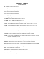

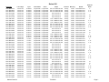

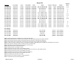
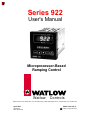
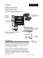

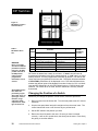
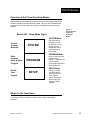


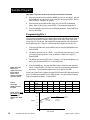
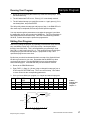
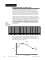
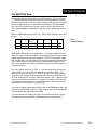
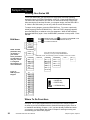


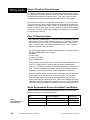
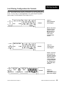
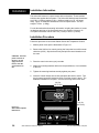

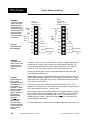

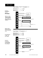
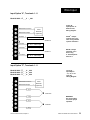


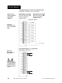
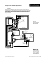

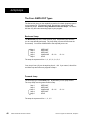
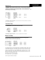
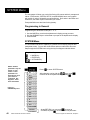
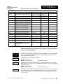

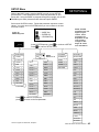
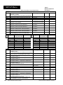
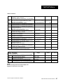
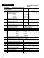


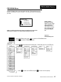
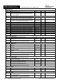
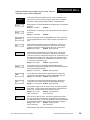
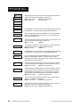
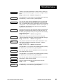
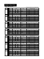
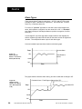
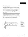
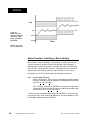

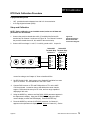
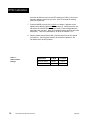
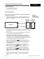


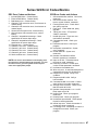
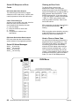
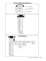


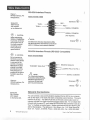

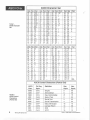
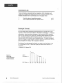
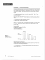

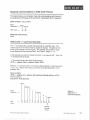
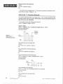
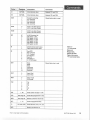
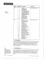
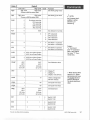

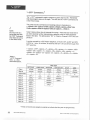
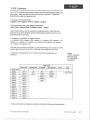
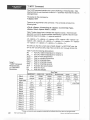


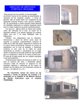


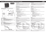
![Tester Bench [BETA] User Manual](http://vs1.manualzilla.com/store/data/005798606_1-651c3b6b51a13c0d6f27995a84bd9cc4-150x150.png)