1
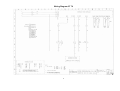
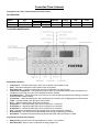
Controlled Thaw Cabinets
Designed for the safe, uniform thawing of frozen foods.
Specification
Model
CT20
CT70
Cubic Capacity
(kg)
20
70
Refrigerant
Type
Charge
R134a
230 gms
R134a
300 gms
Capillary
3m x .042
3m x .054
Electrical
Supply
230-1-50
230-1-50
Extraction
Rate
330
520
Fuse
13
13
Controller Identification
Illuminated Indicators
•
•
•
•
•
•
•
•
•
•
•
•
•
•
Compressor – LED illuminated green when the Condensing Unit output is high.
Heat – LED illuminated green when Heater output is activated.
Evaporator Fan – LED illuminated green when the Evaporator Fan output is high.
Food Probe Temperature – LED illuminated amber when the Calculated Stored Product Temperature is
outside the preset High and Low Food Temperature Alarm Settings.
Overtemperature - LED flashing red in the event of the cabinet internal temperature exceeding the preset
Overtemperature Alarm Setting.
Food Probe – LED illuminated green when temperature of the food probe is displayed on the fascia panel.
Thaw – LED illuminated green during the Thaw Phase.
Hold – LED illuminated green during the Hold Phase.
Programme 1 – LED illuminated green when Programme 1 is selected.
Programme 2 – LED illuminated green when Programme 2 is selected.
Programme 3 – LED illuminated green when Programme 3 is selected.
Run – LED above the Sleep/On Key illuminated green during programme operation.
Programming – LED above Set key illuminated green during programming procedure.
Hold Alarm – LED above the Alarm Mute key illuminated green after Hold Alarm is muted.
Key Symbols Display Fascia Panel
•
•
Sleep/on Key. Switches the controller between the ‘sleep ‘ and ‘on State.
Start /Stop Key. Starts or stops a selected controller programme.
1
•
•
•
•
Set Key. Used to enter programme sequence and acknowledge programme settings.
Time/Temp Key. Used to alter time or temperature values during programme sequence.
Defrost Key. Used in conjunction with the ‘Start /Stop Key’ to initiate a manual defrost.
Alarm Mute Key. Will mute he audible Hold Alarm permanently or the Food Temperature for a period of ten
minutes.
Controller Operation.
The controller maintains a cabinet air temperature causing controlled thawing of the stored product. Both cooling
and heating outputs will be activated to create the desired air temperature.
On start up of the cabinet, the controller enters the period Thaw Delay where only the evaporator fan motor is
running. This delay is for three minutes. During this period, either the volume of frozen product will cause the air
temperature within the cabinet to fall or the heat generated by the evaporator fan/s will cause the air temperature to
rise. After the period of thaw delay has elapsed, the controller will enter the Thaw Phase. If the temperature is
above the thaw set point plus the thaw differential, cooling will take place. If the air temperature is below the set
point minus the thaw differential, heating will occur. There will be a delay that prevents heating taking place directly
after or cooling taking place directly after heating.
When the pre-programmed Thaw Time has elapsed, the controller will enter the Hold phase. The stored product
will now remain held at an air temperature of +1°C to +4°C. Off cycle defrost will take place only during the Hold
Cycle.
Note: Even when the controller rocker switch (if fitted) is in the ‘O’ (off) position, there is still mains supply
to the controller printed circuit board. The mains supply MUST be disconnected from the cabinet before
the rear cover of the controller enclosure is removed.
Cabinet Operation.
The behaviour of the Temperature Controller is described in the form of a list of events (event/response list) with
regard to the cabinet heater components.
1. Power connected to the Cabinet – The controller is in the ‘sleep’ mode, three bars are displayed on the
fascia panel, all outputs are in a low state.
2. Sleep/On Key Depressed – The controller switches on, fascia panel indicates programmed time and internal
air temperature. Any one of the three stored programmes may be selected. Programme settings may also be
altered.
3. Start/Stop Key Depressed – The selected programme is selected.
4. Thaw Delay – The fascia panel displays Thaw, Time and Air Temperature. The evaporator fan output goes
high and the internal air temperature rises or falls depending on the volume of stored product. The displayed
Thaw Time will decrement from the programmed value.
5. Thaw Phase – If the internal air temperature is higher than the pre-set Air Temperature plus the Thaw
Differential, the Condensing Unit output goes high. When the internal air temperature rises to the pre-set Air
Temperature, the heater output will go low.
• If the internal air temperature is lower than the pre-set Air Temperature minus Thaw Differential, the heating
output will go high. When the internal air temperature rises to the pre-set Air Temperature the heater output will
go low.
• A time delay parameter ‘Cool/Heat Delay’ will prevent heating occurring directly after cooling or vice versa. The
time delay will be calculated from the time when the first output fell low.
• This Thaw Phase continues until the displayed time decrements to zero.
6. Hold Phase – The Hold alarm output goes high to indicate completion of the Thaw Phase. With the evaporator
fan output still high, the condensing unit output goes high until the cabinet internal air temperature falls to the
pre-set hold temperature. The condensing unit output then falls low until the internal air temperature rises to the
pre-set Hold Temperature plus the Hold Differential. The hold phase will continue until the programme is
stopped by the operation of the Start/stop key.
7. Time elapsed between Automatic Defrosts or Manual Defrosts (initiated during Hold Phase only).
• The evaporator fan output remains high and the condensing unit output falls low. DEF will be displayed on the
fascia panel.
• When the Defrost Termination Time has elapsed, the condensing unit output will return to a high state. The
refrigeration cycle will now re-commence with the internal air temperature again displayed on the fascia panel
Additional Features
1. Thaw Programme Extension – During the Hold Phase the Controller can be caused to re-enter the Thaw
Phase for a further thirty minutes.
2. Programme Extension can be initiated by holding down the ‘SET’ key and pressing the Time/Temp Key
2
Error Annunciation.
Should a temperature probe failure occur, the Controller will indicate the fault by flashing –
• PF1 – food temperature probe fault.
• PF2 – air temperature probe fault.
• PF4 – safety temperature probe fault.
Fault Finding – Before any checks are made to controller operation and the rear cover of the controller is
removed, power MUST BE disconnected from the cabinet.
Probe Fault
PF1 – If a food probe fault occurs the controller will continue to operate normally.
PF2 – If an air probe fault occurs the condensing unit and heater outputs will fall low.
PF4 – If a safety probe fault occurs, all control outputs will fall and the overtemperature alarm will not sound.
Probe checks are required when the controller is unable to ‘read’ one or more temperature probes.
• Check integrity of the probe connections to the controller board.
• Check resistance of the temperature probe (using an ohm meter) with the probe disconnected from the
controller printed circuit board. The temperature probes are thermistor types which change resistance when
subjected to a change in temperature. If the temperature rises the resistance should fall.
• Probe 1 – should exhibit a resistance corresponding to between +60°C to - 60°C (approximately).
• Probe 2– should exhibit a resistance corresponding to between +60°C to - 60°C (approximately).
• Probe 4 – should exhibit a resistance corresponding to between +204°C to +3°C (approximately).
See Table Below
Compressor, Heater and /or Evaporator Fan/s not working:
• Check operation of door switch. Door switches (reed switch type) should be closed – circuit with the door
closed and open – circuit with the door open (switch away from magnet).
• Check switch operation when the switch is disconnected from the controller printed circuit board by connecting
a circuit tester across the switch outputs.
Probe Temperature / Resistance Value
Probe No
Temp °C
ohms
1 and 2
+60 =
656
1 and 2
+30 =
1679
1 and 2
+20 =
2381
4
+204 =
589
4
+160 =
1465
4
+120 =
3886
Temp °C
+10 =
0 =
-10 =
+100 =
+80 =
+60 =
ohms
3448
5107
7754
6786
12552
24871
Temp °C
-20 =
-30 =
-60 =
+40 =
+20 =
+3 =
ohms
12100
19455
100181
53248
124936
280542
Alarm Functions
The Food Temperature and Hold alarms may be cancelled by operation of the Alarm Mute Key. The internal
overtemperature alarm can only be cancelled by disconnecting power from the controller or rectifying the cause of
the alarm.
1. Hold Alarm- The controller alarm output will go high on entry to the Hold Phase to indicate completion of the
Thaw Phase. The Hold Alarm will stay high for a period of the Hold Alarm Duration. Alternatively, the Hold
Alarm may be permanently muted by operation of the Alarm Mute Key.
2. Food Temperature – The controller will calculate the temperature of the stored product during the Hold Phase
through monitoring internal air temperature. Should the calculated stored temperature fall outside the
parameters High Food Temperature Alarm and Low Food Temperature Alarm, the Food Temperature LED will
illuminate amber and the alarm output will go high. Should the stored product temperature fall back within the
High and Low Temperature Alarm parameters the Food temperature LED will extinguish and the alarm output
will return to a low state. The Food Temperature Alarm (when in a high state) may be temporarily cancelled by
operation of the Alarm Mute Key. This will cause the alarm output to fall for a period of ten minutes. If after the
ten minute period, the calculated food temperature is still outside the pre-set High and Low Food Temperature
Alarm settings, the alarm output will return to a high state.
3. Internal Overtemperature Alarm – Should the internal temperature of the cabinet rise above the parameter
Overtemperature Alarm setting, possibly due to a thaw heater malfunction, the Overtemperature Alarm LED will
flash red and the alarm output will go high. Also at this point, all other outputs will fall low (condensing unit,
evaporator fans and thaw heater). The controller will remain in an Overtemperature Alarm state until power is
disconnected from the controller and the cause of the alarm is removed i.e. until the cabinet internal
temperature falls below the parameter Overtemperature Alarm setting or power is disconnected from the
controller.
3
Programme Setting and Control Parameter Adjustment.
The user can tailor the program settings to suit the particular product to be thawed. Settings can be saved in up to
three programmes, stored by the controller (P1, P2 andP3).
Control parameters alter the characteristics of the thaw control process. The controller parameters should not be
adjusted without detailed knowledge of the operation of the controller.
During the programming of either Programme settings or control parameters, if no key is pressed for a period of
two minutes, the controller will exit the particular programming mode without saving any modified settings or
parameters.
Programme Settings.
1. While the controller is switched on with the Thaw Time and Air Temperature displayed on the fascia panel, the
required stored programme can be selected. While holding the SET key, pressing the Time/Temp Key will
change the selected programme, indicated by the green LEDs P1, P” or P3.
2. To enter the programming mode the SET key must be depressed for five seconds, until the green programming
LED is illuminated. The Thaw Time minutes will flash and the minutes value may be altered using the
Time/Temp key.
3. Pressing the SET key again will cause the Thaw Time hours display to flash, which may be altered using the
Time Temp key.
4. Pressing the SET key again will cause the green Thaw LED to illuminate and the Thaw Air Temperature may
be altered using the Time/Temp key.
5. Pressing the SET key again will cause the green Hold LED to illuminate and the Hold Temperature may be
altered using the Time/Temp key.
6. Pressing the SET key again will save the programme settings and the fascia panel will flash for five seconds
(indicating storage of the programme settings). The green Programming LED will go out with the exiting from
the programming mode.
Parameter List Programme Settings
P1
P2
P3
1 Thaw Time (minutes)
0
0
0
Minutes Duration of Thaw Phase
2 Thaw Time (hours)
6
9
12
Hours Duration of Thaw Phase
3 Chill Air Temperature (°C)
+9
+9
+9
Cabinet internal air temp during Thaw Phase
4 Hold Air Temperature (°C)
+1
+1
+1
Cabinet internal air temp during Hold Phase
4
5
Control Parameters.
1. The control parameters are accessed while the controller is in the ‘sleep’ state with seven bars displayed on
the fascia panel. While holding down the SET key, pressing Sleep/On Key will cause the fascia panel to display
the control parameter number in the left hand window and the control parameter in the right hand window. The
control value may be altered (within its limits) by operation of the Time/Temp Key. Pressing the Set key causes
the display to advance to the next control parameter.
2. To exit and save the new control parameter values, the Start/Stop Key must be depressed. The controller
reverts to the ‘On’ state.
3. To exit without saving the new control parameter values, the Sleep/On Key must be depressed. The controller
reverts to the sleep state.
Control Parameter Settings
No
P = Programmable.
F = Fixed
Setting
1
P
2 (1-10)
2
P
3 (1-10)
3
P
3 (0-20)
4
P
2 (0-10)
5
P
0 (0-10)
6
P
15 (0-30)
7
P
4 (0-12)
8
P
1 (0-7)
9
P
5 (0-15)
10
P
4 (1-20)
11
P
4 (1-20)
12
P
2 (0-99)
13
P
80 (50-120)
14
F
10
15
F
2
Title - Description
Thaw Temperature Differential
Thaw Set Point + Thaw Differential = High point of Thaw operating Range
Thaw Set Point – Thaw Differential = Low point of Thaw operating range
Hold Temp Differential
Hold Set Point + Hold Temp. Differential = High point of Hold operating range
Thaw Delay (minutes)
Delay Period before the Commencement of Thaw Phase
Cool/Heat Delay (minutes)
Minimum delay period between successive operation of cooling and heating or
heating and cooling outputs
Compressor Rest Time (minutes)
Minimum time between successive compressor operations
Defrost Termination Time (minutes)
Maximum defrost time duration
Number of Defrosts per Day
Determines duration between automatic defrosts
Drain down Time (minutes)
Time period after defrost during which the condensing unit output stays low
Recovery Time
Period after Fan Delay during which High Food Temp Alarm is disabled
High Food Temperature Alarm (°C)
Value to be added to High Point of Hold Operating Range
(Hold Set point plus Hold Differential)
Low Food Temperature Alarm (°C)
Value to be subtracted from Low Point of Hold Operating Range
(Hold Set Point)
Hold Alarm Duration (minutes)
Maximum duration of Hold Alarm
Internal Overtemperature Alarm Setting (°C)
Maximum Thaw Set Point (°C)
Maximum Allowable Thaw Temperature Set Point
Minimum Thaw Set Point (°C)
Minimum allowable Thaw Temperature Set Point
6
Wiring Diagram CT 20
7
Wiring Diagram CT 70
8
Electrical Connections
•
•
•
•
•
•
Supply
Condenser
Evaporator Fans
Heaters
Alarm
Common Neutral
1 live (L1), 1 Neutral (N1), 1 Earth (E)
1 Live (C)
2 Live (F)
2 Live (D)
1 Live (AL)
5 Neutral (N)
•
•
•
•
Food Probe
Air Probe
Safety Probe
Door Switch
2 screw terminals (PRB 1)
2 Screw Terminals (PRB 2)
2 Screw Terminals (PRB 4)
2 Screw Terminals (DOORSW)
9
Evaporator and Ducting Assembly – CT 20
10
Evaporator and Fan Assembly – CT70
Evaporator and Ducting Assembly – CT70
11
Parts Lists
CT 20
Item
Description
Part Number
Evaporator
Evaporator Fan Motor
Fan Motor Blade
Heater Rod
Controller
Food Probe
Air Probe
Overtemp Probe
Door Gasket
Door Switch
Door Lock
Door Key
Compressor
Condenser
Condenser Fan Motor
Evaporator 011880 COIL
Fan Motor PO1511AEIE5781K 220 C/W Capacitor
Fan Blade 200MMX31°
Heater Rod PAK51-2 650W 230V
Microprocessor Panel 191143
T Handle Probe
Probe Air Temperature TP002K
Probe B/C MAN-101-0005 Overtemp
CT20 556X847MM BLACK
Switch Flush Contact Reed
Lock Assembly Barrel GAST 2000
Key 92235 GAST 2000
AEZ4425Y 220/50/1
Condenser 011794 C7
Fan Motor 5138 Grid Mount 5W
15462028
15870041
00-554560
15240039
15247086
00-554451
00-555124
15247510
15211807
15243607
15230366
15230364
15422012
15432007
15470032
CT 70
Item
Description
Part Number
Evaporator
Evaporator Fan Motor
Fan Motor Capacitor
Heater Rod (x 2)
Controller
Food Probe
Air Probe
Overtemp Probe
Door Gasket
Door Switch
Door Lock
Door Key
Compressor
Condenser
Condenser Fan Motor
Evaporator LACR COIL NO 10
Fan Motor RB2C-250/84 K117
Capacitor 4UF 440V 196-4753
Heater Rod LSC 32 (C) PA144-2
Microprocessor Panel 191143
T Handle Probe
Probe Air Temperature TP002K
Probe B/C MAN-101-0005 Overtemp
Gasket Made Up Full Door Black
Switch Flush Contact Reed
Lock Assembly Barrel GAST 2000
Key 92235 GAST 2000
CAE4440Y 240/50/1
Condenser 011134 NO12BCX
Fan Motor 5135 GRID MOUNT 7W
12
15463010
15470033
15490059
15843021
15247086
00-554451
00-555124
15247510
15211731
15243607
15230366
15230364
15422044
15431120
15470026