1
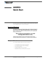
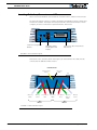
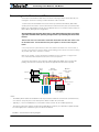
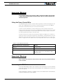
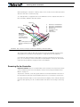
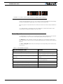
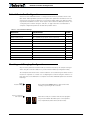
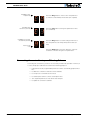
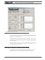
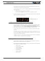
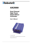
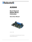
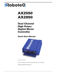
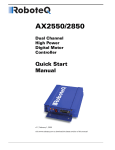
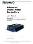
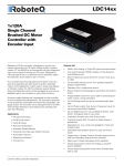
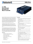
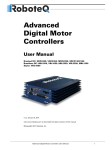
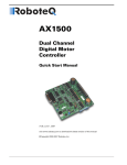
AX2550
Dual Channel
High Power
Digital Motor
Controller
Quick Start
Manual
v1.3, August 25, 2003
visit www.roboteq.com to download the latest revision of this manual
SECTION 1
AX2550
Quick Start
This section will give you the basic information needed to quickly install, setup and
run your AX2550 controller in a minimal configuration.
Important Warnings
The AX2550 is a high power electronics device. Serious damage, including fire,
may occur to the unit, motors, wiring and batteries as a result of its misuse.
Please review the User’s Manual for added precautions prior to applying full
battery or full load power.
This product is intended for use with
rechargeable batteries only.
Damage to the controller may occur if operated with a power supply.
See“Power Regeneration Considerations” on page 29 of the Users Manual.
What you will need
For a minimal installation, gather the following components
•
•
•
•
•
One AX2550 Controller and its provided cables
12V to 40V high capacity, high current battery
One or two DC motors
One R/C to DB15 connector (provided)
Miscellaneous wires, connectors, fuses and switch
AX2550 Motor Controller User’s Manual
2
AX2550 Quick Start
Locating Switches, Connectors and Wires
Take a moment to familiarize yourself with the controller’s wires, switches and connector.
The front side (shown in Figure 1) contains the buttons and display needed to operate and
monitor the controller. The 15-pin connector provides the connection to the R/C or microcomputer, as well as connections to optional switches and sensors.
Program
Set
Controller Configuration
buttons
Reset
Connector to Receiver/Controls
and sensors
Operating Status
and Program LED
Display
FIGURE 1. Front Controller Layout
At the back of the controller (shown in the figure) are located all the wires that must be
connected to the batteries and the motors.
Controller Power
Power Control
Yellow
Ground (-)
Black
(top)
Motor (+)
White
Motor (-)
Green
12 to 40V (+)
Red
Motor 1
Ground (-)
Black
12 to 40V (+)
Red
Motor(+)
Yellow or
White
Motor (-)
Green
Motor 2
FIGURE 2. Rear Controller Layout
3
AX2550 Motor Controller User’s Manual
Version 1.3. August 25, 2003
Connecting to the Batteries and Motors
Connecting to the Batteries and Motors
Connection to the batteries and motors is shown in the figure below and is done by connecting the set of wires coming out from the back of the controller.
1- Connect the two thick black wires to the minus (-) terminal of the battery that will be
used to power the motors. Connect the two thick red wires to the plus (+) terminal of the
battery. The motor battery may be of 12 to 40 Volts. There is no need to insert a switch on
these cables, although one is suggested.
Avoid extending the length of these wires as the added inductance may cause damage to the controller when operating at high currents. Try extending the motor wires
instead.
The two red wires are connected to each other inside the controller. The same is true
for the black wires. You should wire each pair together as shown in the diagram
below.
2- You may leave the yellow Power Control wire and the thin black wire unconnected, or
you may connect them to a power switch. If left floating, protect these wires from touching
any metallic part of the controller or chassis.
Refer to the chapter “Connecting Power and Motors to the Controller” on page 23 for
more information about batteries and other connection options.
3- Connect each motor to one of the two output cables pair. Make sure to respect the
polarity, otherwise the motor(s) may spin in the opposite direction than expected
Motor2
Motor
Cables
-
Battery
Power Cables
Fuse
+
Motor1
Optional
Power on/off
switch
+
Power Control
Wire
12V to 40V
Motor Battery
Controller
Notes:
-
The Battery Power cables are doubled in order to provide the maximum current to the controller.If only
one motor is used, only one set of motor power cables needs to be connected
-
Typically, 1, 2 or 3 x 12V batteries are connected in series to reach 12, 24 or 36V respectively
-
The Power Control wire may be used to turn On and Off the controller, or to provide a separate and stable 12V supply to the controller’s logic (See discussion below)
FIGURE 3. Electrical Power Wiring Diagram
AX2550 Motor Controller User’s Manual
4
AX2550 Quick Start
Important Warning
The controller includes large capacitors. When connecting the Motor Power Cables,
a spark will be generated at the connection point. This is a normal occurrence and
should be expected.
Using the Power Control Wire
The AX2550 includes a DC/DC converter that will generate a 12V internal supply from the
main +12 to +40V battery. As a result, the controller will turn On as soon as its Battery
Wires (thick red and black wires) are connected to the battery.
In order to turn On and Off the controller without the need for a bulky and expensive
switch or relay on the high current wires, the AX2550 uses a Power Control wire to enable
or disable the internal DC/DC converter. When left unconnected, the DC/DC converter is
On. When grounded, the DC/DC converter is Off.
The Power Control wire can also be used to feed a stable 12V supply to the controller so
that it will continue to operate if and when the main batteries’ voltage dips below 12V. The
table below shows the various functions of the Power Controller Wire. See “Connecting
Power” on page 23 for more details on the use and operation of the Power Control signal.
TABLE 1. Use of Power Control wire
Power Control wire connected to
Action
Floating
Controller is On
Ground
Controller is Off
Separate 12V supply
Controller is On. Controller will draw power from
the Power Control wire if main battery voltage
dips below 12V.
Important Warning
Never exceed 14V on the Power Control wire as this may cause permanent damage
to the controller
Connecting the R/C Radio
Connect the R/C adapter cables to the controller on one side and to two or three channels
on the R/C receiver on the other side. The third channel is for activating the accessory outputs and is optional.
When operating the controller in “Separate” mode, the wire labelled Ch1 controls Motor1,
and the wire labelled Ch2 controls Motor2.
5
AX2550 Motor Controller User’s Manual
Version 1.3. August 25, 2003
Powering On the Controller
When operating the controller in “Mixed” mode, Ch1 is used to set the robot’s speed and
direction, while Ch2 is used for steering.
See “R/C Operation” on page 63 of the User’s Manual for a more complete discussion on
R/C commands, calibration and other options.
Channel 3
3:
4:
8:
6:
13:
7:
14:
Channel 2
Channel 1
Channel 1 Command Pulses
Channel 2 Command Pulses
Channel 3 Command Pulses
Radio Ground
Controller Ground
+5V Radio
+5V Controller
Important:
Connect pins 6 &
13 together
to provide Ground
return for Channel 3
3
Note:
Keep 7 & 14 separate to have
the radio powered by its own
battery
45
6
Pin 1
7
13
8
14
FIGURE 4. R/C connector wiring for 3 channels and battery elimination (BEC)
This wiring assumes that the R/C radio will be powered by the AX2550 controller. Other
wiring options are described in “R/C Operation” on page 63 of the User’s Manual.
Connecting the optional channel 3 will enable you to turn on and off two accessory outputs. See “Connecting Sensors and Actuators to Input/Outputs” on page 31 and “Activating the Accessory Outputs” on page 75 of the User’s Manual.
Powering On the Controller
Important reminder: There is no On-Off switch on the controller. You must insert a switch
on the controller’s power wire as described in section“Connecting to the Batteries and
Motors” on page 11.
To power the controller, center the joystick and trims on the R/C transmitter. Then turn on
the switch that you have placed on the Battery Power wire or on the Power Control wire.
If the R/C transmitter and/or receiver is powered off, the display on the controller will alternate the letters spelling “no ctrl” to indicate that it is On but is not receiving a control signal.
AX2550 Motor Controller User’s Manual
6
AX2550 Quick Start
FIGURE 5. “no control” scroll message indicates no valid R/C signal is present
Turn the R/C transmitter On. The “no ctrl” scrolling message will disappear and the display
will show steady patterns depending on the motors’ selected direction.
Move the joystick on the transmitter to activate the motors to the desired speed and direction.
See “R/C Operation” on page 63 of the User’s Manual for a detailed description of the
many features and options available in the R/C mode.
Button Operation
The AX2550 has three buttons: Set, Program and Reset. These buttons are not needed for
normal operation, as the controller is immediately operational upon power up.
The Reset button will restart the controller. This button is recessed and you will need a
paper clip to press it. Reset is also accomplished by turning the controller’s power Off and
back On.
The Set and Program buttons have the following functions depending how and when they
are pressed:
TABLE 2. AX2550 Buttons Function
Prog and Set button status
7
Function
Press and hold Program alone during reset or power up
Enter the Programming Mode.
Press and hold Set alone during reset of power up
Enter Self-Test mode. See “Self-Test
Mode” on page 55 of the User’s Manual
Press and hold Program and Set together during reset or
power up
Reset configuration parameters to factory
default
Press Program while Programming Mode
Accept previous parameter change and
select next parameter
Press Set while in Programming mode
Change value of selected parameter
Press Program pressed alone during normal operation
No effect
Press Set alone during normal operation
No effect
Press Program and Set together during normal operation
Emergency stop
AX2550 Motor Controller User’s Manual
Version 1.3. August 25, 2003
Default Controller Configuration
Default Controller Configuration
Version 1.3 of the AX2550 software is configured with the factory defaults shown in the
table below. Although Roboteq strives to keep the same parameters and values from one
version to the next, previous and more recent versions match. Make sure that the matching manual and software versions. These may be retrieved from the Roboteq web site. See
“Configuring the Controller using the Switches” on page 119 of the User Manual for a
complete configuration parameter list and their possible values.
TABLE 3. AX2550 Default Settings
Parameter
Default Values
Input Command mode:
(0) = R/C Radio mode
Letter
I
Motor Control mode
(0) = Separate A, B, speed control, open loop
C
Amp limit
(4) = 105A
A
Acceleration
(2) = medium-slow
S
Input switch function
(3) = no action
U
Brake/Coast
(0) = brake when idle
b
Joystick Deadband
(2) = 16%
d
Exponentiation on channel 1
(0) = Linear (no exponentiation)
E
Exponentiation on channel 2
Same as E, above
F
Heat Detection
(1) = run at 50% for 30 seconds and stop
H
Left / Right Adjust
(7) = no adjustment
L
Checking and Changing Configurations
Any one of the parameters listed in Table 3, and others not listed, can easily be changed
either using the controller’s buttons or your PC with the Roboteq Configuration Utility.
The example below shows how to use the buttons to select and change the Motor Control
mode from “separate” to “mixed”. See “Configuring the Controller using the Switches” on
page 119 of the User’s Manual for a complete list of all the AX2550’s parameters and their
meanings.
Restart
Press & hold Prog
Program mode entered
after 10 seconds
Press and hold the Prog button for 10 seconds while
resetting or powering on the controller
After 10 seconds, the controller will enter the programming mode and flash alternatively the current parameter (I= Input Mode) and its value (0= R/C mode).
AX2550 Motor Controller User’s Manual
8
AX2550 Quick Start
Press Prog to select
next parameter
Press Set to select
next value for parameter
Press Prog to store change
and select next parameter
Press the Prog button to move to the next parameter
(C= Motor Control Mode) and its value (0= Separate)
Press the Set button to change the parameter’s value
(1= Combined)
Press the Prog button record the change and move to
the next parameter (A= Amps limit) and it’s value (2=
75A)
Reset controller
to exit
Press the Reset button or power off/on the control to
restart the controller using the new parameters.
Connecting the controller to your PC using Roborun
Connecting the controller to your PC is not necessary for basic R/C operation. However, it
is a very simple procedure that is useful for the following purposes:
9
•
to Read and Set the programmable parameters with a user-friendly graphical interface
•
•
•
•
•
to obtain the controller’s software revision and date
to send precise commands to the motors
to read and plot real-time current consumption value
Save captured parameters onto disk for later analysis
to update the controller’s software
AX2550 Motor Controller User’s Manual
Version 1.3. August 25, 2003
Obtaining the Controller’s Software Revision Number
FIGURE 6. Roborun Utility screen layout
To connect the controller to your PC, use the provided cable. Connect the 15-pin connector
to the controller. Connect the 9-pin connector to your PC’s available port (typically COM1).
Apply power to the controller to turn it on.
Download the Roborun software from www.roboteq.com, install it on your PC and launch
the program. The software will automatically establish communication with the controller,
retrieve the software revision number and present a series of buttons and tabs to enable
its various possibilities.
The intuitive Graphical User Interface will let you view and change any of the controller’s
parameters. The “Run” tab will present a number of buttons, dials and charts that are used
for operating and monitoring the motors.
Obtaining the Controller’s Software Revision Number
One of the unique features of the AX2550 is the ability to easily update the controller’s
operating software with new revisions downloaded from Roboteq’s web site at
www.roboteq.com. This is useful for adding features and/or improving existing ones.
AX2550 Motor Controller User’s Manual
10
AX2550 Quick Start
Each software version is identified with a unique number. Obtaining this number can be
done using the PC connection discussed previously.
It is also possible to get the controller to display the software version number by following
these simple steps
•
•
Disconnect the power from the motor batteries
Press and hold the Set button while powering or resetting the controller
The LED will display a sequence of two numerical digits and an optional letter separated by
dashes as shown in the examples below.
= Software version 1.2c
FIGURE 7. Press and hold “Set” to display version number and enter self-test
After these digits are displayed, the controller will attempt to power the motors as part of
the self test mode (see “Self-Test Mode” on page 55 of the User’s Manual for a more
detailed explanation). This is why the motor’s battery must be disconnected. After about
30 seconds, the software revision number will be displayed every 30 seconds.
You will need to reset, or power down and up, the controller to exit and resume normal
operations.
Now that you know your controller’s software version number, you will be able to see if a
new version is available for download and installation from Roboteq’s web site, and which
features have been added or improved.
Installing new software is a simple and secure procedure, fully described in “Updating the
Controller’s Software” on page 138 of the User’s Manual.
Exploring further
By following this quick-start section, you should have managed to get your controller to
operate in its basic modes within minutes of unpacking.
Each of the features mentioned thus far has numerous options which are discussed further
in the complete User’s Manual, including:
•
•
•
•
•
•
•
11
Self test mode
Emergency stop condition
Joystick calibration
Using Inputs/Outputs
Current limiting
Software updating
and much more
AX2550 Motor Controller User’s Manual
Version 1.3. August 25, 2003