1
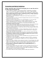
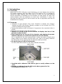
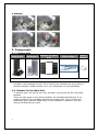
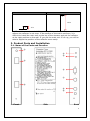
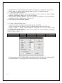
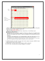
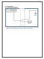
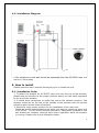
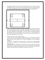
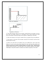
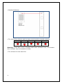
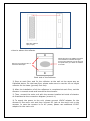
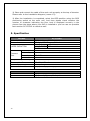
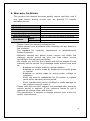
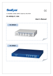
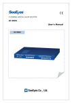
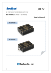
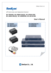
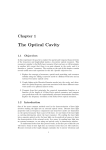
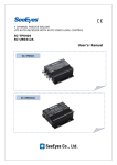
ELEVATOR FLOOR INDICATOR SC-EFI02 User's Manual SC-EFI02 Precaution and Safety Guidelines Please read this user’s manual thoroughly prior to use the unit for its easy and convenient use. Do not install the product in the following places: temperature conditions under -0°C or over 50°C; places exposed to rain, snow, or high humidity; places containing or exposed to oil and gas; places exposed to vibration and shock; places under direct sunlight or exposed to outdoor weather conditions; places exposed to radio waves (RF) or near to power lines. It may cause low performance or malfunction of the unit. Reproduction of this instruction or any part thereof without permission is strictly prohibited. Do not use and/or connect any devices inappropriate to the unit. It may cause malfunction of the unit or fire. Should you have any part of them not understandable or if you have any problem during your installation or in using it, please contact us. Please understand that the contents of this operating instruction may differ slightly due to functional improvement of a product and based on the specification chosen by the user. You can use this product easier and more conveniently if you use the function of the product only after reading this operating instruction carefully. When you need to change the character of the Elevator Floor Indicator, or to change the standard floor, or to skip some floor not used, please refer to this user’s manual or contact us. Please note that this product is working independently using its own sensor not to interrupt the elevator’s functions or make interference or damage to any facilities installed in the elevator. Please make sure that the laser beam should be off position after finish the installation of reflectors. Please do not attach any other devices to SC-EFI02. For emergency, please announce the installation status to the control room / watching center prior to the installation job. Installers should be aware of the safety equipage such as helmet prior to the installation for their own safety. At least two or more installers are required to install SC-EFI02, and please contact the elevator maintenance company prior to the installation for their any assistance. Please avoid laser radiation direct exposure to eyes. It may damage your eyes. Please use protector cable such as herical band to the sensor and the harness cable of the main unit in order to cut the cable or produce short circuit. Should use only 12VDC power adaptor. Or, it may damage the unit. Do not subject the product to physical shock or exert excessive force to operate the product. Do not use the device when any smoke or smell is produced from the unit. It may be subject to fire or electric shock. If any smoke or smell is produced, please turn off the unit and remove the power cable immediately, and contact your distributor to check the device properly. If the device does not work properly, please contact your distributor. 1 1. Introduction 1.1 Overview Using the SC-EFI02 (Elevator Level Indicator), you can display the real time lift location together with the video from CCTV camera. As it is possible to record the video together with floor level to a DVR, you can trace getting on/off movement of suspects at the elevator. As the sensor at main unit communicates with the reflectors at each floor individually, it does not intercept the data at the lift, and so there will be no argument with the lift maintenance company. 1.2 Features • Indication of the elevator floor level. Possible to display the elevator location as OSD (On Screen Display) number on the monitor for CCTV camera installed at the elevator • Tracing the getting on/off movement of suspects at the recorded video in a DVR. • Real time monitoring of the lift movement • Possible to set the angle of the camera to display the face of the persons in the elevator • Easy installation on the top of the elevator and sharing the power with the camera (no need extra power for the SC-EFI02) As it is possible to use the camera power, it does not need to install extra power cable for the sensor and the main unit. And it can easily install at the back side of the camera with the harness cable provided. • Six positioning of OSD off selectable You can select the position of the floor indicator as below. • Provided with reflectors and silicon glue to easily adhere on the wall • Possible to indicate from the 99 levels above ground to the 9 underground levels (B9 ~ 99) 2 • Example 2. Components 2-1. Components Main Units Reflectors Bracket for Main Unit Silicon Glue User’s Manual 14 pcs / 1 pc • Binding bolt for sensor bracket, iron screw and the washer ※ Installation accessories such as spring washers, screw and others are included in the package as well. If you need more reflectors for more than 15 stories buildings, please contact us or your distributor for the availability. 2-2. Bracket for the Main Unit To put the main unit on the top of an elevator, you should use the mounting bracket. There are two types of mounting brackets: the standard bracket with 3 cm height included in the package and the tall bracket with 15 cm height sold separately upon request. Depending on the installation condition, you can choose the bracket you need. 3 Standard Tall 15Cm 3Cm ※ The tall bracket is needed if the surface of the wall on which you want to adhere the reflector is not even. If the surface of the wall is not even, it is difficult to install the main unit on the top of the elevator and put the reflector at the right position on the wall. If you put the main unit 15 cm up, you will be able to adjust the position of the reflector more easily. 3. Product Parts and Installation 3-1. Name of the Parts and Function ① ④ ⑤ ② ⑥ ⑦ ③ ⑧ ⑨ Front Side Back 4 ① LASER OUT: It indicates the right position to place the reflectors on the wall. Please read the safety guidelines at page #1 prior to install the units. ②, ③ Sensors: Laser sensors ④ LASER ON/OFF BUTTON: Press this button to turn on/off the laser. Please read the precaution notes prior to use the button. ⑤ OSD Position Setting Button: You can change the position of the characters indicating the floor displayed on the screen. ⑥ RS-232C Port for the OSD Setting ⑥-1. How to set the OSD menu * Use this menu only when you should change the OSD. • First, connect the SC-EFI02 to a PC or laptop using the RS-232C port. •Then, install a serial communication program to the PC using the hiperterminal of the Windows. - Select the serial port you want to connect the communication program (COM1, COM2, COM3, ….). Baud Rate 115200 bps DATA 8 bit Parity none Stop 1 bit Flow control none • If you turn on the SC-EFI02 after connecting the unit to the PC using the RS232 serial cable, it is displayed the following menu at the window. 5 Reset Cursor Floor # Characters or numbers indicating the floor level • Select and change the characters or numbers by moving the curser using the direction keys on the computer’s keyboard. • You can use “0~9”, “A~Z”, “,”, -“. • RST: It indicates the base floor level. Select from -9 to 99 floor level. ※ What is a base floor? The SC-EFI02 has a separate sensing structure in order not to interrupt the operation of the elevator by its sensor. So, you should install the reflector for the base floor, the reflector with 19cm, to reset any possible error be produced during its operation. - Selection of the base floor: It is recommended to select as a base floor level the floor where most of the people get on/off such as the ground level or level 1. - Installation of the reflector for the base floor: Put the 19cm reflector for the base floor. The 14 pieces of normal reflector should be use for other floors. ⑦ VIDEO IN & DC 12V OUT: Connect with video output connector (BNC-M) and power input DC jack of the camera. ⑧ VIDEO OUT: Connect with coaxial cable for DVR or Monitor. ⑨ DC 12V IN: Connect with the power adaptor for camera. 6 4. Installation 4-1. Connection Diagram SC-EFI02 CAMERA ADAPTER • Connect a power adapter (12VDC/over 0.5A) to the SC-EFI02 and supply the power of the camera through the harness cable of the SC-EFI02. 7 4-2. Installation Diagram Should be separated min. 50Cm away Reflector Inside Elevator Wall the Wall • The reflectors on the wall should be separated from the SC-EFI02 max. 1m and min. 50cm away. 5. How to install Please read this user’s manual thoroughly prior to install the unit. 5-1. Installation Order ① To attach the bracket for SC-EFI02 main unit onto the top of the elevator, please stop the elevator at the proper position where you can easily approach to the top of the elevator. ② It needs three personnels to install the unit at the elevator properly. Two persons should be on the top of the outside of the elevator and one person should be place at the inside of elevator. ③ Select the most proper position for the installation of the main unit. Please be careful when selecting the place you want to install the main unit of SC-EFI02. The SC-EFI02 and any facilities or equipments installed on the wall should not mutually interrupt each other’s operation while the elevator is running. Please refer to the illustration below. 8 For example, select a least three (3) places where can be proper for the installation of the main unit and then move the elevator from the lowest level to the highest level so as to check whether there is any obstruction or not, and then choose the most easy and proper place to install the unit. It is very important to find the most appropriate place for the main unit. First of all, there should not be any mutual interruption between the SC-EFI02 and other equipments installed. Second, the operation of the sensor should be not interrupted while the elevator is moving. Third, the distance between the elevator and the wall should be over 50cm. And it is also important to find the most proper place where the main unit can be mounted with the steel mountable rack on the elevator. ④ Mount the main unit using the bracket • Mount the main unit’s bracket (designed like ㄷ) at the lower right and lower left side using the screws provided in the package. The location of the right and left of the bracket can be varied depending on the installation conditions. • Mount the “I” bracket at the lower side of the main unit, at the opposite side of the “ㄷ” bracket. The “I” bracket can be mounted or not depending on the actual field. • Put the main unit mounted at the bracket at the place selected using the steel screw. To prevent the screw not to come loose due to the vibration produced for the operation of the elevator while you install the elevator floor indicator, please use the spring washer provided with the unit. 9 Main Unit Installation Installation of Bracket ⑤ The staff working inside of the elevator should stop the elevator at every floor and the elevator should be in automatic mode. When stopping at each floor, the elevator should be stop till the reflector is adhered on the wall. ⑥ Move the elevator to the top or bottom floor to prepare fixing the reflectors. ⑦ One person on the top of the elevator should fix the reflector and the other should assist him/her. ⑧ When you start from the bottom floor, the lowest floor level, press the button #① of the main unit at the lowest floor level and the laser pointer will light the position you should fix the reflector at the wall. Then, please fix the reflector at the laser pointer indicated position as below picture. The assistant should spread the glue on the back side of the reflector between the doublesided tape to help the installer to adhere the reflector properly on the wall. 10 • Standard Reflector Standard Reflector 6(W) X 9.5(H) • The hole of the reflector and the laser point should be located as below. Good Bad Good Good Good Warning: If the laser point is located lower than reflector’s hole, the elevator floor indicator may not operate correctly. • The reflector for the base floor 11 Base floor reflector 6(W) X 19(H) • How to adhere the reflector Spread the glue in the middle of the back of the reflector as indicated the figure Put the glue sufficiently and let the glue be spread when you attach the reflector to the wall. Remove the protective film of the double-sided tape. Back side of the Reflector ⑨ Stop at each floor and fix the reflector at the wall at the same way as indicated above. For the base floor, please make sure to use the 19 cm height reflector for the base (ground) floor only. ⑩ After the installation of all the reflectors is completed at each floor, set the elevator in manual mode and immobilize the elevator. ⑪ Then, connect the main unit with the camera installed at inside of elevator as illustrated at the connection diagram (menu 4-1) ⑫ To supply the power to the unit, please connect 12VDC adaptor for the camera to the main unit and then connect DC jack at the main unit to the camera. In case the camera is for AC power, please use additional 12VDC adaptor for the main unit. 12 ⑬ Place and connect the cable of the main unit properly at the top of elevator. Please refer to the installation diagram (menu 4-2). ⑭ After the installation is completed, select the OSD position using the OSD positioning switch at the main unit. And then please check whether the number or character indicating the floor level is displayed correctly in the picture from the place where your DVR is installed or you can use our portable test monitor SC-LFC56L to check as well. 5. Specification MODEL Video In/Out Power LASER RADIATION Video Input Video Output Connect Port Power input OSD Position Temperature/Humidity Consumption Power Case Body / Weight Dimension MODEL Base Floor Other Floors 13 SC-EFI02 CVBS 1.0Vp-p, 75Ω Term. DC Jack, DC 12V, over 500mA Max Output < 5mW WAVELENGTH 650nm± 10 CLASS Ⅲ A Laser DC-F & BNC-M Harness Cable(300Cm) BNC-F DC JACK Tact Switch -10℃ ~ +50℃ / 0 ~ 80% DC 12V / 150mA Steel / 840g 37(W) X 216(H) X 75(D)mm Reflector 6(W) X 19(H) / one (1) piece provided 6(W) X 9.5(H) / 14 pieces provided 6. Warranty Certificate This product has passed thorough quality control and test, and if this gets broken during normal use, we provide 12 months warranty service. Model No. Serial No. Distributor Date you purchased Place you purchased Warranty Period Name Purchaser Address One (1) year from the date of purchase • Please • Please check this warranty indication first. contact your distributor after checking out any defect in the products. • The standard for repairing, replacement or reimbursement follows Customer. • Warranty content any defect under normal use within the warranty service period we give you free repair service according to the warranty certificate. • We charge you with the fee of parts and service despite of free warranty service period. Any breakage made without care such as: - Breakage or trouble made by natural disaster. - Breakage or trouble made by breaking the product guide or manual. - Breakage or trouble made by wrong power voltage or frequency. - When you want to reassemble for full system or replace parts within warranty service period. - When unauthorized person modified or made damage on the product trying to repair it. • Please note that we don’t support the breakage after warranty service period is expired. If the customer wants to get it repaired, we charge them with the fee. • The specification is subject to change without prior notice for quality improvement. 14 SeeEyes Co.,Ltd is the New Corporate Name of Samsung CCTV Service Co.,Ltd SeeEyes Co.,Ltd #502~506, Sunil Technopia, 440, Sangdaewon-Dong, Jungwon-Gu, Sungnam-Si, Gyeonggi-Do, Korea TEL : +82-(0)31-777-3508 FAX : +82-(0)31-777-3512 EMAIL : [email protected] http://www.sscctv.com/eng 15