1
Table of Contents
S.1 Printer Setup
S.2 Register Setup
S.3 Credit Card Setup
S.4 Kitchen Video Setup
S.5 Exchange Rate
S.6 Berg Liquor System
S.7 PDA Configuration
S.8 EnterPrize Manual
S.9 Scale Interface Manual
S.10 Intercard Setup
S.11 Mercury Gift Card Setup
Setting up Printers
BIOS
The parallel port must be set to allow bi-directional communication.
WINDOWS
Install Epson Advanced Printer Driver <ADT209E.exe> in default directory
When prompted to Select Install Modules, choose:
√
StatusAPI (THIS BOX MUST BE CHECKED)
√
The printers that are in use on the terminal where you are
installing ADT209E (Example: TM-T88III Receipt for the receipt
printer, and TM-U210B Receipt for the Kitchen Remote)
Restart the computer when prompted.
In the Windows printers folder, rename the Epson printers that the
ADT209E.exe installed according to their function (Receipt, Bar, Kitchen,
etc,), and share the ones that will be accessed by other terminals from
across the network (Kitchen, Bar, etc.). If you are upgrading the Epson
Advanced printer driver and have printers already installed, see upgrade
notes below. Delete any virtual Epson printers that were created that you
will not be connecting directly to this terminal.
Then go to the Windows Printers folder. In each local printer’s properties,
click on the Ports tab and adjust the port. For printers attached to LPT1:,
leave the port set to ESD_LPT1. For printers attached to COM ports, select
the ESD_xxx port. Example: for a Remote on COM1: you would select
ESD_COM1.
Then install all Remote printers by browsing from each terminal across the
network to the terminal where the remote printer is attached and doubleclicking on the shared printer.
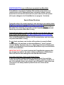
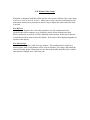
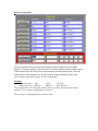
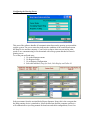
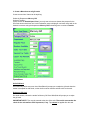
MICRO$ALE:Printer Setup Screen
Receipt Setup
Click the drop-down arrow and select Ne00: This will display a Device name
in the available printers box to the right. Keep selecting ports until the
correct device name is displayed to the right. Click Save Receipt.
Remote Setup
One at a time, type the printer name (Kitchen, Bar, etc.), Click the dropdown arrow under available port, and select Ne00: This will display a
Device name in the available printers box to the right. Keep selecting ports
until the correct device name is displayed to the right. Click Save Remote.
Note: you MUST save each remote printer individually.
PRINTER MONITOR (runs in Windows separately from Micro$ale)
Normal systems do not need any changes to be made to the
PrinterMonitor.exe program. Systems that use the receipt printer as a
remote printer and/ or systems that have a terminal hosting a remote
printer but do not wish for that terminal to print orders to its own printer
will require changes to the PrinterMonitor.exe program. See below.
Special Setup Situations
Terminals where the receipt printer is also serving as a remote printer
(Ex: Bar receipt printer is also the Bar remote printer):
In Windows, the printer MUST be named the same as the remote printer in
Micro$ale! Then click the setup button on the PrinterMonitor program and
check only the printers Micro$ale is using.
Terminal that hosts a remote printer, but the local terminal does not
print to that remote printer (Ex: Bar remote printer at Bar terminal):
In Micro$ale, you must set that printer’s port to none.
Then, in the PrinterMonitor window, click the setup button, and check only
the printers Micro$ale is using.
Do not check any boxes next to other office printers (or even the Back
Office printer), fax machines, or other miscellaneous “virtual” printers
(such as WinFax, Symantec Fax, etc.). Selecting printers and clicking save
creates a Configuration List file that tells Micro$ale to only check the status
of the selected printers.
IMPORTANT NOTE: You must shutdown the PrinterMonitor program after
any changes are made to the printer settings in Windows or Micro$ale so
that it will load the new settings the next time Micro$ale starts.
Upgrading the Epson Advanced Printer Driver:
If there are printers already installed, you should delete them and then
rename the new printers that are installed during the upgrade (as above). If
any of the deleted printers were shared, you will need to re-share them and
re-connect to the newly renamed printers from each of the remote
terminals.
S. 2
Register Setup Local and Remote Register Locations:
In Register Configuration –Tab Local Register Setup (see network shares)
Make sure the quick service system box is not check unless the system is being used as a quick
service system. Incorrect configuration can double up sales figures.
Press the network name button; this will capture the window network name for this computer.
Click the ellipse to select the number of user; the number of uses is determined by the license file
and will not accept keyboard input.
Click on the button Find Remote Data, the list box below will be populated with network share
found in the system. Click on a share name from the box the path will be inserted into the box
below, click on the appropriate path button to insert the text into path field.
Note: all paths are tested before they will be accepted
Data Path ; location for menu, discounts and employee records, the data path should always be
local, to set the path local click the Data Path Button, this will enter the correct local path.
Server Path; for quick service systems the path should be local! In a full service environment the
path should be set to a single station that will act as the server for the shared check file.
Common Path; location for time records, inventory records, frequent dinner this path should point
to single terminal in the system where configured for full or express service, the History Path (old
Backup Path) should be pointed to the same machine as the common path. Backup path location
for all sales history and archive files.
Manually Set Remote Data Location; in the field next to clear name type in the name of the
remote register, click the button manually set remote data location the name will be converted to
a standard naming convention, click on a button to the left of the appropriate path this will check
for system file before the path can be set, you cannot save an invalid system path.
How to Setup A Network Share
From the desk top double click my computer, double click the C drive, double click on program
files, right click on the Micro$ale directory and click on sharing. Follow the example above,
check the share this folder on the network and check allow network users to change my files and
click OK.
Note: the above example is from XP, 2000 user click on Share this folder and press OK
Remote Register Setup:
Click on the find remote users, double click from the list this will test for the system paths and
insert the remote register name as well as the remote register path in the correct fields, press save
you cannot save more location than the licensed number of users.
Do not pick the local machine from the list, only select remote users here.
Review saved user click the ellipse labeled remote register name this will display the list of all
remote register location, click and the information will be loaded, press delete to remove the
location.
Make sure that the number of users selected (Not Licensed) and the number of remote locations
match. A three terminal system should have 3 user selected from the local register setup page and
two remote register locations in the remote register location page.
If a register is down for service it is only necessary the set the number of user to the remaining
number of registers still in service.
Manually enter remote register location; type the name of the remote register in the remote
register name field the press the button labeled manually set remote user, this will validate the
remote path and create the correct remote path string.
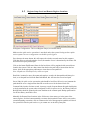
S.3 Credit Card Setup
If you are not processing credit cards through Micro$ale’s credit card interface, you must
disable credit cards on each terminal (see picture below). Check the box Disable Credit
Cards and Save.
If you are processing credit cards by phone line, you must install Datacap’s Dial E Pay
Server on the computer that the Datatran modem will be connected to. Install the Dial
E Pay Server and Epay Administrator on that terminal using the default install settings.
Start the Dial E Pay Server software once to set the default settings. You will be
prompted for the COM port number that the Datatran is connected to and the tip
percentage. Tip Percentage should be not less than 15; standard is 20.
If you are processing credit cards via a high-speed internet connection to an account with
Mercury Payment Systems, you do not need to install any additional software or
hardware.
Configure Micro$ale at each terminal:
Managers Menu – Register Setup – Register Options
If the connection is to Mercury Payment Systems, check Enable Credit Cards Online.
Do NOT check this box if you are processing credit cards through a Datatran modem.
Enable Credit Card Group allows you to set up two or more separate groups of terminals
on the same Windows network that will each work as a separate Micro$ale system, but
all groups will process credit cards via the same connection. Each group will perform
separate closing reports and store sales data separately, but credit card transactions will
be stored together for all groups. The last group to Close Out for the day must manually
activate the credit card batch routine from the Manager Menu – Credit Card Menu – Tips,
Voids, Batching – Batch Credit Cards.
Using the Group Name assignments at each terminal will organize the credit card
transactions so that each group’s reports will only show the transactions relating to that
specific group. (see Group Setup)
Hold Check Open for Tip (Full Service Option Only) will keep checks open that were
closed to credit card until a tip is applied to the transaction or Exit is pressed. The check
will indicate by color that it has been paid and is now waiting for a tip to be applied.
Enable Pre Authorization C-Cards; (Full Service Option Only) allows a user to
preauthorize a credit card for an amount before the sale is complete. (Only with open
checks and tabs)
No of Credit Card Copies: set the number of credit card charge slips that you would like
to print during credit card transactions. A credit card charge slip can also be reprinted
from the Credit Card menu. The credit card charge slip will display only the last 4
numbers of the customer’s credit card account number.
Setup a Credit Card Tender:
Register Setup -- Register Configuration
Press Tender Types button, and type in the name desired (“Credit Card” for example).
Do not separate credit card types here. The totals for each type of credit card will be
separated and itemized automatically on the reports. Press Save to save the new credit
card tender to each terminal.
Credit Card Server Setup:
ONLINE via an account with Mercury Payment Systems:
In Register Setup, Register Configuration – Credit Card / Accounts Setup tab
Primary Host Name = x1.mercurypay.com
Secondary Host Name = x2.mercurypay.com
Merchant Id Number is the account number from mercury (usually 00000000000=name)
Terminal Id = 00000
Authorize Percentage (tip percentage) should be not less that 15; standard is 20.
Click the Default Internet button, and then type the alphanumeric account number
from Mercury in the Merchant Id Number box. Save, exit to Windows, and restart
Micro$ale.
DIAL via Datatran modem using Dial ePay software interface:
For Datatran Connections, the Primary Host and Secondary Host will both be the name
of the computer the Datatran modem is attached to. The Merchant ID Number is
DialEPay and the terminal ID = 00000
Click the Default Dial button. Then click Find Network Remotes. This will create a
list of all computers on the Windows network. Click on the name of the computer
that is connected directly to the datatran modem, and then double-click in the white
box next to Primary Host Name to enter the name there. Then double-click the
white box next to Secondary Host Name to enter the same computer name there.
Save, exit to Windows, and restart Micro$ale.
DATA CAP DIAL HOST IS FOR DATA CAP DIAL HOUSE ACCOUNTS ONLY.
Once the terminals are setup and configured for credit card processing, you should
run a test transaction with every card type the store will be accepting and then
process a batch to make sure that the money is being deposited correctly.
S.4 Kitchen Video Setup
Micro$ale is integrated with Micro Plus kitchen video system. Kitchen video can be setup
as a Line by Line or Not Line by Line. Menu items can be routed to kitchen displays the
moment the menu item is pressed or it can be setup to display the entire order once total
is pressed.
Line By Line:
Requires one serial cable attached to a P.O.S terminal and com1.
On the kitchen video computer, up to 6 displays can be driven from this one cable.
When a menu item is pressed, it will be displayed on the monitor. If this item is deleted,
or modified it will be removed from the display. Each order will be displayed together in
one box of the display.
Not Line by Line:
Requires a cable for every monitor. This configuration is similar to a
kitchen printer setup. Each monitor will be setup in windows, (see setup), and routed the
same as a kitchen printer. Menu items are not sent to the display until the order is totaled
and cannot be changed once it has been sent.
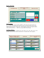
Register Name Setup:
Naming registers:
Each register must be named with REG_ followed by the register number (see
Register Name from caption above). This is the only way for the video system to know
which register the order is coming from. Kitchen displays will show the register number
at the top of the order box. Make sure you press Save when through.
Assigning a COM port:
The COM port is assigned only on the video server. The video server is the
machine where the cable connects from the P.O.S. Terminal to the video computer.
To assign the port, click on the list box from port name under Monitor Port. Select
the com port where the video server cable is connected. The data rate should be
9600,n,8,1.
Make sure you Save the settings when done.
Activate Video System:
Click on the 2 options listed above On the Fly Remote Monitors (Only) and Enable
Monitor Refresh. This must be selected on each register where the kitchen video is
desired.
Make sure you Save the settings.
Please Note: If On The Fly Remote Monitors (Only) is NOT checked you WILL NOT
be able to access the button labeled Kitchen Video Setup.
The next Item in the setup process is Video Server Setup
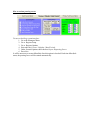
Video Server Setup:
To configure the server, press the button labeled Kitchen Video Setup. This will display a
box labeled Kitchen Video Setup (See example above). There is no need to change the
port address. Port address is the port which data is passed between the register and the
video server. Server Name: enter the name of the register where the video server is
connected. You must use the network computer name of the video server (see next page
example to get to network computer name).
Note: each register will require it own setup
Video Server:
The machine connected to the video system will need to have Start Remote Video
Server checked. (See example above in the yellow box)
Only the video server should have this box checked.
To find the network computer name, click start on the task bar.
Click Settings.
Click control panel.
Double click the icon labeled Network.
Select the tab, Identification
This will display the computer name and the work group it belongs to.
This video system will NOT work if the network computer name is not correct!
Network Setup:
When setting up the register system network, TCP/IP is the required protocol with
assigned IP address.
How to set an IP address:
Click start, click settings, click control panel, double click network. Select
TCP/IP and click properties, click the tab labeled IP Address.
Check to label Specify an IP address.
Example: Each register will use the subnet mask of 255.255.255.0
Use for an IP address 192.100.50.1 increment the last number up by 1 for each register.
Use 192.100.50.2 for register 2 and so on.
Monitor Assignments:
Once the options have been selected the monitors will be added to list of available
printers. To select a monitor click on the list box labeled available printers find the name
of the monitor and click, this will select the monitor port and monitor name. Once the
monitors have been assigned, you are now ready to assign monitors to menu items.
Note: monitor and remote printers can be used together.
Example:
Remote printer 1 Expo
Com2:
GenText
Remote printer 2 Monitor 1
Monitor 1
Rmt. Monitor 1
This configuration will send menu items to the expo printer and send menu items to
monitor 1. Use as many combinations as desired.
The next step is assigning monitors to menu items.
Assign monitors to menu items:
Select a menu item. Check the box Remote Printing is Required, this will activate the
section labeled remote printers. Select the name of each remote that this menu item will
be sent to. Make sure that no spaces are skipped. The remote printing routine searches for
each printer until it sees none or not available. Any printer assigned after that will not be
accepted.
Make sure you click Save when done.
Routing modifier to different remote printers:
Modifiers, by default, travel with the menu items. If an alternate printer is required, click
the gray button on the bottom left. A blue box Remote Printer Assignment will appear.
Modifiers can be rerouted to a different printer or even skipped.
In this example, the modifier, Fries, will not travel with the menu items assigned. Fries
will not be sent to the menu item’s 1st remote printer and will be sent to monitor 2
instead.. In the remote printer assignments, setting the remote printer to none will set the
item back to default causing the item to travel with the menu items remote printers. The
advantage in using this setup is the ability to send Hot Items to 1 location and cold items
to a different.
Example:
The menu item is Steak. You could choose soup as a modifier, the steak could be
sent to the grill and the soup could be sent to the soup station. If a salad is a modifier, it
could be sent to the salad station.
S.5 Currency Exchange Rate
Setup Part1
Manager Menu – Register Setup – Register Options
General Options (1) tab, Special Options yellow section
Put a check in the box next to “Enable Exchange Rates”
**SAVE!
Setup Part2
Exit Register Options and go to Register Configuration
Closing Report Setup/ Group Names/ Exchange Rates tab
Sales Exchange Rate section
In the Exchange Name box, type the name of the second cash tender that
you accept (ex: Pounds, Yen, Pesos, etc.)
(Remember: Micro$ale will only calculate change back in the default cash
tender, not the second cash tender)
In the Exchange Rate box, type the equivalent amount for one US dollar (or
one unit of your default cash tender if other than US dollars).
Here are a couple of simple examples:
If $1 = 100 yen, then the exchange rate is 0.01
If $2 = 1 pound, then the exchange rate is 2
**SAVE!
Setup Part3
Still in Register Configuration, go to the tab for Credit Card, Paid Outs,
Special Requests, etc. and touch the Tender Types button.
In the white box next to Credit Card Name, type the name of the
second cash tender spelled the same way as in Part2 above. Check the
box next to Exchange Tender and the box next to Cash Tender.
**SAVE!
Operations
Ring up orders like normal. On the tender screen, “CASH” always
represents the default currency. You can click the Check Total in the
bottom right-hand corner of the tender screen to toggle between the Check
Total in the default tender and the total in the Exchange currency. Enter an
amount on the number pad (with decimal) and touch the appropriate tender
in the list on the left. You can accept any combination of tenders and
currencies from the list on the left. NOTE: Change will always be
calculated in the default tender, never in the second cash currency (the
exchange tender).
S.6 Berg Liquor System Interface
The Berg device sends a PLU number to the M$ liquor server. M$ looks up the
PLU number and determines if that number is assigned to any menu item. If the PLU is a
valid number, M$ will release the pour and record the PLU.
There are 3 types of records. Open Pour (liquor has been poured with out a sale), Open
Sale (liquor that was sold through the register system but not poured), and Closed Sale
(Open pours matched with open sales).
If a drink is poured and that drink’s record is never marked closed, it will then become an
exception. All exceptions from that bartender will be printed at the end of their shift. It
will show the number of exceptions, the time, and the register name. Once the
bartender’s audit is closed, those open pours will be marked as exceptions and will no
longer be updated by sales from the register system. All exceptions for the day will be
printed on the nightly sales report.
Berg Liquor System Setup:
Requires a separate license from Micro$ale.
How to Setup Berg:
You need the list of assigned PLU numbers from the Berg Liquor System. Think of
PLU numbers as pricing levels. These numbers will be used to build PLU recipes in M$.
To build the Liquor PLU’s, go to Menu Maintenance and then Menu items and pricing.
Select or create a menu item, and press the Build Liquor PLU’s button. The liquor
system PLU list will be displayed. This is a recipe list and can hold more than one PLU,
allowing you to have more than one liquor assigned to a drink.
1. Enter the PLU number from the Berg Liquor System (provided by Berg).
2. Enter the quantity of pours required to make this drink. (This quantity must be a
whole number)
Example: For the Jack Daniels menu item, a 100 was entered under PLU number. (The
Berg system is using 100 for a premium drink). The quantity is number of pours required
to make this drink. 1 pour from a premium PLU number is required to make a Jack
Daniels Drink.
Drinks can me made with a variety of different liquor amounts. Keep in mind that the
PLU is what designates how much liquor is to be poured not the quantity field; the
quantity field determines the number of pours required to make the drink.
REMEMBER NOT TO USE FRACTIONS IN THE QUANTITY FIELD!!
Configuring the Pouring Server:
This part of the software handles all communications between the pouring system and the
register system. The server status box indicates the condition of the connection between
the Berg Device and the computer. Com Port let us know what com port and at what
speed we are communicating at. Each terminal with a Berg system attached will need a
pouring server.
To set the port and baud rates:
1. Go to the Managers menu
2. Go Register Setup
3. Go to Register Configuration
4. Select the tab label, Setup for Scale, Pole Display and Caller Id
Select port name from the section labeled liquor dispenser Setup, this is the com port that
the Berg pouring device is attached to. Select the baud rate that the computer and device
will communicate at (see Berg manual for baud rate and cable configuration). Press Save
How to activate pouring server:
To turn on the Berg system interface:
1. Go to the Managers Menu
2. Go to Register Setup
3. Go to Register Options
4. Select the tab, License / Defaults / Meal Periods
5. Under licensed Options check the box Liquor Dispensing Server
6. Press Save
It will be necessary to restart Micro$ale after this option is checked. Each time Micro$ale
starts, the pouring server will be started automatically.
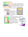
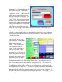
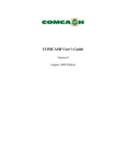
Micro$ale PDA
1.0 Introduction
Micro$ale has an optional PDA, or handheld,
configuration available. With this interface, any Windowsbased PDA with a wireless network adapter (WLAN) can be
used in conjunction with the terminal services client to afford
the server much more freedom to stay near assigned tables or
areas, without having to keep returning to the nearest
workstation to enter his/her orders. This is a guide to what
the customer would need to purchase, and how to configure
Micro$ale and Windows to get it running.
2.0 Prerequisites
In order to use the PDA option, there are a few things that have to be done.
First, there is an additional per site licensing fee. Next, and most important, is to have at
least one system in the network be running Windows 2000 or 2003 server. This should
come with at least 2 terminal services licenses. Additional licenses can be purchased if
necessary. When purchasing your PDA(s), you will need to specify 3 things: (1) Must
have Windows operating system. (2) Must have wireless network adapter (WLAN). (3)
Must have Windows terminal services client installed. After these 3 minimum
requirements have been met, another concern is that the unit(s) should be rugged enough
for every day use. In other words, an industrial-type model should seriously be
considered. It will also be necessary to have a wireless access point connected to the
network switch to provide the PDAs a way to communicate with the system running
terminal services.
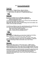
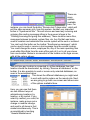
3.0 Configuration
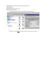
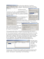
3.1 Windows set-up
After installing 2000 or 2003 Server, here is a guide on how to setup the system
for PDA use. First of all, the server should have a static IP address. This will greatly
simplify the handheld’s configuration. In order to configure the Server for this, it is
necessary to go to the network configuration options. On the desktop, simply right click
“My Network Places” and left click on “properties”. This will yield a screen similar to
the picture on the next page.
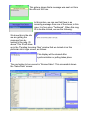
Once this is done, right click on “Local Area
Connection” and in the drop-down box, left click on
“properties”. This gives the screen in the next example:
This shows the typical
network protocols installed
with Windows. We will be working with TCP/IP. Just
scroll down until “internet protocol” is visible, then highlight
it and hit the “properties” button. This yields the screen in the
following example:
Here, it is clear that this system
is currently configured to
obtain an address
automatically. As previously
shown, this is not the recommended way to go. Instead,
click on “Use the following IP address:”. This brings up the
next screen:
The example
shows a commonly used private IP
address, but any valid address range could
be used. This will be the value entered into
the “connect to” area on the PDA.
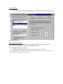
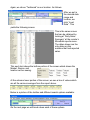
The next portion of the Windows configuration deals with setting up the connection
session. When the PDA connects, we want it to automatically sign on to the server, start
the correct program (Micro$ale), and then automatically sign off when the server logs off
the terminal. First, open terminal services on the PDA and connect to the server at the
address we have configured. At this point, it will still be necessary to put in a user ID and
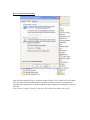
password. Once this is done, run a program on the Windows server called “terminal
services configuration”. This is found under Start/Programs/Administrative
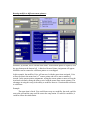
Tools/terminal services configuration. This is the screen that should come up:
Notice that it shows
a current connection
called “PDA”. This
is our office
handheld, and it
could be any name
the customer
chooses.
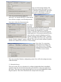
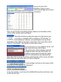
On the next page, the different options available under the connection properties will be
explained. There are, as shown, several different tabs available. The ones that will be
used are: “Environment”, “Logon Settings”, and “Client Settings”.
First, let’s look at logon settings. The
following example shows how to set up
a connection to automatically sign on the
server with “administrator” as the user
ID with its corresponding password:
(Also, do not check “always prompt for
password”, else anytime the PDA is connected the
user will have to supply a user ID and password)
Next, take a look at the Environment tab:
This shows
the actual
application, or program, that this session will
automatically start once connected. As can be seen
in the example, the checkbox for “Override
settings” is checked. This locks the PDA into this
startup application. The program path and filename
is the same that a normal workstation would use,
with the exception of the added “/PDA” extension.
And, yes, the “PDA” has to be in caps. Notice also
that the “Disable wallpaper” option is checked. This cuts down on the amount of graphics
that has to be loaded. Next, we look at “Client Settings”:
Notice that “Use connection
setting from user settings” has
been checked. Also, COM port
mapping has been checked. This
is to allow access to remote
printers.
This is the end of the Windows configuration portion. Next will be the settings necessary
within Micro$ale.
3.2 Micro$ale Set-up
This next section will cover what has to be configured within Micro$ale for handheld
operation. Once the decision has been made to go with PDA’s, it has to be turned on in
the license. Then, there are certain options that have to be set in the Handheld tab within
Register Options. This will be illustrated in the example on the next page.
This example shows the “Handheld” tab within
Register Options. At least one of these options must
be set, or when the PDA connects, the screen will
say “No handheld configuration” and log itself off.
The next example will show an actual screen after
correctly configuring the PDA, terminal services,
and Micro$ale:
This is the ID screen. Once the server puts his/her ID,
the next screen will come up:
Notice there is no “Close
Check” option. This has to be
done at a regular workstation,
or at a centralized check
closing station, if the system is
so configured. The table screen
is also a little different, as the
next illustration shows:
A table can be selected from this list, or, if the system has a
table layout configured, that could be used instead. Once a table
is selected, the display shown would be as follows:
The menu layout is obviously
reformatted to fit this screen
configuration and changes the normal
button layout into a linear format, left to
right, top to bottom. They still operate as
usual, menu items pull up attached
modifiers, and so on. Once the ticket is
completed, just hit done, and the order
will be sent to the appropriate printer.
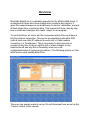
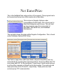
Overview
Micro$ale EnterPrize is a valuable, powerful tool for all Micro$ale users. It
is designed for those who have multiple store locations and regions. It
gives the owner/manager an invaluable way to monitor, administer, and poll
all their stores from a central location. This manual will show, step by step,
how to install and configure this useful, simple to use program.
To use EnterPrize, all stores and the corporate/central office must have a
full-time internet connection. This can be accomplished with either DSL
(with at least one static IP address for each site) or Cable modem
connection (i.e. Roadrunner). This is necessary for the home site to
connect at any time of day or night to poll or make changes to any
location(we will see why this is necessary when we cover
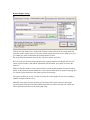
configuration/setup of regions and locations.) The following picture is of the
initial screen upon starting EnterPrize:
There are two sample markets set up. We will document how we set up the
“Tampa” market in this manual.
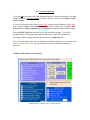
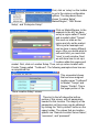
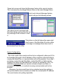
First, click on ‘setup’ on the toolbar
to go to the various configuration
options. The drop-down menu
shows “Location Setup”,
Market/Region”, “SQL Server
Setup”, and “Enterprize Setup”.
Click on Market/Region. In the
example to the left, we have
set up a region called “Florida”
and a market called “Tampa”.
We used our state as the
region and city as the market.
This is just an example and
can be done in many different
ways. After you decide what to
call each field, you must click
“save” in each window. Next,
we will show how to set up a
location within this region and
market. First, click on Location Setup. Then, set up a store location with
Florida/ Tampa called “Testboard”. The following examples show how we
accomplished this:
This screenshot shows
that we have assigned
location name “Testboard”
to Market “Tampa” and
Region “Florida”. This is
the upper portion of the
“Store Location Setup” screen.
This shot to the left shows the bottom
portion of this screen, with all parameters
needed for this location. The majority of the
parameters on this screen can be obtained
by clicking the “Set by default” button on the
upper toolbar. The values that are location
specific are “Remote Location Server Name”,
“username”, and “password”.
Our testboard machine’s IP address is the value used for the remote
location server name. In an actual situation, the remote router’s IP address
would be used. This, as well as the username and password, will be
covered in greater detail in the NetEnterPrize section of the manual. The
Location In Box, Out Box, and Main Dir paths tell the office computer where
to store databases and message files used when uploading and
downloading to and from this specific store location. The same holds true
for the Remote path names as well. These paths will be automatically
created and will correspond to the Region and Markets you create in that
setup portion.
In this picture, the directory
structure shows that the
region, Florida, is the
highest level, followed by
Tampa, then the actual
store location, “Testboard”.
The Outbox and Inbox
directories store incoming
and outgoing messages to
the remote location. The Local Main Dir path stores databases and system
files that have been downloaded from the remote. Any other location that is
setup within the Tampa market will also fall under the Florida/Tampa
subdirectories. There is also a field included for the store phone number.
This shot shows the
directory paths for the
remote machine. This
structure will be a little
different, as all subdirectories are within the
Micro$ale directory. Also,
note the Remote Location
Server Name. The IP address of the remote machine was used. This is
where you would put in the remote router’s address to connect to the FTP
server. This will be covered in more detail in the NetEnterPrize section of
this manual. This is also why the store must have a static, or permanent, IP
address. Otherwise, the store would have to be contacted each time a
connection was needed in order to obtain the current IP address.This
would make auto-polling impossible.
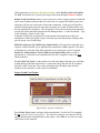
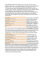
Once all of these components have been configured, it’s time to log on to
the remote site. This is accomplished by clicking the button “Log On to
Website” in the Main Menu.
This will bring up the screen shown in the following example:
This screen
shows the
different
available
locations. We
are going to
highlight
“Testboard”
and click the “Log On To Server” button to the right. This will, if we have
configured this location correctly and the location is up and running in
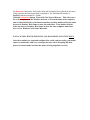
Micro$ale (with NetEnterPrize turned on), bring up the next screen:
In the example,
you can see that
we are logged
into “Testboard”.
It shows a
successful login
in the Status Log
window, and we
can now
administer this
location from our
office system.
The server name
in this case is the
IP address of this
particular system.
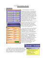
There are
many
options
available
here. For
instance, you can touch the button “Receive last 7 days sales”, which will
pull the sales summary info. from this system. Another very important
button is “Synchronize Site”. This will receive and send any incoming and
outgoing files and/or messages sitting in the queues (shown in the
“Pending Incoming/Out going files windows). These could be menu files,
messages between terminals, system files, etc. Any file that was being
used to maintain and administer the remote system will be sent or received.
You can touch the button on the toolbar “Send/receive messages”, which
can be used to send or receive a text message from the remote location.
You could change the menu, employee file, any of the main operating files
used within Micro$ale from the main office and roll it out to all your stores
from one location. Below is a screenshot of the toolbar on the login screen,
with all the options shown:
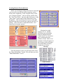
The first time any location is connected to, all the databases from that
location should be downloaded, by clicking “Receive all databases” on the
toolbar. It is also possible to send or receive only selected databases, as
seen in the examples below:
This shows the different databases you might want
to work with and/or replace on the remote site. Next,
we are going to go back one screen and show some
of the options available there.
Here, you can see that there
are two different ways of
administering locations: by
location, or by market. If you
select by market, you could, for
instance, make a menu price
change or modifier change,
and send to all stores in that
market simultaneously. This is
accomplished by touching
“General Maintenance”.
The picture on the right shows the available options
within this screen. Discount Maintenance, Sales Tax,
Customer Requests, Paid Outs, Void Reasons, and
Employee Maintenance. Each of these buttons yield a
smaller, condensed version of the same screen you
would get if you were on the actual remote machine.
Then, there is Misc. Maintenance.
This is where all message
maintenance is done. You can
change the receipt msg., daily special, and pole display
messages.
The next picture shows the menu
maintenance screen. We have all
the same options available here
as the regular Micro$ale program
on the remote. After changes are
made, the altered database is saved in pending
outgoing files and uploaded to the remote during site
synchronization or polling.
Next, we look at employee maintenance.
At left, we see the available options. You
can print an individual time card, check
overtime watch, or even close out time
records. Also notice the window identifying
that we are currently looking at Location
“Testboard”.
At left, this screen shows the
“Message Center”. The
message, as shown in the
example, is typed in on the
main window, and saved.
There is a window for
messages “from office” and “to
office”. Once a message is
typed in and saved, it goes into
pending outgoing files until
polling takes place.
This picture shows that a message was sent out from
the office at 9:40 am.
In this picture, we can see that there is an
incoming message from one of the stores; in this
case, it is from store “Testboard”. When this msg.
ID is double-clicked, we see the following:
We know this is the site
we are getting the
message from by
looking at the msg. ID
above. This ID will show
up in the “Pending Incoming Files” window that we looked at on this
particular site’s login screen, as follows:
This display will be cleared after
synchronization or polling takes place.
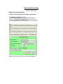
The next option to be covered is “Review Sales”. This screenshot shows
the “Sales Data” screen:
Again, we chose “Testboard” as our location. As follows:
After we put in
the desired date
range and
location, we
click “Load
Data”. This
yields the following screen:
This is the same screen
that can be obtained by
looking at “Daily Sales
Summary” at the remote’s
Micro$ale reports menu.
The dates shown are the
only dates on this
machine that had reported
sales.
This next shot shows the bottom portion of the screen which shows the
Market, Region, and
location we are seeing.
At the extreme lower portion of the screen, we see a line of values which
are all the various averages from the report above.
Below is a picture of the toolbar and different search options available:
On the next page we will break down each of these options.
Reports by Region/Market: Show Sales Mix Region/Market:
Sales Mix:
Unit Reports:
All these options allow the user to get information more specific than the
general summary screen shows.
Another option available on the main screen’s tool bar is “Purge Records”:
This allows the user to clear out old
sales data, sales mix data, or
duplicate records. Put in the date
range desired and hit the appropriate
button.
The picture at left shows the “Product Cost”
screen. Each of these items are menu items
from our remote location. If you type in the
actual cost of the item, it will show the
percentage of profit earned on the “Review
Sales” screen if the sales mix option is taken.
On the next page, we will show the Sales Data
screen after we entered in some sample
product costing on this screen.
As you can see in the
illustration, there is now a
markup percentage and a return
net amount.
Next, we get into the Auto-Polling feature. Below is an illustration of the
option on the toolbar and its pull-down:
What this will allow is either the setup of a daily time to poll
your sites, or manually poll by clicking on “Poll all sites”. In
most instances, however, you would want to set up a time,
preferably in the middle of the night, to poll sites. This is how this is done:
Click on “Time Setup”. This takes you to the next screen:
As you can see, it is very simple to set up. Just
type in the start time, and hit save.
This will force the office machine to poll all
configured sites every day at this time. All
pending outgoing and incoming files will be
sent to or received from the remote at this
time. Once this is set up, the bottom right hand side of the screen will show
that Polling will start at the time you have configured:
If auto-polling is not set up, the screen in this
area will say “Auto-polling not configured”.
In the next section, we will cover the NetEnterPrize portion and how to set
up the remote sites.
Net EnterPrize
This is the NetEnterPrize setup portion of the manual. This program has to
be licensed and turned on at the remote site in Micro$ale.
This is done in Register Options under
License/Menu/Credit Cards. Put a check next to
Start Net Enterprise and hit save. This will start
up two programs upon the next re-start of
Micro$ale; Net EnterPrize, and Database
Maintenance.
The next shot shows the setup within Register Configuration. This is found
under Database Options/SQL Setup.
The Path to Import Files (EPZ) and Path to Export Files (EPZ) come up
automatically by touching the respective buttons. We put in M$ for the FTP
user name and 9137 for the password. These have to match what was put
in at the office computer in EnterPrize for this location. The send port and
listen ports have to be 20 and 21, respectively. These ports are used
exclusively by FTP communication.
These last screens will show the Message Center at the remote location.
This is accessed by touching Software Links on the main Manager Menu.
Just touch Internal Message System,
which will give the following screen:
This shows recent messages with
their time stamp, and we can click on
any message in this window to view
it.
This picture on the left shows the upper right
hand corner of the Micro$ale ID screen when
a message or messages have been sent to
this terminal from the office.
Router Configuration
The router used at the remote end has to be configured to allow port 20 to
be forwarded through to the IP address of the computer at the store that is
running Net EnterPrize, or communication will not be possible. If you didn’t
purchase a router through Micro$ale, contact the DSL or Cable modem
supplier from whom you purchased your service for assistance. Also, it is
absolutely imperative that your service includes at least one Static, or
permanent IP address, or constant incoming communication will not be
possible.
Otherwise, the store would have to be contacted every time polling or
site synchronization was necessary to obtain the current public IP address.
This would make auto-polling impossible.
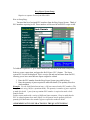
S 9.0 Scale Interface Manual
Setting Up Scale
Micro$ale interfaces with the NCI
Weightronix 6720 scale. To setup the scale
to work with Micro$ale the first thing that
needs to be done is to connect the scale to a
serial port on the computer. After the scale
is physically connected to the computer start
up Micro$ale and go to the manager’s menu.
From the manager’s menu, select the
“Register Setup” key. This will take you to
the “System Setup” menu. Once inside the
“System Setup “menu select the
“Printer/devices Setup” button, this will take
you to the “printer setup” screen. On the
bottom of the screen is the “Attached
Devices Setup” button. This button will
take you to the “Misc. Setup” screen, which
is where you will setup the scale.
In the “Misc. Setup” screen the first item
that appears is the “NCI Scale” setup. The
first field that needs to be filled is the
“Connected To” field. Click the drop down
menu on the right hand side of the field and
select the appropriate communications port for
your device. In our example the scale is
connected to “Com 1”. The other field that
needs to be filled is the “Data Rate” field.
Once again, click the drop down menu on the
right hand side of the field and select the
correct baud rate. The scale interface in
Micro$ale will be using “9600,e,7,2”. After
the baud rate is selected touch the “Save”
button to save you new settings.
If the scale has been successfully installed, then the
word “HELP” should now appear directly above the time
on the “I.D. Entry” screen. If you touch the word “Help”,
then a small popup window should appear containing
Weights and Measures” certification information.
Creating Menu to Work with Scale
Before you can begin creating menu items to work with
your new scale you will first need to setup how scaled
items will be weighed by. In the “Register Setup” menu,
go to “Register Options”. Once in register options select
the “Time Clock/ Misc.” tab at the top of the screen. In the
“Misc. Items” section look for the field marked “Scale
Weight By”. Click on the drop down arrow on the right
hand side and choose from the three options listed (lb., oz.,
and kg.). After selection is completed touch the “save”
button and exit register options.
Selecting the weight
category (lb., oz., and kg.)
effects how the scaled menu
items are displayed on the
“Order Screen” as well as how
they are displayed on the
customer receipt. Below is an
example of what will appear on
the receipt as well as the order
screen depending on which
weight type you select.
Receipt
From the manager’s menu you will next need to select
the “Menu Maintenance” button. This will take you to the
“Menu Maintenance” screen.
Order Screen
Once in “Menu
Maintenance” the first thing that you will
need to do is select the “Tare Weight
Setup” button. This will take you to the
“Tare Setup” screen. In this screen you
will be able to create the different tares
that your menu items will be using. The
first field that will need to be filled is the
“Name” field. This is where you type in
the name of your individual tares. In the
example to the right we have created a tare
called “Seafood Basket”, to be used with
our seafood items that are required to use a
scale. The second field that needs to be
filled is the “Tare Weight” field. This is where you would enter in the weight of your
tare based on the weighing option set previously (i.e. oz., lb., kg.). In our example we
have created a tare called “Seafood Basket” that weighs .25 kg. When this tare is
assigned to a menu item Micro$ale will deduct the tare weight from the price of the item.
When you have filled in both fields for your new tare touch the “Save” button and exit
“Tare Weight Setup”.
After you have created
your tares you can now create
your menu items. In the “Menu
Maintenance” screen, select the
button “Menu Items and
Pricing”. This will take to the
area where menu items are
created. In the example on the
right we have created a menu
item called “Scale Test 1”. In
this section we are only going to
discuss areas that are relevant to
scale setup. For more detailed
information on creating a menu
item please refer to the “Menu
Maintenance” section of the
Micro$ale user manual. In the field labeled “Regular Price”, you will enter in the base
price of your menu item. Our menu item has a base price of $1.49. This would be per
ounce, pound, or kilogram, depending on what you have selected in “Register Options”.
To enable the use of scale with the menu item you will need to put a check mark in the
box titled “Scale Price (Unit Cost)”. This check box lets the software know that the items
price will depend on input from the scale. After that check box is selected the finale
thing that you will need to do to setup the item for scale is select the tare for the item. To
the right of the check boxes there will be a drop down menu called “Tare weight”. If you
click the drop down arrow beside the field you will be able to choose from the different
tares that you have created. You will also have the option of selecting “Open Tare”. By
selecting “Open Tare” Micro$ale will display a pop up window to select from the tares
that you have created whenever the item is selected from the order screen. Select the
“Save” button when you are finished creating you menu item.
Misc. Information Regarding Scale Interface
- Timed Events- Timed events can be used with scaled menu items. The timed event
will effect the base price of the item.
- Manual Scale Entries- Micro$ale does not allow manual scale entries.
- Shift Levels- Shift pricing (i.e. small, medium, and large) cannot be used with scale
items.
-Item Consolidation on Receipt- The function to allow consolidation of items on receipt
will be disabled for all checks and items if the scale interface is being used.
The “Change Item” button on the order screen will only work with items
that are not set to use a scale.
The “QTY” button located on the order screen will only work with items
that are not using the scale interface.
The “repeat Item” button located on the order screen will only work with
items that are not using the scale interface.
- If an item is selected that uses the scale before anything is placed onto the scale then an
error message will be displayed stating, “Scale not Ready, Please Try again”.
Installing Intercard Components
1. Unzip and copy Cash_Connect folder to C:\
2. In Cash_Connect folder, in Package folder, run setup.exe (installs VB runtime)
3. In C:\Cash_Connect\ folder, edit Cash_Connect.ini file as follows:
[Server]
Address=192.168.0.9:3014
(assign primary transaction server IP here)
Web service=http://192.168.0.9/WS_AccountHistory/WebServiceAccountHistory.asmx?wsdl
(assign IP address of data base here)
[Connection]
Retry=5
Wait=100
[MacAddress]
Address=003A13D7M4J20
(assign MAC address of the local computer here)
4. Register dll:
Go to Start Æ Run, and type the following into the command line:
regsvr32 C:\Cash_Connect\Cash_Connect.dll
and click <Enter>
5. Install soapsdk.exe (XML-based Simple Object Access Protocol)
6. Configure M$CFG.ini file in the Micro$ale directory as follows:
[DebitCards Generic]
Return Card Sentinels..............................=On (Always On)
Max Bonus...............................................=10 ( -1 will disable, 0 will allow any amount…)
Max Courtesy...........................................=10 (…these are maximums that can be added…)
Max Ticket....................................…........=10 (…by a cashier from the order screen)
Print Sign Ticket.......................................=Yes (Yes or No to print a signature slip for purchases)
Disable Transfer........................................=No (Yes or No to disable these functions…)
Disable Consolidate..................................=No (…from being accessed by cashiers…)
Disable Card Read....................................=No (…on the order screen Debit Card menu)
Show Card Update Message................................=Yes (always on)
Print Tip Line 0 to print Line 1 not to print...........=1 (controls tip line on Sign Ticket if in use)
Account Copies ..........................................=1 (number of Sign Tickets that will print for each purchase)
Location of Debit Card File.............................=C:\Program Files\Micro$ale\ (path to shared Debit.mdb)
Text Message (Points OR Tickets)........................=Add Points (choose desired naming convention)
Debit Card Connection [Sacoa/InterCard].................=InterCard (Always InterCard {case sensitive})
Debit Card Read Track1 Track2 Both......................=Both (not in use for InterCard)
Debit Card Track Length.................................=12 (not in use for InterCard)
[InterCard]
Name of Intercard Object........................=Cash_Connect.ClsConnect (Always Cash_Connect.ClsConnect)
Use ReadWrite Debit Cards........................=No (Always No)
7. Copy a blank Debit.mdb file into the Micro$ale directory across the “Location of Debit Card File” path
as set in the M$CFG.ini file (see above).
Using Intercard Play Cards
1. Setup
Go to Manager Menu, Menu Maintenance, Menu Items and Pricing
Type a name (Play Card $)
Select the category where you want the Play Card button to reside
Select Debit Card as the department.
Enter the amount to add to the card (leave set to 0.00 if the amount will be entered at the time of
sale and then check the box for “Enable Open Price”)
Remove the “Taxable” checkmark.
Click the Debit Card Setup button if advanced options are desired. Here you can award extra
Points for a purchase, or you can award Bonus cash that can be used in the games. Bonus cash cannot be
redeemed for food, beverage, or merchandise. (Note: Courtesy and Group No are no longer used.)
Click Save, click Yes to Update All Registers, and click Yes to Assign the Menu Item to a Button.
Select the category where you assigned the item.
Touch the new item in the “Unassigned Menu Items” list, and then touch a blank button.
Set button colors if desired, and then click Save.
2. Transactions
Start a new check, and ring up the menu item (Play Card $) you created above.
You will be prompted to enter the amount to add to the Play Card. Enter an amount, using the
decimal point, and click Done. After the check is tendered, and the cashier touched the Accept button, a
window will appear prompting the cashier to swipe a Play Card to add the value to the account.
If you want to add value to multiple cards, ring up the menu item (Play Card $) once for each
card. When you close and tender that check, you will be prompted to swipe a Play Card once for each
menu item you rang up.
3. Advanced Options
From the Order Screen, click the Options button and click Debit Card.
From the Manager menu, click Software Connections Menu, and click InterCard Manager Menu.
Read Card Data allows you to see the current total Cash, Points, and Bonus on an account.
Add Points and Add Bonus allow you to add those values to the account in any desired increment.
Account History shows the total Cash, Points, and Bonus on an account in addition to listing
every transaction involving the account.
Transfer Balance allows you to transfer all of the values from one account to another (in case the
card becomes lost or damaged)
Consolidate Card allows you to combine the values from up to five Play Cards onto one of the
original cards.
Deactivate Card will mark the account as “locked” so that it cannot be used.
4. Setting up Play Card Tender
Go to manager Menu, Register Setup, Register Configuration, and click on the tab for Credit
Card, Paid Outs, Customer Requests, Job Titles, and Voids. Click the Tender Types button.
Type a name for the tender (Play Card).
Put a checkmark in the box next to Debit Card and Save.
NOTE: In Register Options, on the Modifiers / Phone Orders / General tab, make sure the Special
Option “Enable Gift Cards Local” is checked. This option must be enabled to use InterCard Play Card
functions.
Mercury Gift Card Setup
Version 6.0 and higher.
Setup in three easy steps:
1. Mercury Gift Card Settings in Register Configuration:
Port Number should always be 9100.
Set the Path to Database to the Common Path Machine.
Example : C:\Program Files\Micro$ale\ on the file server or
\\CommonPathMachineName\Micro$ale\ for other terminals.
Must Be Setup On Each Terminal including the Backoffice.
2. Setup a new tender in Register Configuration
Create a tender. Name can be anything. Check the box for Mercury Gift and Save.
The new tender only needs to be setup at one terminal. When you save it, it will update the other
terminals via the remote register location paths.
3. Create a Menu Item to sell gift cards
Create a menu item. Name can be anything.
Select the Department Mercury Gift.
Uncheck Taxable.
Check the box for Enable Open Price if you only want to have one button that prompts for the
Gift Card amount each time one is sold. Otherwise, setup multiple gift card menu items with in the
desired increments using the department Mercury Gift and making sure to uncheck Taxable.
Operations:
Sell a Gift Card
Gift Cards sell just like any menu item. Micro$ale will prompt you to swipe the gift card when the
tender is accepted for that check, so the check must be closed to add the value to the card.
Redeem a Gift Card
On tender screen, choose the tender for Mercury Gift Card. Micro$ale will prompt you to swipe
the gift card.
IMPORTANT NOTE: Tips must be entered at the time of the sale. The cashier must tender the
check for the sale amount PLUS tip amount, if any. Tips cannot be applied after the sale.