1
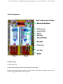
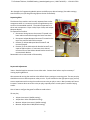
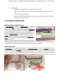
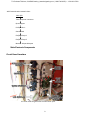
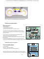
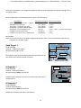
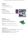
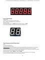
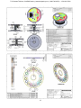
To Purchase This Item, Visit BMI Gaming | www.bmigaming.com | 1-800-746-2255 | + 1-561-391-7200 To Purchase This Item, Visit BMI Gaming | www.bmigaming.com | 1-800-746-2255 | + 1-561-391-7200 Table of Contents Manual Revision History 3 Basic Components 4 Game Setup 4 Separating Sides 5 Payout and Adjustments 5 Game Play Sequence/Behavior 6 Technical Operation 7 Wheel location and ball scoring 7 Ball Lift Operation 7 Ball Drop Operation 7 Inter Board Communications 8 Main Electronic Components 9 Circuit Board Locations 9 Electronics and Descriptions 10 Programming Options 15 Alternative Ticketing and Card Swipe System Configurations 19 Error Codes and Troubleshooting Guide 22 Mechanical Drawings 24 2 To Purchase This Item, Visit BMI Gaming | www.bmigaming.com | 1-800-746-2255 | + 1-561-391-7200 Manual Revision History Revision A-01/20/11-Release to Production 3 To Purchase This Item, Visit BMI Gaming | www.bmigaming.com | 1-800-746-2255 | + 1-561-391-7200 1-Basic Components 2-Game Setup Unloading/Assembly Carefully remove packing material and unload machine from pallet Locate power cord shipped in the cash box. Connect cord to power input on the game. Plug cord into the wall. Toggle power switch to power game on. 4 To Purchase This Item, Visit BMI Gaming | www.bmigaming.com | 1-800-746-2255 | + 1-561-391-7200 -Run through the ‘Programming Mode’ options and define your desired settings, like credits settings, sound Volumes, etc (See Programming Options Section for defaults). Separating Sides The Monster Drop machine can be easily separated into smaller components when it is necessary to pass through doorways too small for the assembled machine. The machine separates in to three main components: Player 1 side, Player 2 side, and Jackpot Marquee display. To separate the machine: 1. Disconnect Joining Harness Connectors located in the lower cabinet accessible through the lower front door. 2. Disconnect Jackpot Marquee Connector located on the top of the machine behind the marquee. 3. Remove (2) Jackpot Marquee Mount Screws and remove marquee. 4. Remove (2) of the Cabinet Attach Bracket Screws and separate cabinet halves. If minimum size is desired, remove all four of the Cabinet Attach Bracket screws and remove Attach Bracket. Reassemble in the reverse order of disassembly. Top of Machine Payout and Adjustments *Note: Standard machine assumes 1 cent ticket value. Custom wheel values may be necessary if running anything different. We recommend running the machine at the default factory settings as a starting point. The cost per play should be one coin at about a quarter value per coin. If your location has the right patron type, you may want to experiment with running the machine at two coins per play or more. Many locations will see an increase in revenue when set to two coins per play, especially where a card system is used for buying credits. Here is how to configure the game for different credit values: 25 cent play Jackpot Increment-1 (default setting) Jackpot Start Value-100 (default setting) Monster Jackpot Increment-1 (default setting) Monster Jackpot Start 1000 (default setting) 5 To Purchase This Item, Visit BMI Gaming | www.bmigaming.com | 1-800-746-2255 | + 1-561-391-7200 50 cent play Jackpot Increment-2 Jackpot Start Value-200 Monster Jackpot Increment-2 Monster Jackpot Start 2000 One Dollar Play Jackpot Increment-4 Jackpot Start Value-400 Monster Jackpot Increment-4 Monster Jackpot Start 4000 Run the game for two weeks to properly average a payout percentage before adjusting anything as the machine may show false payout spikes due to jackpot hot or dry runs over short periods. To increase the payout, increase the ‘Jackpot Increment’ setting described in the ‘Programming’ section. Each increment up will increase the payout by about 4% at $0.25 per play, 2% at $0.50 per play, or 1% at $1.00 per play. Further adjustment can be made by increasing the ‘Jackpot Start Value’, ‘Monster Jackpot Increment’, or ‘Monster Jackpot Start’ values. To decrease the payout, decrease the ‘Jackpot Start’ setting described in the ‘Programming’ section. Though not recommended unless absolutely necessary, further adjustment can be made by decreasing the ‘Jackpot Start Value’ or ‘Monster Jackpot Start’ values. 3-Game Play Sequence/Behavior I. II. III. IV. V. Power-Up Initialization Sequence a. Wheel begins spinning, displays and LED’s light up, and ball lift may run to fill the ball trough if it needs a ball or balls. Attraction Mode: a. Various lights and sounds are triggered at a programmable frequency Adding Money: a. “Coin-in” or “bill-in” sound is heard on speaker. b. When enough money is added to buy credit(s), the current credits value will be shown on the Jackpot display, and the game will enter Play-Mode Play Mode: a. Play sounds start b. Play button flashes Player Hits Button: a. Ball drops onto playfield b. Ball Lift begins to run to replenish played ball c. Ball lift stops when played balls are replenished in the ball trough 6 To Purchase This Item, Visit BMI Gaming | www.bmigaming.com | 1-800-746-2255 | + 1-561-391-7200 VI. Scoring/Payout a. Ball drops into hole on wheel or into Monster Jackpot hole b. Light and Sound celebration if Jackpot is hit or standard win sound when other value is hit c. Game pays appropriate tickets d. If player has more credits, the machine will continue on play mode, otherwise the game will go back into Attract-Mode. 4- TECHNICAL OPERATION Wheel Location and Ball Scoring The playfield wheel is driven by a stepper motor using a friction drive. There is a pin positioned explicitly in the bottom of the wheel as a home position. The pin travels through an opto sensor mounted to the playfield underneath the wheel once per wheel revolution equating the motor step count to the wheel position. There is an opto sensor pair (transmit & receive) underneath the playfield to sense when a ball has fallen through the wheel. These sensors have a short harness connecting to sensor circuit boards located on the top side of the playfield so that the sensor status can be viewed. Since the computer knows where the pin in the wheel is relative to each hole position and it knows how many motor steps from home to each hole, we know exactly which hole the ball fell through allowing a payout accurately corresponding to the hole position. Ball Lift Operation A stepper motor is connected to the ball lift via a urethane round belt. There is an opto pair (transmitter & receiver) located in the ball trough used to sense the presence or absence of a third staged ball. As long as there are three balls in the ball trough interrupting the opto, the ball lift will stay at rest. At any time, if there is no ball interrupting the opto the ball lift will run and continue to run until three balls are staged in the trough and the opto is blocked. The ball lift will run after each ball is dropped replenishing the third ball in the trough. 7 To Purchase This Item, Visit BMI Gaming | www.bmigaming.com | 1-800-746-2255 | + 1-561-391-7200 Ball Drop Operation There is a solenoid located above the ball trough. The solenoid plunger directly contacts the first staged ball containing it in the trough. When credits are available and the play button is pressed, the solenoid is activated pulling the plunger up and away from the ball allowing it to roll out of the trough, down the ball chute, and into play on the wheel. The plunger returns just after the first ball is cleared in time to block the next staged ball and keep it from dropping until the play button is pressed again. Inter-Board Communication The Circuit Boards communicate with each other using a 485 differential wire-pair network, using the SNAP software protocol layer. - On this machine, this wire pair has colors Blue and Gray. - The Main CPU Board acts as the master, initiating commands and receiving responses from the slave boards. - Like-boards differentiate from each other by means of an ID-Switch setting. See the following pages to find each board’s ID-Switch location and setting. - The following board(s) are NOT connected to the 485 network: > The Power distribution board. > The Opto Sensors. -Note that the 485 network wire-pair chain jumps from board to board: > In some places the chaining is done by double-crimps at the connector (these are usually 2-pin connectors) >In other places, PCB traces on the board itself carry the chain from a pair of connector pins to the next (usually a four-pin connector); thus, disconnecting such a board’s 485 might actually disconnect the rest of the 485 chain. Keep this in mind when troubleshooting or replacing parts. 8 To Purchase This Item, Visit BMI Gaming | www.bmigaming.com | 1-800-746-2255 | + 1-561-391-7200 -485 Communication network chain: Main CPU Ticket dispenser connector Quad Stepper IO-Expander-1 Sound Board Playfield Player 1 Playfield Player 2 Monster Jackpot Marquee Main Electronic Components Circuit Board Locations This view inside the game with the lower door open. 9 To Purchase This Item, Visit BMI Gaming | www.bmigaming.com | 1-800-746-2255 | + 1-561-391-7200 This is a view of the back of the Marquee removed from game. Electronics and Descriptions Main CPU Board Part# PCB10002 Location: Inside lower cabinet ID-Switch setting: None, this is the master board. J2: LOGIC OUTPUTS This board is the main controller of the game. It decides all the game actions and commands the other boards to act according to the game scheme. J3: LOGIC INPUTS J1: DC POWER, 5V U4: Game Program Flash ROM Communication to the other boards is performed via a 485 differential wire-pair (Gray and blue wires). 485 Communication The ‘Programming Mode’ game-settings information is also saved on this board. The actual Game code resides on the removable Flash-Rom chip (U4); this chip can be replaced/upgraded if necessary (Using a PLCC32 extractor tool). LCD Display Control Main ROM program Version Updates: OUTPUTS Power Distribution Board Part# PCB17001 Location: : Inside lower cabinet ID-Switch setting: None, board has no computer. Distributes DC power from the power-supply to the different devices, through a Poly-Switch (thermal, resettable fuse) for each voltage circuit. 10 S wi tc h 3S wi tc h 2 S wi tc h 1 Swit ch Outp uts Circuit overload LEDs Poly Switch Fuses (1A) Input Voltage LEDs (must be On) INPUTS To Purchase This Item, Visit BMI Gaming | www.bmigaming.com | 1-800-746-2255 | + 1-561-391-7200 Not that for convenience, the ‘Programming Options’ Buttons are also located on this board, although they’re not power related. Power is distributed in the following manner (worst case estimations): Board/Device Estimated consumption -Quad Stepper Board (main CPU) + 4 Motors (24V, 3A) -Sound Board (on Top Panel) (12V, 140mA) -IO-Expander 1 (+Playfield Top Lights) (12V, 500mA) -IO-Expander 2 (+Playfield Bottom Lights) (12V, 500mA) -IO-Expander 3 (+Coin/Bill,light-strips) (12V, 4A) - x3 Opto sensors (Trap Door Assy) ( 5V, 60mA) - x2 Opto sensors (Claw Assy) + Credits Display ( 5V, 160mA) Fuse circuit (see board) (*24A*) (*12B*) (*12C*) (*12C*) (*12A* + *12D*) [3A peak: Bill Acceptor] (*5A*) (*5B*) Related Note: Note: There are 2 AC fuses on the Power supply group (10Amp, 250 V). They’re found inside of the ICE-C13 receptacle on the power supply. Quad Stepper 1 Part# PCB11006 Location: : Inside lower cabinet ID-Switch setting: 00 (off-off) J1: MOTOR DRIVER OUTPUTS ID Switch J2: LOGIC INPUTS This Stepper-motor controller board handles the movements of the two wheel motors and the two ball lift motors. IO-Expander 1 J3: Power, 12V 485 Communication J3: OUTPUTS, Open Collector Part# PCB14008 Location: : Inside lower cabinet ID-Switch setting: 0100 (off-on-off-off) J1: LOGIC INPUTS ID-Switch Handles all LED’s located in the two main cabinet areas (all except marquee LED’s). 485 Communication J2: Power, 12V IO-Expander 2 Part# PCB14008 Location: Inside Marquee ID-Switch setting: 0000 (off-off-off-off) Handles the left half of the LED’s in the Marquee. 11 To Purchase This Item, Visit BMI Gaming | www.bmigaming.com | 1-800-746-2255 | + 1-561-391-7200 IO-Expander 3 Part# PCB14008 Location: Inside Marquee ID-Switch setting: 1000 (on-off-off-off) Handles the right half of the LED’s in the Marquee. Sound Board SD-CARD BAY Part# PCB041 Location: : Inside lower cabinet ID-Switch setting: 0000 (off-off-off-off) 485 Communication RCA AUDIO OUTPUT Handles background and event sounds. Sound files are stored on the plug-in SD-card memory board. Power, 12V RCA AUDIO OUTPUT Opto Sensors Part# PCB009 [Right Angle Connector] Location: Underneath playfield wheel Qty: x4 ID-Switch setting: None, it has no 485 communication. It detects the wheel home position and the ball through the wheel. Notes: This sensor board has a Green LED that lights up when the IR beam is interrupted. The two ball-sense signals go to the Quad stepper Board Inputs, J2 connector Large 5-Digit Display Part# PCB033 Location: (2) Inside play area mounted to back panels & (1) Inside Monster Jackpot display assembly Qty: 3 (1 for Jackpots Player 1 and Player 2 & 1 for Monster Jackpot) ID-Switch settings: Jackpot/Credits Display Player 1: 000000 Jackpot/Credits Display Player 2: 010000 Monster Jackpot Display: 001000 The ID-Switch is located on the back of the Display and is labeled as “S1”. 12 ID-Switch To Purchase This Item, Visit BMI Gaming | www.bmigaming.com | 1-800-746-2255 | + 1-561-391-7200 Large 2-Digit Display Part# PCB034 Location: (2) Inside play area mounted to back Qty:2 (1 each for Bonus Balls Player 1 and Player 2) ID-Switch settings: Bonus Balls Display Player 1: 100000 Bonus Balls Display Player 2: 110000 The ID-Switch is located on the back of the Display and is labeled as “S1”. Ticket Dispensers (Intelli-Triple Series) Part# Location: Ticket Side-Doors Qty: x2 (1 for each player side) IMPORTANT NOTE: These ticket dispensers for Monster Drop DO NOT use the standard “Run” and “Notch” lines to communicate with the main CPU Board; instead, they do it through the 485 comm. network. Because of this, you must be sure these devices have code version TDT 7 or higher (see sticker on PC-Board). They also need to have the proper ID switch settings, as follows. ID-Switch settings: Player 1: 000000 Player2: 100000 The Circuit-board and ID-Switch within are part of the Ticket Dispenser device, on the underside. For more information, see Benchmark’s Ticket Dispenser manual. 13 To Purchase This Item, Visit BMI Gaming | www.bmigaming.com | 1-800-746-2255 | + 1-561-391-7200 485 Communication ID-Switch Opto Single Receiver Board (Remote Receiver) Part #: PCB044 Location: Playfield top rear Qty: 2 (1 for each player side) This sensor board connects to a remote sensor. It senses the balls falling through the wheel and playfield. This sensor board has an Opto Receiver connected to it (shown below). Opto Receiver Part # 115HNS014 Location: Playfield underside rear Qty: 2 (1 for each player side) This sensor connects to the ‘pigtail’ on the Opto Single Receiver Board shown above. The sensor device on this assembly is opaque black in color. 14 To Purchase This Item, Visit BMI Gaming | www.bmigaming.com | 1-800-746-2255 | + 1-561-391-7200 Opto Transmitter Part # 115HNS015 Location: Playfield underside rear Qty: 2 (1 for each player side) This transmitter connects directly to the main harness. Note the physical difference between this assembly and the Opto Receiver is that this assembly has a resistor in series with the wire (hidden by shrink tubing) and the color of the device is translucent gray/blue while the receiver device is opaque black. Opto Single Receiver Board (Onboard Receiver) Part #: PCB021 Location: Ball Trough Qty: 2 (1 for each player side) This board mounts to the ball trough. It senses the third staged ball in the ball trough. Opto Single Transmitter Board (Onboard Transmitter) Part #: PCB020 Location: Ball Trough Qty: 2 (1 for each player side) This board mounts to the ball trough. It senses the third staged ball in the ball trough. 4- PROGRAMMING OPTIONS Programming the Monster Drop Game Entering Programming Mode To enter program mode, press the Center Button located on the Power Distribution Board, located inside the left door on the left side of the cabinet. “MONSTER DROP V.X.X – PROGRAM MODE” will appear on the LCD Display located inside the cabinet next to the Power Distribution Board. If there are tickets owed that have not been paid for either Game 1 or Game 2, then they will be displayed at this time with the option to clear them. To clear the tickets, depress the 15 To Purchase This Item, Visit BMI Gaming | www.bmigaming.com | 1-800-746-2255 | + 1-561-391-7200 Center Button again. If you wish to proceed without clearing the tickets, then depress either the Front or Back Button. If there are no tickets to be cleared or you have opted not to clear them, then “ENTER PROGRAM MODE?” will be displayed. Depressing the Center Button again will enter the Program Mode. Depressing either the Front or Back Button will revert the game back to Run Mode. If Programming Mode is selected, then “ENTER PASSCODE” will be displayed with the first digit highlighted with a flashing cursor. “ENTER PASSCODE” To be able to change programming parameters or reset the counters, a 4-digit passcode must be entered. The default passcode is 0000. To enter the passcode, depress the Center Button to change the digit from 0 to 9, then press the Front Button to move to the next digit. If you have moved to a new digit and wish to move back to a previous digit, depress the Back Button. After all digits have been entered correctly and the last digit is highlighted, depressing the Front Button will display the Programming Main Menu. General Programming Procedure Once a valid passcode has been entered and the Main Menu is displayed, the Front/Back Buttons scroll Forward/Backward through the programming options. If you wish to change an option, depressing the Center Button enters the highlighted option. The current setting for that option is then displayed. Once an option is entered, the Front/Back Buttons Increase/Decrease the option value, and depressing the Center Button saves the new value and exits back to the Main Menu. If the Front/Back Button is held and depressed when changing an option, the value will continue to Increase/Decrease. Description of Programming Options 1 CHANGE PASSCODE Entering a new passcode is accomplished in the same way as entering the passcode, as previously explained. IMPORTANT!!! ONCE THE PASSCODE IS CHANGED, THE DEFAULT OF 0000 WILL NO LONGER WORK! BE SURE TO SAVE THE PASSCODE IN A SAFE PLACE! 2 SET CONTRAST This option sets the contrast for the LCD Display. Depress and hold either the Front or Back Buttons to Increase/Decrease the contrast. Depressing the Center Button returns to the Main Menu. 3 PLAY VOLUME This option sets the speaker volume during game play. When this option is entered, the game’s background music will play continuously. Depressing the Front/Back Buttons will Increase/Decrease the volume. Depressing the Center Button returns to the Main Menu. 16 To Purchase This Item, Visit BMI Gaming | www.bmigaming.com | 1-800-746-2255 | + 1-561-391-7200 4 ATTRACT VOLUME This option sets the speaker volume during Attraction Mode. When this option is entered, the game’s background music will play continuously. Depressing the Front/Back Buttons will Increase/Decrease the volume. Depressing the Center Button returns to the Main Menu. 5 JACKPOT VOLUME This option sets the speaker volume during a Jackpot Event. When this option is entered, the game’s background music will play continuously. Depressing the Front/Back Buttons will Increase/Decrease the volume. Depressing the Center Button returns to the Main Menu. 6 ATTRA. FREQUENCY This option sets the frequency at which the attraction mode occurs. The settings are from OFF to every 30 minutes, in 1-minute increments. Depressing the Front/Back Buttons will Increase/Decrease the setting. Depressing the Center Button returns to the Main Menu. 7 GAME PRICE This option sets the number of coins required for a credit. The settings are from 1 to 8 coins per credit. Depressing the Front/Back Buttons will Increase/Decrease the setting. Depressing the Center Button returns to the Main Menu. 8 WHEEL TYPE This selects one of the existing payout options. PLEASE NOTE: Changing this from STANDARD requires a new wheel decal! Depressing the Front/Back Buttons will change the setting. Depressing the Center Button returns to the Main Menu. 9 WHEEL SPEED This changes the wheel speed from 0 (slowest) to 4 (fastest). Depressing the Front/Back Buttons will change the setting. Depressing the Center Button returns to the Main Menu. 10 JACKPOT INCREMENT Every time a credit is added to the game, the jackpot value is incremented by this amount. The setting is from an increment of 1 to 50. Depressing the Front/Back Buttons will change the setting. Depressing the Center Button returns to the Main Menu. 11 JACKPOT START VAL After a Jackpot is won, this is the new starting jackpot value. The values are from 50 to 999 in increments of 5. Depressing the Front/Back Buttons will change the setting. Depressing the Center Button returns to the Main Menu. 12 JACKPOT MAX VAL. This sets the maximum allowable Jackpot Value. The values are from 50 to 999 in increments of 5. Depressing the Front/Back Buttons will change the setting. Depressing the Center Button returns to the Main Menu. 13 JACKPOT TYPE 17 To Purchase This Item, Visit BMI Gaming | www.bmigaming.com | 1-800-746-2255 | + 1-561-391-7200 The two types of Jackpots are SEPARATE and COMBINED. If the setting is SEPARATE, then the jackpot for each game operates independently from the other. If the setting is COMBINED, then both Game 1 and Game 2 Jackpots will increment if a credit is added to either game, and both jackpots will be reset if either Game wins a jackpot. Depressing the Front/Back Buttons will change the setting. Depressing the Center Button returns to the Main Menu. 14 MONSTER JP INC. Every time a credit is added to either game, the Monster Jackpot value is incremented by this amount. The setting is from an increment of 1 to 50. Depressing the Front/Back Buttons will change the setting. Depressing the Center Button returns to the Main Menu. 15 MONSTER JP START After a Monster Jackpot is won, this is the new starting jackpot value. The values are from 500 to 99999 in increments of 50. Depressing the Front/Back Buttons will change the setting. Depressing the Center Button returns to the Main Menu. 16 MONSTER JP MAX This sets the maximum allowable Monster Jackpot Value. The values are from 500 to 99999 in increments of 50. Depressing the Front/Back Buttons will change the setting. Depressing the Center Button returns to the Main Menu. 17 DISPLAY TICKETS If this option is ON, then the tickets owed are displayed on the jackpot display, and the display is updated as the tickets are dispensed. If there are no tickets owed, then the Jackpot Value is displayed. Depressing the Front/Back Buttons will change the setting. Depressing the Center Button returns to the Main Menu. 18 MERCY TICKET The setting for this option are from OFF to 5 tickets. If the setting is OFF, then no tickets are dispensed if the ADD BONUS hole is hit. Depressing the Front/Back Buttons will change the setting. Depressing the Center Button returns to the Main Menu. 19 RESET TOTAL COINS The TOTAL COINS IN counter can be reset here. Depressing the Front or Back Button will reset the count to 0. Depressing the Center Button returns to the Main Menu. 20 RESET TOTAL TKTS The TOTAL TICKETS OUT counter can be reset here. Depressing the Front or Back Button will reset the count to 0. Depressing the Center Button returns to the Main Menu. X LEAVE PROGRAM MODE Depressing the Center Button returns to Run Mode 18 To Purchase This Item, Visit BMI Gaming | www.bmigaming.com | 1-800-746-2255 | + 1-561-391-7200 DEFAULT SETTINGS PASSCODE PLAY MODE VOLUME ATTRACTION MODE VOLUME JACKPOT MODE VOLUME ATTRACTION FREQUENCY COINS PER CREDIT WHEEL TYPE WHEEL SPEED JACKPOT INCREMENT JACKPOT START VALUE JACKPOT MAX VALUE JACKPOT TYPE MONSTER JACKPOT INC. MONSTER JACKPOT START MONSTER JACKPOT MAX DISPLAY TICKETS OWED MERCY TICKET 0000 20 42 MAX 5 Minutes 1 Coin STANDARD 4 1 Point 100 999 SEPARATE 1 1000 99999 ON OFF 6- ALTERNATIVE TICKETING AND CARD-SWIPE SYSTEM CONFIGURATIONS There are a few alternative configurations regarding Ticket Dispensers, Card Swipe systems and Electronic Tickets (e-tickets) that are possible to setup, depending on your location. These are described in a general fashion as follows. CONFIGURATION 1 NON-BENCHMARK GAMES TICKET DISPENSERS (DELTRONICS, etc): (USES BENCHMARK GAMES’ EMULATOR BOARD AS INTERFACE) The Monster Drop machine communicates with the Benchmark Games Ticket dispensers (Intelli-Triple) by means of a serial protocol over a 485 wire-pair physical path (gray and blue wire pair). If you want to run your system with other manufacturer’s Ticket Dispensers, you need to install one of our Ticket Emulator/Interface Boards to translate the communication coming from the 485 wire network into to the standard “Run” and “Notch” signals used by each of your own Ticket Dispensers. If not already present on the machine, the Emulator/Interface board for each of the 2 stations comes as a complete kit with the harnessing adaptor necessary for installation, (Kit part #105-KIT-005). 19 To Purchase This Item, Visit BMI Gaming | www.bmigaming.com | 1-800-746-2255 | + 1-561-391-7200 Attach the bracket to the board. Then connect the Emulator bracket harness to the game using the 8 pin microfit connector located above the power distribution board. Finally, set the Dip-Switch Network ID on each of the interface boards in the same binary fashion as in the large 5-digit displays or the original Intelli-Triples, as follows: Station 1: off,off,off,off Station 2: on,off,off,off CONFIGURATION 2 NORMAL CARD SWIPE SET-UP, 1 SWIPE GIVES 1 CREDIT: (THIS IS INDEPENDENT OF TICKET DISPENSER BRAND INSTALLED). The card swipe system needs to access the “Credits” signal line to the main CPU board, In order to trigger game-play. In some installations, the card swipe system is also used for basic accounting purposes, having the device count the “Notch” signal pulses produced by the Ticket Dispenser as it awards tickets. In that case you also need to tap into this “Notch” line. These two lines are available on pins at the door-hinge connector on each of the 2 player positions. Wires need to be run from the card swipe system to the corresponding mating connector on the door side. (The complete pin-outs and wire colors for each connector are listed on page 28) Station 1: Credits, pin 5 (Gray/yellow) Station 2: Credits, pin 5 (Gray/yellow) Make sure to configure your card-swipe system to provide 1-pulse only for each swipe, with the following constraints: -Minimum pulse duration: 40mS -Minimum dead-time before next pulse: 40mS Also make sure the Monster Drop Programming-Mode option “Coins per Credit” is set to 1. 20 To Purchase This Item, Visit BMI Gaming | www.bmigaming.com | 1-800-746-2255 | + 1-561-391-7200 DOOR-HINGE CONNECTOR PIN-OUTS: CONFIGURATION 3 CARD SWIPE SYSTEMS, ELECTRONIC-TICKET SCHEME: (NO TICKET DISPENSER INSTALLED) (USES BENCHMARK GAMES’ EMULATOR BOARD AS INTERFACE) In most card swipe systems running E-ticket configurations (i.e. Sacoa, etc), the device requires to be fed the standard Ticket “Run” signal in order for it to log the tickets being paid to the player. As it logs, the card swipe system will put out the standard “Notch” signal pulse for each ticket awarded, in order to behave and be compatible as a regular Ticket Dispenser. As explained for Configuration 1, the Monster Drop machine runs tickets via a 485 network, thus the ticket emulator board is needed for this setup as well, in order to produce the “RUN” signal required by the cardswipe. Note that the Ticket emulator board also Does require to see the “Notch” signal coming back for it to know that the customer is getting paid; otherwise it will report an “Out of Tickets” condition to the main CPU and the game will throw an E-3 Error. 21 To Purchase This Item, Visit BMI Gaming | www.bmigaming.com | 1-800-746-2255 | + 1-561-391-7200 CARD SWIPE SYSTEM E-TICKETS CONFIGURATION MODE Ticket Emulator board 4 power & 485 Comm. 1 1 TICKET “NOTCH” SIGNAL 2 TICKET “RUN” SIGNAL 7- ERROR CODES AND TROUBLESHOOTING GUIDE ERROR CODES, QUICK SUMMARY Shown on the corresponding player 5-Digit Display overhead. Note: Errors are more clearly spelled out on the LCD display on the Control Panel. ERROR CODES The following error codes are displayed on the Jackpot Display for each game if an error occurs. In addition a description of the errors will be displayed on the LCD display inside the left cabinet. E-1: HOME ZERO ERROR This error occurs when the Wheel Home Sensor is continually grounded, indicating a ground in the harness or a defective Wheel Home Sensor. E-2: HOME MAX ERROR This error occurs when the Wheel Home Sensor never indicates that the home position on the wheel has been reached within a specified interval. This indicates either a break in the harness, a defective sensor, that the wheel is slipping excessively or not turning, or that the pin on the bottom of the wheel is not passing through the Sensor. 22 To Purchase This Item, Visit BMI Gaming | www.bmigaming.com | 1-800-746-2255 | + 1-561-391-7200 E-3: TICKET ERROR This error occurs when the ticket dispenser is either jammed or out of tickets. E-4: TICKET DISPENSER COMM. ERROR This error occurs when communications cannot be established with the ticket dispenser. Troubleshooting Guide Symptom-Description of Proper Operation Possible Causes-Action Balls Don’t drop when ‘Drop Ball’ button is Switch Problem pressed, but Light in button is flashing and Switch in ‘Drop Ball’ switch housing is credits are availableloose-secure switch in housing When button is pressed, ground is switched to Solenoid problem the ‘Drop Ball’ input on the Main CPU. The CPU Solenoid is stuck or not working-Fix then switches the output for the solenoid to binding plunger or replace solenoid ground activating the solenoid. When the 12V power or ground to solenoid is solenoid activates, the plunger is pulled up and not working or not connected-fix out of the way of the ball. voltage problem in harness, power supply, or power distribution board Ball Lift doesn’t run and ball trough is emptyMain CPU sees a low on the input. Ball lift should run when there are less than Check that nothing is blocking the ball three balls in the ball trough. The third ball trough opto sensor-clear obstruction blocks the trough opto which switches the Output from ball trough opto receiver corresponding input on the Main CPU to is shorted-replace opto receiver ground. When the input is grounded, the CPU CPU input for ball trough opto receiver assumes there are three balls staged in the is bad-Replace Main CPU trough. Output wire between opto receiver and CPU is shorted in harness-find short Playfield Wheel starts and stops, game does Friction drive problem not score accurately or game just does not Check motor friction wheel contact on score accuratelywheel-fix any obstruction keeping Playfield wheel should run at a constant speed spring from pulling motor to wheel and the home opto pin located in the bottom of Wheel home sensor problem the wheel should pass through the home opto Wheel home pin is missing or not once per revolution. When the motor turns passing through home opto-replace or more times than it should between home opto adjust pin height in wheel triggers, the controller assumes the wheel may Wheel home opto sensor is not be stuck and slows the wheel down and tries to working-replace opto or find open restart over and over. power or signal open in harness Ball Lift runs continuously and no balls are in Ball lift ramp problem ball trough or on ball lift Balls stuck in ball lift ramp-Clear any obstructions or ball hang ups in lower ramp in lower cabinet Balls worn small or no longer round Replace balls 23 To Purchase This Item, Visit BMI Gaming | www.bmigaming.com | 1-800-746-2255 | + 1-561-391-7200 Mechanical Drawings-Visit www.benchmarkgames.com for complete drawing set. 24 To Purchase This Item, Visit BMI Gaming | www.bmigaming.com | 1-800-746-2255 | + 1-561-391-7200 25 To Purchase This Item, Visit BMI Gaming | www.bmigaming.com | 1-800-746-2255 | + 1-561-391-7200 26 To Purchase This Item, Visit BMI Gaming | www.bmigaming.com | 1-800-746-2255 | + 1-561-391-7200 27 To Purchase This Item, Visit BMI Gaming | www.bmigaming.com | 1-800-746-2255 | + 1-561-391-7200 28