1
HomePlug AV 200Mbps 4-Port Wireless-N Router
User Manual
2008 Copyright. All rights reserved. Version 1.1
No part of this document may be reproduced, republished, or retransmitted in any form or by any means whatsoever, whether electronically or
mechanically, including, but not limited to, by way of photocopying, recording, information recording, or through retrieval systems without the express
written permission. We reserve the right to revise this document at any time without the obligation to notify any person and/or entity. All other company
or product names mentioned are used for identification purposes only and may be trademarks of their respective owners.
LIMITATION OF LIABILITY AND DAMAGES
THE PRODUCT AND THE SOFTWARES WITHIN ARE PROVIDED "AS IS," BASIS. THE MANUFACTURER AND MANUFACTURER’S RESELLERS (COLLECTIVELY
REFERRED TO AS “THE SELLERS”) DISCLAIM ALL WARRANTIES, EXPRESS, IMPLIED OR STATUTORY, INCLUDING WITHOUT LIMITATION THE IMPLIED
WARRANTIES OF NON-INFRINGEMENT, MERCHANTABILITY OR FITNESS FOR A PARTICULAR PURPOSE, OR ANY WARRANTIES ARISING FROM COURSE
OF DEALING, COURSE OF PERFORMANCE, OR USAGE OF TRADE. IN NO EVENT WILL THE SELLERS BE LIABLE FOR DAMAGES OR LOSS, INCLUDING BUT
NOT LIMITED TO DIRECT, INDIRECT, SPECIAL WILLFUL, PUNITIVE, INCIDENTAL, EXEMPLARY, OR CONSEQUENTIAL, DAMAGES, DAMAGES FOR LOSS OF
BUSINESS PROFITS, OR DAMAGES FOR LOSS OF BUSINESS OF ANY CUSTOMER OR ANY THIRD PARTY ARISING OUT OF THE USE OR THE INABILITY TO
USE THE PRODUCT OR THE SOFTWARES, INCLUDING BUT NOT LIMITED TO THOSE RESULTING FROM DEFECTS IN THE PRODUCT OR SOFTWARE OR
DOCUMENTATION, OR LOSS OR INACCURACY OF DATA OF ANY KIND, WHETHER BASED ON CONTRACT, TORT OR ANY OTHER LEGAL THEORY, EVEN IF
THE PARTIES HAVE BEEN ADVISED OF THE POSSIBILITY OF SUCH DAMAGES. THE ENTIRE RISK AS TO THE RESULTS AND PERFORMANCE OF THE
PRODUCT OR ITS SOFTWARE IS ASSUMED BY CUSTOMER. BECAUSE SOME STATES DO NOT ALLOW THE EXCLUSION OR LIMITATION OF LIABILITY FOR
DAMAGES, THE ABOVE LIMITATION MAY NOT APPLY TO THE PARTIES. IN NO EVENT WILL THE SELLERS’ TOTAL CUMULATIVE LIABILITY OF EACH AND
EVERY KIND IN RELATION TO THE PRODUCT OR ITS SOFTWARE EXCEED THE AMOUNT PAID BY CUSTOMER FOR THE PRODUCT.
Declaration of Conformity
Marking by the above symbol indicates compliance with the Essential Requirements of the R&TTE Directive of the European Union (1999/5/EC). This
equipment meets the following conformance standards:
EN300 328, EN301 489-17, EN60950
Countries of Operation and Conditions of Use in the European Community
This device is intends to be operated in all countries of the European Community. Requirement is for indoors vs. outdoors operation, license
requirements and allowed channels of operation apply in some countries as described in this document.
Note: The user must use the configuration utility provided with this product to check the current channel of operation and confirm that the devices
operating in conformance with the spectrum usage rules for the European Community countries as described below.
If operation is occurring outside of the allowable channels as indicated in this guide, then the user must cease operating the product and consult with the
local technical support staff responsible for the wireless network.
This device may be operated indoors or outdoors in all countries of the European Community using the 2.4GHz band: Channels 1 – 13, except where
noted below:
·
In Italy the end-user must apply for a license from the national spectrum authority to operate this device outdoors.
·
In France outdoor operation is only permitted using the 2.4 – 2.454 GHz band: Channels 1 – 7.
Page 2 of 66
User Manual
Contents
About the Product ................................................................................................................................................................................................ 5
Requirements ............................................................................................................... 6
Package Contents ......................................................................................................... 6
Device Design................................................................................................................ 7
Getting Started .................................................................................................................................................................................................. 10
Planning Your Network............................................................................................ 11
Remove or Disable Conflicts .................................................................................... 12
Internet Sharing, Proxy, and Security Applications.............................................................................................. 12
Configuring TCP/IP Settings ............................................................................................................................... 13
Configuring Internet Properties ..........................................................................................................................13
Removing Temporary Internet Files ....................................................................................................................14
Setup the Device......................................................................................................... 15
Connecting to the Internet ....................................................................................... 16
Connecting Wireless Devices ................................................................................... 18
Manual Setup......................................................................................................................................................18
WPS (Wi-Fi Protected Setup) ............................................................................................................................... 19
WCN (Windows Connect Now) .............................................................................................................................. 19
Creating a HomePlug AV Network ........................................................................... 20
Using Simple Connect Button .............................................................................................................................. 20
Using HomePlug AV Utility..................................................................................................................................21
About the Web User Interface .............................................................................................................................................................................. 23
Menus........................................................................................................................... 24
Basic Menu .........................................................................................................................................................24
Advanced Menu ...................................................................................................................................................24
Maintenance .......................................................................................................................................................24
Basic Menu........................................................................................................................................................................................................ 25
Quick Start.................................................................................................................. 25
Product Info................................................................................................................ 27
Advanced Menu.................................................................................................................................................................................................. 29
QoS................................................................................................................................ 29
StreamEngine......................................................................................................................................................29
WISH...................................................................................................................................................................32
NAT (Network Address Translation) ...................................................................... 35
Port Forwarding..................................................................................................................................................35
Port Trigger ........................................................................................................................................................36
Page 3 of 66
User Manual
Virtual Server......................................................................................................................................................38
DMZ....................................................................................................................................................................39
Routing........................................................................................................................ 40
Static Routing .....................................................................................................................................................40
RIP (Routing Information Protocol) ...................................................................................................................41
Security ....................................................................................................................... 42
Access Control.....................................................................................................................................................42
Firewall Settings .................................................................................................................................................43
Inbound Filter ....................................................................................................................................................47
Inbound Filter Rules List ....................................................................................................................................48
MAC Address Filter (Network Filter)....................................................................................................................48
Website Filter......................................................................................................................................................49
Applications................................................................................................................ 50
DDNS (Dynamic DNS)..........................................................................................................................................50
Schedules ............................................................................................................................................................51
Syslog..................................................................................................................................................................52
Time ...................................................................................................................................................................52
UPnP ..................................................................................................................................................................54
Wireless....................................................................................................................... 55
Status........................................................................................................................... 57
Internet Sessions.................................................................................................................................................57
Logs ....................................................................................................................................................................58
Routing............................................................................................................................................................... 59
Traffic Status ......................................................................................................................................................59
Wireless Clients...................................................................................................................................................60
WISH Sessions.....................................................................................................................................................61
Maintenance ............................................................................................................... 62
System ................................................................................................................................................................ 62
System Settings ...................................................................................................................................................64
Firmware Upgrade...............................................................................................................................................64
Reboot ................................................................................................................................................................ 65
Page 4 of 66
User Manual
About the Product
The HomePlug AV 200Mbps 4-port Wireless-N Router offers an All-in-one In-house Networking Device. The HomePlug wireless router offers high capacity
for HD and SD multimedia distribution, while carrying other Internet services, is easy to use, simple to install and requires no new wires. It instantly
converts existing power lines installations into high-speed virtual Ethernet networks.
The HomePlug Wireless Router combines the benefits of HomePlug AV and 802.11n Wireless-N features, provides dedicated powerline date rate up to
200Mbps - perfect for streaming HD IPTV and VoD (Video-on-Demand) while offering full in-house wireless coverage at a speed up to 300Mbps*. On top
of that, the HomePlug wireless router has built-in QoS (Quality-of-Service) engine for enhanced Internet experience.
For powerline security, HomePlugAV 4-port wireless 802.11n Router supports 128-bit Advanced Encryption Standard (AES) to ensure maximum security.
Coupled with "Simple Connect" button to enable the security and pairing up of HomePlug Adapters at a simple touch of a button. For maximum wireless
security, the HomePlug wireless router supports WEP, WPA and WPA2 with WPS (Wi-Fi Protected Setup) feature.
Applications: High Definition (HD) and Standard Definition (SD) video distribution, TV over IP (IPTV), Higher data rate broadband sharing, Shared
broadband internet access, Audio and video streaming and transfer, Expanding the coverage of wireless LANs, Voice over Internet Protocol (VoIP), PC files
and applications sharing, Printer and peripheral sharing, Network and online gaming, Security camera.
Page 5 of 66
User Manual
Requirements
Your computer must meet the following minimum requirements.
Any operating system can be used
Internet Explorer 4.0 or Netscape Navigator 3.02
233MHz processor
CD-ROM Drive
Ethernet network adapter
Package Contents
Package contents are listed below. For any missing items, please contact your dealer immediately. Product contents vary for different models.
Router
Ethernet cable
+12VDC, 1.67A Power Adapter
Easy Start Guide
Resource CD
Page 6 of 66
User Manual
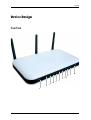
Device Design
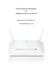
Front Panel
H
G
C
D
E
F
B
A
Page 7 of 66
User Manual
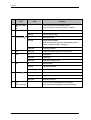
Label
A
Action
Simple Connect Button
Description
Press for 2 seconds to create or join a HomePlug AV network.
Press for 10 seconds to reset the Private Network Name to a random key.
B
C
Power
Powerline Activity
Off
No power is supplied to the device
Steady light
Connected to an AC power supply
Off
No Homeplug connection
Steady light
Homeplug connection established
The LED colors represents the connection rate within the HomePlug AV network
whether it is good (red), better (amber), or best (green).
Blinking light
Transmitting/Receiving data
D
USB
Blinking light
Will blink 3 times indicating Windows Connect Now (WCN) Process
E
WLAN
Off
Wireless Disabled
Steady Light
Wireless Enabled
Blinking light
Transmitting/Receiving data wirelessly
Off
No modem connection
Steady light
Connected to an active modem
Blinking light
Transmitting/Receiving data
Off
No Ethernet connection
Steady light
Connected to an active Ethernet device
Blinking light
Transmitting/Receiving data
F
G
H
Page 8 of 66
WAN
Ethernet 1-4
WPS
Press for two seconds (or until the LED blinks) to start WPS pairing.
(Wi-Fi Protected Setup)
Wireless client must be WPS-enabled and must be pressed within 3 minutes.
User Manual
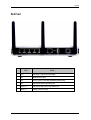
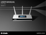
Back Panel
Label
Used for…
1
Power
Connecting the +12VDC, 1.67A DC power adapter
2
USB
Windows Connect Now (WCN)
3
Reset
Press for 2 seconds to reset the Router and HomePlug to default settings.
4
WAN
Connecting with a modem using an Ethernet cable
5
Ethernet 1-4
Connecting with computers/devices using an Ethernet cable
6
Antenna 1-3
Sending/receiving wireless signals
Page 9 of 66
User Manual
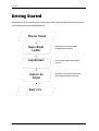
Getting Started
Setting up the device is easy. The flowchart below provides an outline of the steps needed to complete the installation. Brief descriptions appear beside
each step. Detailed instructions are provided in the subsequent pages.
Plan your Network
Remove/Disable
Conflicts
Setup the Router
Connect to the
Internet
Ready to Use
Page 10 of 66
You may need to check some setting or disable
some application before installation.
Connect the modem, computer, and power adaptor
to the router.
Open a browser to access the Web User Interface and
then use Setup Wizard to connect to the Internet.
User Manual
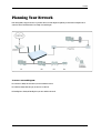
Planning Your Network
Before moving ahead to setup your network, it is a good idea to draw out a network diagram to help identify your network devices and plan out how to
connect these devices. The illustration below is an example of a network diagram.
To create a network diagram:
For wireless devices, identify the wireless devices you want to include in the network
For wired devices, identify which router port you want to use for each device.
For HomePlug devices, identify the HomePlug devices you want to include in the network.
Page 11 of 66
User Manual
Remove or Disable Conflicts
To make sure the router installation moves on smoothly, you need to remove or disable conflicts that may interfere the installation. Probable conflicts
may include:
Internet sharing applications
Proxy software
Security software
TCP/IP settings
Internet properties
Temporary Internet files
Internet Sharing, Proxy, and Security Applications
Internet sharing, proxy software, and firewall applications may interfere with the router installation. These should be removed or disabled before start
the installation.
If you have any of the following or similar applications installed on your computer, remove or disable them according to the manufacturer’s instructions.
Internet Sharing Applications
Proxy Software
Security Software
Microsoft Internet Sharing
WinGate
Symantec
WinProxy
Zone Alarm
Page 12 of 66
User Manual
Configuring TCP/IP Settings
Check if your computer uses the default TCP/IP settings.
To check the TCP/IP properties:
Click the Start button, and then click Run. This opens the Run dialog box.
Type control ncpa.cpl, and then click OK. This opens the Network Connections in your computer.
Right-click LAN, and then select Properties. This opens the Local Area Connection Properties dialog box.
Select Internet Protocol (TCP/IP), and then click Properties. This opens the Internet Protocol (TCP/IP) dialog box.
Check Obtain an IP address automatically.
To close the Internet Protocol (TCP/IP) dialog box, click OK.
To close the Local Area Connection Properties dialog box, click OK.
Configuring Internet Properties
To set the Internet Properties:
Click the Start button, and then click Run. This opens the Run dialog box.
Type control inetcpl.cpl, and then click OK. This opens Internet Properties.
Click Connections tab.
In Dial-up and Virtual Private Network settings, check Never dial a connection.
To close Internet Properties, click OK.
Page 13 of 66
User Manual
Removing Temporary Internet Files
Temporary Internet files are files from Web sites that are stored in your computer. Delete these files to clean the cache and remove footprints left by the
Web pages you visited.
To remove temporary Internet files:
Click the Start button, and then click Run. This opens the Run dialog box.
Type control, and then click OK. This opens Control Panel.
Double-click Internet Options. This opens Internet Options.
In the Temporary Internet Files pane, click Delete Cookies.
Click Delete Files.
To close Internet Properties, click OK.
Page 14 of 66
User Manual
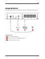
Setup the Device
When installing the router, find an area where there are enough electrical outlets for the router, the main computer, and your other computer devices.
To setup the router:
Use an Ethernet cable to connect a modem to the WAN port.
Use an Ethernet cable to connect a computer to any of the available Ethernet ports from 1-4.
Connect the power adapter and then plug it to an electrical source.
Page 15 of 66
User Manual
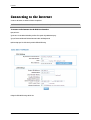
Connecting to the Internet
To connect to the Internet, use the Web User Interface’s Setup Wizard.
Note: To connect to the Internet, make sure that your router is connected to a modem and you have an active Internet service account.
To connect to the Internet via the Web User Interface:
Open your browser.
Type 192.168.1.1 in the address field and then press Enter. This opens the Log In Authentication page.
Type your Username and Password. The default username is admin, with blank password.
Quick Start Setup opens. You will be asked to provide the WAN and LAN Settings.
Configure the WAN and LAN settings, and click Next.
Page 16 of 66
User Manual
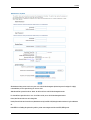
Configure the Wireless Network Settings including the Wireless Security Mode and click Finish.
After you click Finish, the router will save the new settings and then try to establish a connection with your Internet service provider.
To verify if your connection has been successful, click Product Info under the Basic Menu. A WAN IP address will appear under the WAN Connection
Information pane.
Page 17 of 66
User Manual
Connecting Wireless Devices
Manual Setup
Using WPS (Wi-Fi Protected Setup)
Using WCN (Windows Connect Now)
Manual Setup
After you setup the Router settings through the main computer, you can connect other devices with wireless capabilities. Wireless devices relieve you from
the task of laying out cables and allow you to use the Internet connection from your router.
To connect with wireless devices:
Turn on your wireless device.
Open the software you use to detect a wireless connection. This opens a window to ask for the connection settings.
Enter the connection settings for the wireless network. These settings are defined in your router during setup.
Page 18 of 66
User Manual
WPS (Wi-Fi Protected Setup)
WPS button allows you to enable Wi-Fi Protected Setup (WPS). When enabled, Wi-Fi Protected Setup automatically detects and connects wireless clients
into the wireless network by broadcasting the wireless network settings from your Access Point to you wireless device/s.
To setup WPS:
Press the WPS button on the router for two seconds, or until the LED blinks
Within 3 minutes, press the WPS button on the Wireless Client.
Note: WPS can only be used with wireless client devices that have a compatible WPS component.
WCN (Windows Connect Now)
WCN (Windows Connect Now) technology allows users to easily create a wireless network and add additional wireless devices using a USB flash drive.
With Windows Connect Now, users running Windows XP Service Pack 2 and later Windows OS version can create wireless network configuration settings
and transmit them to the access point and other wireless devices.
To setup WCN (Windows Connect Now):
Click Start and then click Control Panel.
For Control Panel Category View: click Network and Internet Connections, and then click Wireless Network Setup Wizard.
For Control Panel Classic View: click Wireless Network Setup Wizard.
Follow the instructions on your screen.
Choose "Use a USB flash drive"
Insert the USB Flash drive into your computer. Wireless network configuration settings will be saved to the flash drive.
Plug the flash drive into your Access Point, wireless client or Windows Connect Now compatible device that you want to add to the wireless network.
Note: Windows Connect Now can only be used with WCN compatible devices.
Page 19 of 66
User Manual
Creating a HomePlug AV Network
HomePlug AV utilizes the existing electrical wiring in the house as a path to create a secured network of computers and Ethernet devices. With a
maximum data rate of up to 200 Mbps, HomePlug AV can reliably handle high requirement applications like broadband Internet, high definition video
streaming, and Voice over IP. HomePlug AV converts digital signals to a complex analog signal that traverses along the electrical wires. When receiving
the analog signal, HomePlug AV converts the analog signal back to digital. To make the signal secured, a 128-bit AES encryption is applied.
To create a HomePlug AV network, you need at least two HomePlug AV devices using random Private Network Names. When you press Simple Connect
on both devices, a common Private Network Name will be automatically generated to enable them to communicate with each other.
When a HomePlug AV communicates with another device, the Powerline Activity LED
color will give you an idea about the connection rate: red means
below 40 Mbps; amber means 40 to 105 Mbps; and green means more than 105 Mbps.
Using Simple Connect Button
Simple Connect
provides a more convenient way of creating your HomePlug AV network without the need to open the HomePlug AV Utility software
from a computer.
To create a HomePlug AV network using Simple Connect:
Plug your HomePlug AV adaptor near your Router where you can easily observe the LED behavior.
Upon connection, the LEDs will blink simultaneously and then the Power LED
Press Simple Connect
blink, press the button
lights on steadily.
for two seconds on your Router. After you release the button, the Simple Connect
will blink. If the Simple Connect
did not
again for two seconds.
Note: Do not press Simple Connect for more than 2 seconds.
Press Simple Connect for two seconds on your HomePlug AV adaptor. After you release the button, the Simple Connect
did not blink, press button
will blink. If the Simple Connect
again for two seconds.
Make sure to press Simple Connect on your HomePlug AV adaptor within two minutes after you press Simple Connect on your Router. The LEDs on both
devices will switch off and on twice to signify that they are searching for another device to pair with.
To confirm if the connection was established, check the LEDs. The Power LEDs and the Powerline Activity LEDs on your Router and HomePlug Adaptor
are on. When the Powerline Activity LED on either Router or HomePlug Adaptor is off, this means the pairing is not successful. In this case, press the
Simple Connect button for 10 seconds (or until all the LEDs turns Off and On) to reset to a random Private Network Name, and redo the Pairing process.
Unplug the HomePlug AV adaptor and then connect it to your Ethernet-enabled device using an Ethernet cable. After connecting the Ethernet cable, plug
the HomePlug adaptor directly to a wall outlet.
Page 20 of 66
User Manual
Note: HomePlug AVs work best when connected directly to a wall socket. Avoid plugging it to a power strip or power extension. Other electrical devices in
the power strip produce electrical noise that may affect the performance of the HomePlug.
Using HomePlug AV Utility
HomePlug AV Utility is a software application that allows you to configure HomePlug AV. To create a HomePlug AV network using HomePlug AV Utility:
Install HomePlug AV Utility to your computer. Utility installer can be found in the Resource CD included with your Router.
After installation, click the Start button, click Programs, click HomePlug AV, click HomePlug AV Ethernet Adapter, and then click HomePlug AV Utility.
Select Private Network Name Tab.
Type the new Private Network Name. This field is case sensitive. It accepts 8 to 64 alphanumeric characters including punctuation marks but no spaces.
Page 21 of 66
User Manual
Click Apply. When the process is complete, the message Settings Applied appears.
To setup the Private Network Name of a remote HomePlug AV Adaptor:
Select Change Private Network Name of remote device.
Type the Device ID of the remote device. The Device ID can be found on the label pasted on the device.
Click Apply. When the process is complete, the message Settings Applied appears.
Page 22 of 66
User Manual
About the Web User Interface
The Web User Interface gives you the capability to configure the router settings. It is divided into the following sections:
Basic Menu
Advanced Menu
Maintenance Menu
To access the Web User Interface:
Open a browser after setting up the device.
Enter 192.168.1.1.
Enter the User Name and Password. The default User Name is admin, and the Password is blank.
Page 23 of 66
User Manual
Menus
The Web User Interface includes the following menus:
Basic Menu
Provides the Setup Wizard link and Product Information.
Advanced Menu
The Advanced Menu provides advanced router configuration settings.
Maintenance
The Maintenance Menu provides System Settings and Firmware Upgrade feature.
Page 24 of 66
User Manual
Basic Menu
The options for the Basic Menu include:
Quick Start
Product Info
WPS
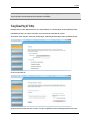
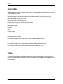
Quick Start
Setup Wizard gives you the ability to instantly connect to the Internet and configure the Web User Interface settings.
Page 25 of 66
User Manual
To use Quick Start:
Under Basic Menu, click Quick Setup. This opens the Setup Wizard.
Configure the WAN and LAN Settings, and click Next.
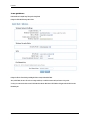
Configure the Wireless Network Settings including the Wireless Security Mode and click Finish.
After you click Finish, the router will save the new settings and then try to establish a connection with your Internet service provider.
To verify if your connection has been successful, click Product Info under the Basic Menu. A WAN IP address will appear under the WAN Connection
Information pane.
Page 26 of 66
User Manual
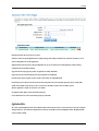
Product Info
The Product Info page provides a one-page summary about the Connection Information, Router Information, Local Network Information, and Wireless
Network settings.
Page 27 of 66
User Manual
WAN Information
The Connection Information pane gives you an idea about the status of your Internet connection. This pane includes a Renew/Release button or
Connect/Disconnect button (depending on your WAN Connection Type. When clicked, the router makes an attempt to connect to the Internet using the
parameters saved in the router.
LAN Information
This pane provides all the necessary information to determine the firmware version, LAN MAC Address, LAN IP Address, and DHCP Server status.
Wireless LAN Information
This pane displays the current wireless configuration settings for the router’s access point.
LAN Computers
Displays the MAC Address, Computer Name, and IP Address of Computers connected to the Router.
IGMP Multicast memberships
If IGMP is enabled, this area of the screen shows all multicast groups of which any LAN devices are members.
Page 28 of 66
User Manual
Advanced Menu
The options for the Advanced Menu include:
QoS
NAT
Routing
Security
Wireless
Applications
Status
QoS
QoS options include:
StreamEngine
WISH
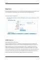
StreamEngine
The StreamEngine feature helps improve your network performance by prioritizing applications.
Page 29 of 66
User Manual
WAN Traffic Shaping
Enable Traffic Shaping When this option is enabled, the router restricts the flow of outbound traffic so as not to exceed the WAN uplink bandwidth.
Automatic Uplink Speed When enabled, this option causes the router to automatically measure the useful uplink bandwidth each time the WAN interface
is re-established (after a reboot, for example).
Measured Uplink Speed This is the uplink speed measured when the WAN interface was last re-established. The value may be lower than that reported by
your ISP as it does not include all of the network protocol overheads associated with your ISP's network. Typically, this figure will be between 87% and
91% of the stated uplink speed for xDSL connections and around 5 kbps lower for cable network connections.
Page 30 of 66
User Manual
Manual Uplink Speed If Automatic Uplink Speed is disabled, this options allows you to set the uplink speed manually. Uplink speed is the speed at which
data can be transferred from the router to your ISP. This is determined by your ISP. ISPs often specify speed as a downlink/uplink pair; for example,
1.5Mbps/284kbps. For this example, you would enter "284".
Connection Type By default, the router automatically determines whether the underlying connection is an xDSL/Frame-relay network or some other
connection type (such as cable modem or Ethernet), and it displays the result as Detected xDSL or Frame Relay Network. If you have an unusual network
connection in which you are actually connected via xDSL but for which you configure either "Static" or "DHCP" in the WAN settings, setting this option to
xDSL or Other Frame Relay Network ensures that the router will recognize that it needs to shape traffic slightly differently in order to give the best
performance. Choosing xDSL or Other Frame Relay Network causes the measured uplink speed to be reported slightly lower than before on such
connections, but gives much better results.
Detected xDSL or Frame Relay Network When Connection Type is set to Auto-detect, the automatically detected connection type is displayed here.
StreamEngine Setup
Enable StreamEngine Enable this option for better performance and experience with online games and other interactive applications, such as VoIP.
Automatic Classification This option is enabled by default so that your router will automatically determine which programs should have network priority.
For best performance, use the Automatic Classification option to automatically set the priority for your applications.
Dynamic Fragmentation This option should be enabled when you have a slow Internet uplink. It helps to reduce the impact that large low priority network
packets can have on more urgent ones by breaking the large packets into several smaller packets.
Add/Edit StreamEngine Rules
A StreamEngine Rule identifies a specific message flow and assigns a priority to that flow. For most applications, automatic classification will be
adequate, and specific StreamEngine Rules will not be required.
StreamEngine supports overlaps between rules, where more than one rule can match for a specific message flow. If more than one rule is found to match
the rule with the highest priority will be used.
Enable Specifies whether the entry will be active or inactive.
Name Create a name for the rule that is meaningful to you.
Priority The priority of the message flow is entered here -- 0 receives the highest priority (most urgent) and 255 receives the lowest priority (least
urgent).
Protocol The protocol used by the messages.
Local IP Range The rule applies to a flow of messages whose LAN-side IP address falls within the range set here.
Local Port Range The rule applies to a flow of messages whose LAN-side port number is within the range set here.
Remote IP Range The rule applies to a flow of messages whose WAN-side IP address falls within the range set here.
Remote Port Range The rule applies to a flow of messages whose WAN-side port number is within the range set here.
Page 31 of 66
User Manual
Save/Update Record the changes you have made into the following list.
Clear Re-initialize this area of the screen, discarding any changes you have made.
StreamEngine Rules
This section lists all the defined StreamEngine Rules. Click the Enable checkbox at the left to directly activate or de-activate the entry. An entry can be
changed by clicking the Edit icon or can be deleted by clicking the Delete icon. When you click the Edit icon, the item is highlighted, and the "Edit
StreamEngine Rule" section is activated for editing.
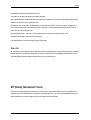
WISH
WISH is short for Wireless Intelligent Stream Handling, a technology developed to enhance your experience of using a wireless network by prioritizing the
traffic of different applications.
Page 32 of 66
User Manual
WISH
Enable WISH Enable this option if you want to allow WISH to prioritize your traffic.
Priority Classifiers
HTTP Allows the router to recognize HTTP transfers for many common audio and video streams and prioritize them above other traffic. Such streams are
frequently used by digital media players.
Windows Media Center Enables the router to recognize certain audio and video streams generated by a Windows Media Center PC and to prioritize these
above other traffic. Such streams are used by systems known as Windows Media Extenders, such as the Xbox 360.
Automatic When enabled, this option causes the router to automatically attempt to prioritize traffic streams that it doesn't otherwise recognize, based on
the behaviour that the streams exhibit. This acts to deprioritize streams that exhibit bulk transfer characteristics, such as file transfers, while leaving
interactive traffic, such as gaming or VoIP, running at a normal priority.
Page 33 of 66
User Manual
Add/Edit WISH Rule
A WISH Rule identifies a specific message flow and assigns a priority to that flow. For most applications, the priority classifiers ensure the right priorities
and specific WISH Rules are not required.
WISH supports overlaps between rules. If more than one rule matches for a specific message flow, the rule with the highest priority will be used.
Enable Specifies whether the entry will be active or inactive.
Name Create a name for the rule that is meaningful to you.
Priority The priority of the message flow is entered here. Four priorities are defined:
BK: Background (least urgent).
BE: Best Effort.
VI: Video.
VO: Voice (most urgent).
Protocol The protocol used by the messages.
Host 1 IP Range The rule applies to a flow of messages for which one computer's IP address falls within the range set here.
Host 1 Port Range The rule applies to a flow of messages for which host 1's port number is within the range set here.
Host 2 IP Range The rule applies to a flow of messages for which the other computer's IP address falls within the range set here.
Host 2 Port Range The rule applies to a flow of messages for which host 2's port number is within the range set here.
Save/Update Record the changes you have made into the following list.
Clear Re-initialize this area of the screen, discarding any changes you have made.
WISH Rules
This section lists the defined WISH Rules. Click the Enable checkbox at the left to directly activate or de-activate the entry. An entry can be changed by
clicking the Edit icon or can be deleted by clicking the Delete icon. When you click the Edit icon, the item is highlighted, and the "Edit WISH Rule" section
is activated for editing.
Page 34 of 66
User Manual
NAT (Network Address Translation)
NAT options include:
Port Forwarding
Port Trigger
Virtual Server
DMZ
Port Forwarding
Multiple connections are required by some applications, such as internet games, video conferencing, Internet telephony, and others. These applications
have difficulties working through NAT (Network Address Translation). This section is used to open multiple ports or a range of ports in your router and
redirect data through those ports to a single PC on your network. You can enter ports in various formats:
Range(50-100)
Individual(80,68,888)
Mixed (1020-5000, 689)
Page 35 of 66
User Manual
Add/Edit Port Forwarding Rule
Use this section to add a Port Forwarding Rule to the following list or to edit a rule already in the list.
Enable Specifies whether the entry will be active or inactive.
Name Give the rule a name that is meaningful to you, for example Game Server. You can also select from a list of popular games, and many of the
remaining configuration values will be filled in accordingly. However, you should check whether the port values have changed since this list was created,
and you must fill in the IP address field.
IP Address Enter the local network IP address of the system hosting the server, for example 192.168.0.50. You can select a computer from the list of
DHCP clients in the "Computer Name" drop-down menu, or you can manually enter the IP address of the server computer.
TCP Ports Enter the TCP ports to open (for example 6159-6180, 99).
UDP Ports Enter the UDP ports to open (for example 6159-6180, 99).
Schedule Select a schedule for the times when this rule is in effect. If you do not see the schedule you need in the list of schedules, go to the
Advanced>Applications>Schedule screen and create a new schedule.
Inbound Filter Select a filter that controls access as needed for this rule. If you do not see the filter you need in the list of filters, go to the
Advanced>Security>Inbound Filter screen and create a new filter.
Save/Update Record the changes you have made into the following list.
Clear Re-initialize this area of the screen, discarding any changes you have made.
Note that different LAN computers cannot be associated with Port Forwarding rules that contain any ports in common; such rules would contradict each
other.
Port Forwarding Rules
This is a list of the defined Port Forwarding Rules. Click the Enable checkbox at the left to directly activate or de-activate the entry. An entry can be
changed by clicking the Edit icon or can be deleted by clicking the Delete icon. When you click the Edit icon, the item is highlighted, and the "Edit Port
Forwarding Rule" section is activated for editing.
Port Trigger
Port Trigger rule is used to open single or multiple ports on your router when the router senses data sent to the Internet on a "trigger" port or port
range. An application rule applies to all computers on your internal network.
Page 36 of 66
User Manual
Enable Specifies whether the entry will be active or inactive.
Name Enter a name for the Special Application Rule, for example Game App, which will help you identify the rule in the future. Alternatively, you can
select from the Application list of common applications.
Application Instead of entering a name for the Special Application rule, you can select from this list of common applications, and the remaining
configuration values will be filled in accordingly.
Trigger Port Enter the outgoing port range used by your application (for example 6500-6700).
Trigger Traffic Type Select the outbound protocol used by your application (for example Both).
Firewall Port Enter the port range that you want to open up to Internet traffic (for example 6000-6200).
Firewall Traffic Type Select the protocol used by the Internet traffic coming back into the router through the opened port range (for example Both).
Schedule Select a schedule for when this rule is in effect. If you do not see the schedule you need in the list of schedules, go to the
Advanced>Applications>Schedule screen and create a new schedule.
Save/Update Record the changes you have made into the following list.
Clear Re-initialize this area of the screen, discarding any changes you have made.
Application Rules
This is a list of the defined application rules. Click the Enable checkbox at the left to directly activate or de-activate the entry. An entry can be changed by
clicking the Edit icon or can be deleted by clicking the Delete icon. When you click the Edit icon, the item is highlighted, and the "Edit Application Rule"
section is activated for editing.
Page 37 of 66
User Manual
Virtual Server
The Virtual Server option gives Internet users access to services on your LAN. This feature is useful for hosting online services such as FTP, Web, or game
servers. For each Virtual Server, you define a public port on your router for redirection to an internal LAN IP Address and LAN port.
Add/Edit Virtual Server
Enable Specifies whether the entry will be active or inactive.
Name Assign a meaningful name to the virtual server, for example Web Server. Several well-known types of virtual server are available from the
"Application Name" drop-down list. Selecting one of these entries fills some of the remaining parameters with standard values for that type of server.
IP Address The IP address of the system on your internal network that will provide the virtual service, for example 192.168.0.50. You can select a
computer from the list of DHCP clients in the "Computer Name" drop-down menu, or you can manually enter the IP address of the server computer.
Protocol Select the protocol used by the service. The common choices -- UDP, TCP, and both UDP and TCP -- can be selected from the drop-down menu. To
specify any other protocol, select "Other" from the list, then enter the corresponding protocol number (as assigned by the IANA) in the Protocol box.
Private Port The port that will be used on your internal network. Public Port The port that will be accessed from the Internet.
Page 38 of 66
User Manual
Schedule Select a schedule for when the service will be enabled. If you do not see the schedule you need in the list of schedules, go to the
Advanced>Applications>Schedule screen and create a new schedule.
Inbound Filter Select a filter that controls access as needed for this virtual server. If you do not see the filter you need in the list of filters, go to the
Advanced>Security>Inbound Filter screen and create a new filter.
Save/Update Record the changes you have made into the following list.
Clear Re-initialize this area of the screen, discarding any changes you have made.
Virtual Server List
This is a list of the defined Virtual Servers. Click the Enable checkbox at the left to directly activate or de-activate the entry. An entry can be changed by
clicking the Edit icon or can be deleted by clicking the Delete icon. When you click the Edit icon, the item is highlighted, and the "Edit Virtual Servers"
section is activated for editing.
DMZ
DMZ means "Demilitarized Zone." If an application has trouble working from behind the router, you can expose one computer to the Internet and run the
application on that computer.
When a LAN host is configured as a DMZ host, it becomes the destination for all incoming packets that do not match some other incoming session or rule.
If any other ingress rule is in place, that will be used instead of sending packets to the DMZ host; so, an active session, virtual server, active port trigger,
or port forwarding rule will take priority over sending a packet to the DMZ host. (The DMZ policy resembles a default port forwarding rule that forwards
every port that is not specifically sent anywhere else.)
Enable DMZ Checked by default.
DMZ IP Address Specify the LAN IP address of the LAN computer that you want to have unrestricted Internet communication. It is advisable for the
computer to have a Static IP Address so that the IP address of the DMZ computer does not change.
Page 39 of 66
User Manual
Routing
Routing options include:
Static
RIP
Static Routing
If the router is connected to more than one network, you may need to set up a static route between them. A static route is a pre-defined pathway that
network information must travel to reach a specific host or network. You can use static routing to allow different IP domain users to access the Internet
through the router.
The Destination IP is the address of the remote LAN network or host to which you want to assign a static route. Enter the IP address of the host for which
you wish to create a static route here. For a standard Class C IP domain, the network address is the first three fields of the New Destination IP, while the
last field should be 0.
The Subnet Mask identifies which portion of an IP address is the network portion, and which portion is the host portion. For a full Class C Subnet, the
Subnet Mask is 255.255.255.0. The Gateway IP address should be the IP address of the gateway device that allows for contact between the Gateway and
the remote network or host.
Add/Edit Route
Adds a new route to the IP routing table or edits an existing route.
Enable Specifies whether the entry will be enabled or disabled.
Page 40 of 66
User Manual
Destination IP The IP address of packets that will take this route.
Netmask One bits in the mask specify which bits of the IP address must match.
Gateway Specifies the next hop to be taken if this route is used. A gateway of 0.0.0.0 implies there is no next hop, and the IP address matched is directly
connected to the router on the interface specified: LAN or WAN.
Metric The route metric is a value from 1 to 16 that indicates the cost of using this route. A value of 1 is the lowest cost, and 15 is the highest cost. A
value of 16 indicates that the route is not reachable from this router. When trying to reach a particular destination, computers on your network will
select the best route, ignoring unreachable routes.
Interface Specifies the interface -- LAN or WAN -- that the IP packet must use to transit out of the router, when this route is used.
Save/Update Record the changes you have made into the following list.
Clear Re-initialize this area of the screen, discarding any changes you have made.
Routes List
The section shows the current routing table entries. Certain required routes are predefined and cannot be changed. Routes that you add can be changed by
clicking the Edit icon or can be deleted by clicking the Delete icon. When you click the Edit icon, the item is highlighted, and the "Edit Route" section is
activated for editing. Click the Enable checkbox at the left to directly activate or de-activate the entry.
RIP (Routing Information Protocol)
Use this section to configure the internal network settings of your router and also to configure the built-in DHCP Server to assign IP addresses to the
computers on your network. The IP Address that is configured here is the IP Address that you use to access the Web-based management interface. If you
change the IP Address here, you may need to adjust your PC's network settings to access the network again.
Page 41 of 66
User Manual
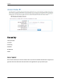
Security
Security options include:
Access Control
Firewall Settings
Inbound Filter
MAC Address filter
Web Filter
Access Control
The Access Control section allows you to control access in and out of devices on your network. Use this feature as Parental Controls to only grant access to
approved sites, limit web access based on time or dates, and/or block access from applications such as peer-to-peer utilities or games.
Page 42 of 66
User Manual
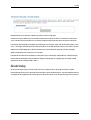
Enable By default, the Access Control feature is disabled. If you need Access Control, check this option.
Note: When Access Control is disabled, every device on the LAN has unrestricted access to the Internet. However, if you enable Access Control, Internet
access is restricted for those devices that have an Access Control Policy configured for them. All other devices have unrestricted access to the Internet.
Policy Wizard The Policy Wizard guides you through the steps of defining each access control policy. A policy is the "Who, What, When, and How" of access
control -- whose computer will be affected by the control, what internet addresses are controlled, when will the control be in effect, and how is the control
implemented. You can define multiple policies. The Policy Wizard starts when you click the button below and also when you edit an existing policy.
Add Policy Click this button to start creating a new access control policy.
Policy Table This section shows the currently defined access control policies. A policy can be changed by clicking the Edit icon, or deleted by clicking the
Delete icon. When you click the Edit icon, the Policy Wizard starts and guides you through the process of changing a policy. You can enable or disable
specific policies in the list by clicking the "Enable" checkbox.
Firewall Settings
The router provides a tight firewall by virtue of the way NAT works. Unless you configure the router to the contrary, the NAT does not respond to
unsolicited incoming requests on any port, thereby making your LAN invisible to Internet cyberattackers. However, some network applications cannot run
with a tight firewall. Those applications need to selectively open ports in the firewall to function correctly. The options on this page control several ways of
Page 43 of 66
User Manual
opening the firewall to address the needs of specific types of applications.
Firewall Settings
Enable SPI SPI ("stateful packet inspection" also known as "dynamic packet filtering") helps to prevent cyberattacks by tracking more state per session.
It validates that the traffic passing through that session conforms to the protocol. When the protocol is TCP, SPI checks that packet sequence numbers are
within the valid range for the session, discarding those packets that do not have valid sequence numbers.
Whether SPI is enabled or not, the router always tracks TCP connection states and ensures that each TCP packet's flags are valid for the current state.
Page 44 of 66
User Manual
NAT Endpoint Filtering
The NAT Endpoint Filtering options control how the router's NAT manages incoming connection requests to ports that are already being used.
Endpoint Independent Once a LAN-side application has created a connection through a specific port, the NAT will forward any incoming connection
requests with the same port to the LAN-side application regardless of their origin. This is the least restrictive option, giving the best connectivity and
allowing some applications (P2P applications in particular) to behave almost as if they are directly connected to the Internet.
Address Restricted The NAT forwards incoming connection requests to a LAN-side host only when they come from the same IP address with which a
connection was established. This allows the remote application to send data back through a port different from the one used when the outgoing session
was created.
Port And Address Restricted The NAT does not forward any incoming connection requests with the same port address as an already establish connection.
Note that some of these options can interact with other port restrictions. Endpoint Independent Filtering takes priority over inbound filters or schedules,
so it is possible for an incoming session request related to an outgoing session to enter through a port in spite of an active inbound filter on that port.
However, packets will be rejected as expected when sent to blocked ports (whether blocked by schedule or by inbound filter) for which there are no active
sessions. Port and Address Restricted Filtering ensures that inbound filters and schedules work precisely, but prevents some level of connectivity, and
therefore might require the use of port triggers, virtual servers, or port forwarding to open the ports needed by the application. Address Restricted
Filtering gives a compromise position, which avoids problems when communicating with certain other types of NAT router (symmetric NATs in particular)
but leaves inbound filters and scheduled access working as expected.
UDP Endpoint Filtering Controls endpoint filtering for packets of the UDP protocol.
TCP Endpoint Filtering Controls endpoint filtering for packets of the TCP protocol.
NAT Port Preservation
NAT Port preservation (on by default) tries to ensure that, when a LAN host makes an Internet connection, the same LAN port is also used as the Internet
visible port. This ensures best compatibility for internet communications.
Under some circumstances it may be desirable to turn off this feature.
Anti-Spoof checking
Enabling this option can provide protection from certain kinds of "spoofing" attacks.
Non-UDP/TCP/ICMP LAN Sessions
When a LAN application that uses a protocol other than UDP, TCP, or ICMP initiates a session to the Internet, the router's NAT can track such a session,
even though it does not recognize the protocol. This feature is useful because it enables certain applications (most importantly a single VPN connection to
a remote host) without the need for an ALG.
Note that this feature does not apply to the DMZ host (if one is enabled). The DMZ host always handles these kinds of sessions.
Page 45 of 66
User Manual
Application Level Gateway (ALG) Configuration
Here you can enable or disable ALGs. Some protocols and applications require special handling of the IP payload to make them work with network address
translation (NAT). Each ALG provides special handling for a specific protocol or application. A number of ALGs for common applications are enabled by
default.
PPTP
Allows multiple machines on the LAN to connect to their corporate networks using PPTP protocol. When the PPTP ALG is enabled, LAN computers can
establish PPTP VPN connections either with the same or with different VPN servers. When the PPTP ALG is disabled, the router allows VPN operation in a
restricted way -- LAN computers are typically able to establish VPN tunnels to different VPN Internet servers but not to the same server. The advantage of
disabling the PPTP ALG is to increase VPN performance.
IPSec (VPN)
Allows multiple VPN clients to connect to their corporate networks using IPSec. Some VPN clients support traversal of IPSec through NAT. This option may
interfere with the operation of such VPN clients. If you are having trouble connecting with your corporate network, try disabling this option.
Check with the system adminstrator of your corporate network whether your VPN client supports NAT traversal.
Note that L2TP VPN connections typically use IPSec to secure the connection. To achieve multiple VPN pass-through in this case, the IPSec ALG must be
enabled.
RTSP
Allows applications that use Real Time Streaming Protocol to receive streaming media from the internet. QuickTime and Real Player are some of the
common applications using this protocol.
Windows/MSN Messenger
Supports use on LAN computers of Microsoft Windows Messenger (the Internet messaging client that ships with Microsoft Windows) and MSN Messenger.
The SIP ALG must also be enabled when the Windows Messenger ALG is enabled.
FTP
Allows FTP clients and servers to transfer data across NAT. Refer to the Virtual Server page if you want to host an FTP server.
H.323 (Netmeeting)
Allows H.323 (specifically Microsoft Netmeeting) clients to communicate across NAT. Note that if you want your buddies to call you, you should also set
up a virtual server for NetMeeting.
SIP
Allows devices and applications using VoIP (Voice over IP) to communicate across NAT. Some VoIP applications and devices have the ability to discover
NAT devices and work around them. This ALG may interfere with the operation of such devices. If you are having trouble making VoIP calls, try turning
this ALG off.
Wake-On-LAN
Page 46 of 66
User Manual
This feature enables forwarding of "magic packets" (that is, specially formatted wake-up packets) from the WAN to a LAN computer or other device that is
"Wake on LAN" (WOL) capable. The WOL device must be defined as such on the Virtual Server Settings page. The LAN IP address for the virtual server is
typically set to the broadcast address 192.168.0.255. The computer on the LAN whose MAC address is contained in the magic packet will be awakened.
MMS
Allows Windows Media Player, using MMS protocol, to receive streaming media from the internet.
Inbound Filter
When you use the Virtual Server, Port Forwarding, or Remote Administration features to open specific ports to traffic from the Internet, you could be
increasing the exposure of your LAN to cyberattacks from the Internet. In these cases, you can use Inbound Filters to limit that exposure by specifying the
IP addresses of internet hosts that you trust to access your LAN through the ports that you have opened. You might, for example, only allow access to a
game server on your home LAN from the computers of friends whom you have invited to play the games on that server.
Add/Edit Inbound Filter Rule
Here you can add entries to the Inbound Filter Rules List below, or edit existing entries.
Name Enter a name for the rule that is meaningful to you.
Action The rule can either Allow or Deny messages.
Page 47 of 66
User Manual
Remote IP Range Define the ranges of Internet addresses this rule applies to. For a single IP address, enter the same address in both the Start and End
boxes. Up to eight ranges can be entered. The Enable checkbox allows you to turn on or off specific entries in the list of ranges.
Save/Update Record the changes you have made into the following list.
Clear Re-initialize this area of the screen, discarding any changes you have made.
Inbound Filter Rules List
The section lists the current Inbound Filter Rules. An entry can be changed by clicking the Edit icon or can be deleted by clicking the Delete icon. When
you click the Edit icon, the item is highlighted, and the "Edit Inbound Filter Rule" section is activated for editing.
In addition to the filters listed here, two predefined filters are available wherever inbound filters can be applied:
Allow All Permit any WAN user to access the related capability.
Deny All Prevent all WAN users from accessing the related capability. (LAN users are not affected by Inbound Filter Rules.)
MAC Address Filter (Network Filter)
The MAC address filter section can be used to filter network access by machines based on the unique MAC addresses of their network adapter(s). It is most
useful to prevent unauthorized wireless devices from connecting to your network. A MAC address is a unique ID assigned by the manufacturer of the
network adapter.
MAC Filtering Setup
Choose the type of MAC filtering needed.
Turn MAC Filtering OFF: When "OFF" is selected, MAC addresses are not used to control network access.
Turn MAC Filtering ON and ALLOW computers listed to access the network: When "ALLOW" is selected, only computers with MAC addresses listed in the
MAC Filtering Rules list are granted network access.
Page 48 of 66
User Manual
Turn MAC Filtering ON and DENY computers listed to access the network: When "DENY" is selected, any computer with a MAC address listed in the MAC
Filtering Rules list is refused access to the network.
Add MAC Filtering Rule
Use this section to add MAC addresses to the list below.
MAC Address Enter the MAC address of a computer that you want to control with MAC filtering. Computers that have obtained an IP address from the
router's DHCP server will be in the DHCP Client List. Select a device from the drop down menu.
Save Record the changes you have made into the following list.
MAC Filtering Rules This section lists the network devices that are under control of MAC filtering.
Website Filter
The Web sites listed here are used when the Web Filter option is enabled in Access Control Page.
Add Web Filtering Rule
This section is where you add the Web sites to be used for Access Control.
Website URL/Domain Enter the URL (address) of the Web Site that you want to allow; for example: google.com. Do not enter the http:// preceding the
URL. Enter the most inclusive domain; for example, enter google.com and access will be permitted to both www.google.com and support.google.com.
Save Record the changes you have made into the following list.
Note: Many web sites construct pages with images and content from other web sites. Access will be forbidden if you do not enable all the web sites used to
construct a page. For example, to access my.yahoo.com, you need to enable access to yahoo.com, yimg.com, and doubleclick.net.
Website Filtering Rules
The section lists the currently allowed web sites.
Page 49 of 66
User Manual
Applications
Applications options include:
DDNS
Schedules
Syslogs
Time
UPnP
DDNS (Dynamic DNS)
The Dynamic DNS feature allows you to host a server (Web, FTP, Game Server, etc.) using a domain name that you have purchased
(www.whateveryournameis.com) with your dynamically assigned IP address. Most broadband Internet Service Providers assign dynamic (changing) IP
addresses. When you use a Dynamic DNS service provider, your friends can enter your host name to connect to your server, no matter what your IP
address is.
Enable Dynamic DNS Enable this option only if you have purchased your own domain name and registered with a dynamic DNS service provider. The
following paramters are displayed when the option is enabled.
Page 50 of 66
User Manual
Server Address Select a dynamic DNS service provider from the pull-down list.
Host Name Enter your host name, fully qualified; for example: myhost.mydomain.net.
Username or Key Enter the username or key provided by your service provider. If the Dynamic DNS provider supplies only a key, enter that key in all three
fields.
Password or Key Enter the password or key provided by your service provider. If the Dynamic DNS provider supplies only a key, enter that key in all three
fields.
Verify Password or Key Re-type the password or key provided by your service provider. If the Dynamic DNS provider supplies only a key, enter that key in
all three fields.
Timeout The time between periodic updates to the Dynamic DNS, if your dynamic IP address has not changed. The timeout period is entered in hours.
Note: If a dynamic DNS update fails for any reason (for example, when incorrect parameters are entered), the router automatically disables the Dynamic
DNS feature and records the failure in the log.
Schedules
Schedules can be created for use with enforcing rules. For example, if you want to restrict web access to Mon-Fri from 3pm to 8pm, you could create a
schedule selecting Mon, Tue, Wed, Thu, and Fri and enter a Start Time of 3pm and End Time of 8pm.
Add/Edit Schedule Rule
In this section you can add entries to the Schedule Rules List below or edit existing entries.
Name Give the schedule a name that is meaningful to you, such as "Weekday rule".
Page 51 of 66
User Manual
Day(s) Place a checkmark in the boxes for the desired days or select the All Week radio button to select all seven days of the week.
All Day - 24 hrs Select this option if you want this schedule in effect all day for the selected day(s).
Start Time If you don't use the All Day option, then you enter the time here. The start time is entered in two fields. The first box is for the hour and the
second box is for the minute. Email events are normally triggered only by the start time.
End Time The end time is entered in the same format as the start time. The hour in the first box and the minutes in the second box. The end time is used
for most other rules, but is not normally used for email events.
Save/Update Record the changes you have made into the following list.
Clear Re-initialize this area of the screen, discarding any changes you have made.
Schedule Rules List
This section shows the currently defined Schedule Rules. An entry can be changed by clicking the Edit icon or can be deleted by clicking the Delete icon.
When you click the Edit icon, the item is highlighted, and the "Edit Schedule Rule" section is activated for editing.
Syslog
This section allows you to archive your log files to a Syslog Server.
Enable Logging to Syslog Server Enable this option if you have a syslog server currently running on the LAN and wish to send log messages to it.
Syslog Server IP Address Enter the LAN IP address of the Syslog Server.
Time
The Time Configuration option allows you to configure, update, and maintain the correct time on the router's internal system clock. From this section you
can set the time zone that you are in and set the Time Server. Daylight saving can also be configured to automatically adjust the time when needed.
Page 52 of 66
User Manual
Time Configuration
Current Router Time Displays the time currently maintained by the router. If this is not correct, use the following options to configure the time correctly.
Time Zone Select your local time zone from pull down menu.
Enable Daylight Saving Check this option if your location observes daylight saving time.
Daylight Saving Offset Select the time offset, if your location observes daylight saving time.
DST Start and DST End Select the starting and ending times for the change to and from daylight saving time. For example, suppose for DST Start you
select Month="Oct", Week="3rd", Day="Sun" and Time="2am". This is the same as saying: "Daylight saving starts on the third Sunday of October
at 2:00 AM."
Automatic Time Configuration
Enable NTP Server Select this option if you want to synchronize the router's clock to a Network Time Server over the Internet. If you are using schedules or
logs, this is the best way to ensure that the schedules and logs are kept accurate.
Page 53 of 66
User Manual
Note that, even when NTP Server is enabled, you must still choose a time zone and set the daylight saving parameters.
NTP Server Used Select a Network Time Server for synchronization. You can type in the address of a time server or select one from the list. If you have
trouble using one server, select another.
Set the Date and Time Manually
If you do not have the NTP Server option in effect, you can either manually set the time for your router here, or you can click the Copy PC’s Time button
to copy the time from the computer you are using. (Make sure that computer's time is set correctly.)
Note: If the router loses power for any reason, it cannot keep its clock running, and will not have the correct time when it is started again. To maintain
correct time for schedules and logs, either you must enter the correct time after you restart the router, or you must enable the NTP Server option.
UPnP
Universal Plug and Play, supports peer-to-peer Plug and Play functionality for network devices.
Page 54 of 66
User Manual
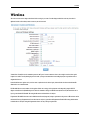
Wireless
The wireless section is used to configure the advanced wireless settings for your router. Note that changes made in this section may also need to be
duplicated on wireless clients that you want to connect to your wireless network.
Transmit Power Normally the wireless transmitter operates at 100% power. In some circumstances, however, there might be a need to isolate specific
frequencies to a smaller area. By reducing the power of the radio, you can prevent transmissions from reaching beyond your corporate/home office or
designated wireless area.
Beacon Period Beacons are packets sent by a wireless router to synchronize wireless devices. Specify a Beacon Period value between 20 and 1000. The
default value is set to 100 milliseconds.
RTS Threshold When an excessive number of wireless packet collisions are occurring, wireless performance can be improved by using the RTS/CTS
(Request to Send/Clear to Send) handshake protocol. The wireless transmitter will begin to send RTS frames (and wait for CTS) when data frame size in
bytes is greater than the RTS Threshold. This setting should remain at its default value of 2346 bytes.
Fragmentation Threshold Wireless frames can be divided into smaller units (fragments) to improve performance in the presence of RF interference and at
the limits of RF coverage. Fragmentation will occur when frame size in bytes is greater than the Fragmentation Threshold. This setting should remain at
its default value of 2346 bytes. Setting the Fragmentation value too low may result in poor performance.
Page 55 of 66
User Manual
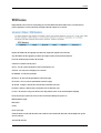
DTIM Interval A DTIM is a countdown informing clients of the next window for listening to broadcast and multicast messages. When the wireless router
has buffered broadcast or multicast messages for associated clients, it sends the next DTIM with a DTIM Interval value. Wireless clients detect the beacons
and awaken to receive the broadcast and multicast messages. The default value is 1. Valid settings are between 1 and 255.
802.11d Enable Enables 802.11d operation. 802.11d is a wireless specification for operation in additional regulatory domains. This supplement to the
802.11 specifications defines the physical layer requirements (channelization, hopping patterns, new values for current MIB attributes, and other
requirements to extend the operation of 802.11 WLANs to new regulatory domains (countries). The current 802.11 standard defines operation in only a
few regulatory domains (countries). This supplement adds the requirements and definitions necessary to allow 802.11 WLAN equipment to operate in
markets not served by the current standard. Enable this option if you are operating in one of these "additional regulatory domains".
Wireless Isolation Enabling Wireless Isolation prevents associated wireless clients from communicating with each other.
WMM Enable Enabling WMM can help control latency and jitter when transmitting multimedia content over a wireless connection.
A-MPDU Aggregation Aggregation of wireless packets based on MAC protocol data units is a technique for maximizing performance. This option should
normally be left enabled.
Short GI Using a short (400ns) guard interval can increase throughput. However, it can also increase error rate in some installations, due to increased
sensitivity to radio-frequency reflections. Select the option that works best for your installation.
WDS Enable When WDS is enabled, this access point functions as a wireless repeater and is able to wirelessly communicate with other APs via WDS links.
Note that WDS is incompatible with WPA -- both features cannot be used at the same time. A WDS link is bidirectional; so this AP must know the MAC
Address (creates the WDS link) of the other AP, and the other AP must have a WDS link back to this AP. Make sure the APs are configured with same
channel number.
WDS AP MAC Address Specifies one-half of the WDS link. The other AP must also have the MAC address of this AP to create the WDS link back to this AP.
Enter a MAC address for each of the other APs that you want to connect with WDS.
Enable Wireless This option turns off and on the wireless connection feature of the router. When you set this option, the following parameters are in
effect.
Channel Width The "Auto 20/40 MHz" option is usually best. The other options are available for special circumstances.
Transmission Rate By default the fastest possible transmission rate will be selected. You have the option of selecting the speed if necessary.
Visibility Status The Invisible option allows you to hide your wireless network. When this option is set to Visible, your wireless network name is broadcast
to anyone within the range of your signal. If you're not using encryption then they could connect to your network. When Invisible mode is enabled, you
must enter the Wireless Network Name (SSID) on the client manually to connect to the network.
Page 56 of 66
User Manual
Status
Status options includes:
Internet Sessions
Logs
Routing
Traffic Status
Wireless Clients
WISH Sessions
Internet Sessions
The Internet Sessions page displays full details of active Internet sessions through your router. An Internet session is a conversation between a program
or application on a LAN-side computer and a program or application on a WAN-side computer.
Local The IP address and, where appropriate, port number of the local application.
NAT The port number of the LAN-side application as viewed by the WAN-side application.
Internet The IP address and, where appropriate, port number of the application on the Internet.
Protocol The communications protocol used for the conversation.
State State for sessions that use the TCP protocol.
NO: None -- This entry is used as a placeholder for a future connection that may occur.
SS: SYN Sent -- One of the systems is attempting to start a connection.
EST: Established -- the connection is passing data.
FW: FIN Wait -- The client system has requested that the connection be stopped.
CW: Close Wait -- the server system has requested that the connection be stopped.
TW: Time Wait -- Waiting for a short time while a connection that was in FIN Wait is fully closed.
LA: Last ACK -- Waiting for a short time while a connection that was in Close Wait is fully closed.
CL: Closed -- The connection is no longer active but the session is being tracked in case there are any retransmitted packets still pending.
Page 57 of 66
User Manual
Dir The direction of initiation of the conversation:
Out Initiated from LAN to WAN.
In Initiated from WAN to LAN.
Priority The preference given to outbound packets of this conversation by the QoS Engine logic. Smaller numbers represent higher priority.
Time Out The number of seconds of idle time until the router considers the session terminated. The initial value of Time Out depends on the type and
state of the connection.
300 seconds UDP connections.
240 seconds Reset or closed TCP connections. The connection does not close instantly so that lingering packets can pass or the connection can be reestablished.
7800 seconds Established or closing TCP connections.
Logs
The router automatically logs (records) events of possible interest in its internal memory. If there is not enough internal memory for all events, logs of
older events are deleted, but logs of the latest events are retained. The Logs option allows you to view the router logs. You can define what types of events
you want to view and the level of events to view. This router also has external Syslog Server support so you can send the log files to a computer on your
network that is running a Syslog utility.
What to View
Select the kinds of events that you want to view.
Firewall and Security
Page 58 of 66
User Manual
System
Router Status
View Levels
Select the level of events that you want to view.
Critical
Warning
Informational
Apply Log Settings Now Click this button after changing Log Options to make them effective and permanent.
Refresh Clicking this button refreshes the display of log entries. There may be new events since the last time you accessed the log.
Clear Clicking this button erases all log entries.
Email Now Sends the router log to the configured email address.
Save Log Select this option to save the router log to a file on your computer.
Routing
Displays the Routing details configured for the Router.
Traffic Status
Displays traffic Statistics, receive and transmit packets passing through the router.
Page 59 of 66
User Manual
Wireless Clients
Allows you to view the wireless clients that are connected to your wireless router.
MAC Address The Ethernet ID (MAC address) of the wireless client.
IP Address The LAN-side IP address of the client.
Mode The transmission standard being used by the client. Values are 11a, 11b, 11g, or 11n for 802.11a, 802.11b, 802.11g, or 802.11n respectively.
Rate The actual transmission rate of the client in megabits per second.
Signal This is a relative measure of signal quality. The value is expressed as a percentage of theoretical best quality. Signal quality can be reduced by
distance, by interference from other radio-frequency sources (such as cordless telephones or neighboring wireless networks), and by obstacles between the
router and the wireless device.
Page 60 of 66
User Manual
WISH Sessions
Displays full details of active local wireless sessions through your router when WISH has been enabled. A WISH session is a conversation between a
program or application on a wirelessly connected LAN-side computer and another computer, however connected.
Originator The IP address and, where appropriate, port number of the computer that originated a network connection.
Target The IP address and, where appropriate, port number of the computer to which a network connection has been made.
Protocol The communications protocol used for the conversation.
State State for sessions that use the TCP protocol.
NO: None -- This entry is used as a placeholder for a future connection that may occur.
SS: SYN Sent -- One of the systems is attempting to start a connection.
EST: Established -- the connection is passing data.
FW: FIN Wait -- The client system has requested that the connection be stopped.
CW: Close Wait -- the server system has requested that the connection be stopped.
TW: Time Wait -- Waiting for a short time while a connection that was in FIN Wait is fully closed.
LA: Last ACK -- Waiting for a short time while a connection that was in Close Wait is fully closed.
CL: Closed -- The connection is no longer active but the session is being tracked in case there are any retransmitted packets still pending.
Priority The priority given to packets sent wirelessly over this conversation by the WISH logic. The priorities are:
BK: Background (least urgent).
BE: Best Effort.
VI: Video.
VO: Voice (most urgent).
Time Out The number of seconds of idle time until the router considers the session terminated. The initial value of Time Out depends on the type and
state of the connection.
300 seconds UDP connections.
Page 61 of 66
User Manual
240 seconds Reset or closed TCP connections. The connection does not close instantly so that lingering packets can pass or the connection can be reestablished.
7800 seconds Established or closing TCP connections.
Maintenance
Maintenance Menu includes:
System
Firmware Upgrade
Reboot
System
Page 62 of 66
User Manual
The Administrator Settings section is used to set-up secure access to the Web-based management. By default no password is configured. It is highly
recommended that you create a password to keep your new router secure.
Admin Password Enter a password for the user "admin", who will have full access to the Web-based management interface.
User Password Enter a password for the user "user", who will have read-only access to the Web-based management interface.
Gateway Name The name of the router can be changed here.
Inactivity Time Out If the router does not detect any administrative activity (from WAN or LAN) during this number of minutes, it logs the adminstrator
off.
Enable HTTPS Server Enabling this option makes it possible to perform remote management with the Secure HTTP (HTTPS) protocol.
Page 63 of 66
User Manual
Enable Remote Management Enabling Remote Management allows you to manage the router from anywhere on the Internet. Disabling Remote
Management allows you to manage the router only from computers on your LAN.
Remote Admin Port The port that you will use to address the management interface from the Internet. For example, if you specify port 1080 here, then,
to access the router from the Internet, you would use a URL of the form: http://my.domain.com:1080/.
Use HTTPS Setting this option requires all remote administration to use the Secure HTTP (HTTPS) protocol. For example, if you specify port 1080 above,
then, to access the router from the Internet, you would use a URL of the form: https://my.domain.com:1080/.
Remote Admin Inbound Filter Select a filter that controls access as needed for this admin port. If you do not see the filter you need in the list of filters,
go to the Inbound Filter Section screen and create a new filter.
System Settings
Restore to Factory Default
Allows you to reset the device to its factory settings.
Restore Defaults The Restore Defaults button will clear all user-entered modification and will reset the device settings back to its factory default values.
LAN IP address: 192.168.1.1
Username: admin Password: blank
Firmware Upgrade
The Upgrade Firmware page displays the Upgrade Firmware window so that you could update the latest firmware. Please make sure that you have
downloaded the latest and correct firmware from the product support website and store it in local drive.
Page 64 of 66
User Manual
To upgrade the latest firmware, click Browse to locate the firmware upgrade file, and then click Upload.
Please wait for 70 seconds.
Warning! Do not power off the unit when it is being upgraded.
Reboot
Click Reboot to reboot the device.
Page 65 of 66
User Manual
Safety Warnings
For your safety, be sure to read and follow all warning notices and instructions.
Do not open the device. Opening or removing the device cover can expose you to dangerous high voltage points or other risks. Only qualified service
personnel can service the device. Please contact your vendor for further information.
Do not use your device during a thunderstorm. There may be a risk of electric shock brought about by lightning.
Do not expose your device to dust or corrosive liquids.
Do not use this product near water sources.
Make sure to connect the cables to the correct ports.
Do not obstruct the ventilation slots on the device.
Page 66 of 66