1
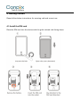
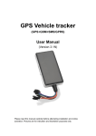
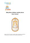
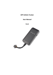
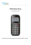
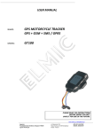
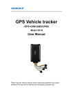
GPS Vehicle tracker
(GPS+GSM+SMS/GPRS)
User Manual
(Version 1.0)
This user manual has been specially designed to guide you through the functions and
features of your GPS vehicle tracker.
1. Accessories:
▶ Device
▶ Power cord
▶ Relay
▶ Microphone
▶ SOS alarm cable & button
▶ User Manual
2. Specifications
Dimension
91(L) x 52(W) x 19(H) mm
Weight
80g
Backup Battery
800mAh / 3.7V
Operation Temperature
-25℃-60℃
Humidity
5% - 95%
Standby Time
60hours
GSM Frequencies
850/900/1800/1900 MHz
GPRS
Class 12
GPS Channel
20
GPS Sensitivity
-165dBm
Acquisition Sensitivity
-148dBm
Position Accuracy
10m
Cold Start: <38s
Warm Start:<15s
TTFF (Open Sky)
Hot Start:<2s
GSM/GPS Antenna
Built-in design
LED Indicator
GSM-green, GPS-blue, Power-red
Data Transmit
TCP, SMS
Geo-fence
View any existing Geo-fence in the map
Speeding Alarm
Report when speeds higher than the pre-set value.
Low Power Alarm
Alarm when backup battery is running out
Non-movement Detection
Movement alarm based on built-in 3D motion sensor
Mileage Report
Track by time/distance interval
Remote Control
Cut off petrol/electricity
3. LED Indications
GPS LED Indicator - Blue
Slow Flashing (flash 1s every 3s)
Searching GPS signal
Flashing (flash 0.1s every 3s)
GPS fix
OFF
No GPS fix or initializing
GSM LED Indicator - Green
Quick flashing (interval 0.3s)
GSM initializing
Slow flashing (flash 1s every 3s)
Receive GSM signal normally
Flashing(flash 0.1s every 3s)
Connected to GSM network
Solid green
Calling
OFF
No GSM signal
Power Status - Red
Flashing (interval 0.3s)
Low battery
Slow flashing (flash 1s every 3s)
Full charge
Flashing (flash 0.1s every 3s)
Normal operating
Solid Red
Charging
OFF
Low battery/Power off
Ignition detection indication: three LED indicators take turns flashing.
4. Getting Started
Please follow below instructions for ensuring safe and correct use.
4.1 Install the SIM card
Place the SIM card into the device with the gold-colored side facing down.
Note: Make sure there is enough credit on the SIM card. If you will be using the GPRS
function, you should pay attention to the current SIM card GPRS charge.
4.2 Install the device
You need to choose somewhere that it won't be found, because the whole point of
fitting covert GPS vehicle tracker is the secrecy element.
Installation please refers to below picture.
NOTE:
1. Any high power devices such as reversing radar, anti-theft device or communication
equipment would affect the signal of the device.
2. All metallic cases of the windshield will attenuate the signal on the tracking device.
It’s simply due to the shielding effects of the metal compound of the case.
4.3 Device wiring diagram
Please choose the right relay (12V-standard / 24V-optional) for the proper installation.
Notes of the relay wiring
The relay wiring of pump: oil connectors of both ends are a fine white line (85) and a
fine yellow line (86). The fine white line (85) is connected to vehicle positive power
(+12V). The fine yellow line is connected to the device relay control line.
Cut off the positive connection line of the pump; then connect in series to the relay N.C.
contact (thick green line 87a) and the other end to relay COM contact (thick green line
30).
4.4 Power/ACC/Tele-cutoff (petrol/electricity) control line (4 pin)
1. Your device comes with a power cord and is designed to use only
manufacturer-specified original device. The red line is positive while the black one is
negative (the side should not be connect with ground wire).
2. The ACC line (orange) connects to ACC switch of the vehicle. Please be sure to
connect the ACC line; otherwise the device will enter ignition detection status when
disconnect the ACC line. If you don’t need to anti-theft temporarily, just connect the
ACC line to the positive side in parallel.
3. Tele-cutoff (petrol/ electricity) control line (yellow) is connected to pin 86 of the
Tele-cutoff (petrol/ electricity) relay (equal to the yellow line of the relay socket).
4. USB cable (3 pin)
Firmware updating interface/expanded function to reserve space.
5. MIC line (2 pin)
Externally connect to microphone for voice monitoring function.
6. SOS line (2 pin)
Externally connect to SOS switch for SOS function.
7. Multiple input and output
Number
Color
Definition
Function
Connect with the ACC of vehicle to detect the ignition; or
connected to the door triggering line for detecting status
(most vehicles from China, Japan and Korea are of negative
1
Brown
Digital input 1
triggering, and most from the US and Europe are of
positive triggering);
Input voltage: 0-50V;
Connect with the ACC of vehicle to detect the ignition; or
connected to the door triggering line for detecting status
(most vehicles from China, Japan and Korea are of negative
2
Grey
Digital input 2
triggering, and most from the US and Europe are of
positive triggering);
Input voltage: 0-50V;
Connect with external sensors, such as fuel/temperature
3
Purple
Analog input 1
sensor, etc.; Input voltage: 0-6V;
Ground, connected to the negative of the vehicle battery
4
Black
Ground
or to metallic cases of vehicle.
Used to connect with the external relay for remote fuel cut
off or engine immobilization;
Low voltage output (0V) when effective and open drain
output(OD) when ineffective;
5
Blue
Digital output 1
Maximum Current when Low Output Voltage
Supply(effective): 200mA;
Voltage range when output modes in open drain
(ineffective): 0-50V;
Used to connect with the external siren for multiple alarm
Low voltage output (0V) when effective and open drain
output(OD) when ineffective;
6
Green
Digital output 2
Maximum Current when Low Output Voltage
Supply(effective): 200mA;
Voltage range when output modes in open drain
(ineffective): 0-50V;
Power Supply Parameter: (V)
Rated Voltage
Range
Polarity Reverse Voltage
Max Voltage
12
9-16
14±0.1
24
24
18-32
28±0.2
36
36
27-48
42±0.2
54
5. Quick Operation Instructions
Operation Tips: To properly use the device, common parameters should be set before
initial use. This can be done by using the parameter editor or by sending SMS
commands to the device. (“,”should be English comma and no space before and after
the comma)
5.1 APN setting
To connect default platform http://www.gpsyeah.com , please send the SMS command
below: APN command format: APN,APN's Name#
E.g: APN, internet# (“internet” is the APN of carrier)
The device will reply “OK” if setting successfully.
Note: The APN of some countries have user name and password, you may need to send
SMS command as following:
APN, APN name, user name, password#
E.g: APN, internet, CLIENTE,AMENA#
5.2 DNS setting
To connect other platform, please send the two SMS commands below:
Command format:
SERVER,1, DNS, Port,0#
E.g:
SERVER,1,www.gpsluckly.com,8841,0#
It will reply “OK” after set successfully.
5.3 ON /OFF GPRS
When you want to disable GPRS, you can SMS command to the SIM card number which
used in the device.
Command format:
GPRS ON:GPRSON,1#
GPRS OFF:GPRSON,0#
It will reply “OK” after set successfully.
5.4 Add specific number
SMS command to the device to set the SOS number.
SOS,A,No.1, No.2, No.3#
“A” means to add new numbers, for example:
SOS,A,13510905991, 13510905992, 13510905993#
If there is only one SOS number, you can appoint a specific number as SOS number.
And the null means no adding.
For example:
SOS,A,13510905991#
means to set the first number as SOS number
SOS,A,,13510905992#
means to set the second number as SOS number
SOS,A,,,13510905993#
means to set the third number as SOS number
If set successfully, there is a “success” reply SMS.
5.5 Delete specific number
Before deleting specific number, please check its corresponding code. For the code,
please SMS “SOS#” to the device.
SMS command to the device to delete the number.
SOS,D, serial NO.1,serial NO.2,serial NO.3#
“D” means to delete the number, for example:
SOS,D,1# means to delete the first number
SOS,D,3# means to delete the third number
If you want to delete more than one numbers, you can send this command:
SOS,D,1,3# means to delete the first and third numbers.
If you forget serial number of the mobile number you want delete, you can send this
command:
SOS,D, mobile number# means to delete the mobile number directly.
For example:
SOS,D, 13527852360# means to delete the 13527852360 directly.
After deleting the SOS number, it will receive “Delete number 135XXXXXXXX success!
specific number total 2” for successful deleting of the specific number.
5.6 Set the center number
If you want to cut off/restore oil by SMS command, you have to set a center number
firstly. Only the center number can send the cut off/restore oil command to the device.
You can set your own mobile number as center number.
The command for setting center number is:
CENTER, A, mobile number#
For example: CENTER, A,15942703401#
If set successfully, there is an “OK” reply message.
NOTE:Only the SOS number can be used to set center number successfully.
5.7 Delete the center number
SMS command to the device to delete the center number.
The command is: CENTER,D#
For example: CENTER,D#
If set successfully, there is an “OK” reply SMS.
NOTE:Only the SOS number can be used to delete center number successfully.
Only SOS phone number can send this command successfully to set the center number.
There is only one center number can be set.
5.8 Check parameter setting
Send command to the terminal, you can check the parameter setting.
Command format: PARAM#
e.g.: PARAM#
Information replied:
IMEI: 353419032348877 ---IMEI number of the device;
Timer: 10,10; ---GPS data uploading Interval;
SENDS:5; --- the GPS working time when ACC is OFF;
SOS: 15942703401; --- SOS numbers, maximum 3 SOS numbers can be set and used
for alarm and monitoring;
Center Number: 15942703401; ---only 1 center number can be set and used for cutting
off /restoring oil command;
Sensorset:10,1,5,180 --- detect 5 vibrations in 10s; the alarm delay is 180s;
Defense time: 10; --- the defense delay is 10 minute;
TimeZone:E,8,0;
--- set time zone; default as E8.
The replied information contains IMEI number, GPS data uploading interval, SENDS,
SOS, center number, sensor set time interval, defense time and time zone.
5.9 Check GPRS parameters
SMS command format:GPRSSET#
Eg: GPRSSET#
Reply message:
GPRS: ON
//GPRS on/off status//
APN:,,;
//APN setting information//
Server:1,www.gpsluckly.com,8841,0;
//platform information//
URL:http://maps.google.com/maps?q=; //preset web link setting information //
5.10 GPS data uploading interval
The default sending interval is 10,10. It means when ACC ON , the device will upload
positioning data to platform server every 10s.when ACC OFF ,the device will upload
positioning data to platform server every 10s.
Users can modify sending interval by SMS
“TIMER,time1(seconds), time2(seconds)”
The time1&time2 ranges from 10-18000s
For example: TIMER,10,20#
It means when ACC ON , the device will upload positioning data to platform server
every 10s.when ACC OFF ,the device will upload positioning data to platform server
every 20s.
5.11 Sensor alarm time setting
When the vehicle power is off and ACC is in low-level, if ACC is off over 10 minutes, the
device will enter sensor alarm state. In this case, if the vehicle vibrates for a few times, it
will activate the vibration alarm system. If the vehicle battery is still not on (ACC is in
low level) after 3 minutes, the device will start vibration alarm.
SMS format: “DEFENSE,TIME(minutes)#” The time ranges from 1 to 60 mins.
For example: DEFENSE,15#. It means when ACC is in low level for 15mins, it will enter
sensor alarm status (vehicle power is off)
NOTE:
1. Preset SOS numbers when send SMS alarm messages and calls
2. If there is no need for vibration alarm, please SMS SENSOR,0# to close it.
5.12 Restore to factory setting
SMS command format: “FACTORY#” to set all parameter to default factory value.
Once received “OK”, it succeeds.
5.13 Reboot device
When there is something wrong with the link of GPRS, e.g., the parameter setting of the
device is correct, but you can't track the car on the platform. At this moment you can
send a command to the device to reboot the device.
The format is: RESET#
After receiving this command, the device will reboot after 1mins.
6. Operation of device
6.1 Power on/ Power off
Power on: Once insert a valid SIM card and connect all the wires, turn on the device,
then Power LED will flash first, During signal searching process, GSM and GPS LED will
flash. Once GPS LED keeps solid light, it means the device has been located and it starts
to work.
Power off: Just turn off the power switch.
The device will begin to upload positioning data to server once inserting a valid SIM
card and power on. During the working time, it can upload data to server every 10
seconds.
6.2 Check location
1. Via SMS
1.1 SMS “WHERE#”, to the SIM number of device. The device will send a location
message automatically. You can get the coordinates. If the device does not search any
information of location, it will send “No data” to the cell phone.
Example:
Lat:N22.571285,Lon:E113.877115,Course:42.20,Speed:0.0740,DateTime:10-11-23
22:28:51
1.2 SMS “URL#”, to the SIM number of device. The device will send a location Google
Map link. If the device does not search any information of location, it will send “No
data” to the cell phone.
Example:
<Date Time:10-11-23 23:42:51> http://maps.google.com/maps?q=N22.5714
90,E113.877103
POSITION:
<2014-7-30 11:12:13>http://maps.google.com/maps?q=N22.577120,E113.916738
2. Via platform
Go to the platform website offered by dealers to check your vehicle location.
6.3 SOS alarm
In emergent case, press SOS for 3s to activate SOS alarm. Then the device will send SOS
SMS to preset specific numbers and then dial the numbers in circles until the call is
picked up. At the meantime, the device will upload SOS alarm data to the server. And it
will send:
Emergency call , please Attention!<07-30 11:17>http://maps.google.com/maps?q=
N22.577120,E113.916738
Note: The specific numbers should be preset, just refer to 6.4.
6.4 Wire cut-off alarm
When the electricity supply of device is cut off, it will activate cut-off alarm. In this case,
the device will send related SMS to the specific numbers and dial the numbers in circles.
If nobody answers, the call just keeps 3 loops at most. At the meantime, the device will
upload SOS alarm data to the server. And it will send:
Cut Power! <07-28 17:35>http://maps.google.com/maps?q=N22.577108,E113.916763
Note: The specific numbers should be preset, just refer to 6.4.
6.5 Low battery alarm
When the device is only working with battery, once the internal voltage of battery is
less than 3.7V, device will send low battery alarm sms to specific number and alarm on
platform.
Low battery alarm sms content example:
“Attention! Battery too low, please charge.”
Which means the battery is to low, to inform user charging it in time.
Note: The specific numbers should be preset, just refer to 6.4.
6.6 Vibration alarm
The vibration alarm function is off by default. To activate this function, please send the
following command: SENALM,ON#. The alarm will be sent to both the service platform
and SOS numbers.
When vehicle power is off, ACC status is low, and if the lead time of low ACC is more
than 10 minutes (settable), device will activate security alarm. When the security alarm
is on, once the vehicle vibrates for several times, the alarm will be activated; in the next
3 minutes, if vehicle power is still off(ACC status is low), device will start alarm. At this
time, it will send alarm message to the service platform with the latitude and longitude,
while the platform will reply the Chinese address. Then the terminal will send vibration
alarm message to SOS numbers with the Chinese address, and call the SOS numbers in
cycle. If nobody answers, it will stop calling after 3 loops.
If the Chinese address can not be acquired for certain reason, the terminal will send a
message with the website link to the SOS numbers.
e.g.:
Sensor Alarm! <07-30
11:21>http://maps.google.com/maps?q=N22.577120,E113.916738
Note:
1. The SOS numbers should be preset.
2. Send “SENALM,OFF#” to turn off the vibration alarm.
6.7 Voice monitoring
When the special number cell phone dial device, ringing for 10 seconds, it will enter
voice monitoring status. At this time, caller can monitoring the sound in vehicle.
Incoming call from non special number will not activate voice monitoring function.
Note:
1. To realize this function, please set special number beforehand.
2. The SIM card put into the device should be equipped with caller identification.
6.8 Oil cut-off
1. Via platform
Send oil cut-off command on platform. To make sure the security of vehicle, tracker can
only indicate to cut off oil when GPS is in valid position status, and the speed is less
than 20KM/H or in static. Platform account password is needed when sending oil cut
off command.
2. Via SMS
Firstly, you should set a center number. Please refer to 6.6.Only center number can send
the command to the device to cut off and restore oil.
The format is: RELAY,1#
After the command is carried out, it will reply “Cut off the fuel supply: Success!
Speed:0 Km/h”. If the command didn't carry out, it will reply the reason about fail to
carry out.
Note:
To ensure the safety of the driver and the car, this command is valid only under two
conditions: the GPS is located; the speed is less than 20km/h.
6.9 Restoring Oil
1. Via platform
When the alarm is off, sending recover oil commands manually. Device will restore oil
supplying, and vehicle will work normally again.
Platform account password is needed when sending oil cut off command.
2. Via SMS
Only center number can send the command to the device to restore oil.
The format is: RELAY,0#
After the command is carried out, it will receive “Restore fuel supply: Success!”
6.10 Over speed Alarm
When the car is moving over a limited speed in average in a limited time period, then
the device will send over speed alarm SMS to user.
To turn on the over speed function, please send below SMS command: SPEED,ON/OFF,
Time,Limited speed,uploading mode#
Speed alarm switch: ON/OFF default: OFF
Time range (seconds): 5-600s(default as 20s)
Limited speed range(km/h):1-255km/h. default:100
Mode: 0/1. default: 1 way of alarming,0 means GPRS only,1 means SMS+GPRS
Example: SPEED,ON,20,100,1#
Means when the car is moving over 100km/h in average in 20 seconds, the device will
send over speed alarm to user
7.Web based tracking online activation
The GPRS web based tracking platform allows real time tracking with the latest Google
maps. There is also a playback feature that allows you to view where the vehicle has
been for up to 30 days in the past making it ideal for fleet management.
8.Trouble shooting
If you are having trouble with your device, try these troubleshooting procedures before
contacting a service professional.
Problems
Causes
Solutions
Fail to connect
The fuse blows
Replace the fuse
platform
ACC ignition disconnected
Turn on ACC with key
Wrong installation of SIM card
Check SIM card installation (Refer to 4.1 Install
SIM card)
Fail to connect
Filth on the SIM card iron surface
Clean it
Useless SIM
Contact internet service provider
Improper installation
Check installation of device (Refer to 4.2 Install
network
Fail to charge
the device)
Beyond GSM service area
Use it in effective GSM service offer area
Bad signal
Try again in a better signal area
The voltage is unsuitable
Connect with power with suitable voltage
Improper connection
Check connection with charger
Warranty instructions and service
1. The warranty is valid only when the warranty card is properly completed, and upon
presentation of the proof of purchase consisting of original invoice indicating the date of
purchase, model and serial No. of the product. We reserve the right to refuse warranty if this
information has been removed or changed after the original purchase of the product from
the dealer.
2. Our obligations are limited to repair of the defect or replacement the defective part or at its
discretion replacement of the product itself.
3. Warranty repairs must be carried out by our Authorized Service Centre. Warranty cover will
be void, even if a repair has been attempted by any unauthorized service centre.
4. Repair or replacement under the terms of this warranty does not provide right to extension
or renewal of the warranty period.
5. The warranty is not applicable to cases other than defects in material, design and
workmanship.
Maintenance Record
Date
Serviced by
Product Model
IMEI Number
Fault Descriptions
Comments
ShenZhen Concox Information Technology CO.,Ltd
Tel: +86 755 2912 1200
Fax: +86 755 2912 1290
E-mail: [email protected].
Add: 4/F, Building B, Gaoxinqi Industrial Park,
Liuxian 1st Road, No.67 Bao'an District, Shenzhen
www.iconcox.com