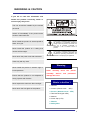
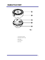
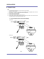
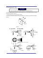
1
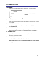
MINI SPEED DOME CAMERA
10X Mini Speed Dome Camera
Instruction Manual
Rev 1.05 dated on August 15st, 2007
CONTENTS
Warnings & Caution
What’s in the Box?
General Features
Names of Each Part
Installation
3
3
4
5
A. Connections
6
B. Ceiling Mount Type
7
C. Embedded Mount Type
8
D. Pipe Mount Type
10
E. Gooseneck Mount Type
12
F. Wall Mount Type
13
G. Corner Mount Type
15
H. Pole Mount Type
17
Quick Operating Keys
Diagnostic
OSD Menu Setting
18
20
21
A. OSD Menu Table
21
B. DOME SET
22
C. CAMERA SET
27
D. PRESET
29
E. AUTO SCAN SET
30
F. TOUR SET
31
G. PRIVACY SET
32
H. PATTERN SET
33
I. ALARM SET
34
J. SECTOR SET
35
DIP Switch Setting
36
A. Factory Default setting
36
B. ID Setting (1-ON,0-OFF)(1->10)
36
C. Protocol Setting
37
D. Baud Rate Setting
37
E. 485 Terminations
37
Trouble Shooting
Specification
Dimension
38
39
40
2
WARNINGS & CAUTION
If you fail to read this information and
handle the product incorrectly, death or
serious injury may occur.
The unit should be installed by the trained
personnel
Switch off immediately if the product emits
smoke or abnormal heat.
Never install the product in area exposed to
This symbol is intended to alert the user to
the presence of un-insulated “dangerous
voltage” within the product’s enclosure that
may be of sufficient magnitude to
constitute a risk of electric shock to
persons.
water, oil or gas.
Never install the product on a ceiling that
cannot hold its weight.
This symbol is intended to alert the user to
the presence of important operating and
maintenance (servicing) instructions in the
literature accompanying the appliance.
Never touch the power cord with wet hands.
Clean only with dry cloth.
Warning
Never install the product in extreme high or
low temperature.
Never
manually
assembly.
Ensure that the product is not subjected to
move
Serious
and
the
pan/tilt
permanent
damage will occur
strong impacts and vibration
Never expose the camera to direct sunlight
What’s in the Box ?
1. Camera
Never touch the front glass of the product.
2. Screws ( Ø4x16 screw
5EA )
3. Screws ( Ø3.5x30 screw 3EA )
4. Terminal block (5pin 2EA)
5. Manual
6. Screw Cap (1 EA)
7. Wrench
8. Safety Wire
3
GENERAL FEATURES
100X Zoom Mini Speed Dome
Quick Operation Keys
10X Optical Zoom with 10X digital zoom
This camera provides quick function keys to allow
control by most keyboards and DVRs that have Pelco
protocol support.
±0.02° dome system accuracy with full
micro step
Various Surveillance Functions
With 0.1° positional accuracy, the camera provides
excellent sensitive and delicate control. This is achieved by
full micro step motors and twin gear system
Auto Scan repeats pan and tilt between two preset
360° Endless Rotation
10X mini speed dome is capable of endless rotation of 360
degrees
Compensation function: preset position
The function provides absolute preset position even in
difficult applications where vibration and strong winds may
otherwise affect dome performance.
Over 200°/Sec Preset Speed
The 360° full pan function moves through a maximum of
200°/sec., enabling you to quickly pinpoint the spot you
want to watch. Tilt speed is also driven at 200°/sec on
preset seek.
Polarity Protection of Power (DC12V)
This protection function prevents damage to the domes
power board if the dc supply is connected with incorrect
polarity.
Filter changeable True Day/Night
Top quality images are assured under day and night
conditions due to the true day / night camera with IR cut
filter. Low light sensitivity is further increased by the
cameras digital slow shutter.
Indoor / Outdoor applications
The domes small size and construction to IP 66 ingress
protection rating make it ideal for internal or external
applications.
positions with different speed and dwell time.
8 Group Tour up to 8 Programmable Group tours are
available with each group is consisting of up to 60 preset
steps with different speed and dwell times along with 16
character titling.
165 Preset positions up to 165 programmable
preset positions are available with 16 character title.
8 Patterns up to 8 programmable user-defined patters
are available with 16 character title. Each can be up to
50 seconds long, giving a total of 400 seconds.
8 Sectors up to 8 programmable user-defined sectors
are available with 16 character titling.
4 Privacy Masking Zones up to 4 programmable
user-defined privacy masking zones are available.
4 Alarm input up to 4 alarms can be wired to the
dome head and can activate presets, tours, or patterns.
150°/S – Manual speed
The dome provides up to 150°/sec of manual speed and
is also adjustable from 100°/sec to 150°/sec in 10°/sec
increments.
1/4” Sony Super HAD CCD
Equipped with Sony Super HAD CCD technology, the
camera provides excellent sensitivity and low smear
levels.
Intelligent Pan/Tilt Controlling
Intelligent Pan/Tilt function is continually increases or
decreases pan and tilt speeds in proportion to zoom.
Dome Housing
The elegantly designed aluminum body and Poly
Carbonate dome cover provide a very solid product for a
wide range of applications.
.
Password Protection
It is possible to password protect all dome settings to
prevent unauthorized changes.
4
NAMES OF EACH PAR T
1. Surface Mount Adaptor
2. Cap Screw ( PT3/4 , 1EA )
3. Dip Switch
4. Terminal Block
5. Main body
5
INSTALLATION
A. CONNECTIONS
A-1
1.
2.
3.
4.
5.
6.
Loose the screws on the domes cover and remove it from the base.
(Screws won’t be removed)
Loosen the screws which connect mount cover and Main base and separate dome cover from
the main base. (These are captive screws that do not remove)
Connect power to Power and GND.
Connect video to video and GND.
Connect communication cable to RS-485 connectors.
Connect alarm common cables to GND. Connect the alarm input cables to their relevant terminal
(1-4) Alarm polarity can be programmed as N/O or N/C
z
Do not over tighten screws. This can cause damage.
-
12VDC type
-
24VAC type
FIG.2
6
B. CEILING MOUNT TYPE
FIG.4
FIG.3
1. Fix the surface mount adaptor with 4pcs of screws on the place where you want to
install. (FIG.3)
2. When you use pipe, please note the standard size of pipe. (FIG.4)
3. Re-assemble the dome.
FIG.5
7
C. EMBEDDED MOUNT TYPE
,
Contents
► Embedded mount bracket 1ea
► Holder 3ea
► Decoration cover 1ea
► Safety wire 1ea
► Screw – M3.0 x 6 5ea
► Screw - ø4.0 x 16 1ea
SUSPENSION
SAFETY WIRE HOLE
LOCK LEVER
LOCK LEVER
LOCK LEVER
LOCK LEVER
FIG.6
HOLDER
FIG.7
M3.0 SCREW
DECORATION COVER
CAMERA
FIG.8
1. Make a hole, 190mm, on the ceiling. (FIG.6)
8
2. Fold the lock levers and insert the bracket into the hole.
You can fix the lock lever by driving screws. (FIG.7)
3. Fix the decoration cover on the rear of camera by holder screws (M3.0) (FIG.8)
4. Hook the safety wire on the suspension and connect it to camera (FIG.9)
5. Install the camera by inserting cover lock and twisting it clockwise. (FIG.10)
6. Fix the decoration cover by screw (Ø4.0x16) (FIG.10)
FIG.9
FIG.10
9
D. PIPE MOUNT TYPE
Contents
► Pipe mount bracket 1ea
► Rubber 1ea
► Screw – M4.0 x 8 4ea
► Set anchor bolt (W5/16) 4ea
SCREW M4x8 (4ea)
BRACKET
(RUBBER BOTTOM VIEW)
RUBBER
BOTTOM COVER
FIG.11
1. As above FIG.11, assemble rubber and bracket on the bottom of camera.
2. After finishing assembly, it will be shown as below. (FIG.12)
FIG.12
3. If you want to install the speed dome on the concrete wall, you need to make 12.5mm
10
diameter 4 holes by drill like FIG. 13 (Depth 37mm)
4. Install SET ANCHOR BOLT on the holes.
5. As shown on FIG.14, after assembling mini PTZ and bottom cover assembly, drive the
pipe mount bracket and fix. (FIG.14)
FIG.2)
FIG.13
FIG.14
11
E.GOOSENECK MOUNT TYPE
Contents
► Gooseneck mount bracket 1ea
► Rubber 1ea
► Set anchor bolt (W5/16) 4ea
► Screw M4x8 4ea
FIG.15
1. If you want to install the speed dome on the concrete wall, you need to make 12.5mm
diameter 4 holes by drill like FIG.15 (Depth 37mm)
2. Install SET ANCHOR BOLT on the holes.
3. As shown on FIG.16, after assembling mini PTZ and bottom cover assembly, drive the
gooseneck mount bracket and fix. (FIG.16)
FIG.16
12
F.WALL MOUNT TYPE
Contents
► Wall mount bracket 1ea
► Set Anchor Bolt (W5/16) 4ea
► Hexagon Socket head cap screw M4.0 x16 4ea
1. If you want to install the speed dome on the concrete wall, you need to make 12.5mm
diameter 4 holes by drill like FIG. 1 ( Depth 37mm) (FIG.17)
2. Install SET ANCHOR BOLT on the holes.
3. To install Wall Mount Bracket
Tip> Select a ceiling board strong enough to hold 4 times the total weight of the camera
(Weight combined camera: approx.5kg)
FIG.17
<the cable into the ceiling>
<the cable out of the ceiling>
FIG.18
13
4. Assemble a wall mount bracket and camera by Hexagon socket head cap screws
(M4.0X16) (FIG.19)
HEXAGON SOCKET HEAD CAP
SCREW M4.0x16 4EA
FIG.19
14
G.CORNER MOUNT TYPE
Contents
► Corner mount adaptor 1ea ► Set Anchor Bolt (W5/16) 4ea ► M10 Bolt & Nut 4ea
1. First mark the positions of holes placing the corner mount bracket. (FIG.20)
2. Make 12.5mm diameter 4 holes by drill. (Depth 37mm)
3. Install SET ANCHOR BOLT on the holes.
4. Fix the wanted bracket on the corner mount bracket with 4 ea of M10 BOLT before you
install the corner mount bracket. (FIG.21)
5. Screw the set anchor bolt of the bracket by nut on the wall. (FIG.22)
FIG.20
FIG.22
FIG.21
6. After driving a bottom cover assembly to gooseneck mount bracket, as shown on FIG23,
15
assemble mini PTZ with bottom cover assembly. (FIG.23)
FIG.23
16
H.POLE MOUNT TYPE
Contents
► Pole mount adaptor 1ea ► Band Clamp 2ea ► M10 Bolt & Nut 4ea
1. Fix the wanted bracket on the pole mount bracket with 4 ea of M10 BOLT before you install
the pole mount bracket. (FIG.24)
2. Tie the bracket with SUS BAND tightly. (FIG.25)
3. As shown FIG.26 after installing a wall mount bracket, fix a camera on the wall mount bracket.
(FIG.26)
FIG.24
FIG.25
HEXAGON SOCKET HEAD CAP SCREW
M4.0x16 4EA
FIG.26
17
QUICK OPERATING KEYS
The dome supports Pelco D and Pelco P protocols.
The dome may be used with any controller or DVR etc that supports the Pelco D and Pelco P protocols.
The default setting of the dome is Pelco D / P (auto detection) with 2400 bps (baud rate).
[PELCO D/P, SAMSUNG PROTOCOLS]
The comprehensive feature set of the dome is available from Pelco compatible controllers via quick
operation keys as defined below.
1-64 + preset and 100~200 + preset are used for normal user presets. Presets 65-99 + are
reserved for special functions.
For example, to enter OSD MENU, press the button 95 +PRESET
<Quick Operation Key Table 1, Pelco D/P, SAMSUNG>
Number
1 ~ 64, 100~200 +Preset
65 + Preset
66 +Preset
67 +Preset
71~78 +Preset
81~88 +Preset
91 + Preset
92 + Preset
93 + Preset
94 + Preset
95 + Preset
96 + Preset
97 +Preset
Note
PRESET
PRESET STATUS
AUTO SCAN
AUTO FLIP
GROUP TOUR
PATTERN
ZERO POSITION
FREEZE
BLC MODE
D/N MODE
OSD MAIN MENU
FOCUS ADJUST
ALARM
Function
Execute Preset 1 ~ 64
Display Preset Status
Execute Auto Scan
Selectable On/Off/Auto in Auto Flip function
Execute Group Tour #1 ~ #8
Execute Pattern #1 ~ #8
Search For Pan / Tilt Zero Position
Select Freezing of current image
Selectable On/Off in BLC function
Selectable Day/Night Mode (Auto/Day/Night Mode)
To enter OSD Main Menu
Focus adjustment
Selectable Enable/Disable all Alarms
<Quick Operation Keys Table 2> Use these function keys if controller has these keys>
Menu
Tilt Up / Down
Pan Left / Right
Focus Near
Focus Far
Zoom Tele
Zoom Wide
Function
Sub menu cursor moves up / down
Enter to the sub menu or status change or decrement
Using for Enter key when user select YES or NO
Using for function changing keys when set coordinate
Status cursor to the right
Status cursor to the left
z
65 + preset:” Status Report” is displayed, to remove this screen, press Focus Near button.
z
92 + preset: This feature freezes the current live image during tour, auto scan or pattern
operation. When you press 92 + preset button, the image freezes but the camera is still
working as per operation such as tour, pattern or auto scan. To return to normal images,
press 92 + preset button again. This feature is operated by preset number but not included
in OSD main menu.
z
If a controller asks for an unsupported feature “Not available” is displayed on the monitor.
18
QUICK OPERATING KEYS
[VICON PROTOCOL]
If user wants to choose Vicon Protocol, the user may change the dip switch first.
(Refer to Page #36 DIP SWITCH SETTING - PROTOCOL)
Baud Rate: 4800 (Vicon default)
The operation system is almost same as Pelco D/P protocols but some special features are different way as
noted below’
<Quick Operation Key Table 2: VICON>
Number
1 ~ 79 +Preset
80~87 +Preset
88~89 +Preset
90 + Preset
90 + Preset Save
91 + Preset Save
92 + Preset Save
93 + Preset Save
94 + Preset Save
95 + Preset Save
96 + Preset Save
97 + Preset Save
98 + Preset Save
99 + Preset Save
Note
PRESET
GROUP TOUR
PATTERN
Focus Mode Set
Pan/Tilt Lockout
ZERO POSITION
ALARM
BLC MODE
OSD MAIN MENU
D/N MODE
SECTOR
DOME Reset
AUTO PAN
Pan/Tilt Speed
Function
Execute Preset 1 ~ 79
Execute Group Tour #1 ~ #8
Execute Pattern #1 ~ #2
Focus Mode Toggle to Auto or Manual
PAN/TILT Lock or Unlock setting
Search For Pan / Tilt Zero Position
Selectable Enable/Disable all Alarms
Selectable On/Off in BLC function
To enter OSD Main Menu
Selectable Day/Night Mode (Auto/Day/Night Mode)
SECTOR setting menu entrance
Initial DOME Reset - Rebooting
AUTO PAN setting menu entrance
Manual Pan/Tilt Max Speed setting
<Quick Operation Keys Table 2> Use these function keys if controller has these keys>
Menu
Tilt Up / Down
Pan Left / Right
Focus Near
Focus Far
Zoom Tele
Zoom Wide
Function
Sub menu cursor moves up / down
Enter to the sub menu or status change or decrement
Using for Enter key when user select YES or NO
Using for function changing keys when set coordinate
Status cursor to the right
Status cursor to the left
19
DIAGNOSTIC
Whenever the dome is powered on, a standard diagnostic is operated.
The following messages are displayed on the monitor.
CAMERA ID : 001
BAUD RATE : 2400 BPS
WAITING………
A.
PAN ORIGIN
TEST OK
TILT ORIGIN
TEST OK
TX CONNECTION
TEST OK
CAMERA COMM
TEST OK
Pan Origin Test
Zero point of Pan is located during the Panning test.
B. Tilt Origin Test
Zero point of Tilt is located during the Tilt test.
C.
TX connection Test
The Tx connection test looks for commands from a controller to the dome. If no commands are detected
the test will exit after 60 seconds.
During the 60 seconds, the camera must receive a signal from the controller or DVR, so please operate
the controller during this phase. As soon as the dome detects a command “OK” will be displayed and the
test will move on to the next step.
If the Tx connection test fails check the RS 485 wiring.
D.
Camera Comm. Test
Camera communication is also checked.
OK should be displayed in these four tests before installation.
If all the above Tests are OK, “NOW EEPROM CHECKING” and “ALL DATA INITIALIZING” is displayed
and the camera is ready to operate.
20
EXIT
SECTOR
ALARM
PATTERN
PRAVACY
TOUR
AUTO SCAN
CAMERA SET
DOME SETUP
MAIN MENU
PRIVACY SET
SAVE
EXIT
: 01
PRESET NO
DWELL TIME : 10
EXIT
: 01
PRESET ID: OFF/ON
SECTOR ID: OFF ON
COORDINATE:ON/OFF
[SYSTEM STATUS]
[INITIALIZATION]
[PREVIOUS PAGE]
[PREVIOUS PAGE]
CAMERA ID: OFF/ON
OSD DISPLAY
EXIT
SAVE
DATA FILL
EXIT
SAVE
ALARM ACT
ALARM INPUT
ALARM NO.
SECTOR SET
[INITIALIZATION]
[PATTERN CLEAR]
[LOAD OPTIMIZED DEFAULT
[PRIVACY CLEAR]
[SECTOR CLEAR]
[PRESET CLEAR]
[TOUR CLEAR]
EXIT
SAVE
SECTOR END : XXX.X.XX.X
SECTOR START: XXX.X.XX.X
SECTOR ID : SECTOR01□□□
SECTOR NO : 01
[PREVIOUS PAGE]
: 01
: OFF
: 01
CAMERA MODULE: SDM100
UPGRADED DATE: 06.28,06
FIRMWARE VER.:2.00
BAUD RATE: 2400BPS
PROTOCOL : PELCO D,P
[SYSTEM STATUS]
: 100%
PATT TITLE PATTERN01□□□
PATT NO.
[OSD DISPLY]
NEXT PAGE
SAVE AND EXIT
: 200°/S
ACTION
SPEED
DISPLAY
: 01
PRIVACY NO. : 01
TOUR TITLE : TOUR01□□□□□□
: 01
TOUR SET
TOUR STEP
TOUR NO.
EXIT
EXIT
ALARM SET
: QUICK
DWELL TIME : 03
SPEED
EXIT
PATTERN SET
EXIT
: CW
: OFF/ON
SAVE AND EXIT
: OFF/ON
ENDLESS
: XXX.X.XX.X
SAVE AND EXIT
BLC
PIC FLIP : OFF/ON
SAVE
DIRECTION
END ANGLE
DSS MODE : OFF/ON
: DISABLE
ALARM
: AWB MODE
PAN:XXX.X.XX.X TILT:XXX.X.XX.X
PRESET ID: PRESET01□□□□□□□□□
AUTO SCAN SET
START ANGLE : XXX.X.XX.X
D/N MODE : AUTO
: FAST
ZOOM SPEED
WB MODE
: OFF/ON
: OFF/ON
PRESET SET
PRESET NO: 001
[NEXT PAGE]
: OFF
AUTO FLIP
D ZOOM
MIRROR
: OFF/ON
CAMERA SET
FLICKER
LANGUAGE : ENGLISH
: OFF
: 100°/S
MANUAL SPEED
: CAM1□□□□□□□□□□□□
DOME SET
RECOVER
CAMERA ID
OSD MENU SETTING
A. OSD MENU TABLE
21
OSD MENU SETTING
To enter OSD Menu, press the button 95 + PRESET.
MAIN MENU
DOME SETUP
CAMERA SET
AUTO SCAN
TOUR
PRIVICY
PATTERN
ALARM
SECTOR
EXIT
* Use “up down” to move the position and “left right” to make selection
B. Dome Setup
In order to enter Dome setup, select right direction when the cursor is on dome setup.
DOME SET
CAMERA ID
: CAM1
RECOVER
: OFF
MANUAL SPEED : 100°/S
AUTO FLIP
: OFF
ZOOM SPEED
: FAST
ALARM
: DISABLE
LANGUAGE
: ENGLISH
[NEXT PAGE]
SAVE AND EXIT
EXIT
B-1.
DEFAULT SETTING
DOME SET - CAMERA ID
To set camera name, and select a title of up to 16 characters using left or right direction keys or
joystick.
Press ZOOM TELE button to move to the next character from left to right direction and
ZOOM WIDE button to move to the next character from right to left direction
(Space displays when appears)
22
OS D MENU S ETTING
B-2. DOME SET - RECOVER
This feature allows the dome to revert to a specific programmed action when the dome has not
received a command for the recovery timer period.
Actions can be Auto scan, group tour and pattern. The recover time can be programmed from 15
second to 99 seconds. The default setting is OFF.
B-3. DOME SET - MANUAL SPEED
The manual speed of Pan/Tilt is selectable from 100°/sec up to 150°/sec. The default setting is
100°/sec
B-4. DOME SET - AUTO FLIP
Auto Flip enables the dome to automatically do a 180° turn when the tilt bottom point is reached.
The default setting is OFF. This function can be recalled by pushing 67+ preset button.
B-5. DOME SET – ZOOM SPEED
Zoom speeds are selectable as FAST or SLOW mode. The default setting is FAST.
B-6. DOME SET – ALARM
You must enable the alarms for them to operate. The default setting is DISABLED. This function
can be recalled by pushing 97 + preset button.
B-7. DOME SET - LANGUAGE
Multiple languages are selectable (English, Italian, German, Dutch, Danish, Polish and French)
The default setting is ENGLISH.
B-8. DOME SET – [NEXT PAGE]
DOME SET
SYSTEM LOCK: : OFF
[PASS WORD]
[OSD DISPLAY]
[SYSTEM STATUS]
[INITIALIZATION]
[PREVIOUS PAGE]
DEFAULT SETTING
B-8-1. DOME SET – [NEXT PAGE] – SYSTEM LOCK
All stored dome settings can be password protected to prevent unauthorized changes.
In order to
enter [PASS WORD] page, the system lock status must firstly be set as ON.
The default setting is OFF.
23
OSD MENU SETTING
B-8-2. DOME SET – [NEXT PAGE] – [PASSWORD]
To enter this page to set a password, move joystick or pan key in the right direction. The password
must be set by preset number from 001 to 255 (Default 99)
A. OSD MAIN MENU TABLE (PAGE 14) default setting is BLANK.
ENTER PASSWORD
BY ENTERING PRESET CODE
PASSWORD ***
CONFIRM ***
Enter any number from 001~255 on the password blank area and again for confirmation on blank
area. Then “CONFIRMED” is displayed on the monitor and the menu will go back to the previous
page automatically.
ENTER PASSWORD
ENTER PASSWORD
BY ENTERING PRESET CODE
PASSWORD ***
CONFIRM ***CONFIRMED
BY ENTERING PRESET CODE
PASSWORD ***
CONFIRM ***CANCELLED
<CONFIRMED>
<CANCELLED>
If you press an incorrect number between PASSWORD and CONFIRM, “CANCELLED” is
displayed on the monitor and the menu will return to the previous page automatically after 3
attempts.
* When a password has been set, the operator must enter the correct password in order to enter
OSD MAIN MENU, or to change any of the domes configuration data
* If you set a password you must ensure that it does not get lost. If this happens the dome must be
returned for workshop repair
24
OSD MENU SETTING
B-8-3. DOME SET – [NEXT PAGE] – [OSD DISPLAY]
The camera ID setting defines whether the camera OSD display is displayed or switched off.
OSD DISPLAY
CAMERA ID
:
PRESET ID
:
SECTOR ID
:
COORDINATE
:
[PREVIOUS PAGE]
OFF
OFF
OFF
ON
DEFAULT SETTING
B-8-4. DOME SET – [NEXT PAGE] – [SYSTEM STATUS]
This page shows the information of this camera.
SYSTEM STATUS
PROTOCOL
:
BAUD RATE
:
FIRMWARE VER. :
UPGRADED DATE :
CAMERA MODULE :
[PREVIOUS PAGE]
PELCO D, P
2400 BPS
X.XX
YY.MM.DD
XXXXXXXX
DEFAULT SETTING
- Protocol and baud rate are shown according to the dip switch setting
(Refer to page 29, 30 and 31)
- Firmware version and upgraded date will be changed if the dome has been upgraded.
- The camera module type is stated as follows.
SDM100 : SAMSUNG 10X ZOOM CAMERA MODULE.
B-8-5. DOME SET – [NEXT PAGE] – [INITIALIZATION]
To clear the current settings select the item that you wish to reset back to factory defaults.
INITIALIZATION
[TOUR CLEAR]
[PRESET CLEAR]
[SECTOR CLEAR]
[PRIVACY CLEAR]
[PATTERN CLEAR]
[LOAD OPTIMIZED DEFAULT]
[PREVIOUS PAGE]
25
OSD MENU SETTING
- To clear the memorized data, move the joystick or pan right key until the cursor is on the
required item.
TOUR CLEAR
TOUR CLEAR
ARE YOU SURE? YES NO
Press FOCUS NEAR button when the cursor is at YES in order to clear memorized data. Then
each item such as tour, preset, and sector will flicker for about 2~3 seconds.
After this process,
the menu is returned to the previous page.
* Use the above method for [PRESET CLEAR], [SECTOR CLEAR], [PRIVACY CLEAR], [PATTERN
CLEAR], [TOUR CLEAR].
LOAD OPTIMIZED DEFAULT
ALL DATA INITIALIZING
ARE YOU SURE? YES NO
- To clear all data and return to factory defaults, move the joystick right or press the pan right key to
when the cursor is at [LOAD OPTIMIZED DEFAULT] to enter the next page.
- Move joystick or the pan right keys so that the cursor is over YES, then press the FOCUS NEAR
button.
“ALL DATA INITIALIZING” is then displayed for about 5~7 seconds and then the menu is returned
to the previous page automatically.
B-9. DOME SET – [NEXT PAGE] – SAVE AND EXIT
To save the memorized data and escape this page, move the joystick right or press the
pan right key when cursor is at SAVE AND EXIT.
B-10. DOME SET – [NEXT PAGE] – EXIT
In order to escape this page, move the joystick right or press the pan right key when the
cursor is at EXIT
26
OSD MENU SETTING
C. CAMERA SET
CAMERA SET
FLICKER
MIRROR
APERTURE
D ZOOM
WB MODE
PIC FLIP
BLC
D/N MODE
DSS MODE
EXIT
:
:
:
:
:
:
:
:
:
OFF
OFF
10
OFF
AWB MODE
OFF
OFF
AUTO
OFF
DEFAULT SETTING
C-1. CAMERA SET - FLICKERLESS
The flicker less feature has options of 50Hz and 60Hz. The default setting is OFF (NTSC: 60Hz /
PAL: 50Hz). The flicker less mode only needs to be set when there is a mismatch between the
power frequency and camera sync rate. The default setting is OFF
C-2. CAMERA SET - MIRROR
This feature literally swaps the image left and right as if looking into a mirror. The default setting is
OFF.
C-3. CAMERA SET – APERTURE
Aperture correction enhances the picture details and sharpness by increasing the gain of the
caemra. Increade the value to sharpen the image, decrease to soften it The default seeting is 10.
(the aperture level is from 01 ~ 15)
C-4. CAMERA SET – D ZOOM
If neabled digital zoom is applied when the zoom lens has reached its maximum optical zoom in
capability The default setting is OFF.
C-5. CAMERA SET – WB MODE
White balance functions has 4 modes and may need to be changed depending on the situation.
z
AWB Mode – 3,200°K to 6, 000°K (Default)
z
Indoor – up to 3,200°K
z
Outdoor – up to 5,800°K
z
ATW Mode - 2,000°K to 10, 000°K
27
OSD MENU SETTING
C-6. CAMERA SET – PIC FLIP
The picture flip feature swps the top and bottom of the image, literally inverting it.. The default
setting is OFF.
C-7. CAMERA SET – BLC (Back Light Compensation)
The default setting is OFF and BLC modes can be OFF/ON.
OFF – Backlight compensation is not activated.
ON – Back light compensation is activated.
This function can be recalled by pushing 93 + preset button.
C-8. CAMERA SET – D/N MODE
The dome camera can operate in day /night mode and will switch depending on lighting conditions.
Alternatively it can be forced into color only mode.
The default setting is AUTO MODE. This function can be recalled by pushing 94 + preset button.
C-9. CAMERA SET – DSS MODE (DIGITAL SLOW SHUTTER)
If digital slow shutter is enabled the exposure time of the camera is increased, this allowing more
light to be collected and improving low light response. This setting should not be enabled if the
dome is touring at night or fast moving objects are likely to be in the scene as smearing is also
increased.
The default setting is OFF.
C-10. CAMERA SET – EXIT
To escape this page, move the joystick right or press the pan right key.
28
OSD MENU SETTING
D. PRESET SET
To enter PRESET SET, move joystick to the right direction.
PRESET SET
PRESET NO :001
PRESET ID :PRESET001------PAN :XXX.XX TILT : XXX.XX
SAVE
EXIT
D-1.
DEFAULT SETTING
PRESET – PRESET NO.
Up to 165 preset positions are available. Use the joystick or pan left/right keys to select the number.
D-2. PRESET – PRESET ID
To create preset titles use the joystick or pan left/right keys to navigate the menu.
The ZOOM TELE button moves to the next character from left to right and ZOOM WIDE button
moves to the next character from right to left
(Space displays when appears)
D-3. PRESET – PAN: XXX.X TILT: XX.X
Press FOCUS FAR button in order to set preset position then, use the joystick or pan left/right keys
to the position where memorized preset number .is needed. Then press FOCUS FAR button again
after setting a preset location.
D-4. PRESET – SAVE
Move the joystick right or press the pan right key when the cursor is at SAVE and then the cursor
will be located on Preset ID for the continuous preset No. setting.
D-5. PRESET – EXIT
To escape this page, move the joystick right or press the pan right button.
29
OSD MENU SETTING
E. AUTO SCAN SET
* 66 + preset button is working as AUTO SCAN after setting.
AUTO SCAN SET
START ANGLE
END ANGLE
DIRECTION
ENDLESS
SPEED
DWELL TIME
SAVE AND EXIT
EXIT
:
:
:
:
:
:
XXX.X.XX.X
XXX.X.XX.X
CW
OFF
10°/S
03
DEFAULT SETTING
E-1. AUTO SCAN – START ANGLE
To set the start position, press FOCUS FAR button then move the dome to the required start position.
Press FOCUS FAR button again is to escape.
E-2. AUTO SCAN – END ANGLE
To set the end position, press FOCUS FAR button then move the dome to the required end position.
Press FOCUS FAR button again is to escape.
E-3. AUTO SCAN – DIRECTION
Auto Scan directions are available as CW or CCW.
CW: Clock wise direction (Default)
CCW: Count Clock Wise Direction.
E-4. AUTO SCAN – ENDLESS
Auto Scan can be set to endless rotation by enabling the endless option. The default setting is OFF.
E-5. AUTO SCAN – SPEED
Auto scan speed can be programmed from 05°/S up to 35°/S. The default setting is 10°/S.
E-6. AUTO SCAN – DWELL TIME
The dwell time at the start and end points can be programmed from 1 second to 30 seconds. The
default setting is 03 seconds.
E-7. AUTO SCAN – SAVE AND EXIT
To save the memorized data and escape this page, move the joystick right or press the
pan right key when the cursor is at SAVE AND EXIT.
E-8. AUTO SCAN – EXIT
To escape this page, move the joystick right or press the pan right key.
30
OSD MENU SETTING
F. TOUR SET
8 Programmable tours can be set and each tour can have up to 64 preset steps.
After setting up the
tours the 71~78 + preset buttons launch group tours # 1~8
TOUR SET
TOUR NO
TOUR TITLE
TOUR STEP
PRESET NO.
DWELL TIME
SPEED
SAVE
EXIT
:
:
:
:
:
:
01
TOUR01
01
01
03
200°/S
DEFAULT SETTING
F-1. TOUR SET – TOUR NO.
Up to 8 group tours can be programmed.
F-2. TOUR SET – TOUR TITLE
To set a tour title, use the joystick left/right or pan left/right keys. Each title can have up to 16
characters.
Press ZOOM TELE button to move the next character from left to the right and ZOOM WIDE
button to move the next character from right to left (Space displays when appears) The tour title
is not displayed on the monitor and is only for the reference of user.
F-3. TOUR SET – TOUR STEP
Each tour group consists of up to 60 preset steps with different dwell time and speed. It is possible
to match any preset # for any tour step.
F-4. TOUR SET – PRESET NO.
For each tour step it is possible to select any preset number up to 64. The default setting is BLK
F-5. TOUR SET – DWELL TIME
Dwell time can be programmed from 1-99 seconds. The default setting is 03 seconds.
F-6. TOUR SET – SPEED
Each tour step can be set with a different speed up to 200°/S and it is selectable from 10°/S. The
default setting is 200°/S.
F-7. TOUR SET – SAVE
To save the memorized data and escape this page, move the joystick right or press the pan
right key when cursor is at SAVE
F-8. TOUR SET – EXIT
To escape this page, move the joystick right or press the pan right key.
31
OSD MENU SETTING
G. PRIVACY SET
4 Privacy masking zones can be set.
PRIVACY SET
PRIVACY NO
DISPLAY
ACTION
SAVE
EXIT
: 01
: OFF
: MOVE
DEFAULT SETTING
G-1. PRIVACY SET – PRIVACY NO.
Up to 4 privacy masking zones can be set.
G-2. PRIVACY SET – DISPLAY.
Move the joystick right or left or press pan right/left to set ON in order to show the selectable block
in the center of the monitor.
This block appears as a translucent square with blue color when set
ON. The default setting is OFF.
G-3. PRIVACY SET – ACTION (MOVE / ADJUST)
To set the blocking area, press FOCUS FAR button when MOVE MODE is displayed.
Then use
the joystick or pan keys to the user defined area in order to set the blocking area. Then press
FOCUS FAR button again to escape from MOVE MODE.
To adjust the size of the blocking area, move the joystick or use the pan keys when the cursor is on
ACTION. After it has changed to ADJUST MODE, press FOCUS FAR button in order to adjust the
size of the blocking area. The size of the blocking area can be adjusted by using joystick up/down
or left right – or the pan and tilt keys. After adjusting the size of the blocking area, press FOCUS
FAR button to escape the ADJUST mode.
z
ADJUST: You can change the masking size by using the joystick or pan keys
z
MOVE: You can move the masking area by using the joystick or pan keys (Default)
G-4. PRIVACY SET – SAVE
After setting the privacy masking zone, to save the data, move the joystick right or pan right key
when the cursor is on SAVE. After saving the data, the cursor moves to PRIVACY NO.2
automatically to prepare for the next privacy masking zone.
G-5. PRIVACY SET –EXIT
To escape this page, move the joystick right.
32
OSD MENU SETTING
H. PATTERN SET
8 programmable patterns are available, each with a programmable title.
After setting up each pattern # 1~8, 81~88+ preset buttons will recall Patterns # 1~8.
PATTERN SET
PATT NO
: 01
PATT TITLE: PATTERN01□□□□□□□
DATA FILL : 0%
SAVE
EXIT
DEFAULT SETTING
H-1. PATTERN SET –PATT NO.
Up to 8 programmable user-defined patterns are available.
H-2. PATTERN SET –PATT TITLE
To set PATTERN TITLE move Joystick left/right or use the pan keys.
Press ZOOM TELE button moves to the next character from the left / right and ZOOM WIDE button
moves to the next character from the right / left (Space displays when appears) The pattern title
is not displayed on the monitor, but only for the reference of the user.
H-3. PATTERN SET –DATA FILL
To memorize a pattern, press FOCUS FAR button in order to start the process. The progress is
shown as % filled. Press FOCUS FAR button again in order to escape.
H-4. PATTERN SET –SAVE
To save the memorized pattern data, move the joystick right or press the pan right key when the
cursor is on SAVE. Then the cursor moves to the PATT NO.02 in order to prepare for the next
pattern.
H-5. PATTERN SET –EXIT
To escape this page, move the joystick right or press the pan right key.
33
OSD MENU SETTING
I. ALARM SET
4 Alarm inputs are available and each input can activate presets, group tours or patterns.
ALARM SET
ALARM NO
: 01
ALARM INPUT: OFF
ALARM ACT : 001
SAVE
EXIT
DEFAULT SETTING
I-1. ALARM SET – ALARM NO.
Up to 4 alarms are selectable by using joystick right or pressing the pan right key when the cursor
is on ALARM NO.
I-2. ALARM SET – ALARM INPUT
Alarm inputs can be programmed as NC (Normally Close) or NO (Normally Open)
The default setting is OFF
I-3. ALARM SET – ALARM ACT
Active alarms can trigger modes such as presets, Group tours 1-8, and Patterns 1-8.
Use the joystick or pan keys to select any preset number, group tour no. or pattern no.
I-4. ALARM SET – SAVE
After setting up the alarm features, to save the data move the joystick right or press the pan right
key when the cursor is on SAVE. After saving the data, the cursor moves to Alarm NO.2
automatically to prepare for the next alarm.
I-5. ALARM SET –EXIT
To escape this page, move the joystick right or press the pan right key.
* Before activating Alarms, you must set ALARM ENABLE at DOME SET – ALARM – ENABLE
(Refer to page 15)
34
OSD MENU SETTING
J. SECTOR SET
Up to 8 programmable sectors are available, each with a 16 character title.
This feature allows the various areas of the domes 360° rotation to be given logical titles.
When the dome is moved the relevant title for each area is displayed as the dome passes
through the area.
SECTOR SET
SECTOR
SECTOR
SECTOR
SECTOR
SAVE
EXIT
Start Position
NO
: 01
ID: SECTOR01□□□□□□□□
START: XXX.X.XX.X
END : XXX.X.XX.X
End Position
DEFAULT SETTING
J-1. SECTOR SET – SECTOR NO.
Up to 8 programmable sectors are available.
J-2. SECTOR SET – SECTOR ID
To set a SECTOR ID, use the joystick or pan left/right keys.
Press ZOOM TELE button to move to the next character from left to right and ZOOM WIDE button
to move to the next character from right to left (Space displays when appears)
J-3. SECTOR SET – SECTOR START
To set a SECTOR START position, press FOCUS FAR button then move the joystick or pan keys to
set the position. Press FOCUS FAR button again to escape.
J-4. SECTOR SET – SECTOR END
To set a SECTOR END position, press FOCUS FAR button then move the joystick or pan keys to
set the position. To press FOCUS FAR button again to escape.
J-5. SECTOR SET – SAVE
After setting the SECTOR positions, to save the data move the joystick right or press the pan right
key when the cursor is on SAVE. After saving the data, the cursor moves to SECTOR NO.2
automatically to prepare for the next SECTOR.
J-6. SECTOR SET –EXIT
To escape this page, move the joystick right or press the pan right key.
K. EXIT
To escape OSD Main Menu, move joystick to the right re
35
DIP SWITCH SETTING
A. FACTORY DEFAULT SETTING
The dome cameras RS 485 address is set using switches 1-6 of DIP SW1, refer to the table below...
Open the camera case to set ID using DIP SW1.
* Factory default: Camera ID = 1, PELCO-D Baud Rate: 2400bps
Termination
Baud rate
Protocol
ID Set
B. ID SETTING (1-ON, 0-OFF) (1Î10)
DIP SW
100000XXXX
010000XXXX
110000XXXX
001000XXXX
101000XXXX
011000XXXX
111000XXXX
000100XXXX
100100XXXX
010100XXXX
110100XXXX
001100XXXX
101100XXXX
011100XXXX
111100XXXX
000010XXXX
100010XXXX
010010XXXX
110010XXXX
001010XXXX
101010XXXX
011010XXXX
ID VALUE
1
2
3
4
5
6
7
8
9
10
11
12
13
14
15
16
17
18
19
20
21
22
DIP SW
111010XXXX
000110XXXX
100110XXXX
010110XXXX
110110XXXX
001110XXXX
101110XXXX
011110XXXX
111110XXXX
000001XXXX
100001XXXX
010001XXXX
110001XXXX
001001XXXX
101001XXXX
011001XXXX
111001XXXX
000101XXXX
100101XXXX
010101XXXX
110101XXXX
001101XXXX
ID VALUE
23
24
25
26
27
28
29
30
31
32
33
34
35
36
37
38
39
40
41
42
43
DIP SW
101101XXXX
011101XXXX
111101XXXX
100011XXXX
100011XXXX
010011XXXX
110011XXXX
001011XXXX
101011XXXX
011011XXXX
111011XXXX
000111XXXX
100111XXXX
010111XXXX
110111XXXX
001111XXXX
101111XXXX
011111XXXX
111111XXXX
ID VALUE
45
46
47
48
49
50
51
52
53
54
55
56
57
58
59
60
61
62
63
44
36
DIP SWITCH SETTING
C. PROTOCOL SETTING
7th~8th dip switches are used for Protocol Setting.
Factory Default: Pelco-D or Pelco-P (Auto detection)
DIP SW1- 7
DIP SW1- 8
OFF
OFF
Pelco-D or Pelco-P
ON
OFF
VICON
OFF
ON
SAMSUNG
ON
ON
D. BAUD RATE SETTING
The 9th Dip Switch is used for BAUD RATE setting.
DIP SW can be changeable to 2400bps, 9600bps.
Factory Default: 2400bps. (If user selects Vicon protocol, then Baud rate is automatically set as
4800bps.
DIP SW1
th
9
OFF
ON
BAUD RATE
2400bps(Default)
4800bps(VICON)
9600bps
.
E. 485 TERMINATIONS
10th Dip Switch is used for 100Ω termination.
Set on 10th Dip Switch only for the last looped camera from the controller.
Even in case of only one camera, set on 10th Dip Switch of the camera.
37
TROUBLE SHOTING
If you have trouble setting up or operating the camera, refer to the following.
PROBLEM
SOLUTION
No operation
Check if the power supply is DC12V.
Check if RS-485 communication cable is connected correctly.
Check camera ID setting.
Check the RS 485 termination.
No picture
Check if all the cables are connected correctly.
Check if the monitor is adjusted correctly.
Check for video locally at the dome.
Dark screen
Check video termination and monitor settings
Abnormal camera
operation
Check if PSU voltage level at the dome
Check the RS 485 termination.
38
SPECIFICATIONS
MODEL
10X A/F CAMERA MODULE
Pan Rotation Angle
Pan Speed
PAN /TILT
Manual
Preset
Tilt Rotation Angle
Tilt Speed
Manual
Preset
System Accuracy
Presets
Group Tour
FUNCTIONS
POWER
OTHERS
Auto scan
Pattern
Privacy Zone
Sector
Password Protection
Alarm Input
Alarm Actions
Auto Flip
OSD Menu
Communication
Protocol
Consumption (12V DC)
Consumption (24V AC)
Power Supply(12V DC)
Power Supply(24V AC)
Construction
Dimensions
Weight
Motor Type
Micro Steps
Storage Temperature
Operating Temperature
Certifications
Image Sensor
Total Image Pixels
Number Of Effective
Pixels
Horizontal resolution
Lens
CAMERA
MODULE
NTSC
PAL
NTSC
PAL
Optical
Digital
Day & Night (ICR)
Min. Shooting Distance
Digital Slow Shutter
Min. illumination
Normal mode
Night mode
Luminance S/N Ratio
Video Output
BLC
Flicker less
WHITE BALANCE
NTSC
PAL
360˚ Endless
100˚ ~ 150˚/sec
Max 200˚ /sec
0˚ ~ 90˚
100˚ ~ 150˚/sec
Max 200˚ /sec
0.2˚
165 positions with a 16-character label available for each
position with different speed steps
Max. 8 Programmable group tours (each one consisting of up
to 60 preset steps with different steps)
Programmable Auto scan
8 Programmable Patterns (total 480 seconds)
4 privacy zones 8 selectable Sectors with 16 characters
Yes
4 alarms OFF/NC/NO (with various programmable states)
Activate preset, Group scanning or Patterns
ON / OFF
Multiple Languages on screen
RS-485
Pelco D/P, Vicon, Samsung
9W Max (Heater Type 15W)
18W Max (Heater Type 30W)
DC12V 750mA (Heater Type DC12V 1.2W)
AC 24V 650mA (Heater Type AC24V 1.3W)
die-casting , Anti-vandal dome cover
158.8φ (D) * 163.0mm(H)
1.5 kg
Stepper Motor
1/4 Step
-10 ~ 60
0 ~ 50
CE, FCC, IP66
1/4" Sony Super HAD CCD
811(H) * 508(V) 410K
795(H) * 596(V) 470K
768(H) * 494(V) 380K
752(H) * 582(V) 440K
More Than 500TV Lines
10x Optical Zoom (F=3.8 to 38mm)
10x (100x with optical)
Auto/ Day/ Night
0.35m(Wide)/0.8m(Tele)
2/4/8/16/24/32/64/128/ OFF
0.7Lux (50IRE)
0.02Lux (ICR On)
More than 50dB
VBS:1.0Vp-p/75 Ohm
ON / OFF
ON / OFF (1/100)
ON / OFF (1/120)
AWB/ATW/INDOOR/ OUTDOOR
39
DIMENSIONS
40