1
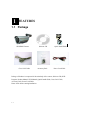
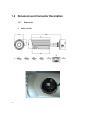
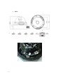
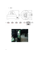
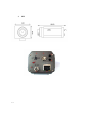
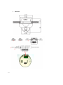
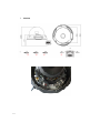
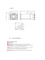
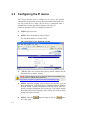
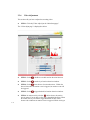
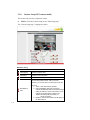
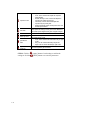
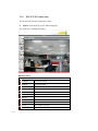
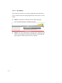
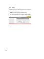
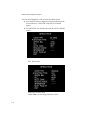
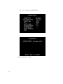
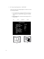
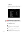
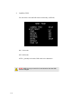
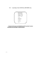
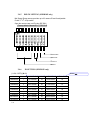
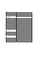
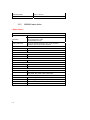
Speco Internet Protocol (SIP) Series
Camera Instruction Manual
(Version 1.0.0)
SIP Weatherproof Bullet Cameras
SIPB1 & SIPB2
SIP Tamperproof Weatherproof Dome Cameras
SIPD3 & SIPD4
SIP Traditional Camera
SIPT5
SIP Weathrproof Speed Dome Camera
SIPSD10X
SIP Megapixel Cameras
SIPMPB & SIPMPD & SIPMPT
i
Speco Technologies
200 New Hwy, Amityville, NY 11701
800-645-5516
www.specotech.com
Table of Contents
1.
FEATURES....................................................................................................... 1-1
1.1 Package ....................................................................................................................... 1-1
1.2 Dimension and Connector Description....................................................................... 1-2
2.
1.2.1
Dimensions ....................................................................................................................1-2
1.2.2
Connector Description ...................................................................................................1-9
INSTALLATION ............................................................................................ 2-11
2.1 Minimum System Requirements ........................................................................... 2-11
2.2 Preparation before setup ........................................................................................ 2-12
2.2.1
2.3
Configuring the IP device................................................................................... 2-17
2.3.1
Video Display ..............................................................................................................2-19
2.3.2
Host Setting .................................................................................................................2-21
2.3.3
WAN Setting ...............................................................................................................2-23
2.3.4
Date Setting .................................................................................................................2-26
2.3.5
Video Setting ...............................................................................................................2-28
2.3.6
Video Adjustment........................................................................................................2-31
2.3.7
Camera Setup...............................................................................................................2-33
2.3.8
Camera Setup (PTZ camera model).............................................................................2-35
2.3.9
PTZ (PT/TZ Camera only) ..........................................................................................2-37
2.3.10
User Account Management .........................................................................................2-39
2.3.11
System Info..................................................................................................................2-40
2.3.12
Firmware Upgrade.......................................................................................................2-42
2.3.13
Factory Default ............................................................................................................2-44
2.3.14
Save Reboot.................................................................................................................2-45
2.3.15
Logout..........................................................................................................................2-46
2.4
ii
Setup your PC network................................................................................................2-12
Use of OSD ........................................................................................................... 2-47
2.4.1
Function.......................................................................................................................2-47
2.4.2
OSD Menu Setting.......................................................................................................2-48
2.4.3
Operating Camera OSD Menu.....................................................................................2-49
2.4.4
Operating Camera OSD Menu (SIPSD10X) ...............................................................2-70
2.4.5
DIP SW SETTING (SIPSD10X).................................................................................2-88
2.4.6
ID SETTING (SIPSD10X) ..........................................................................................2-88
3.
2.4.7
PROTOCOL (SIPSD10X)...........................................................................................2-89
2.4.8
BAUD RATE SETTING (SIPSD10X)........................................................................2-89
APPENDIX ..................................................................................................... 3-90
3.1 Specification ............................................................................................................. 3-90
iii
3.1.1
SIP Camera Series .......................................................................................................3-90
3.1.2
SIPMP Camera Series .................................................................................................3-97
1
1.
1.1
FEATURES
Package
SIP/SIPMP Camera
Cross LAN Cable
Software CD
Accessory Pack
Quick Install Guide
Power Lead Cable
Package of Products is composed of the main body of the camera, Software CD (NVR
Program, Product Manual, NVR Manual), Quick Install Guide, Cross LAN Cable,
Accessory Pack, Power Lead Cable.
Please check before starting installation.
1-1
1.2
Dimension and Connector Description
1.2.1
1.
Dimensions
SIPB1 & SIPB2
①
②
③
④
⑤
⑥
⑦
⑧
1-2
2.
①
SIPD3
②
③
⑥
1-3
④
⑦
⑤
⑧
3.
①
SIPD4
②
③
④
⑦
⑧
⑥
1-4
⑤
4.
SIPT5
⑧
④
③
②
⑨
⑥
①
1-5
⑤
5.
SIPSD10X
②
③
⑤
④
①
⑩
⑥
1-6
6.
①
SIPMPB
②
③
⑥
1-7
⑤
⑪
7.
SIPMPD
①
②
③
⑤
⑥
1-8
8.
SIPMPT
②
⑫
⑤
③ ⑨
⑥
1.2.2
①
Connector Description
12 Volts DC Power Input
Audio Output
Audio Input : The SIP Camera supports one audio input and output
Video Output : The SIP Camera supports one analog video output with
BNC connector.(** Not available on the megapixel series)
⑤ Ethernet Port : Standard RJ45 connector. Supporting POE. (** Built-in
Power Over Ethernet except the SIPSD10X speed domes)
⑥ Reset Button (** Please open the case for the Bullet / Dome type camera )
①
②
③
④
1-9
Step 1 : Switch off SIP Camera by disconnecting the power cable.
Step 2 : Using a suitable pointed object, press and continue to hold the Reset
Button. While continuing to hold the reset button, reconnect the power cable.
Step 3 : Keep holding the reset button for 6 seconds, release the reset button.
The unit will start up with factory default settings.
⑦ Video test port : Second Video Test output
⑧ OSD control joystick
⑨ Action LED Indicator : The LED will light up after SIP Camera has
successfully completed the boot process.
⑩ DIP Switch (Baud rage & Address setting) :
Please refer to the 2.4.5 for more descriptions
⑪ LED Light level controller
⑫ Digital Input / Transistor Output
1-10
2
INSTALLATION
2.
2.1
Minimum System Requirements
CPU
Pentinum 4 2.4GHz and above
Hard Disk
40 GB or above
Memory
256 MB or above
Operating System
Windows XP with SP2 or above
Video Resolution
SVGA or XGA with 1024x768 resolution
2-11
2.2
Preparation before setup
To configure your IP device, you have to use Internet Explorer to log in.
Before that, your PC’s network settings and the IP device’s IP address must
be set up. Make sure all the connections are connected correctly, and then
follow the procedures below.
1.
Setup your PC network
You have to match your PC’s TCP/IP setting with the IP device’s
default settings before you can use IE browser to login it. This section
tells you how to setup your PC’s TCP/IP settings.
2.
Setup IP device’s IP address
This IP device’s IP address can be setup manually or automatically by
network service (DHCP). If it acquires the IP address by using the
DHCP service, please use the IP utility software bundled in the product
CD to search all the IP devices’ IP address.
2.2.1
Setup your PC network
To set up the network of IP device via a PC, you have to change the TCP/IP
settings of the PC.
The following are the default network settings of IP device.
IP Address: 192.168.0.100
Subnet Mask: 255.255.255.0
To access the IP device, the IP address of the PC should match the address
below.
IP Address: 192.168.0.xxx
Subnet Mask: 255.255.255.0
NOTE: xxx should be a number from 1 to 254, but 100 is excepted.
2-12
The procedure below is the setup procedure of a PC using Windows XP as
its OS. When running an OS other than Windows XP, please refer to the
manual included with the OS.
2-13
z
STEP 1
Start up your PC.
z
STEP 2
Click the [Start] and select the "Control Panel"
z
STEP 3
Double-click the "Network and Internet connections" icon.
z
STEP 4
Double-click the "Network connections" icon
2-14
z
STEP 5
Click “Local Area Connections”, and then click “Change settings of
this connection” in the network Task menu.
z
STEP 6
Click “Internet Protocol (TCP/IP)”, and then click the [Properties]
button.
2-15
z
STEP 7
Click the “Use the following IP address” radio button and enter the IP
address and the subnet mask.
Please set the settings as below.
IP address: 192.168. 0.xxx
Subnet mask: 255.255.255. 0
(NOTE: xxx should be a number
from 1 to 254, but 100 is
excepted.)
z
STEP 8
Click the [OK] button and the window dialog box closes.
2-16
2.3
Configuring the IP device
This section describes how to configure the IP device. The product
administrator has unlimited access to all setup windows and normal users
can only watch the live image. The IP device is configured under a
standard browser (Microsoft Internet Explorer 6.0 or above).
Follow the procedures below to configure the IP device.
z
STEP 1: Open a browser
z
STEP 2: Enter the IP address of the IP device.
The default IP address is “192.168.0.100”
The “Login Page” is now displayed as below.
z
STEP 3: Enter the Account name (factory default: Admin) and the
Password (factory default: 123456).
NOTE: Internet Explorer of 6.0 or above is highly recommended. If you
don’t have the it, please download it from
http://www.microsoft.com/windows/ie/downloads/default.mspx
2-17
z
STEP 4: Select the language of the IP device user interface. You can
select from English, Traditional Chinese, Simplified Chinese, Japanese,
Spanish, Italian, German, Portuguese,Czech and French. This user
interface setting will disappear once you log out, if you want to change
the default user interface language, please change the setting of [Host
setting] after login successed.
z
STEP 5: Click the
to re-enter again.
button to login or click the
button
Once successfully login, the “Video Display page” will be displayed
as below.
2-18
2.3.1
Video Display
This section tells you how to view live images via Internet Explorer.
z
STEP 1: Click the [Video Display] on the “Main Setup page”.
The “Video Display page” is displayed as below.
z
STEP 2: Check the
[MPEG4/MJPEG] to select the Compression
type. Once selected, the video server/IP camera will start to stream
with new compression type.
z
STEP 3: Click the
[Scale Down] checkbox to scale down the
SXGA(1280x1024)/720P(1280x720) to VGA resolution.
z
STEP 4: Check the
[Mute] checkbox to mute or display audio
from the video server/IP camera.
z
STEP 5: Click the
[Audio Out] checkbox to enable/disable audio
transmission from this PC to IP device’s audio out and change audio
out volume. Ex: while this function enabled you can talk to the people
at the IP device site.
2-19
z
STEP 6: Click the
[DO1] Button of trigger / dis-trigger DO
function by DO1.
z
STEP 7: Click the
[DO2] Button of trigger / dis-trigger DO
function by DO2.
z
STEP 8: Click the
Setup page”.
[Quit] to exit the live view and return to “Main
NOTE: If the streaming is disabled, you cannot see the live images
here.
NOTE: Be sure to set the Network Connections Type to Auto
Negotiation to respective apparatus connected to this IP device via
network. Otherwise, the maximum transmission performance might
not be achieved. This is because the IP device follows MII standard.
2-20
2.3.2
Host Setting
This section tells you how to setup IP device’s host settings and LAN
settings.
z
STEP 1: Click the [Host Setting] on the “Main Setup page”.
The “Host setting page” is displayed as below.
z
STEP 2: Configure these settings with reference to the table below. If you
are still unsure what to set, contact your system administrator.
■Host Setting
Parameters
Host name
Language
2-21
Description
Enter a host name, and this host name will be shown when you
use the IP utility or the SDK to search for the IP device.
Select the language of default user-interface. Each user login
will see the default user-interface first.
■Network link speed & duplex
Parameters
WAN port
Description
This item lets you select the network transmission speed of
WAN port. You can select from
1. Auto detect (default setting)
2. 100Mbps / Full duplex
3. 100Mbps / Half duplex
4. 10Mbps / Full duplex
5. 10Mbps / Half duplex
■Port Mapping
Parameters
TOS (type of
service)
TOS priority
Description
Select whether to add the TOS tag onto the streaming data.
Streaming data with a higher priority TOS tag will be transmitted
first while compared with other data to be transmitted.
Select the TOS tag’s priority to be added onto the streaming.
You can select between
1. Normal-Service
2. Minimize-Cost
3. Maximize-Reliability
4. Maximize-throughout
5. Minimize-Delay
■ToS (Type of Service)
Parameters
Description
HTTP port
Select the port for this IP device to use HTTP protocol.
Search server
port1
Search server
port2
Select the port1 for this IP device to support search function of
the application program (e.g. IP utility).
Select the port2 for this IP device to support search function of
the application program (e.g. IP utility).
z
STEP 3: Click the
[Apply] button of each setting to confirm the
settings or click the
[Reset] button to re-enter the parameters.
NOTE: Once finished all settings, be sure to click the [Save Reboot]
button, otherwise, some settings won’t take effect.
NOTE: Check with your system administrator, if Client PC and IP device
are setting in different VLANs, please connect to WAN port.
NOTE: Be sure to set the Network Connections Type to Auto
Negotiation to respective apparatus connected to this IP device via
network. Otherwise, the maximum transmission performance might not
be achieved. This is because the IP device follows MII standard.
2-22
2.3.3
WAN Setting
This section tells you how to setup IP device’s WAN, DNS server and
DDNS server settings.
z
STEP 1: Click the [WAN Setting] on the “Main Setup page”.
The “WAN setting page” is displayed as below
z
2-23
STEP 2: Configure these settings with reference to the table below. If
you are still unsure what to set, contact your system administrator.
■WAN Setting
Parameters
Dynamic IP
address
Description
Click this to enable IP device’s DHCP function.
It will acquire its WAN port IP address from a DHCP server
within the same network. (You must have a DHCP server in
order to enable this function.)
Click this to manually enter the IP device WAN port IP
address.
IP address: Enter the WAN port IP address.
Static IP
Subnet mask: Enter the subnet mask of WAN port. If
IP address is changed, adjust the subnet mask
accordingly.
address
ISP gateway: Enter the IP address of the gateway
(the router).
Click this when you connect IP device directly to the xDSL
modem.
User name: Enter the user name of your xDSL
account.
PPPoE
Password: Enter the password of your xDSL
account.
Note: You have to click the [Save Reboot] after you click the
[Apply button] to let this IP device start xDSL connections.
■DNS server Setting
Parameters
Primary DNS
server
Secondary DNS
server
Description
Defines the IP address of the primary DNS server. This is used
for identifying this computer by name instead of IP address.
The IP address of the secondary DNS server. It will be used
once the primary DNS server fails.
■DDNS server Setting
Parameters
DDNS type
Service ISP
Host name
2-24
Description
Click this to enable IP device’s DDNS function.
DDNS function enables user to connect to this IP device by
domain name even if its IP address is not static.
Click one of the DDNS service providers.
You can visit their website to get a DDNS service account for
this IP device.
Enter the host name of your DDNS service account. (ex:
xxxx.dyndns.org)
User name
Enter the user name to login your DDNS service account.
Password
Enter the password to login your DDNS service account.
z
STEP 3: Click the
settings or click the
[Apply] button of each setting to confirm the
[Reset] button to re-enter the parameters.
NOTE: Check with your system administrator, if Client PC and IP
device are setting in different VLANs, please connect to WAN port.
NOTE: Once finished all settings, be sure to click the [Save Reboot]
button, otherwise, some settings won’t take effect.
NOTE: Be sure to set the Network Connections Type to Auto
Negotiation to respective apparatus connected to this IP device via
network. Otherwise, the maximum transmission performance might not
be achieved. This is because the IP device follows MII standard.
2-25
2.3.4
Date Setting
This section tells you how to setup IP device’s date and time settings.
z
STEP 1: Click the [Date Setting] on the “Main Setup page”.
The “Date setting page” is displayed as below
z
STEP 2: Configure these settings with reference to the table below. If
you are still unsure what to set, contact your system administrator.
■Date Setting
Parameters
SNTP/NTP
server
Description
Click this to enable IP device’s SNTP/NTP function.
SNTP/NTP function enables this video to synchronize its time
settings with a SNTP/NTP server. You can use this function to
make sure all your IP devices’ time is the same. Additionally,
with our embedded digital-time-code in the streaming, you can
tell the event sequence accurately.
IP address: Enter the IP address of the SNTP/NTP
server.
Sync time: Select the time interval for this IP device
to synchronize its time.
Click this to manually setup the date & time.
Set manually
Date : Select the date
Time: Select the time
Time zone
Day Light Saving
2-26
Select the time zone offset for local settings
Select Type 1 to specify daylight saving time by week
number in a month; select Type 2 to specify daylight saving
time by date.
Start Time : Select the daylight savings start time.
End Time : Select the daylight savings end time.
z
STEP 3: Click the
[Apply] button of each setting to confirm the
settings or click the
[Reset] button to re-enter the parameters.
NOTE: Once finished all settings, be sure to click the [Save Reboot]
button, otherwise, some settings won’t take effect.
Manually set date and time will be gone, if power off.
2-27
2.3.5
Video Setting
This section tells you how to setup IP device’s video and streaming settings.
z
STEP 1:
Click the [Video Setting] on the “Main Setup page”.
The “Video setting page” is displayed as below
■Video setting
Parameters
Camera name
Description
The camera name is reserved for customer use.
Select the streaming mode.
1. TCP only
2. Multicast only
Streaming Method
3. RTP Over UDP
4. RTP Over Multicast
5. RTP Over UDP & Multicast
RTSP Authen
Checkbox to enable RTP streaming’s Account/Password
authentication.
Enable
2-28
RTP B2 Frame
Enable
Checkbox to enable the B2 frame in RTP streaming
Audio
Select enable or disable the audio function.
Input Sensitivity
Select HIGH or LOW of the audio input sensitivity
Multicast IP
Select the multicast IP. Default settings is 228.5.6.1
Multicast TTL
Select the multicast TTL. Default setting is 255.
IGMP
Select video type connected to the video-in of this IP
device. If you use an incorrect video type, some images
might be lost.
Resolution
Select the video resolution of the IP device.
Select the frame rate mode.
Constant: The streaming’s frame rate remains
constant at all conditions.
Frame rate mode
Variable: The streaming’s frame rate will variants
according to the images variability to keep the
image quality good.
Frame rate
Encoder Type
Video Bitrate
Mode
Video Maximum
Bitrate
Bitrate
Serial Port Baud
Rate
Select the frame rate of the video streaming.
Select the encoder’s compression type.
1. MPEG4
2. MJPEG
Select the video bitrate mode.
Constant Bit Rate: The streaming’s bitrate remains
constant at all conditions.
Variable Bit Rate: The streaming’s bitrate will
variants according to the images variability to keep the
image quality good.
Select the Maximum bitrate of the video straming.
Designating a limited bit rate may reduce frame
rate. Doing so will also disable Bit Rate setting below.
Select the bit rate of the video streaming. You can select
from 28Kbps to 3Mbps.
Note: Lower bit rate consumes less bandwidth but
delivers lower quality images.
High bit rate consumes more bandwidth but delivers
higher quality images.
Select the Baud Rate setting of serial port.
Serial Port Control Select the Control setting of serial port.
RTSP port
Select the port for this IP device to support RTSP
Video RTP Over
Multicast
Audio RTP Over
Multicast
Enable/disable the multicast video streaming via RTP
protocol
Enable/disable the multicast audio streaming via RTP
protocol
Select the port for this IP device to support video control
Video control port
function of the application program.
Video streaming Select the port for this IP device to support video
streaming function of the application program.
port (TCP Only)
Video multicast
Select the port for this IP device to support video multicast
function of the application program.
port (Multicast
2-29
Only)
STEP 3: Click the
settings or click the
2-30
[Apply] button of each setting to confirm the
[Reset] button to re-enter the parameters.
2.3.6
Video Adjustment
This section tells you how to adjust the streaming video.
z
STEP 1: Click the [Video Adjust] on the “Main Setup page”.
The “Video adjust page” is displayed as below
2-31
z
STEP 2: Set the
checkbox to enable motion detection function.
z
STEP 3: Set the
sensitivity of motion detection windows.
z
STEP 4: Set the
interval time of motion detection. . Within the
interval time after the motion event is triggered, no motion event will
be triggered.
z
STEP 5: Set the
z
STEP 6: In motion activity window
, the bar shows the motion
activity status. You can also see the trigger threshold (Red line). When
the motion activity exceeds the trigger threshold, the bar would
become red to indicates an motion event is triggered. While viewing at
trigger threshold of motion detection windows.
the motion activity window, you can adjust the motion sensitivity (for
more or less activities to be triggered) and the threshold (for how much
activity would trigger a motion event. If you are not sure, recommend
you to set
a. Sensitivity: 80, Threshold: 2~5
(for normal environment)
b. Sensitivity: 80, Threshold: 5~10 (for very noisy environment)
z
STEP 7: When satisfied with the motion settings, click the
[Apply]
z
STEP 8: Adjust the video by changing the value of
“Brightness”,
“Saturation” and
“Contrast”. See the images displayed above
for the effect of the current setting.
z
STEP 9: When satisfied with the video settings, click the
button of each setting to confirm the settings or click the
[Apply]
[Reset]
NOTE: Once finished all settings, be sure to click the [Save Reboot]
button, otherwise, some settings won’t take effect.
NOTE: You may find a support package for helping you on better
video quality adjustment. Please visit our web site, and get the
support document TS-00103.
2-32
2.3.7
Camera Setup
This section tells you how to adjust the camera.
z
STEP 1: Click the [Camera Setup] on the “Main Setup page”.
The “Camera Setup page” is displayed as below
■Camera setting
Parameters
Description
Video Flipping
Checkbox to flip the video.
Video Mirror
Checkbox to mirror the video.
Lens
Compensation
NightTime Gain
Threshold
Checkbox to load the best video setting for bundled lens.
Select the nighttime gain threshold.
Select the white balance mode. After you set the
White Balance
Mode
2-33
parameter, you need to wait for 5~10seconds to see the
final result.
1. AUTO : Auto white balance (default)
2. INDOOR1: Select the indoor white balance profile
1.
3. INDOOR2: Select the indoor white balance profile
2.
4. OUTDOOR1: Select the outdoor white balance
profile 1.
5. OUTDOOR2: Select the outdoor white balance
profile 2
6. HOLD CURRENT: Select this to let the IP
camera automatically obtain a best white balance
setting according to current environment. The IP
camera will use this setting to adjust color.
NOTE: This setting will be lost after you
reboot the camera.
7. MANUAL: Select this to enable manual setting of
the white balance. You will need to enter the R
Gain and B gain setting below.
R Gain
(Manual White balance
mode only)
B Gain
(Manual White balance
mode only)
Exposure mode
Exposure Gain
Shutter Speed
AGC Gain
(In auto Exposure
mode only)
Maximum Auto
Shutter Speed
(In auto Exposure
mode only)
Add or decrease blueness to the video when under
Manual White Balance mode. (This function is only
available in Manual White balance mode.)
Select exposure mode to auto or manual.
- Auto: The IP camera will adjust the exposure
automatically.
- Manual: (In Manual White balance mode only)
Manually select the Exposure Gain and Shutter
Speed below.
Select the exposure Gain of the IP camera. The higher the
value = brighter images.
Increase or decrease the shutter speed. The closer the
number is to 1, the better nighttime performance is,
although this also causes motion blur to the video.
When exposure mode is auto, IP camera will adjust its
shutter speed according to AGC gain and the Maximum
auto shutter speed. Higher AGC gain = brighter images.
When exposure mode is auto, IP camera will adjust its
shutter speed according to AGC gain and the Maximum
auto shutter speed. This setting is to set the maximum
shutter speed range of this camera.
Flickless Mode
Change settings between 60Hz or 50Hz, depending on
the AC power type of your region.
STEP 2: Click the
[Apply] button of each setting to confirm the
settings or click the
2-34
Add or decrease redness to the video when under Manual
White Balance mode. (This function is only available in
Manual White balance mode.)
[Reset] button to re-enter the parameters.
2.3.8
Camera Setup (PTZ camera model)
This section tells you how to adjust the camera.
z
STEP 1: Click the [Camera Setup] on the “Main Setup page”.
The “Camera Setup page” is displayed as below
■Camera setting
Parameters
Description
Video Flipping
Checkbox to flip the video.
Video Mirror
Checkbox to mirror the video.
BLC
Checkbox to enable/disable back light compensation.
Select the white balance mode. After you set the
parameter, you need to wait for 5~10seconds to see the
White Balance
Mode
2-35
final result.
1. AUTO : Auto white balance (default)
2. HOLD CURRENT: Select this to let the IP
camera automatically obtain a best white balance
setting according to current environment. The IP
camera will use this setting to adjust color.
NOTE: This setting will be lost after you
reboot the camera.
3. MANUAL: Select this to enable manual setting of
the white balance.
Exposure mode
AGC Gain
Auto IRIS Level
Select the Iris level.
Sense up Level
Select the sense up level.
Light Sensor
Mode
Select light sensor mode.
- Auto: The IP camera will auto switch day or night
mode.
- Day: The IP camera will always day mode.
- Night: The IP camera will always night mode.
NightTime Gain
Threshold
Select the nighttime gain threshold.
STEP 2: Click the
settings or click the
2-36
Select exposure mode.
- Auto: The IP camera will adjust the exposure
automatically.
- Shutter Priority: The IP camera will adjust the
exposure by shutter priority first.
- Iris Priority: The IP camera will adjust the
exposure by Iris priority first.
- Manual: Manually select the Exposure Gain and
Shutter Speed below.
When exposure mode is auto, IP camera will adjust its
shutter speed according to AGC gain and the Maximum
auto shutter speed. Higher AGC gain = brighter images.
[Apply] button of each setting to confirm the
[Reset] button to re-enter the parameters.
2.3.9
PTZ (PT/TZ Camera only)
This section tells you how to adjust the camera.
z
STEP 1: Click the [PTZ] on the “Main Setup page”.
The “PTZ page” is displayed as below
■Camera setting
Parameters
2-37
Description
Pan Speed
Select the pan speed.
Tilt Speed
Select the tilt speed.
Home
Click the button of go to home function.
Reset
Click the button of reset the pan/tilt/zoom function.
PT Control
Click the each button of pan and tilt control.
Zoom Speed
Select the zoom speed
Zoom In
Click the button of zoom in.
Zoom Out
Click the button of zoom out.
Auto Focus
Checkbox to enable/disable auto focus function.
Focus In
Click the button of focus in.
Focus Out
Click the button of focus out.
2-38
Auto Pan Enable
Checkbox to enable/disable auto pan function.
Entry
Select the preset number
Dwell
Setting the delay time of auto pan function.
State
Preset state of enable or disable.
Add Preset
Click the button of add preset number.
Del Preset
Click the button of del preset number.
2.3.10 User Account Management
This section tells you how to setup accounts.
z
STEP 1: Click the [User account] on the “Main Setup page”.
The “Account management page” is displayed as below
z
STEP 2: Setup the account names and their respective passwords.
There are 1 root (administrator) account and 10 common user
accounts. Administrator account allows the user to watch the live view
and setup everything; but common user account allows user only to
watch the live image.
z
STEP 3: Click the
settings or click the
[Apply] button of each setting to confirm the
[Reset] button to re-enter the parameters.
NOTE: Once finished all settings, be sure to click the [Save Reboot]
button, otherwise, some settings won’t take effect.
2-39
2.3.11 System Info
This section tells you how to see the system information of this IP device
including system information, WAN status and system log.
z
STEP 1: Click the [System info] on the “Main Setup page”.
The “System information page” is displayed as below
z
STEP 2: View the information at the 3 columns. This information is
very useful to understand the IP device status and to resolve any
problem that might occur.
■System info
Column
System info
WAN status
System log
2-40
Description
It shows the firmware version, MAC address, production ID, and
factory default type of IP device.
It shows the WAN port’s IP address, netmask, gateway, DNS
server, DDNS host and connection status.
It shows the system event. This column is very useful to as a
diagnostic tool.
z
STEP 3: Click
[Parameter List] where you may see all configurations
of the IP device.
z
2-41
STEP 4: Click
[Server Report] to export related information of the IP
device while reporting a support to your support channel.
2.3.12 Firmware Upgrade
This section tells you how to see update IP device’s firmware. You can
always visit our web site for the latest firmware.
z
STEP 1: Click the [Firmware] on the “Main Setup page”.
The “Firmware upgrade page-1” is displayed as below
z
STEP 2: Click
[Apply] button. The ‘’firmware upgrade page-2”
will be displayed as below.
■Date Setting
Parameters
Firmware
images file
2-42
Description
You can upload the firmware images here.
Click the [browse] to select the an image file and click the
[enter].
You can always get the latest version at our website.
MD5 file
z
z
You can upload the MD5 file here.
Click the [browse] to select an MD5 file and click the [enter].
You can always get the latest version at our website.
NOTE: The version of the firmware image and the MD5 file to be
uploaded must be the same, otherwise, the firmware upgrading will
fail and the IP device will continue using previous firmware version.
STEP 3: Click the
[Upload] button to start upgrading, or click the
[Reset] to re-select the files, or select
z
2-43
to cancel the process.
STEP 4: The upgrade process window shows a progress bar indicating
upgrade status. When the upgrading is completed, the system will
reboot.
2.3.13 Factory Default
This section tells you how to see load IP device’s factory default setting.
z
STEP 1: Click the [Factory Default] on the “Main Setup page”.
The “Factory default setting page” is displayed as below
2-44
z
STEP 2: Click the [Apply] button to go to loading confirmation page
or click the [Reset] button to exit to previous page.
z
STEP 3: A confirmation page will be displayed. Click the [Save
Reboot] button to start loading factory default settings.
2.3.14 Save Reboot
This section tells you how to save all the settings and reboot this IP device.
This is critical because some settings might not take effect before save and
reboot.
z
STEP 1: Click the [Save and reboot] on the “Main Setup page”.
The “Save and reboot page” is displayed as below.
z
2-45
STEP 2: The Action LED indicator will light down to indicate that the
IP device is rebooting. After around 30 seconds, the Action LED will
light up again to indicate that the reboot is completed.
2.3.15 Logout
This section tells you how to logout the IP device. Be sure to logout this IP
device once your setting is completed.
z
STEP 1: Click the [Logout] on the “Main Setup page”.
You will logout and return to the “Login Page” displayed as below.
2-46
2.4
OSD Setting
2.4.1
Function
Deleted: <sp>¶
2-47
2.4.2
OSD Menu Setting
When you control the OSD by using joystick on the camera, refer to the
following (select models only)
UP
R
L
I
G
E
F
H
T
T
DOWN
When you control by the five keys on the NVR Software GUI refer to the
following
2-48
SETUP
2.4.3
z
Operating Camera OSD Menu
STEP 1: Press the Set button to access the SETUP mode.
SETUP menu is displayed on the monitor screen.
z
STEP 2: Select the desired feature using the UP or DOWN button.
Each time you press the UP or DOWN button, the arrow indicator
moves up or down.
Move the arrow indicator to the desired feature item.
z
STEP 3: Change the status of the selected feature using the LEFT or
RIGHT button.
If you press RIGHT or LEFT button, it appears available status.
Press the button when gets desired feature.
z
STEP 4: When competed, move the arrow indicator to ‘EXIT’ and
press the SET button.
NOTE: You can access submenu using SET button.
For the mode with ‘---‘, you may net access submenu.
2-49
1.
Setting up the LENS
Select the lens pressing the RIGHT button.
a. On the SETUP menu screen, move the arrow indicator to the
lens using the up or Down button.
b. Select the desired feature using the LEFT or RIGHT button.
2-50
When DC LENS selected, press SET button to control the
BRIGHTNESS.
2-51
Shutter status and speed control
You can control brightness of the screen by the shutter speed.
a. Press the SET button to display the setup menu and move the
arrow indicator to ‘SHUTTER’ using the UP or DOWN
button.
b. Set ‘SHUTTER’ the desired mode using the LEFT or RIGHT
button.
OFF : Deactivation
FLK(1/100) : Flicker mode
(When WDR is on, the image can flicker a little)
2-52
Manual : When setting shutter speed manually.
(Only for LENS mode)
You can select speed from ‘1/60’ to ‘1/200,000’
2-53
ESC : You can control the BRIGHTNESS.
c. When completed, press ‘SET’
2-54
2.
SLC ( Speco Light Compensation ) – BACKLIGHT
A built-in SR chip provides intelligent light level control to overcome
serve Backlight conditions.
a. Press the SET button to display the SETUP menu and move
arrow indicator to ‘BACKLIGHT’ using the UP or DOWN
button.
b. SET ‘BACKLIGHT’ to the desired mode using the LEFT or
RIGHT button.
OFF
2-55
/
LOW
/
MIDDLE
/
HIGH
AUTO GAIN CONTROL (AGC)
AGC is to get bright picture. Higher GAIN level, getting brighter
screen. However, you can get noise increase.
a. Press the SET button to display the SETUP menu and move
arrow indicator to ‘AGC’ using the UP or DOWN button.
b. SET ‘AGC’ to the desired mode using the LEFT or RIGHT
button.
OFF
2-56
/
ON
3.
WHITE BALANCE (WITE BAL.)
For color control on the screen, use ‘WHITE BALANCE’ function.
a. Press the SET button to display the SETUP menu and move
arrow indicator to ‘WHITE BALANCE’ using the UP or
DOWN button.
b. SET ‘WHITE BALANCE’ to the desired mode using the LEFT
or RIGHT button.
ATW (Auto Tracking White Balance)
: When color temperature is 2400 ~ 12000K, select this mode.
(Ex. A fluorescent lamp, outdoor)
AWC (Auto White Balance Control)
: The white balance is automatically adjusted in a specific
environment. In order to obtain the best result, press the set
button while the camera focuses on white paper. If the
environment including the light source is changed, you have
to adjust the white balance again.
Manual : To fine adjust, select the Manual mode. You can
increase or decrease the red or blue factor while monitoring
the difference on the screen. Set to ‘Manual, mode and press
2-57
the SET button. Increase or decrease the value for
RED(R-Gain) and BLUE(B-Gain), watching the color of the
picture, and press the SET button when you obtain the best
color.
NOTE: Proper White Balance may not be obtained under the
following conditions in these cases select the AWC mode.
When the scene contains mostly high color temperature object, such
as a blue sky or sunset.
When the scene is dim.
If your camera faces fluorescent lamp directly or is installed in the
place of the changing illumination.
2-58
4.
Digital Noise Reduction (Dynamic Noise Reduction)
DNR is to reduce the noise on the screen.
a. Press the SET button to display the SETUP menu and move
arrow indicator to ‘DNR’ using the UP or DOWN button.
b. SET ‘DNR’ to the desired mode using the LEFT or RIGHT
button.
OFF : Deactivation
LOW : Low reduction of the noise
MIDDLE : Middle reduction of the noise
HIGH : High reduction of the noise
NOTE: If you change the ‘GAIN’ menu from AGC-L to AGC-H
sensitivity is increased as well as noise on the screen.
When selected ‘GAIN’ menu OFF, DNR will not work.
2-59
5.
INTENSIFIER
Allows you to get clear images with function under night or low light
conditions
a. Press the SET button to display the SETUP menu and move
arrow indicator to ‘INTENSIFIER’ using the UP or DOWN
button.
b. SET ‘INTENSIFIER’ to the desired mode using the LEFT or
RIGHT button.
AUTO : When your camera is under night or low-lighting
level, select this mode.
NOTE: If you press SETUP at ‘AUTO’ menu from AGC-L to AGC-H
sensitivity is increased as well as noise on the screen.
When selected ‘GAIN’ menu OFF, DNR will not work.
2-60
6.
NEXT PAGE
a. Press the SET button to display the SETUP menu and move
arrow indicator to ‘NEXT PAGE’ using the UP or DOWN
button.
b. SET ‘NEXT PAGE’ to the desired mode using the LEFT or
RIGHT button.
2-61
CAMERA TITLE
a. Press the SET button to display the SETUP menu and move
arrow indicator to ‘CAMERA TITLE’ using the UP or DOWN
button.
b. SET ‘ON’ using the LEFT or RIGHT button.
NOTE: If the CAMERA ID feature is set to ‘OFF’, the name will not
displayed in the monitor.
c. Press the SET button to access tie SETUP mode.
d. You cam enter up to 15 characters.
① Move the cursor to character-enter location by using the
LEFT or RIGT button.
② Select the desired character by using the UP or DOWN
button.
③ Press Set button to confirm the blinking character. The first
character is saved and the cursor in the bottom of the screen
moves to the next position.
④ Repeat steps a,b and c until you create the foull name you
want.
2-62
⑤ Select the position at which the CAMERA TITKE will b
located on the screen.
NOTE: If the CAMERA feature is set to ‘OFF’, the name will not
displayed in the monitor.
After erasing the character from right to left, correct the character
again.
2-63
7.
CAMERA TITLE
You can choose color and B/W mode electronically. (OPTION)
ON : Color mode
OFF : B/W mode
AUTO : generally color mode, B/W mode in low luminance.
NOTE: OSD Key may not work for 3 seconds when the color B/W
mode is changed.
2-64
8.
SYNC
Two SYNCHRONIZATION modes are available… INTERNAL and
EXTERNAL LINE-LOCK. In LINE_LOCK mode, the camera sync to
the 60HZ phase.
a. Press the SET button to display the SETUP menu and move
arrow indicator to ‘SYNC’ using the UP or DOWN button.
b. SET to the desired mode using the LEFT or RIGHT button.
INT : Internal synchronization
L/L : if you choose ‘L/L’, you can adjust the desired phase.
- Press the SET button.
- You can adjust the desired phase from 0 to 270.
NOTE: Line Lock is only available in the 24-volt AC mode of
operation.
In 12volts DC, the SYNC menu is always in the ‘ INTERNAL'; mode.
2-65
9.
PRIVACY
To mask an area that you want to be private.
a. Press the SET button to display the SETUP menu and move
arrow indicator to ‘PRIVACY’ using the UP or DOWN button.
b. SET ‘PRIVACY’ to the desired mode using the LEFT or
RIGHT button.
OFF : Deactivation
ON : PRIVACY mode activated
- Press the SET button.
- Move the arrow indicator to area you want to mask.
- Set ‘ON’ using LEFT or RIGHT button.
- Press the SET button and then set the area’ bounds with the
method like MOTIN DET. Set
2-66
10. REVERSE
a. Press the SET button to display the SETUP menu and move
arrow indicator to ‘REVERSE’ using the UP or DOWN button.
b. SET ‘REVERSE’ to the desired mode using the LEFT or
RIGHT button.
OFF : Deactivation
ON : Make a reverse turn to RIGHT or LEFT.
2-67
11. DETAIL
a. Press the SET button to display the SETUP menu and move
arrow indicator to ‘DETAIL’ using the UP or DOWN button.
b. SET ‘DETAIL’ to the desired mode using the LEFT or
RIGHT button.
OFF : Deactivation
2-68
ON : DETAIL control mode (level 0~31)
When the level is up, the sharpness will increase.
Control this level to get your best picture quality.
If the level is too high, you can get an unnatural image with
video noise.
12. DEFAULT
Use to reset your camera to FACTORY DEFAULT SETTING.
13. PAGE1
PAGE 1 : Save the setting of NEXT PAGE function, and then
2-69
2.4.4
Operating Camera OSD Menu (SIPSD10X only)
MAIN MENU
DOME SETUP
CAMERA SET
AUTO SCAN
TOUR
PRAVACY
PATTERN
ALARM
SECTOR
EXIT
* Use the the five keys on the WebViewer GUI “up down” to move
the position and “left right” to make selection
2-70
A. Dome Setup
To enter Dome setup, use the five keys right to move when cursor on
dome setup.
DOME SET
CAMERA ID
:
CAM1□□□□□□□□□□□□
RECOVER
: OFF
MANUAL SPEED
: 100°/S
AUTO FLIP
: OFF
ZOOM SPEED
: FAST
ALARM
: DISABLE
LANGUAGE : ENGLISH
[NEXT PAGE]
SAVE AND EXIT
EXIT
DEFAULT SETTING
A-1. DOME SET - CAMERA ID
To set camera ID, select up to 16 characters using five keys to the left or
right.
Press ZOOM TELE button to move to the next character from left to right
direction and
ZOOM WIDE button to move to the next character from right to left
direction (Space displays when appears)
A-2. DOME SET - RECOVER
This feature allows the dome to work from the last setting before you use
the dome manually
(Auto scan, group tour, preset, pattern or sectors) , after the set time,
even power shut down and it turns on again.
Recover time can be
programmed from 15 second to 99 seconds. The default setting is OFF.
A-3.
DOME SET - MANUAL SPEED
Manual Speed of Pan/Tilt is selectable from 100°/sec up to 150°/sec.
The default setting is 100°/sec
A-4.
DOME SET - AUTO FLIP
Auto Flip is available and the default setting is OFF.
2-71
Move five keys
“right or left” to select ON or OFF. The default setting is OFF.
A-5.
DOME SET – ZOOM SPEED
Zoom speeds are selectable FAST or SLOW mode.
the right direction for selecting FAST or SLOW.
FAST.
A-6.
Move five keys to
The default setting is
DOME SET – ALARM
All alarms are available after set as ENABLE Mode.
Move five keys to
right or left direction for selecting ENABLE/DISABLE. The default setting
is DISABLE.
A-7.
DOME SET – LANGUAGE
Multiple languages are selectable here including English, Italian and
Polish. Move five keys to the right or left direction to select language.
The default setting is ENGLISH.
A-8.
DOME SET – [NEXT PAGE]
DOME SET
SYSTEM LOCK: : OFF
[PASS WORD]
[OSD DISPLAY]
[SYSTEM STATUS]
[INITIALIZATION]
[PREVIOUS PAGE]
DEFAULT SETTING
A-8-1. DOME SET – [NEXT PAGE] – SYSTEM LOCK
Password protection provides keeping memorized data. It cannot be
adjusted by anybody without password. In order to enter [PASS WORD]
page, system lock status is must set as ON. Move five keys to right or left
direction to select ON. The default setting is OFF.
A-8-2. DOME SET – [NEXT PAGE] – [PASSWORD]
To enter this page to set a password, move five keys to the right direction.
The password must be set by preset number from 001 to 255 (Default
99)
2-72
The default setting is BLANK.
ENTER PASSWORD
BY ENTERING PRESET CODE
PASSWORD ***
CONFIRM ***
Press any number from 001~255 with preset button on password blank
and again it on confirm blank. Then “CONFIRMED” is displayed on the
monitor and the menu will go back to the previous page automatically.
ENTER PASSWORD
BY ENTERING PRESET CODE
PASSWORD ***
CONFIRM ***CONFIRMED
<CONFIRMED>
ENTER PASSWORD
BY ENTERING PRESET CODE
PASSWORD ***
CONFIRM ***CANCELLED
<CANCELLED>
If user presses wrong preset number between PASSWORD and
CONFIRM, “CANCELLED” is displayed on the monitor and if user failed 3
times, the menu will return to the previous page automatically * After
setting a Password, an operator must press memorized password in
order to enter OSD MAIN MENU, or to change the data which is
memorized originally.
* An operator must remember the password for the operation.
Manufacturer does not provide a memorized password.
A-8-3. DOME SET – [NEXT PAGE] – [OSD DISPLAY]
OSD ID displayed after set ON in here and it can be hiding if selected
OFF. Move five keys to the right or left direction in order to select
OFF/ON when the cursor is located each item.
2-73
OSD DISPLAY
CAMERA ID : OFF
PRESET ID : OFF
SECTOR ID : OFF
COORDINATE: ON
[PREVIOUS PAGE]
A-8-4.
DEFAULT SETTING
DOME SET – [NEXT PAGE] – [SYSTEM STATUS]
This page shows the information of this camera.
SYSTEM STATUS
PROTOCOL : PELCO D, P
BAUD RATE : 2400 BPS
FIRMWARE VER. : 2.00
UPGRADED DATE : 06.07,22
CAMERA MODULE : SDM100
[PREVIOUS PAGE]
DEFAULT SETTING
- Protocol and baud rate are shown according to the dip switch setting
(Refer to page 29, 30 and 31)
- Firmware version and upgraded date will be changed if upgraded.
- Below camera modules can be set as follows.
SDM100 : SAMSUNG 10X ZOOM CAMERA MODULE.
EN300 : OPTICAL 3X MODULE (PAN FOCUS)
: Board Camera ( with Fixed Lens)
A-8-5. DOME SET – [NEXT PAGE] – [INITIALIZATION]
To clear all memorized data for tour, preset, sector, privacy or pattern,
move five keys to the right direction when the cursor is on
[INITIALIZATION]
2-74
INITIALIZATION
[TOUR CLEAR]
[PRESET CLEAR]
[SECTOR CLEAR]
[PRIVACY CLEAR]
[PATTERN CLEAR]
[LOAD OPTIMIZED
DEFAULT]
[PREVIOUS PAGE]
- To clear memorize any data, move five keys to the right direction when
cursor is on each item.
TOUR CLEAR
TOUR CLEAR
ARE YOU SURE? YES NO
Press FOCUS NEAR button when the cursor is at YES in order to clear
memorized data. Then flickered each item such as tour, preset, sector
and so on is displayed on the monitor about 2~3 seconds. After this
process, the menu is returned to the previous page.
* [PRESET CLEAR], [SECTOR CLEAR], [PRIVACY CLEAR], [PATTERN
CLEAR] are same as [TOUR CLEAR].
LOAD OPTIMIZED DEFAULT
ALL DATA INITIALIZING
ARE YOU SURE? YES NO
- To clear all data and wants returning to factory default, move five keys
to the right direction when cursor is at [LOAD OPTIMIZED DEFAULT] to
enter the above page.
- Move five keys to the right or left direction in order to select YES, press
FOCUS NEAR button.
- Then “ALL DATA INITIALIZING” is displayed about 5~7 seconds and
then the menu is returned to the previous page automatically.
2-75
A-9.
DOME SET – [NEXT PAGE] – SAVE AND EXIT
To saving the memorized data and escape this page, move five keys to
the right direction when cursor is at SAVE AND EXIT.
A-10.
DOME SET – [NEXT PAGE] – EXIT
In order not to save any data and wants to escape this page, move five
keys to the right direction when cursor is at EXIT
B. CAMERA SET
CAMERA SET
FLICKER
: OFF
MIRROR : OFF
APERTURE : 10
D ZOOM : OFF
WB MODE
: AWB MODE
PIC FLIP : OFF
BLC : OFF
D/N MODE : AUTO
DSS MODE : OFF
EXIT
<TS-PTZ10X>
CAMERA SET
FLICKER
BLC
: OFF
EXIT
: OFF
< TS-PTZ3X >
B-1.
CAMERA SET - FLICKERLESS
Flickerless feature is selected between 50Hz and 60Hz. The default
setting is OFF (NTSC: 60Hz / PAL: 50Hz). Set flicker mode ON when
power source is in discord with frequency. The default setting is OFF
B-2.
CAMERA SET - MIRROR
This feature shows left and right exchanged picture image like mirror.
The default setting is OFF.
(10X Zoom)
B-3.
CAMERA SET – APERTURE
Aperture enhances picture details by increasing gain of the caemra and
2-76
sharpens the edges in the picture.
The default seeting is 10. (the
aperture level is from 01 ~ 15)
(10X Zoom)
B-4.
CAMERA SET – D ZOOM
Move five keys to the right direction in order to set as ON, if Digital Zoom
is necessary at install field. The default setting is OFF.
(10X Zoom)
B-5.
CAMERA SET – WB MODE
White balance functions have 4 modes according to the condition of
exterior lighting. The default setting is AWB and it may change the mode
option accoding to the lighting conditions as below.
AWB Mode – 3,200°K to 6, 000°K (10X Zoom)
z
z
z
B-6.
Indoor – up to 3,200°K
Outdoor – up to 5,800°K
ATW Mode - 2,000°K to 10, 000°K
CAMERA SET – PIC FLIP
Picture flip feature provides the top and down exchanged picture image
horizontally. Move five keys to the right or left direction to select OFF/ON.
The default setting is OFF.
(10X Zoom)
B-7. CAMERA SET – BLC (Back Light Compensation)
The default setting is OFF and BLC modes can be OFF/ON.
OFF – Backlight compensation is not activated.
ON – Back light compensation is activated.
B-8. CAMERA SET – D/N MODE
ICR filter is changeable according to the lighting, AUTO – NIGHT
MODE – DAY MODE.
The default setting is AUTO MODE.
(10X Zoom)
B-9. CAMERA SET – DSS MODE (DIGITAL SLOW SHUTTER)
2-77
If DSS turns on, digital slow shutter is working. Per second, the electronic
shutter will remain open to receive some more lighting.
(10X Zoom)
B-10. CAMERA SET – EXIT
To escape this page, move five keys to the right direction.
C. PRESET SET
To enter PRESET SET, move five keys to the right direction.
PRESET SET
PRESET NO :001
PRESET
ID :PRESET001------PAN :XXX.XX TILT : XXX.XX
SAVE
EXIT
C-1.
DEFAULT SETTING
PRESET – PRESET NO.
Up to 165 numbers of preset positions are available.
the right or left direction to select preset no.
C-2.
Move five keys to
PRESET – PRESET ID
To set preset ID, select up to 16 characters using Five keys to the left or
right.
Press ZOOM TELE button moves to the next character from the left to
the right direction and ZOOM WIDE button moves to the next character
from the right to left direction
(Space displays when appears)
C-3.
2-78
PRESET – PAN: XXX.X TILT: XX.X
Press FOCUS FAR button in order to set preset position then, use the
five keys to the position where memorized preset no. is needed. Then
press FOCUS FAR button again after setting a preset location.
C-4.
PRESET – SAVE
Move five keys to the right direction when the cursor is at SAVE and then
the cursor will be located on Preset ID for the continuous preset No.
setting.
C-5.
PRESET – EXIT
To escape this page, move five keys to the right direction.
D. AUTO SCAN SET
AUTO SCAN SET
START ANGLE : XXX.X.XX.X
END ANGLE : XXX.X.XX.X
DIRECTION : CW
ENDLES
: OFF
SPEED
: 10°/S
DWELL TIME: 03
SAVE AND EXIT
EXIT
D-1.
DEFAULT SETTING
AUTO SCAN- START ANGLE
To set start angle, press FOCUS FAR button then move five keys to the
starting angle which is needed memorized.
To press FOCUS FAR
button again is to escape.
D-2.
AUTO SCAN- END ANGLE
To set end angle, press FOCUS FAR button then move five keys to the
starting angle which is needed memorized.
To press FOCUS FAR
button again is to escape.
D-3.
2-79
AUTO SCAN – DIRECTION
Auto Scan directions are available with two direction as CW or CCW by
five keys to the right or left direction
CW: Clock wise direction (Default)
CCW: Count Clock Wise Direction.
D-4.
AUTO SCAN – ENDLESS
Auto Scan can use endless rotation, move five keys to the right direction
in order to select ON. Otherwise, the default setting is OFF.
D-5.
AUTO SCAN – SPEED
User can use auto scan speed from 05°/S up to 35°/S and the default
setting is 10°/S
D-6.
AUTO SCAN – DWELL TIME
To select dwell time, move five keys to the left or right direction in order to
adjust dwell time. Possible to set from 01 second to 30 seconds and the
default setting is 03 seconds.
D-7.
AUTO SCAN – SAVE AND EXIT
To saving the memorized data and escape this page, move five keys to
the right direction when cursor is at SAVE AND EXIT.
D-8.
2-80
AUTO SCAN – EXIT
To escape this page, move five keys to the right direction.
E. TOUR SET
8 Programmable tours can be set and each tour is available to set up to 64
preset steps.
TOUR SET
TOUR NO
: 01
TOUR TITLE :
TOUR01□□□□□□□□□□
TOUR STEP
: 01
PRESET NO. : 01
DWELL TIME : 03
SPEED
: 200°/S
SAVE
EXIT
DEFAULT SETTING
E-1. TOUR SET – TOUR NO.
Max.
8 group tour no. set by the five keys are available.
E-2. TOUR SET – TOUR TITLE
To set tour title, select up to 16 characters using Five keys to left or
right.
Press ZOOM TELE button to move the next character from the left to the
right direction and ZOOM WIDE button to move the next character from
the right to left direction (Space displays when appears)
Tour title is
not displayed on the monitor, but only for the reference of user.
E-3. TOUR SET – TOUR STEP
Each tour group consists of up to 60 preset steps with different dwell
time and speed. It is possible to match any preset # for each tour step.
E-4. TOUR SET – PRESET NO.
The decided tour step #1 ~64, it is possible to select any preset no. up to
64. The default setting is BLK
E-5.
2-81
TOUR SET – DWELL TIME
Dwell time provides up to 99 seconds from 01 second.
The default
setting is 03 seconds.
E-6. TOUR SET – SPEED
Each tour step can be set with different tour speed up to 200°/S and it is
selectable from 10°/S. Move five keys to the right or left direction to
select tour speed. The default setting is 200°/S.
E-7. TOUR SET – SAVE
To save the memorized data and escape this page, move five keys to the
right direction when cursor is at SAVE
E-8.
TOUR SET – EXIT
To escape this page, move five keys to the right direction
F. PRIVACY SET
Privacy function is provided by (10X Zoom) only.
4 Privacy masking zones are available to block out areas of security.
PRIVACY SET
PRIVACY NO: 01
DISPLAY
: OFF
ACTION
: MOVE
SAVE
EXIT
DEFAULT SETTING
F-1. PRIVACY SET – PRIVACY NO.
Up to 4 privacy masking zones are available.
F-2. PRIVACY SET – DISPLAY
Move five keys to the right or left direction to set ON in order to show the
selectable block in the center of the monitor. This block appears as a
translucent square with blue color after set ON. The default setting is
OFF.
2-82
F-3.
PRIVACY SET – ACTION(MOVE/ADJUST)
To set the blocking area, press FOCUS FAR button when the MOVE
MODE is appeared. Then use the five keys to the user defined area in
order to set blocking area. Then press FOCUS FAR button again to
escape from MOVE MODE.
To adjust size of blocking area, move five keys to the right or left direction
when the cursor is on ACTION. After move mode changed to ADJUST
MODE, press FOCUS FAR button in order to adjust the size of blocking
area. The size of blocking area can be adjustable by using five keys up
down or left right,. After adjusting size of blocking area, press FOCUS
FAR button to escape ADJUST mode.
z
ADJUST: You can change the masking size by using five keys to the
left or right direction
z
MOVE: You can move the masking area by using five keys to the left
or right direction (Default)
F-4. PRIVACY SET – SAVE
After setting the privacy masking zone, to save the data, move five keys
to the right direction when the cursor is on SAVE. After saving the data,
the cursor moves to PRIVACY NO.2 automatically to prepare the next
privacy masking zone.
F-5.
PRIVACY SET – EXIT
To escape this page, move five keys to the right direction
G. PATTERN SET
8 programmable patterns are available with 16 characters of title.
PATTERN SET
PATT NO
: 01
PATT TITLE: PATTERN01□□□□□□□
DATA FILL : 100%
SAVE
EXIT
2-83
DEFAULT SETTING
G-1. PATTERN SET – PATT NO.
Up to 8 programmable user-defined patterns set by the five keys on the
Webviewer GUI are available.
G-2. PATTERN SET – PATT TITLE
To set PATTERN TITLE, select up to 16 characters using Five keys to
the left or right.
Press ZOOM TELE button moves to the next character from the left to
the right direction and ZOOM WIDE button moves to the next character
from the right to left direction (Space displays when appears)
Pattern
title is not displayed on the monitor, but only for the reference of user.
G-3. PATTERN SET – DATA FILL
To fill the programming data, press FOCUS FAR button in order to start
the data fill up. Filling data is programmed according to the the five keys on
the Webviewer GUI movement. Press FOCUS FAR button again in order
to escape.
G-4. PATTERN SET – SAVE
To saving the filling data, move five keys to the right direction when the
cursor is on SAVE. Then the cursor moves to the PATT NO.02 in order to
prepare next pattern no.
G-5. PATTERN SET – EXIT
To escape this page, move five keys to the right direction
2-84
H. ALARM SET
4 Alarm inputs are available and each alarm is activating to presets, group
tours or patterns.
ALARM SET
ALARM NO
: 01
ALARM INPUT: OFF
ALARM ACT : 001
SAVE
EXIT
H-1.
DEFAULT SETTING
ALARAM SET – ALARM NO.
Up to 4 alarms are selectable by using five keys to the right direction
when cursor is on ALARM NO.
H-2.
ALARAM SET – ALARM INPUT
Input alarm ways provide two different ways as NC (Normal Close) or NO
(Normal Close)
The default setting is OFF
H-3.
ALARAM SET – ALARM ACT
Alarm activates various surveillance modes with Preset number up to 165,
Group tour up to 8, Pattern up to 8. Move five keys to the right or left
direction to select any preset number, group tour no. or pattern no.
H-4.
ALARAM SET – SAVE
After setting the alarm input ways and activation, to save the data, move
five keys to the right direction when the cursor is on SAVE. After saving
the data, the cursor moves to Alarm NO.2 automatically to prepare the
next alarm.
H-5.
ALARAM SET – EXIT
To escape this page, move five keys to the right direction
* Before activating Alarm, user must set ALARM ENABLE at DOME
SET – ALARM – ENABLE (Refer to page 15)
2-85
I. SECTOR SET
Up to 8 programmable sectors are available with 16 characters.
This feature is useful to memory the certain location such as parking zone
or so on.
When camera goes through this area, it shows the letter you memorized.
SECTOR SET
SECTOR
SECTOR
SECTOR
SECTOR
SAVE
EXIT
Start Position
NO
: 01
ID : SECTOR01□□□□□□□□
START: XXX.X.XX.X
END
: XXX.X.XX.X
End Position
DEFAULT SETTING
I-1. SECTOR SET – SECTOR NO.
Up to 8 programmable sectors set by the five keys are available.
I-2. SECTOR SET – SECTOR ID
set SECTOR ID, select up to 16 characters by using five keys to the left
or right.
Press ZOOM TELE button to move to the next character from the left to
the right direction and ZOOM WIDE button to move to the next character
from the right to left direction (Space displays when appears)
I-3. SECTOR SET – SECTOR START
To set SECTOR START angle, press FOCUS FAR button then move five
keys to the left or right direction to set the position. To press FOCUS
FAR button again is to escape.
I-4. SECTOR SET – SECTOR END
To set SECTOR END angle, press FOCUS FAR button then move five
keys to the left or right direction to set the position. To press FOCUS FAR
button again is to escape.
2-86
I-5. SECTOR SET – SAVE
After setting the SECTOR position, to save the data, move five keys to
the right direction when the cursor is on SAVE. After saving the data, the
cursor moves to SECTOR NO.2 automatically to prepare the next
SECTOR.
I-6. SECTOR SET – EXIT
To escape this page, move five keys to the right direction
J. EXIT
To escape OSD Main Menu, move five keys to the right or left direction
then this camera is ready to operate.
2-87
2.4.5
DIP SW SETTING (SIPSD10X only)
Mini Speed Dome camera provides up to 63 camera ID and it’s adjustable
ID with 1st~6th of Dip switch
Open the camera case, set ID using DIP SW1.
* Factory default: Camera ID = 1, PELCO-D
Termination
Baud rate
Protocol
ID Set
2.4.6
ID SETTING (SIPSD10X only)
(1-ON, 0-OFF)(1Î10)
DIP SW
ID VALUE
Deleted: <sp>
DIP SW
ID VALUE
DIP SW
ID VALUE
100000XXXX
1
111010XXXX
23
101101XXXX
45
010000XXXX
2
000110XXXX
24
011101XXXX
46
110000XXXX
3
100110XXXX
25
111101XXXX
47
001000XXXX
4
010110XXXX
26
100011XXXX
48
101000XXXX
5
110110XXXX
27
100011XXXX
49
011000XXXX
6
001110XXXX
28
010011XXXX
50
111000XXXX
7
101110XXXX
29
110011XXXX
51
000100XXXX
8
011110XXXX
30
001011XXXX
52
100100XXXX
9
111110XXXX
31
101011XXXX
53
2-88
010100XXXX
10
000001XXXX
32
011011XXXX
54
110100XXXX
11
100001XXXX
33
111011XXXX
55
001100XXXX
12
010001XXXX
34
000111XXXX
56
101100XXXX
13
110001XXXX
35
100111XXXX
57
011100XXXX
14
001001XXXX
36
010111XXXX
58
111100XXXX
15
101001XXXX
37
110111XXXX
59
000010XXXX
16
011001XXXX
38
001111XXXX
60
100010XXXX
17
111001XXXX
39
101111XXXX
61
010010XXXX
18
000101XXXX
40
011111XXXX
62
110010XXXX
19
100101XXXX
41
111111XXXX
63
001010XXXX
20
010101XXXX
42
101010XXXX
21
110101XXXX
43
011010XXXX
22
001101XXXX
44
2.4.7
PROTOCOL (SIPSD10X only)
7th~8th dip switches are used for Protocol Setting.
Factory Default: Pelco-D or Pelco-P ( Auto detection)
DIP SW1- 7
DIP SW1- 8
OFF
OFF
2.4.8
Pelco-D or Pelco-P
BAUD RATE SETTING (SIPSD10X only)
The 9th Dip Switch is used for BAUD RATE setting.
DIP SW can be changeable to 2400bps, 9600bps.
Factory Default: 9600bps.
DIP SW1
2-89
9th
BAUD RATE
OFF
2400
ON
9600
3 APPENDIX
3.
3.1
Specification
3.1.1
SIP Camera Series
* Network Spec.
Video Compression
Compression
Resolution
Bit Rate
Image Framge Rate
Audio Input
Compression
Audio Line Input
Audio Output
Compression
Audio Line Output
External I/O
Reset Button
Joystick
Network
Ethernet
Protocol
Software
Web Browser
Security
Compatibility
NVR Software
3-90
MPEG-4 SP
Full D1 (720x480 in NTSC, 720x576 in PAL)
VGA (640x480 inNTSC, 640x480 in PAL)
CIF (352 x 240 in NTSC, 352x288 in PAL)
QCIF (176x120 in NTSC, 176x144 in PAL)
28 K ~ 3 M bps
30 fps at full D1 resolution (NTSC)
25 fps at full D1 resolution (PAL)
8kHz, Mono, PCM
Unbalanced, 1.4 Vp-p 1Vrms, terminal Block
8kHz, Mono, PCM
Unbalanced, 1.4 Vp-p 1Vrms, terminal Block
Factory default
OSD Control
Ethernet(10/100 Base-T),RJ-45 connector
TCP, UDP ,IP, HTTP, DHCP, PPPoE, RTP, RTSP
MS Internet Explorer 6.0 or above
Password protection: configured by the administrator
Most major 3rd party software suites
Included at no additional charge
* Camera Spec.
SIPB1
Image Sensor
Horizontal Resolution
Total Pixels
Effective Pixels
Color
Motion Detection
Privacy
1/3" Sony Super HAD CCD 410K
540 TV Lines
811 x 508(NTSC)
768 x 494 (NTSC)
1/60 ~ 1/200,000sec (NTSC)
1/50 ~ 1/200,000sec (PAL)
0.002Lux (Intensifier), 0.3Lux (Shutter)
DC Auto Iris Vari-Focal Lens f=2.8~11mm
1 : 1.3 ~ 2.0
2:1 Interlaced 525 Lines / 60Fields / 30
Internal
50dB(Weight On)
Software method
Built-in
ATW / AWC / Manual
Off / Low / Middle / High
Off / Low / Middle / High
Off / Low / Middle / High
Built-in(selectable Limit ~ X128)
Off / Low / Middle / High
Auto (Auto Day/Night) / On
Off /On
Off /On (4Programable Zone)
Video output
1.0V [p-p] NTSC Composite, 75Ω / BNC
Power Source
DC12V (300mA)
PoE (IEEE802.3af) with Class 3
Operational Temperature
-10℃ ~ +50℃ ( - 14℉ ~122℉ )
Operational Humidity
Dimensions(WxHxD)
Weight
30% ~90% RH
92 mm x 88 mm x 296 mm
1.4kg
Electric Shutter
Min. Scene Illumination
Lens Type
Max. Aperture
Scanning System
Synchronization
S/N Ratio
Day/Night
OSD (On Screen Display)
White Balance
SLC (Speco Light Compensation)
AGC
Dynamic Noise Reduction (DNR)
INTENSIFIER
3-91
SIPB2
Image Sensor
Horizontal Resolution
Total Pixels
Effective Pixels
Color
Motion Detection
Privacy
1/3" Sony Super HAD CCD 410K
540 TV Lines
811 x 508(NTSC)
768 x 494 (NTSC)
1/60 ~ 1/200,000sec (NTSC)
1/50 ~ 1/200,000sec (PAL)
0.002Lux (Intensifier), 0.3Lux (Shutter)
DC Auto Iris Vari-Focal Lens f=5~50mm
1 : 1.3 ~ 2.0
2:1 Interlaced 525 Lines / 60Fields / 30
Internal
50dB(Weight On)
Software method
Built-in
ATW / AWC / Manual
Off / Low / Middle / High
Off / Low / Middle / High
Off / Low / Middle / High
Built-in(selectable Limit ~ X128)
Off / Low / Middle / High
Auto (Auto Day/Night) / On
Off /On
Off /On (4Programable Zone)
Video output
1.0V [p-p] NTSC Composite, 75Ω / BNC
Power Source
DC12V (300mA)
PoE (IEEE802.3af) with Class 3
Operational Temperature
-10℃ ~ +50℃ ( - 14℉ ~122℉ )
Operational Humidity
Dimensions(HxD)
Weight
30% ~90% RH
92 mm x 88 mm x 296 mm
1.4kg
Electric Shutter
Min. Scene Illumination
Lens Type
Max. Aperture
Scanning System
Synchronization
S/N Ratio
Day/Night
OSD (On Screen Display)
White Balance
SLC (Speco Light Compensation)
AGC
Dynamic Noise Reduction (DNR)
INTENSIFIER
3-92
SIPD3
Image Sensor
Horizontal Resolution
Total Pixels
Effective Pixels
Color
Motion Detection
Privacy
1/3" Sony Super HAD CCD 410K
540 TV Lines
811 x 508(NTSC)
768 x 494 (NTSC)
1/60 ~ 1/200,000sec (NTSC)
1/50 ~ 1/200,000sec (PAL)
0.002Lux (Intensifier), 0.3Lux (Shutter)
DC Auto Iris Vari-Focal Lens f=2.8~11mm
1 : 1.3 ~ 2.0
2:1 Interlaced 525 Lines / 60Fields / 30
Internal
50dB(Weight On)
Software method
Built-in
ATW / AWC / Manual
Off / Low / Middle / High
Off / Low / Middle / High
Off / Low / Middle / High
Built-in(selectable Limit ~ X128)
Off / Low / Middle / High
Auto (Auto Day/Night) / On
Off /On
Off /On (4Programable Zone)
Video output
1.0V [p-p] NTSC Composite, 75Ω / BNC
Power Source
DC12V (300mA)
PoE (IEEE802.3af) with Class 3
Operational Temperature
-10℃ ~ +50℃ ( - 14℉ ~122℉ )
Operational Humidity
30% ~90% RH
Dimensions(HxD)
132 ø x 120.85 mm
Weight
1.4kg
Electric Shutter
Min. Scene Illumination
Lens Type
Max. Aperture
Scanning System
Synchronization
S/N Ratio
Day/Night
OSD (On Screen Display)
White Balance
SLC (Speco Light Compensation)
AGC
Dynamic Noise Reduction (DNR)
INTENSIFIER
3-93
SIPD4
Image Sensor
Horizontal Resolution
Total Pixels
Effective Pixels
Color
Motion Detection
Privacy
1/3" Sony Super HAD CCD 410K
540 TV Lines
811 x 508(NTSC)
768 x 494 (NTSC)
1/60 ~ 1/200,000sec (NTSC)
1/50 ~ 1/200,000sec (PAL)
0.002Lux (Intensifier), 0.3Lux (Shutter)
DC Auto Iris Vari-Focal Lens f=5~50mm
1 : 1.3 ~ 2.0
2:1 Interlaced 525 Lines / 60Fields / 30
Internal
50dB(Weight On)
Software method
Built-in
ATW / AWC / Manual
Off / Low / Middle / High
Off / Low / Middle / High
Off / Low / Middle / High
Built-in(selectable Limit ~ X128)
Off / Low / Middle / High
Auto (Auto Day/Night) / On
Off /On
Off /On (4Programable Zone)
Video output
1.0V [p-p] NTSC Composite, 75Ω / BNC
Power Source
DC12V (300mA)
PoE (IEEE802.3af) with Class 3
Operational Temperature
-10℃ ~ +50℃ ( - 14℉ ~122℉ )
Operational Humidity
30% ~90% RH
Dimensions(HxD)
180.00 ø x 134.20 mm
Weight
1.4kg
Electric Shutter
Min. Scene Illumination
Lens Type
Max. Aperture
Scanning System
Synchronization
S/N Ratio
Day/Night
OSD (On Screen Display)
White Balance
SLC (Speco Light Compensation)
AGC
Dynamic Noise Reduction (DNR)
INTENSIFIER
3-94
SIPT5
Image Sensor
Horizontal Resolution
Total Pixels
Effective Pixels
Color
Motion Detection
Privacy
1/3" Sony Super HAD CCD 410K
540 TV Lines
811 x 508(NTSC)
768 x 494 (NTSC)
1/60 ~ 1/200,000sec (NTSC)
1/50 ~ 1/200,000sec (PAL)
0.002Lux (Intensifier), 0.3Lux (Shutter)
C/CS Mount Lens selectable
1 : 1.3 ~ 2.0
2:1 Interlaced 525 Lines / 60Fields / 30
Internal
50dB(Weight On)
Software method
Built-in
ATW / AWC / Manual
Off / Low / Middle / High
Off / Low / Middle / High
Off / Low / Middle / High
Built-in(selectable Limit ~ X128)
Off / Low / Middle / High
Auto (Auto Day/Night) / On
Off /On
Off /On (4Programable Zone)
Video output
1.0V [p-p] NTSC Composite, 75Ω / BNC
Power Source
DC12V (300mA)
PoE (IEEE802.3af) with Class 3
Operational Temperature
-10℃ ~ +50℃ ( - 14℉ ~122℉ )
Operational Humidity
Dimensions(WxHxD)
Weight
30% ~90% RH
64mm x 55.4 x 120 mm
0.7kg
Electric Shutter
Min. Scene Illumination
Lens Type
Max. Aperture
Scanning System
Synchronization
S/N Ratio
Day/Night
OSD (On Screen Display)
White Balance
SLC (Speco Light Compensation)
AGC
Dynamic Noise Reduction (DNR)
INTENSIFIER
3-95
SIPSD10X
Pan Rotation Angle
Day & Night (ICR)
Digital Slow Shutter
S/N Ratio
BLC
OSD (On Screen Display)
White Balance
Flickerless
AGC
Motion Detection
360˚ Endless
Manual 10˚ ~ 200˚/sec
Preset Max 200˚ /sec
0˚ ~ 90˚
Manual 10˚ ~ 200˚/sec
Preset Max 200˚ /sec
0.02˚
164 positions with a 16-character label available for
each position with different speed steps
Max. 8 Programmable group tours (each one
consisting of up to 60 preset steps with different
steps)
Programmable Auto scan
8 Programmable Patterns (total 400 seconds)
4 privacy zones
8 selectable Sectors with 16 characters
Built-in
ON / OFF
Pelco D/P
1/4" Sony Super HAD CCD 410K
More Than 500 TV Lines
811 x 508(NTSC)
768 x 494 (NTSC)
0.02Lux (ICR On), 0.7Lux (50IRE)
Optical 10x Optical Zoom(F=3.8 to 38mm)
Digital 10x (100x with optical)
Auto/ Day/ Night
2/4/8/16/24/32/64/128/ OFF
More Than 50dB
ON / OFF
Built-in
AWB/ATW/INDOOR/ OUTDOOR
(NTSC) ON / OFF (1/120)
Off / Low / Middle / High
Off /On
Video output
1.0V [p-p] NTSC 75Ω
Power Source
DC12V (750mA)
Operational Temperature
-10℃ ~ +50℃ ( - 14℉ ~122℉ )
Operational Humidity
30% ~90% RH
Pan Speed
Tilt Rotation Angle
Tilt Speed
System Accuracy
Presets
Group Tour
Auto scan
Pattern
Privacy Zone
Sector
Password Protection
Auto Flip
Protocol
Image Sensor
Horizontal Resolution
Total Pixels
Effective Pixels
Min. Scene Illumination
Lens
3-96
Dimensions(HxD)
167 ø x 167 mm
Weight
1.6kg
3.1.2
SIPMP Camera Series
* Network Spec.
Video Compression
Compression
Resolution
Image Frame Rate
Audio Input
Compression
Audio Line Input
Audio Output
Compression
Audio Line Output
External I/O
Reset Button
Alarm(SIPMPT Only)
Digital Input
Transistor Output
Network
Ethernet
Protocol
Software
Web Browser
Security
Compatibility
NVR Software
3-97
MPEG-4 SP
SXGA (1280x1024) at 8 fps
HD720 (1280x720) at 10fps
VGA (640x480) at 30 fps
Up to 8 fps at SXGA resolution; Up to 10 fps at HD720
resolution; Up to 30 fps at VGA resolution
8kHz, Mono, PCM
Unbalanced, 1.4 Vp-p 1Vrms, terminal Block
8kHz, Mono, PCM
Unbalanced, 1.4 Vp-p 1Vrms, terminal Block
Factory default
1, terminal bloc
1, terminal block
Ethernet(10/100 Base-T),RJ-45 connector
TCP, UDP ,IP, HTTP, DHCP, PPPoE, RTP, RTSP, FTP, SMTP,
DNS, DDNS, NTP, ICMP, IGMP, ARP, #GPP
MS Internet Explorer 6.0 or above
Password protection: configured by the administrator
Most major 3rd party software suites
Included at no additional charge
* Camera Spec.
SIPMPB
Image Sensor
Effective Pixels
Electric Shutter
Lens
Min. scene Illumination
Synchronization
S/N Ratio
Flickerless
Day/Night
White Balance
AGC
BLC
Motion Detection
Power Source
1/3" Micron Progressive Scan CCD
1280 x 1024
1/10 ~ 1/2,000sec (60Hz)
1/10 ~ 1/2,000sec (50Hz)
F 4.3mm, f1.8 / 75Deg(Horizontal)
0.5 Lux at F1.8 (30 IRE, MAX AGC)
Internal
Better than 44 dB
1/120 sec(60Hz), 1/100 sec(50Hz)
Mechanical IR Cut Filter
6Mode(AUTO,INDOOR1/2,OUTDOOR1/2,HOLD
CURRENT,MANUAL) Configurable
Automatic (User defended)
YES
Yes (3 Windows)
DC12V (300mA)
PoE (IEEE802.3af) with Class 3
Operational Temperature
-10℃ ~ +50℃ ( - 14℉ ~122℉ )
Operational Humidity
Dimensions(WxHxD)
Weight
30% ~90% RH
92 x 85 x 264 mm
1.3kg
3-98
SIPMPD
Image Sensor
Effective Pixels
Electric Shutter
Lens
Min. scene Illumination
Synchronization
S/N Ratio
Flickerless
Day/Night
White Balance
AGC
BLC
Motion Detection
Power Source
1/3" Micron Progressive Scan CCD
1280 x 1024
1/10 ~ 1/2,000sec (60Hz)
1/10 ~ 1/2,000sec (50Hz)
F 4.3mm, f1.8 / 75Deg(Horizontal)
0.5 Lux at F1.8 (30 IRE, MAX AGC)
Internal
Better than 44 dB
1/120 sec(60Hz), 1/100 sec(50Hz)
Mechanical IR Cut Filter
6Mode(AUTO,INDOOR1/2,OUTDOOR1/2,HOLD
CURRENT,MANUAL) Configurable
Automatic (User defended)
YES
Yes (3 Windows)
DC12V (300mA)
PoE (IEEE802.3af) with Class 3
Operational Temperature
-10℃ ~ +50℃ ( - 14℉ ~122℉ )
Operational Humidity
30% ~90% RH
Dimensions(HxD)
132 ø x 120.85 mm
Weight
1.4kg
3-99
SIPMPT5
Image Sensor
Effective Pixels
Electric Shutter
Lens
Min. scene Illumination
Synchronization
S/N Ratio
Flickerless
Day/Night
White Balance
AGC
BLC
Motion Detection
Power Source
1/3" Micron Progressive Scan CCD
1280 x 1024
1/10 ~ 1/2,000sec (60Hz)
1/10 ~ 1/2,000sec (50Hz)
F 4.3mm, f1.8 / 75Deg(Horizontal)
0.5 Lux at F1.8 (30 IRE, MAX AGC)
Internal
Better than 44 dB
1/120 sec(60Hz), 1/100 sec(50Hz)
Software Method
6Mode(AUTO,INDOOR1/2,OUTDOOR1/2,HOLD
CURRENT,MANUAL) Configurable
Automatic (User defended)
YES
Yes (3 Windows)
DC12V (300mA)
PoE (IEEE802.3af) with Class 3
Operational Temperature
-10℃ ~ +50℃ ( - 14℉ ~122℉ )
Operational Humidity
Dimensions(WxHxD)
Weight
30% ~90% RH
67 mm x 55 mm x 129.5 mm
0.4kg
3-100