1
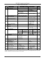
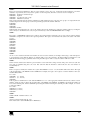
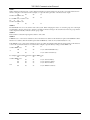
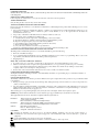
Kramer Electronics, Ltd.
USER MANUAL
Model:
VP-23DS
Presentation Switcher / Scaler
Contents
Contents
1
2
2.1
3
4
5
6
6.1
7
7.1
7.2
8
8.1
8.2
8.3
9
10
10.1
11
Introduction
Getting Started
Quick Start
Overview
Your VP-23DS Presentation Switcher / Scaler
Installing the VP-23DS on a Rack
Connecting the VP-23DS Presentation Switcher / Scaler
Connecting a PC
Operating the VP-23DS Presentation Switcher / Scaler
Operating your Switcher
Operating the Scaler Section
Flash Memory Upgrade
Downloading from the Internet
Connecting the PC to the RS-232 Port
Upgrading Firmware
Technical Specifications
Hex Tables
Audio Gain Control Hex Tables
VP-23DS Communication Protocol
1
1
1
3
3
7
8
10
11
11
12
13
13
13
13
19
20
20
21
Figures
Figure 1: VP-23DS Presentation Switcher / Scaler
Figure 2: Connecting the VP-23DS Presentation Switcher / Scaler
Figure 3: Connecting a PC without using a Null-modem Adapter
Figure 4: Setting the DIP to Flash Program
Figure 5: Splash Screen
Figure 6: Atmel – Flip Window
Figure 7: Device Selection Window
Figure 8: Selecting the Device from the Selection Window
Figure 9: Loading the Hex
Figure 10: RS-232 Window
Figure 11: Atmel – Flip Window (Connected)
Figure 12: Atmel – Flip Window (Operation Completed)
Figure 13: Setting the DIP to Normal
4
9
10
13
14
14
15
15
16
16
17
18
18
i
Contents
Tables
Table 1: Front Panel VP-23DS Presentation Switcher / Scaler Features
Table 2: Rear Panel VP-23DS Presentation Switcher / Scaler Features
Table 3: Technical Specifications of the VP-23DS Presentation Switcher
Table 4: VP-23DS Hex Table
Table 5: VP-23DS Master Audio Selector Hex Table
Table 6: Set the Relative Audio Output
Table 7: Increase or Decrease the Audio Output Gain by One Step
Table 8: Protocol Definitions
Table 9: Instruction Codes
ii
5
6
19
20
20
20
20
21
22
KRAMER: SIMPLE CREATIVE TECHNOLOGY
Introduction
1
Introduction
Welcome to Kramer Electronics (since 1981): a world of unique, creative and
affordable solutions to the infinite range of problems that confront the video,
audio and presentation professional on a daily basis. In recent years, we have
redesigned and upgraded most of our line, making the best even better! Our
500-plus different models now appear in 8 Groups1, which are clearly defined
by function.
Congratulations on purchasing your Kramer VP-23DS Presentation Switcher /
Scaler. This product is ideal for the following typical applications:
Presentation and conference room systems, board rooms and auditoriums
Production studios
Rental and staging
The package includes the following items:
VP-23DS Presentation Switcher / Scaler
Power cord and Null-modem adapter
Windows®-based Kramer control software2
This user manual3
2
Getting Started
We recommend that you:
Unpack the equipment carefully and save the original box and packaging
materials for possible future shipment
Review the contents of this user manual
Use Kramer high performance high resolution cables4
2.1 Quick Start
This quick start chart summarizes the basic setup and operation steps.
1 GROUP 1: Distribution Amplifiers; GROUP 2: Video and Audio Switchers, Matrix Switchers and Controllers; GROUP 3:
Video, Audio, VGA/XGA Processors; GROUP 4: Interfaces and Sync Processors; GROUP 5: Twisted Pair Interfaces;
GROUP 6: Accessories and Rack Adapters; GROUP 7: Scan Converters and Scalers; and GROUP 8: Cables and Connectors
2 Downloadable from our Web site at http://www.kramerelectronics.com
3 Download up-to-date Kramer user manuals from our Web site at http://www.kramerelectronics.com
4 The complete list of Kramer cables is on our Web site at http://www.kramerelectronics.com
1
Getting Started
2
KRAMER: SIMPLE CREATIVE TECHNOLOGY
Overview
3
Overview
The Kramer VP-23DS is a high quality presentation switcher / Scaler
designed for a wide variety of presentation and multimedia applications. The
VP-23DS includes three independently controlled switcher groups that
combine the functions of a 2x1 switcher for composite video, a 2x1 switcher
for s-Video, and a 4x1 switcher for computer graphics VGA/UXGA type
signals. Each video input has its own unbalanced stereo audio input. There is
also an independent unbalanced stereo master audio output, which can select a
signal from any of the eight audio inputs.
The VP-23DS features an additional Scaler output at which the selected video
signal (composite or s-Video) is converted to a VGA output (resolution can be
scaled up to WXGA).
In addition, the VP-23DS:
Includes eight input selector buttons, control buttons for the master audio
output level, microphone level, as well as buttons for selecting the Scaler
mode and the Scaler resolution
Features a FOLLOW button to toggle between the follow and breakaway
mode
Has a LOCK button to prevent unintentional tampering with the front
panel buttons
Is designed so that each switcher group can be controlled independently
from the other sections
Lets you insert an additional microphone channel by mixing with the
master output signal or by muting the master output signal
The VP-23DS can be controlled via the front panel buttons or by RS-232
serial commands transmitted by a touch screen system, PC, or other serial
controller. It is housed in a 19” 1U rack mountable enclosure, with rack “ears”
included, and is fed from a 100-240 VAC universal switching power supply.
To achieve the best performance:
Connect only good quality connection cables, thus avoiding interference,
deterioration in signal quality due to poor matching, and elevated noiselevels (often associated with low quality cables)
Avoid interference from neighboring electrical appliances and position
your Kramer VP-23DS away from moisture, excessive sunlight and dust
4
Your VP-23DS Presentation Switcher / Scaler
Figure 1 illustrates the front and rear panels of the VP-23DS. Tables 1 and 2
define the front and rear panels of the VP-23DS, respectively.
3
4
Figure 1: VP-23DS Presentation Switcher / Scaler
Your VP-23DS Presentation Switcher / Scaler
KRAMER: SIMPLE CREATIVE TECHNOLOGY
Your VP-23DS Presentation Switcher / Scaler
Table 1: Front Panel VP-23DS Presentation Switcher / Scaler Features
#
1
2
Feature
POWER Switch
SCALER1
MODE INPUT
Buttons
3
4
5
6
7
8
9
10
11
12
13
14
15
16
17
18
19
Function
Illuminated switch for turning the unit ON or OFF
2
FOLLOW
Press so that the scaler output will follow the last
selected video input
Release to select the scaler output independently (by
pressing the CV, Y/C or VGA/UXGA scaler buttons)
3
CV
Press to route the selected CV input to the scaled
4
output
3
Y/C
Press to route the selected Y/C input to the scaled
4
output
VGA/UXGA Press to route the selected VGA/UXGA input to the
4
scaled output
Note that the VGA/UXGA is not scaled. It is routed
directly to the scaled output
RES
Buttons
INPUT
SELECTOR
AUDIO
LEVEL
VGA
SVGA
XGA
WXGA
VIDEO (CV) Buttons
s-VIDEO (Y/C) Buttons
VGA/UXGA Button
- Button
MASTER
+ Button
+ Button
MIC
- Button
MUTE Button
MIX Button
LOCK Button
Press to select the VGA (640x480) output resolution
Press to select the SVGA (800x600) output resolution
Press to select the XGA (1024x768) output resolution
Press to select the WXGA (1366x768) output resolution
Select the composite video and audio input (from 1 to 2)
Select the s-Video and audio input (from 1 to 2)
Select the VGA/UXGA video and audio input (from 1 to 4)
Decrease the master audio signal level
Increase the master audio signal level
Increase the microphone audio signal level
Decrease the microphone audio signal level
Press to disable/enable the Master Audio output5
Press to toggle. When on, will mix the microphone signal
with the Master Audio output6. When OFF, the
microphone signal is not available at the master audio
output
Press and hold7 to lock/unlock the front panel buttons
1 See section 7.2
2 Button illuminates
3 Scaled according to the resolution selected using the RES button
4 In the FOLLOW mode, the button illuminates if this is the last input routed to the master output. In the breakaway mode,
press to select the input to route to the scaler output
5 Except for the microphone signal in the MIX mode
6 When the MUTE button and the MIX button are on, only the microphone signal is transferred to the output
7 For about 2 seconds
5
Your VP-23DS Presentation Switcher / Scaler
Table 2: Rear Panel VP-23DS Presentation Switcher / Scaler Features
#
20
21
22
23
24
25
26
27
28
29
30
31
32
33
34
Feature
CV IN RCA Connectors
YC IN 4p Connectors
YC OUT 4p Connector
CV OUT RCA Connector
VGA/UXGA IN HD15 Connectors
VGA/UXGA OUT HD15 Connector
SCALER OUT HD15 Connector
RS-232 Connector
VGA/UXGA AUDIO INPUTS 3.5mm Mini
Jack Connectors
CV AUDIO IN RCA Connectors (L and R)
Function
Connect to the composite video sources (from IN 1 to IN 2)
Connect to the s-Video sources (from IN 1 to IN 2)
Connect to the s-Video acceptor
Connect to the composite video acceptor
Connect to the VGA/UXGA video sources (from IN 1 to 4)
Connect to the VGA/UXGA video acceptor
Connect to the VGA-UXGA acceptor1
DB 9F connector connects to PC or Remote Controller
Connect to the VGA/UXGA unbalanced stereo audio sources
(from 1 to 4)
Connect to the CV unbalanced stereo audio sources
(from 1 to 2)
YC AUDIO IN RCA Connectors (L and R) Connect to the s-Video unbalanced stereo audio sources
(from 1 to 2)
2
MASTER AUDIO OUT RCA Connectors Connect to the stereo audio acceptor
Dipswitches
FLASH PROGRAM
Select between NORMAL for normal operation (the factory
default), and FLASH PROGRAM to upgrade to the latest
Kramer firmware (see section 8)
COND / DYN MIC
Select between a condenser and a dynamic microphone
MIC IN 6.3mm Phone Jack Connector
Connects to the microphone
Power Connector with Fuse
AC connector enabling power supply to the unit
1 Displays the scaled output
2 The input selector button last pressed transmits the audio input signal of the selected channel to the master audio output
6
KRAMER: SIMPLE CREATIVE TECHNOLOGY
Installing the VP-23DS on a Rack
5
Installing the VP-23DS on a Rack
This section describes what to do before installing on a rack and how to rack
mount.
Before Installing on a Rack
Before installing on a rack, be sure that the environment is
within the recommended range:
How to Rack Mount
To rack-mount a machine:
1
Attach both ear brackets to the
machine. To do so, remove the
screws from each side of the machine
(3 on each side), and replace those
screws through the ear brackets.
2
Place the ears of the machine
against the rack rails, and insert the
proper screws (not provided) through
each of the four holes in the rack
ears.
Operating temperature range +5 to +45 Deg. Centigrade
Operating humidity range
5 to 65% RHL, non-condensing
Storage temperature range
-20 to +70 Deg. Centigrade
Storage humidity range
5 to 95% RHL, non-condensing
CAUTION!!
When installing on a 19" rack, avoid hazards by taking
care that:
1 It is located within the recommended environmental
conditions, as the operating ambient temperature of a
closed or multi unit rack assembly may exceed the
room ambient temperature.
2 Once rack mounted, enough air will still flow around the
machine.
3 The machine is placed straight in the correct horizontal
position.
4 You do not overload the circuit(s). When connecting
the machine to the supply circuit, overloading the
circuits might have a detrimental effect on overcurrent
protection and supply wiring. Refer to the appropriate
nameplate ratings for information. For example, for
fuse replacement, see the value printed on the product
label.
5 The machine is earthed (grounded) in a reliable way
and is connected only to an electricity socket with
grounding. Pay particular attention to situations where
electricity is supplied indirectly (when the power cord is
not plugged directly into the socket in the wall), for
example, when using an extension cable or a power
strip, and that you use only the power cord that is
supplied with the machine.
Note that:
In some models, the front panel
may feature built-in rack ears
Detachable rack ears can be removed
for desktop use
Always mount the machine in the rack
before you attach any cables or
connect the machine to the power
If you are using a Kramer rack adapter
kit (for a machine that is not 19"), see
the Rack Adapters user manual for
installation instructions (you can
download it at:
http://www.kramerelectronics.com)
7
Connecting the VP-23DS Presentation Switcher / Scaler
6
Connecting the VP-23DS Presentation Switcher / Scaler
In Figure 2, the audio input connections are not shown, except for the
microphone and the MASTER AUDIO OUT. In this example, all the outputs
are connected to the same projector. Use the projector controller to switch
between the VP-23DS video outputs1.
To connect2 the VP-23DS, as illustrated in the example in Figure 2, do the
following3:
1. Connect the following video sources:
One4 composite video source (for example, composite video
player 1) to the CV IN 1 RCA connector
One4 composite video source (for example, a composite video
player 2) to the CV IN 2 RCA connector
One s-Video source (for example, s-Video player 1) to the YC IN 1
4p connector
One s-Video source (for example, s-Video player 2) to the YC IN 2
4p connector
One4 VGA/UXGA source (for example, a computer graphics
source) to the VGA/UXGA IN 1 HD15F connector
2. Connect the acceptors to a projector5 as follows:
The composite video CV OUT RCA connector to the composite
video input of the projector
The s-Video YC OUT 4p connector to the s-Video input of the
projector
The VGA/UXGA OUT HD15F connector to the VGA/UXGA input
of the projector
3. Connect the SCALER OUT HD15F connector to an acceptor (for example, a
VGA display).
4. Connect the appropriate unbalanced stereo audio sources (not shown in
Figure 2).
5. Connect the MASTER AUDIO OUT RCA connectors to an amplifier with
speakers.
1 Or the projector inputs
2 You do not need to connect all the inputs
3 Switch OFF the power on each device before connecting it to your VP-23DS. After connecting your VP-23DS, switch on its
power and then switch on the power on each device. Switching on the VP-23DS, recalls the previous setup from the nonvolatile memory
4 Although in this example not all the sources are connected, you can connect all of the inputs, that is, eight in total
5 In this example a projector is used, but you can also connect separate outputs such as displays, video recorders and so on
8
KRAMER: SIMPLE CREATIVE TECHNOLOGY
Connecting the VP-23DS Presentation Switcher / Scaler
6. If required, connect a dynamic or a condenser microphone1 to the MIC IN
6.3mm phone jack connector.
7. As an option, you can connect a PC and/or controller to the RS-232 port (see
section 6.1).
8. Connect the power cord (not shown in Figure 2).
Figure 2: Connecting the VP-23DS Presentation Switcher / Scaler
1 Use the DYN / COND MIC switch (on the rear panel) to select a dynamic microphone or a condenser
9
Connecting the VP-23DS Presentation Switcher / Scaler
6.1 Connecting a PC
You can connect a PC (or other controller) to the VP-23DS via the RS-232 port.
To connect using the Null-modem adapter provided with the machine
(recommended method):
Connect the RS-232 DB9 rear panel port on the VP-23DS to the
Null-modem adapter and connect the Null-modem adapter with a 9-wire
flat cable to the RS-232 DB9 port on your PC
To connect without using a Null-modem adapter:
Connect the RS-232 DB9 port on your PC to the RS-232 DB9 rear panel
port on the VP-23DS, as Figure 3 illustrates
PIN 5 Connected to PIN 5 (Ground)
PIN 3 Connected to PIN 2
PIN 2 Connected to PIN 3
Female DB9 (From PC)
Male DB9
PIN 4 Connected to PIN 6
PINS 8, 7, 1 Connected together
If a Shielded cable is used, connect the shield to PIN 5
Figure 3: Connecting a PC without using a Null-modem Adapter
10
KRAMER: SIMPLE CREATIVE TECHNOLOGY
Operating the VP-23DS Presentation Switcher / Scaler
7
Operating the VP-23DS Presentation Switcher / Scaler
You can operate your VP-23DS via:
The front panel buttons
RS-232 serial commands transmitted by a touch screen system, PC, or
other serial controller
The front panel buttons include the:
Switcher section buttons: the INPUT SELECTOR buttons, the MASTER
and MIC AUDIO LEVEL BUTTONS, and the MUTE, LOCK and MIX
buttons
Scaler section buttons: the FOLLOW, CV, Y/C and VGA/UXGA MODEINPUT buttons, as well as the VGA, SVGA, XGA and WXGA resolution
buttons
7.1 Operating your Switcher
You can select the video signals within each switcher group by pressing the
relevant INPUT SELECTOR1 buttons. You can switch one2 of the:
Two composite video (CV) inputs to the composite video output
Two s-Video (Y/C) inputs to the s-Video output
Four VGA/UXGA inputs to the VGA/UXGA output
The selected button in each group is illuminated in red3.
The VP-23DS operates in the audio-follow-video4 (AFV) mode so that the
audio signal follows the selected video input signal.
The audio signal is routed to the MASTER AUDIO OUT output, therefore the
last INPUT SELECTOR button selected (from any of the switcher groups)
will route the audio signal of that input to the audio output.
The last selected button is illuminated in purple to indicate the source of the
outputted audio signal
1 You can overlook a switcher group and choose not to select a button from it
2 You cannot select more than one button in a group
3 Pressing an illuminated button for more than 2 seconds will disconnect the output and the button will no longer illuminate
4 In which all operations relate to both the video and the audio channels
11
Operating the VP-23DS Presentation Switcher / Scaler
When setting the master audio gain to its minimum, the MUTE button illuminates.
When MIX is OFF, then the microphone signal is not available at the master
audio output.
When MIX is ON and MUTE is OFF, the microphone signal is mixed with the
master audio output.
When both the MUTE and MIX buttons are ON, only the microphone signal
is transferred to the master output.
The MUTE and MIX buttons can be turned ON or OFF via RS-232 control
and their respective buttons on the front panel illuminate.
7.2 Operating the Scaler Section
The SCALER section can operate in the FOLLOW or the breakaway mode:
In the FOLLOW mode, the FOLLOW button illuminates, and the Scaler
output follows the last selected video input
For example, if the last selected input is VIDEO (CV) 2, its INPUT
SELECTOR button is illuminated (in purple) and in the SCALER
section, the CV button illuminates (as well as the FOLLOW button)
indicating that CV INPUT 2 is scaled and routed to the SCALER output
In the Scaler breakaway mode, the FOLLOW button is not illuminated
and the input to the SCALER output is selected by pressing appropriate
SCALER button
For example, if the last selected master output is s-VIDEO (Y/C) 2,
select the Scaler output by pressing one of the three SCALER buttons:
CV, Y/C or VGA/UXGA
You can select the desired Scaler output resolution by pressing one of the four
resolution buttons: VGA, SVGA, XGA or WXGA.
12
KRAMER: SIMPLE CREATIVE TECHNOLOGY
Flash Memory Upgrade
8
Flash Memory Upgrade
The VP-23DS firmware is located in FLASH memory, which lets you
upgrade to the latest Kramer firmware version in minutes! The process
involves:
Downloading from the Internet (see section 8.1)
Connecting the PC to the RS-232 port (see section 8.2)
Upgrading Firmware (see section 8.3)
8.1 Downloading from the Internet
You can download the up-to-date file1 from the Internet. To do so:
1. Go to our Web site at http://www.kramerelectronics.com and download the
file: “FLIP_VP23DS.zip” from the Technical Support section.
2. Extract the file: “FLIP_VP23DS.zip” to a folder (for example, C:\Program
Files\Kramer Flash).
3. Create a shortcut on your desktop to the file: “FLIP.EXE”.
8.2 Connecting the PC to the RS-232 Port
Before installing the latest Kramer firmware version on a VP-23DS unit, do
the following:
1. Disconnect the power on the VP-23DS.
2. Connect the RS-232 DB9 rear panel port on the
VP-23DS unit to the Null-modem adapter and connect
the Null-modem adapter with a 9-wire flat cable to the
RS-232 DB9 COM port on your PC (see section 6.1).
3. On the rear panel, set the FLASH PROG DIP to Flash
Program (by setting the FLASH PROG DIP
downwards, see Figure 4).
4. Connect the power on the VP-23DS unit and switch it
ON.
Figure 4: Setting
the DIP to Flash
Program
8.3 Upgrading Firmware
Follow these steps to upgrade the firmware:
1. Double click the desktop icon: “Shortcut to FLIP.EXE”.
The Splash screen appears as follows:
1 The files indicated in this section are given as an example only. These file names are liable to change from time to time
13
Flash Memory Upgrade
Figure 5: Splash Screen
2. After a few seconds, the Splash screen is replaced by the “Atmel – Flip”
window:
Figure 6: Atmel – Flip Window
3. Press the keyboard shortcut key F2 (or select the “Select” command from the
Device menu, or press the integrated circuit icon in the upper right corner of
the window).
The “Device Selection” window appears:
14
KRAMER: SIMPLE CREATIVE TECHNOLOGY
Flash Memory Upgrade
Figure 7: Device Selection Window
4. Click the button next to the name of the device and select from the list:
AT89C51RD2:
AT89C51RD2
T89C51RD2
Figure 8: Selecting the Device from the Selection Window
5. Click OK and select “Load Hex” from the File menu.
15
Flash Memory Upgrade
A
Figure 9: Loading the Hex
6. The Open File window opens. Select the correct HEX file that contains the
updated version of the firmware for VP-23DS (for example,
23DSM_V1p2.hex) and click Open.
7. Press the keyboard shortcut key F3 (or select the “Communication / RS232”
command from the Settings menu, or press the keys: Alt SCR).
The “RS232” window appears. Change the COM port according to the
configuration of your computer and select the 9600 baud rate:
Figure 10: RS-232 Window
8. Click Connect.
In the “Atmel – Flip” window, in the Operations Flow column, the Run button
is active, and the name of the chip appears as the name of the third column:
AT89C51RD2.
16
KRAMER: SIMPLE CREATIVE TECHNOLOGY
Flash Memory Upgrade
Verify that in the Buffer Information column, the “HEX File: VP23DS.hex”
appears.
A
VP23DS.hex
Figure 11: Atmel – Flip Window (Connected)
9. Click Run.
After each stage of the operation is completed, the check-box for that stage
becomes colored green1.
When the operation is completed, all 4 check-boxes will be colored green and
the status bar message: Memory Verify Pass appears2:
1 See also the blue progress indicator on the status bar
2 If an error message: “Not Finished” shows, click Run again
17
Flash Memory Upgrade
A
VP23DS.hex
Figure 12: Atmel – Flip Window (Operation Completed)
10. Close the “Atmel – Flip” window.
11. Disconnect the power on the VP-23DS.
12. Disconnect the RS-232 rear panel port on the VP-23DS
unit from the Null-modem adapter.
13. On the rear panel, set the FLASH PROG DIP to normal
(by setting the FLASH PROG DIP set upwards, see
Figure 13).
Figure 13: Setting
the DIP to Normal
14. Connect the power to the VP-23DS.
18
KRAMER: SIMPLE CREATIVE TECHNOLOGY
Technical Specifications
9
Technical Specifications
Table 3 includes the technical specifications:
1
Table 3: Technical Specifications of the VP-23DS Presentation Switcher
INPUTS:
2 composite video (1Vpp/75 ) on RCA connectors
2 s-Video 1 Vpp (Y), 0.3Vpp (C) / 75 on 4p connectors
4 VGA/UXGA on HD15F connectors
4 unbalanced stereo audio on 3.5mm jack connectors (for VGA/UXGA)
+4dBm/10k
4 unbalanced stereo audio channels +4dBm / 10k on RCA connectors (2 for
CV and 2 for YC)
Mic: 3mV / 10k condenser / dynamic on a 6.3mm Phone Jack connector
OUTPUTS:
1 composite video (1Vpp/75 ) on an RCA connector
1 s-Video 1Vpp (Y), 0.3Vpp (C) / 75 on a 4p connector
1 VGA/UXGA on an HD15F connector
1 VGA/UXGA scaler out on an HD15F connector
1 unbalanced stereo master audio channel +4dBm / 50 on RCA connectors
VGA (640 x 480), SVGA (800 x 600), XGA (1024 x 768) and WXGA (1366 x
768)
VIDEO: 2.1Vpp; XGA: 0.77Vpp AUDIO: 27Vpp
VIDEO: VGA / UXGA: 400MHz; AUDIO: 40kHz
s-Video (Y): 310MHz;
Composite/SDI video: 310MHz;
HDTV compatible
<0.07% all channels
<0.05 Deg. all channels
VIDEO: 75dB all channels
AUDIO: 75dB /1 Vpp all channels
10 selector buttons, master audio level, mic audio level, mix, lock, mute, RS-232
100-240V AC, 50/60Hz, (115V AC, U.S.A.) 7VA
19-inch (W), 7-inch (D) 1U (H) rack-mountable
2.6kg (8lbs.) approx
Power cord, Null modem adapter, Windows®-based Kramer control software
SCALED OUTPUT
RESOLUTIONS:
MAX. OUTPUT LEVEL:
BANDWIDTH (-3dB):
DIFF. GAIN:
DIFF. PHASE:
S/N RATIO:
CONTROLS:
POWER SOURCE:
DIMENSIONS:
WEIGHT:
ACCESSORIES:
1 Specifications are subject to change without notice
19
Hex Tables
10 Hex Tables
Table 4 lists the Hex values (which the protocol in section 11 describes in
more detail) for the VP-23DS Presentation Switcher:
Table 4: VP-23DS Hex Table
Inputs
Group
#
Composite In 1
Video
In 2
In 1
s-Video
In 2
In 1
In 2
VGA /
UXGA
In 3
In 4
Composite Video
OUT
s-Video OUT
VGA/UXGA OUT
01 81 81 81
01 82 81 81
01 81 82 81
01 82 82 81
01 81 83 81
01 82 83 81
01 83 83 81
01 84 83 81
Table 5: VP-23DS Master Audio Selector Hex Table
Master Audio Selector
10.1
Composite Video Group
s-Video Group
02 81 81 81
02 82 81 81
VGA / UXGA Group
Microphone
02 83 81 81
02 85 81 81
Audio Gain Control Hex Tables
Table 6 and Table 7 describe the audio gain controls1:
Table 6: Set the Relative Audio Output2
Set Relative Audio Gain of Master Audio Out Gain
16 81 80 81
Mute
…
16 81 D3 81
-6dB
…
16 81 DF 81
0dB
…
16 81 EB 81
6dB
…
16 81 FF 81
16dB
Table 7: Increase or Decrease the Audio Output Gain by One Step
Master Out
Microphone
Increase
18 81 80 81
18 82 80 81
Decrease
18 81 81 81
18 82 81 81
1 When controlling the VP-23DS via RS-232, refer to note 9 for command 42 in the communication protocol (see section 11)
2 For the microphone gain control, the second byte equals 82
20
KRAMER: SIMPLE CREATIVE TECHNOLOGY
VP-23DS Communication Protocol
11 VP-23DS Communication Protocol
The VS-23DS is compatible with Kramer’s Protocol 2000 (version 0.48)
(below). This RS-232/RS-485 communication protocol uses four bytes of
information as defined below. For RS-232, a null-modem connection between
the machine and controller is used. The default data rate is 9600 baud, with no
parity, 8 data bits and 1 stop bit.
Table 8: Protocol Definitions
MSB
0
7
LSB
DESTINATION
INSTRUCTION
D
6
N5
5
N4
4
I6
6
I5
5
I4
4
O6
6
O5
5
O4
4
OVR
6
X
5
M4
4
N3
3
N2
2
N1
1
N0
0
I2
2
I1
1
I0
0
O2
2
O1
1
O0
0
M1
1
M0
0
1st byte
1
7
INPUT
I3
3
2nd byte
1
7
OUTPUT
O3
3
3rd byte
1
7
M3
3
MACHINE NUMBER
M2
2
4th byte
1st BYTE:
Bit 7 – Defined as 0.
D – “DESTINATION” :
0 - for sending information to the switchers (from the PC);
1 - for sending to the PC (from the switcher).
N5…N0 – “INSTRUCTION”
The function that is to be performed by the switcher(s) is defined by the INSTRUCTION (6 bits). Similarly, if a function is
performed via the machine’s keyboard, then these bits are set with the INSTRUCTION NO., which was performed. The
instruction codes are defined according to the table below (INSTRUCTION NO. is the value to be set for N5…N0).
2nd BYTE:
Bit 7 – Defined as 1.
I6…I0 – “INPUT” .
When switching (ie. instruction codes 1 and 2), the INPUT (7 bits) is set as the input number which is to be switched.
Similarly, if switching is done via the machine’s front-panel, then these bits are set with the INPUT NUMBER which was
switched. For other operations, these bits are defined according to the table.
3rd BYTE:
Bit 7 – Defined as 1.
O6…O0 – “OUTPUT” .
When switching (ie. instruction codes 1 and 2), the OUTPUT (7 bits) is set as the output number which is to be switched.
Similarly, if switching is done via the machine’s front-panel, then these bits are set with the OUTPUT NUMBER which was
switched. For other operations, these bits are defined according to the table.
4th BYTE:
Bit 7 – Defined as 1.
Bit 5 – Don’t care.
OVR – Machine number override.
M4…M0 – MACHINE NUMBER.
Used to address machines in a system via their machine numbers. When several machines are controlled from a single serial
port, they are usually configured together with each machine having an individual machine number. If the OVR bit is set, then
all machine numbers will accept (implement) the command, and the addressed machine will reply.
For a single machine controlled via the serial port, always set M4…M0 = 1, and make sure that the machine itself is
configured as MACHINE NUMBER = 1.
21
VP-23DS Communication Protocol
Table 9: Instruction Codes
#
0
1
2
5
6
INSTRUCTION
DESCRIPTION
RESET MACHINE
SWITCH GROUPS
SWITCH AUDIO OUTPUTS TO
MASTER AUDIO OUT
REQUEST GROUP STATUS
DEFINITION FOR SPECIFIC INSTRUCTION
INPUT
OUTPUT
0
1-2
0
1-2 (1 – for CV group, 2 –
for SV group)
3 – for VGA group
4 – for Scaler
3
10
REQUEST STATUS OF
MASTER AUDIO OUTPUT
BREAKAWAY SETTING
1
9
VIDEO/AUDIO TYPE SETTING
2 – for scaler resolution
11
0
16
REQUEST BREAKAWAY
SETTING
REQUEST VIDEO/AUDIO TYPE
SETTING
ERROR
18
22
RESET MACHINE
SET AUDIO PARAMETER
0
Parameter
0 – Scaler FOLLOW mode
1 – Scaler Normal mode
1 – VGA (640x480)
2 – SVGA (800x600)
3 – XGA (1024x768)
4 - WXGA
1 – Request Scaler
"FOLLOW" setting
2 – for scaler resolution
0
Don’t care
0 – Invalid instruction
1 – Out of range
6 – Receive buffer overflow
0
Parameter
Value:
Value
Audio gain:
55
1 – Audio Master
2 –Microphone
Mix
0
microphone:
INCREASE/DECREASE AUDIO 1 – audio master
PARAMETER
2 – microphone
REQUEST AUDIO PARAMETER Equal to input / output number
whose parameter is requested
1 – audio master
2 – microphone
LOCK FRONT PANEL
0 – Panel unlocked
1 – Panel locked
REQUEST WHETHER PANEL
0
IS LOCKED
AUDIO PARAMETER
0
SETTINGS FOR
INSTRUCTIONS 22, 25
REPLY ON
0
57
SET AUTO SAVE
61
IDENTIFY MACHINE
62
DEFINE MACHINE
24
25
30
31
42
1
2
1-4
1 – from CV group
2 – from SV group
3 – from VGA group
Set equal to video (and audio)
Set equal to group to which
input to be switched for the relative output is to be switched
group
1-4* Set equal to audio output to
1
be switched to Master Audio out
0
1-4 Set equal to the group of
which status is required
0
1
8
12
NOTE
1 – Autosave
2 – No save
1 or 2 – Machine name
3 or 4 – Program version
8 – Number of inputs
4 – Number of outputs
Audio gain:
2
3
11
3,12
3,12
4
1
2, 7, 8,
9,
0-127
Mix
0 – mix OFF
microphone: 1 – Mix ON
0 - increase output
1 - decrease output
0
8
0
2
0
3
0 - Gain
4 - Mix mode
9
0 - Off
1 - On
0 – request first 4 digits
1 – request first suffix
10 – request first prefix
1 – For video
2 – For audio
9
5
6
3
NOTE 1
When the master switcher is reset, (e.g. when it is turned on), the reset code is sent to the PC. If this code is sent to the
switchers, it will reset according to the present power-down settings.
22
KRAMER: SIMPLE CREATIVE TECHNOLOGY
VP-23DS Communication Protocol
NOTE 2
These are bi-directional definitions. That is, if the switcher receives the code, it will perform the instruction; and if the
instruction is performed (due to a keystroke operation on the front panel), then these codes are sent. For example, if:
0000 0001 Instruction “ Switch Groups”
1000 0010 Input #2
1000 0001 in composite video group
1000 0001 Machine #1 (master)
Was sent from the PC, then the switcher (machine #1) will switch input 2 in composite video group to its output. If the user
switched input 4 in the VGA group via the front panel keypad, then the switcher will send:
0100 0001
1000 0100
1000 0100
1000 0001 to the PC.
When the PC sends instruction #1 or #2 to the switcher, then, if the instruction is valid, the switcher replies by sending the
same four bytes to the PC that were sent (except for the first byte, where the DESTINATION bit is set high).
NOTE 3
The reply to a “ REQUEST” instruction is as follows: the same instruction and input codes as were sent are returned, and the
OUTPUT is assigned to the value of the requested parameter. The reply to the instruction #5 (what is the status of the VGA
group?):
0000 0101
1000 0000
1000 0011
1000 0001
Would be:
0100 0101
1000 0000
1000 0100
1000 0001
NOTE 4
An error code is returned to the PC if an invalid code was sent to the switcher (for example, when trying to switch an input or
a group which is greater than the highest one defined). This code is also returned to the PC if an RS-232 instruction is sent
while the machine is being programmed via the front panel. Reception of this code by the switcher will not be valid.
NOTE 5
Under normal conditions, the machine’ s present status is saved each time a change is made. The power-down save (the auto
save) may be disabled using this code. Note that each time that the machine is turned ON, the auto save function is
automatically set.
NOTE 6
This is a request to identify the switchers in a system. If the INPUT is set as 1 or 2, the machine will send its name. The reply
is the decimal value of the INPUT and the OUTPUT. For example, the reply to the request to send the machine’ s name (for
machine #001) will be:
0111 1101
1000 0000 (i.e. 128+0)
1001 0111 (i.e. 128+23)
1000 0001
If the request for identification is sent with the INPUT set as 3 or 4, the appropriate machine will send its software version
number. Again, the reply would be the decimal value of the INPUT and OUTPUT - the INPUT representing the number in
front of the decimal point, and the OUTPUT representing the number following the decimal point. For example, for version
3.5 the reply will be:
0111 1101
1000 0011 (i.e. 128+3)
1000 0101 (i.e. 128+5)
1000 0001
NOTE 7
GAIN VALUE – Number from 0 to 127
NOTE 8
Answer = Current Audio Gain (0 –127)
If the Audio Gain = 0, the MUTE button is illuminated
23
VP-23DS Communication Protocol
NOTE 9
When changing parameters (mix or gain), further information needed in instructions 22 and 25 is sent using instruction 42 –
which is sent prior to the instruction. For example, to request the audio gain value of the master audio output
2A
80
80
81
and then send HEX codes
19
81
80
81.
To set MIX mode, send hex codes
2A
81 84
81
and then send HEX codes
16
80
81
81
NOTE 10
The FOLLOW mode is for the switcher and scaler system. When changing the status of a switcher group, the scaler input
automatically connects to that group'
s output. For example, if the latest change in the switcher was in the SV group, then the
scaler'
s input automatically connects to the SV group output
NOTE 11
This instruction selects the input signal resolutions of the scaler
NOTE 12
If INPUT is set to 127 for these instructions, then, if the function is defined on this machine, it replies with OUTPUT=1. If the
function is not defined, then the machine replies with OUTPUT=0, or with an error (invalid instruction code).
If the INPUT is set to 126 for these instructions, then, if possible, the machine will return the current setting of this function,
even for the case that the function is not defined. For example, request breakaway setting would be HEX code:
0B
80
80
81
would be HEX codes:
4B
80
80
81 (for Scaler FOLLOW mode)
or:
4B
80
81
81 (for Scaler normal mode)
For example, request Scaler resolution would be HEX codes:
0C
80
80
81
would be HEX codes:
0C
80
81
81 (for VGA resolution)
0C
80
82
81 (for SVGA resolution)
0C
80
83
81 (for XGA resolution)
and
0C
80
84
81 (for WXGA resolution)
24
KRAMER: SIMPLE CREATIVE TECHNOLOGY
LIMITED WARRANTY
Kramer Electronics (hereafter Kramer) warrants this product free from defects in material and workmanship under the
following terms.
HOW LONG IS THE WARRANTY
Labor and parts are warranted for seven years from the date of the first customer purchase.
WHO IS PROTECTED?
Only the first purchase customer may enforce this warranty.
WHAT IS COVERED AND WHAT IS NOT COVERED
Except as below, this warranty covers all defects in material or workmanship in this product. The following are not covered
by the warranty:
1. Any product which is not distributed by Kramer, or which is not purchased from an authorized Kramer dealer. If you are
uncertain as to whether a dealer is authorized, please contact Kramer at one of the agents listed in the Web site
www.kramerelectronics.com.
2. Any product, on which the serial number has been defaced, modified or removed.
3. Damage, deterioration or malfunction resulting from:
i) Accident, misuse, abuse, neglect, fire, water, lightning or other acts of nature
ii) Product modification, or failure to follow instructions supplied with the product
iii) Repair or attempted repair by anyone not authorized by Kramer
iv) Any shipment of the product (claims must be presented to the carrier)
v) Removal or installation of the product
vi) Any other cause, which does not relate to a product defect
vii) Cartons, equipment enclosures, cables or accessories used in conjunction with the product
WHAT WE WILL PAY FOR AND WHAT WE WILL NOT PAY FOR
We will pay labor and material expenses for covered items. We will not pay for the following:
1. Removal or installations charges.
2. Costs of initial technical adjustments (set-up), including adjustment of user controls or programming. These costs are the
responsibility of the Kramer dealer from whom the product was purchased.
3. Shipping charges.
HOW YOU CAN GET WARRANTY SERVICE
1. To obtain service on you product, you must take or ship it prepaid to any authorized Kramer service center.
2. Whenever warranty service is required, the original dated invoice (or a copy) must be presented as proof of warranty
coverage, and should be included in any shipment of the product. Please also include in any mailing a contact name,
company, address, and a description of the problem(s).
3. For the name of the nearest Kramer authorized service center, consult your authorized dealer.
LIMITATION OF IMPLIED WARRANTIES
All implied warranties, including warranties of merchantability and fitness for a particular purpose, are limited in duration to
the length of this warranty.
EXCLUSION OF DAMAGES
The liability of Kramer for any effective products is limited to the repair or replacement of the product at our option. Kramer shall
not be liable for:
1. Damage to other property caused by defects in this product, damages based upon inconvenience, loss of use of the product, loss
of time, commercial loss; or:
2. Any other damages, whether incidental, consequential or otherwise. Some countries may not allow limitations on how long an
implied warranty lasts and/or do not allow the exclusion or limitation of incidental or consequential damages, so the above
limitations and exclusions may not apply to you.
This warranty gives you specific legal rights, and you may also have other rights, which vary from place to place.
NOTE: All products returned to Kramer for service must have prior approval. This may be obtained from your dealer.
This equipment has been tested to determine compliance with the requirements of:
EN-50081:
EN-50082:
CFR-47:
"Electromagnetic compatibility (EMC);
generic emission standard.
Part 1: Residential, commercial and light industry"
"Electromagnetic compatibility (EMC) generic immunity standard.
Part 1: Residential, commercial and light industry environment".
FCC Rules and Regulations:
Part 15: “ Radio frequency devices
Subpart B Unintentional radiators”
CAUTION!
Servicing the machines can only be done by an authorized Kramer technician. Any user who makes changes or
modifications to the unit without the expressed approval of the manufacturer will void user authority to operate the
equipment.
Use the supplied DC power supply to feed power to the machine.
Please use recommended interconnection cables to connect the machine to other components.
25
For the latest information on our products and a list of Kramer
distributors, visit our Web site: www.kramerelectronics.com,
where updates to this user manual may be found.
We welcome your questions, comments and feedback.
Safety Warning:
Disconnect the unit from the power supply before
opening/servicing.
Caution
Kramer Electronics, Ltd.
Web site: www.kramerelectronics.com
E-mail: [email protected]
P/N: 2900-000295 REV 2