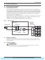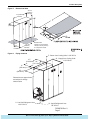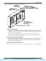
1
Precision Cooling for
Business Critical Continuity
Liebert XDC™
User Manual
50 and 60 Hz, 130 & 160kW Nominal Cooling Capacity
http://splitoff.ru/tehn-doc.html
,
,
,
.
GENERAL SAFETY GUIDELINES
!
WARNING
!
WARNING
Risk of electric shock. Can cause injury or death.
Disconnect local and remote power supplies before working within.
Before proceeding with installation of XDC, read all instructions, verify that all the parts are
included, and check the nameplate to be sure the XDC voltage matches available utility
power.
Follow all local codes.
Risk of unit falling over. Can cause injury or death.The XDC is top-heavy. Use extreme
caution and care when moving and installing this unit.
NOTE
This document shall be used together with site specific documentation and documentation for
other parts of the system (heat rejection devices and cooling modules).
NOTE
Before any action that could cause a disturbance in the XD system’s cooling function is begun,
the facility manager MUST be informed. In addition, after the action is taken and the work is
finished, the facility manager MUST be informed.
!
Figure i
CAUTION
Risk of piping and component rupture. May cause injury or equipment damage. Closing
service valves may isolate liquid refrigerant, causing high pressure and rupture of piping. Do
not close valves without follow recommended procedures for repair, maintenance and
replacement of components. Installing pressure relief valves in field piping that may become
isolated by service valves.
Model number nomenclature
Example: XDC160AA– –0
XD
C
Chiller
unit
Liebert
X-treme heat
Density system
160
A
A
A = Air
W = Water
G = Glycol
(heat rejection method)
160kW
nominal
capacity
–
–
Place holder
A = 460V-3ph-60Hz
(voltage-phase-frequency)
M = 380/420-3ph-50Hz
0
Revision
level
Place holder
: http://splitoff.ru/tehn-doc.html
TABLE OF CONTENTS
GENERAL SAFETY GUIDELINES . . . . . . . . . . . . . . . . . . . . . . . . . . . . . . . . . . . INSIDE FRONT COVER
1.0
PRODUCT DESCRIPTION . . . . . . . . . . . . . . . . . . . . . . . . . . . . . . . . . . . . . . . . . . . . . . . . . . .1
1.1
General Product Information. . . . . . . . . . . . . . . . . . . . . . . . . . . . . . . . . . . . . . . . . . . . . . . . . . . 1
1.1.1
Product/System Description. . . . . . . . . . . . . . . . . . . . . . . . . . . . . . . . . . . . . . . . . . . . . . . . . . . . . 1
1.2
Equipment Inspection . . . . . . . . . . . . . . . . . . . . . . . . . . . . . . . . . . . . . . . . . . . . . . . . . . . . . . . . 1
1.3
Equipment Handling . . . . . . . . . . . . . . . . . . . . . . . . . . . . . . . . . . . . . . . . . . . . . . . . . . . . . . . . . 1
1.3.1
1.3.2
1.3.3
1.4
Mechanical Considerations . . . . . . . . . . . . . . . . . . . . . . . . . . . . . . . . . . . . . . . . . . . . . . . . . . . . 4
1.4.1
1.5
Handling With Skid . . . . . . . . . . . . . . . . . . . . . . . . . . . . . . . . . . . . . . . . . . . . . . . . . . . . . . . . . . . 2
Removal of Skid . . . . . . . . . . . . . . . . . . . . . . . . . . . . . . . . . . . . . . . . . . . . . . . . . . . . . . . . . . . . . . 2
Removing Piano Jacks . . . . . . . . . . . . . . . . . . . . . . . . . . . . . . . . . . . . . . . . . . . . . . . . . . . . . . . . . 4
Positioning the XDC . . . . . . . . . . . . . . . . . . . . . . . . . . . . . . . . . . . . . . . . . . . . . . . . . . . . . . . . . . . 4
High Voltage Connections . . . . . . . . . . . . . . . . . . . . . . . . . . . . . . . . . . . . . . . . . . . . . . . . . . . . . 6
1.5.1
Connecting High-Voltage Cables . . . . . . . . . . . . . . . . . . . . . . . . . . . . . . . . . . . . . . . . . . . . . . . . . 6
1.6
Extra Low Voltage Connections . . . . . . . . . . . . . . . . . . . . . . . . . . . . . . . . . . . . . . . . . . . . . . . . 9
2.0
PIPING . . . . . . . . . . . . . . . . . . . . . . . . . . . . . . . . . . . . . . . . . . . . . . . . . . . . . . . . . . . . . . .12
2.1
Recommended Pipe Size. . . . . . . . . . . . . . . . . . . . . . . . . . . . . . . . . . . . . . . . . . . . . . . . . . . . . . 12
2.2
XDC Interconnection With XDO or XDV . . . . . . . . . . . . . . . . . . . . . . . . . . . . . . . . . . . . . . . . 12
2.3
Piping Installation Method . . . . . . . . . . . . . . . . . . . . . . . . . . . . . . . . . . . . . . . . . . . . . . . . . . . 14
2.3.1
2.3.2
2.3.3
Piping Installation—R-134a Pumped Circuit . . . . . . . . . . . . . . . . . . . . . . . . . . . . . . . . . . . . . . 14
Direct Expansion (DX) Circuit—R-407c Air Cooled Units . . . . . . . . . . . . . . . . . . . . . . . . . . . . 14
Air Cooled Condenser with Lee-Temp “Flooded Condenser” Head Pressure Control System—
R-407c (DX) Circuit17
3.0
FILLING THE XDC’S CIRCUITS WITH COOLANT . . . . . . . . . . . . . . . . . . . . . . . . . . . . . . . . . 18
3.1
Filling the Pumped Circuit (R-134A) . . . . . . . . . . . . . . . . . . . . . . . . . . . . . . . . . . . . . . . . . . . 18
3.2
Filling the Direct Expansion (DX) Circuit - R-407C. . . . . . . . . . . . . . . . . . . . . . . . . . . . . . . . 19
3.3
Checklist for Proper Installation . . . . . . . . . . . . . . . . . . . . . . . . . . . . . . . . . . . . . . . . . . . . . . . 19
4.0
CHECKLIST FOR XDC STARTUP . . . . . . . . . . . . . . . . . . . . . . . . . . . . . . . . . . . . . . . . . . . . 20
5.0
MICROPROCESSOR CONTROL . . . . . . . . . . . . . . . . . . . . . . . . . . . . . . . . . . . . . . . . . . . . . . 22
5.1
Feature Overview . . . . . . . . . . . . . . . . . . . . . . . . . . . . . . . . . . . . . . . . . . . . . . . . . . . . . . . . . . . 22
5.1.1
5.2
Controls . . . . . . . . . . . . . . . . . . . . . . . . . . . . . . . . . . . . . . . . . . . . . . . . . . . . . . . . . . . . . . . . . . . 23
5.2.1
5.2.2
5.3
Display . . . . . . . . . . . . . . . . . . . . . . . . . . . . . . . . . . . . . . . . . . . . . . . . . . . . . . . . . . . . . . . . . . . . 22
Feature Overview . . . . . . . . . . . . . . . . . . . . . . . . . . . . . . . . . . . . . . . . . . . . . . . . . . . . . . . . . . . . 23
Status Display . . . . . . . . . . . . . . . . . . . . . . . . . . . . . . . . . . . . . . . . . . . . . . . . . . . . . . . . . . . . . . 23
Main Menu . . . . . . . . . . . . . . . . . . . . . . . . . . . . . . . . . . . . . . . . . . . . . . . . . . . . . . . . . . . . . . . . 23
5.3.1
5.3.2
5.3.3
5.3.4
5.3.5
Viewing or Changing Settings . . . . . . . . . . . . . . . . . . . . . . . . . . . . . . . . . . . . . . . . . . . . . . . . . .
SETPOINTS . . . . . . . . . . . . . . . . . . . . . . . . . . . . . . . . . . . . . . . . . . . . . . . . . . . . . . . . . . . . . . . .
STATUS . . . . . . . . . . . . . . . . . . . . . . . . . . . . . . . . . . . . . . . . . . . . . . . . . . . . . . . . . . . . . . . . . . .
ACTIVE ALARMS . . . . . . . . . . . . . . . . . . . . . . . . . . . . . . . . . . . . . . . . . . . . . . . . . . . . . . . . . . .
ALARM HISTORY . . . . . . . . . . . . . . . . . . . . . . . . . . . . . . . . . . . . . . . . . . . . . . . . . . . . . . . . . . .
i
: http://splitoff.ru/tehn-doc.html
23
24
24
25
25
5.3.6
5.3.7
5.3.8
5.3.9
5.3.10
5.3.11
5.3.12
5.3.13
5.3.14
5.3.15
5.3.16
5.3.17
TIME . . . . . . . . . . . . . . . . . . . . . . . . . . . . . . . . . . . . . . . . . . . . . . . . . . . . . . . . . . . . . . . . . . . . . .
DATE. . . . . . . . . . . . . . . . . . . . . . . . . . . . . . . . . . . . . . . . . . . . . . . . . . . . . . . . . . . . . . . . . . . . . .
SETUP OPERATION . . . . . . . . . . . . . . . . . . . . . . . . . . . . . . . . . . . . . . . . . . . . . . . . . . . . . . . . .
SETPT PASSWORD . . . . . . . . . . . . . . . . . . . . . . . . . . . . . . . . . . . . . . . . . . . . . . . . . . . . . . . . . .
SETUP PASSWORD . . . . . . . . . . . . . . . . . . . . . . . . . . . . . . . . . . . . . . . . . . . . . . . . . . . . . . . . .
CALIBRATE SENSORS. . . . . . . . . . . . . . . . . . . . . . . . . . . . . . . . . . . . . . . . . . . . . . . . . . . . . . .
ALARM ENABLE. . . . . . . . . . . . . . . . . . . . . . . . . . . . . . . . . . . . . . . . . . . . . . . . . . . . . . . . . . . .
ALARM TIME DELAY. . . . . . . . . . . . . . . . . . . . . . . . . . . . . . . . . . . . . . . . . . . . . . . . . . . . . . . .
COM ALARM ENABLE . . . . . . . . . . . . . . . . . . . . . . . . . . . . . . . . . . . . . . . . . . . . . . . . . . . . . . .
CUSTOM ALARMS . . . . . . . . . . . . . . . . . . . . . . . . . . . . . . . . . . . . . . . . . . . . . . . . . . . . . . . . . .
CUSTOM TEXT . . . . . . . . . . . . . . . . . . . . . . . . . . . . . . . . . . . . . . . . . . . . . . . . . . . . . . . . . . . . .
DIAGNOSTICS. . . . . . . . . . . . . . . . . . . . . . . . . . . . . . . . . . . . . . . . . . . . . . . . . . . . . . . . . . . . . .
25
25
26
28
28
28
29
29
30
30
30
31
6.0
ALARM DESCRIPTIONS AND SOLUTIONS . . . . . . . . . . . . . . . . . . . . . . . . . . . . . . . . . . . . . .32
6.1
Alarm Descriptions. . . . . . . . . . . . . . . . . . . . . . . . . . . . . . . . . . . . . . . . . . . . . . . . . . . . . . . . . . 32
6.2
Red and Green Lamp Indicators . . . . . . . . . . . . . . . . . . . . . . . . . . . . . . . . . . . . . . . . . . . . . . . 33
6.3
Enable / Disable Alarms. . . . . . . . . . . . . . . . . . . . . . . . . . . . . . . . . . . . . . . . . . . . . . . . . . . . . . 34
6.4
Alarm Time Delays. . . . . . . . . . . . . . . . . . . . . . . . . . . . . . . . . . . . . . . . . . . . . . . . . . . . . . . . . . 34
6.5
View Active Alarms . . . . . . . . . . . . . . . . . . . . . . . . . . . . . . . . . . . . . . . . . . . . . . . . . . . . . . . . . 34
6.6
View Alarm History . . . . . . . . . . . . . . . . . . . . . . . . . . . . . . . . . . . . . . . . . . . . . . . . . . . . . . . . . 35
6.7
System Shutdown Causes . . . . . . . . . . . . . . . . . . . . . . . . . . . . . . . . . . . . . . . . . . . . . . . . . . . . 35
7.0
TROUBLESHOOTING . . . . . . . . . . . . . . . . . . . . . . . . . . . . . . . . . . . . . . . . . . . . . . . . . . . . . 36
8.0
MAINTENANCE . . . . . . . . . . . . . . . . . . . . . . . . . . . . . . . . . . . . . . . . . . . . . . . . . . . . . . . . . 38
8.1
Air Cooled Condenser. . . . . . . . . . . . . . . . . . . . . . . . . . . . . . . . . . . . . . . . . . . . . . . . . . . . . . . . 38
9.0
SPECIFICATIONS . . . . . . . . . . . . . . . . . . . . . . . . . . . . . . . . . . . . . . . . . . . . . . . . . . . . . . . .39
ii
: http://splitoff.ru/tehn-doc.html
FIGURES
Figure 1
Figure 2
Figure 3
Figure 4
Figure 5
Figure 6
Figure 7
Figure 8
Figure 9
Figure 10
Figure 11
Figure 12
Figure 13
Figure 14
Figure 15
Figure 16
Figure 17
Figure 18
Figure 19
Figure 20
Figure 21
Figure 22
XDC components . . . . . . . . . . . . . . . . . . . . . . . . . . . . . . . . . . . . . . . . . . . . . . . . . . . . . . . . . . . . . . . . . 1
Moving XDC with forklift . . . . . . . . . . . . . . . . . . . . . . . . . . . . . . . . . . . . . . . . . . . . . . . . . . . . . . . . . . 2
Remove tie-down brackets . . . . . . . . . . . . . . . . . . . . . . . . . . . . . . . . . . . . . . . . . . . . . . . . . . . . . . . . . 3
Remove pallet, insert piano jacks. . . . . . . . . . . . . . . . . . . . . . . . . . . . . . . . . . . . . . . . . . . . . . . . . . . . 3
Dimensional data . . . . . . . . . . . . . . . . . . . . . . . . . . . . . . . . . . . . . . . . . . . . . . . . . . . . . . . . . . . . . . . . 5
Piping locations . . . . . . . . . . . . . . . . . . . . . . . . . . . . . . . . . . . . . . . . . . . . . . . . . . . . . . . . . . . . . . . . . . 5
Front view of XDC and electrical enclosures. . . . . . . . . . . . . . . . . . . . . . . . . . . . . . . . . . . . . . . . . . . 6
Electrical enclosure knockout locations for field wiring . . . . . . . . . . . . . . . . . . . . . . . . . . . . . . . . . . 7
60Hz models, high voltage connections—primary disconnect switch . . . . . . . . . . . . . . . . . . . . . . . 7
50Hz models high voltage connections—primary disconnect switch . . . . . . . . . . . . . . . . . . . . . . . . 8
60Hz models high voltage connections—secondary disconnect switch . . . . . . . . . . . . . . . . . . . . . . 8
50Hz models high voltage connections—secondary disconnect switch . . . . . . . . . . . . . . . . . . . . . . 9
XDC heat rejection connection points . . . . . . . . . . . . . . . . . . . . . . . . . . . . . . . . . . . . . . . . . . . . . . . . 9
Electrical enclosure knockout locations for ELV. . . . . . . . . . . . . . . . . . . . . . . . . . . . . . . . . . . . . . . 10
XDC ELV field connections points . . . . . . . . . . . . . . . . . . . . . . . . . . . . . . . . . . . . . . . . . . . . . . . . . . 11
XDC system diagram . . . . . . . . . . . . . . . . . . . . . . . . . . . . . . . . . . . . . . . . . . . . . . . . . . . . . . . . . . . . 12
Branch piping to XDO/XDV . . . . . . . . . . . . . . . . . . . . . . . . . . . . . . . . . . . . . . . . . . . . . . . . . . . . . . . 13
Installation data—Lee-Temp, one-circuit, four- or six-fan model . . . . . . . . . . . . . . . . . . . . . . . . . 15
General arrangement air cooled XDChiller Lee-Temp Control . . . . . . . . . . . . . . . . . . . . . . . . . . . 16
System R-134a liquid level . . . . . . . . . . . . . . . . . . . . . . . . . . . . . . . . . . . . . . . . . . . . . . . . . . . . . . . . 21
User interface . . . . . . . . . . . . . . . . . . . . . . . . . . . . . . . . . . . . . . . . . . . . . . . . . . . . . . . . . . . . . . . . . . 22
Outdoor fan/condenser configuration. . . . . . . . . . . . . . . . . . . . . . . . . . . . . . . . . . . . . . . . . . . . . . . . 38
TABLES
Table 1
Table 2
Table 3
Table 4
Table 5
Table 6
Table 7
Table 8
Table 9
Table 10
Table 11
Table 12
Table 13
Table 14
Supply, return pipe sizes for XD Coolant loop . . . . . . . . . . . . . . . . . . . . . . . . . . . . . . . . . . . . . . . .
Recommended refrigerant line sizes, DX R-407c, OD copper. . . . . . . . . . . . . . . . . . . . . . . . . . . . .
Coolant volume calculations – XDC with XDV systems . . . . . . . . . . . . . . . . . . . . . . . . . . . . . . . . .
Coolant volume calculation – XDC with XDO16 systems. . . . . . . . . . . . . . . . . . . . . . . . . . . . . . . .
XDC pump light indicator (use the rotation tester for 460V models) . . . . . . . . . . . . . . . . . . . . . .
Indoor unit refrigerant charge—R-407C . . . . . . . . . . . . . . . . . . . . . . . . . . . . . . . . . . . . . . . . . . . . .
Outdoor condenser charge—R-407C . . . . . . . . . . . . . . . . . . . . . . . . . . . . . . . . . . . . . . . . . . . . . . . .
Liquid line charge - R-407C refrigerant per 100 ft (30 m) of Type "L" copper tube . . . . . . . . . . .
Bypass flow controllers . . . . . . . . . . . . . . . . . . . . . . . . . . . . . . . . . . . . . . . . . . . . . . . . . . . . . . . . . . .
User interface keypad functions. . . . . . . . . . . . . . . . . . . . . . . . . . . . . . . . . . . . . . . . . . . . . . . . . . . .
Setpoint functions, default values and allowable ranges . . . . . . . . . . . . . . . . . . . . . . . . . . . . . . . .
Setup operation functions default values and allowable ranges. . . . . . . . . . . . . . . . . . . . . . . . . . .
XDC DIP switches and factory settings. . . . . . . . . . . . . . . . . . . . . . . . . . . . . . . . . . . . . . . . . . . . . .
Liebert XDC specifications . . . . . . . . . . . . . . . . . . . . . . . . . . . . . . . . . . . . . . . . . . . . . . . . . . . . . . . .
iii
: http://splitoff.ru/tehn-doc.html
12
16
18
18
18
19
19
19
20
22
24
26
27
39
iv
: http://splitoff.ru/tehn-doc.html
Product Description
1.0
PRODUCT DESCRIPTION
1.1
General Product Information
1.1.1
Product/System Description
The XDC (eXtreme Density Chiller) is self-contained refrigeration distribution unit designed to cool
rooms with high heat producing equipment. There are two distinct circuits, each utilizing different
refrigerants and mechanical parts. The R-134a circuit is the “pumped” circuit containing redundant
circulating pumps, a brazed plate heat exchanger along with valves and piping. The R-407c circuit is
the dual direct expansion circuit containing scroll compressors, expansion valves, brazed plate heat
exchanger, and piping. Heat removal is accomplished by using condensers connected to the dual
direct expansion circuit. See Figure 1 below.
The XDC monitors room conditions and prevents coil condensation by maintaining the coolant being
pumped to the cooling modules at a temperature above the room dew point. All functions, such as
temperature control, switching pumps (if necessary), etc., are automatic.
The XDC160 is rated for 160kW (546,000 BTU/H) of cooling (nominal rating).
Figure 1
XDC components
XDC Unit
Condenser Unit
Compressor
Heat Exchanger
1.2
XDO/XDV
Fan Coils
(XDO shown)
Pumps
Receiver
Equipment Inspection
When the unit is delivered, inspect all items for visible and concealed damage. Damage should be
immediately reported to the carrier and a damage claim filed with a copy sent to Liebert or to your
sales representative.
1.3
Equipment Handling
!
WARNING
Risk of unit falling over. Can cause injury or death.The XDC is top-heavy. Use extreme
caution and care when moving and installing this unit.
1
: http://splitoff.ru/tehn-doc.html
Product Description
1.3.1
Handling With Skid
• Always keep the unit upright, indoors and protected from damage.
• If possible transport the unit using a forklift truck; otherwise use a crane with belts or cables.
When using a crane, apply spreader bars to avoiding pressing on the top edges of the packaging.
• Personnel should be properly certified and trained to move and rig equipment.
• If using a forklift truck, make sure that the forks (if adjustable) are spread to the widest allowable
distance that will fit under the skid.
• When moving the skidded unit with a forklift truck, do not lift the unit any higher than
6" (152mm) off the ground. If circumstances require the unit to be lifted higher than 6" (152mm),
great care must be exercised, and all personnel not directly involved in raising the unit must be
no closer than 20 feet (5m) from the lift point of the unit.
!
1.3.2
CAUTION
Risk of equipment or building damage.
While on the skid, the unit is too tall (83" [2108mm] overall height) to fit through a standard
doorway 83" [2108mm]. Any attempt to move the unit, while skidded, through a standard
doorway will cause damage to the unit and to the building.
Removal of Skid
For skid removal, Liebert Corporation recommends using pallet jack or similar operation. This is to
ensure that both ends of the unit are firmly secure, and provides a good means of unit mobility.
Always keep the unit upright, indoors and protected from damage.
1. Remove the exterior packaging.
2. Align forklift with either the front or rear of the unit. Ensure the forks are locked at the widest
position that will fit under pallet (see Figure 2).
Figure 2
Moving XDC with forklift
Spread forks as far apart as possible
and drive forklift against the XDC
!
CAUTION
Risk of unit damage. Ensure the forklift tines are level and not angled in an upward direction.
Improper positioning may cause damage to the bottom of the unit. Ensure the forks are
positioned in a manner as to have the Center of Gravity label, located on the unit, centered
between the tines. Ensure the tines extend beyond the opposite side of the unit.
3. Drive the forklift forward, sliding the forks under the base of the unit (see Figure 2).
2
: http://splitoff.ru/tehn-doc.html
Product Description
4. Move the XDC to its installation location.
!
WARNING
Risk of unit falling over. May cause injury, death or equipment damage. Move, lift and lower
the XDC slowly. To reduce the chance of tipping, keep the XDC as low as practical.
5. Remove all lag bolts from the four (4) corner tie-down brackets. Remove the tie-down brackets
from the unit. (see Figure 3).
Figure 3
Remove tie-down brackets
Unscrew lag bolts and
remove brackets to release
the XDC from the pallet.
There are four brackets, one
bracket on each corner.
6. Lift the XDC about an inch and remove the shipping pallet.
Figure 4
Remove pallet, insert piano jacks
3
: http://splitoff.ru/tehn-doc.html
Product Description
7. Place piano jacks at either end of the XDC and lower it until it is supported by the piano jacks.
Secure the XDC to the jacks (see Figure 4 for arrangement).
!
CAUTION
Risk of crushing or denting panels. Place a protective material between the straps of
the piano jacks and the unit. Ensure that the straps are not tightened to a point of
damaging panels.
8. Back the forklift away from the XDC until the forks are no longer under the unit.
9. Using the piano jacks, maneuver the XDC into its installation position—this requires at least two
people.
1.3.3
Removing Piano Jacks
Once the unit has been moved to the installation location, Liebert recommends using the following
method to remove the piano jacks.
1. Lower the unit as far as the piano jacks will allow.
2. Undo all strapping holding the piano jacks to the unit.
3. Remove all cushioning material that might have been used to protect the unit panels from the
strapping and/or the piano jacks.
4. Use a pry bar or similar device on one side of the unit, lift unit just enough to allow for the
removal of the piano jack.
5. Repeat the previous step to remove the piano jack on the opposite side.
6. Remove the plastic bag.
1.4
Mechanical Considerations
1.4.1
Positioning the XDC
Install the XDC according to the site specific documentation and secure the unit to the floor.
The XDC can be installed near a wall or another XDC. However, there must be at least 3 feet (92cm)
clearance in front of the XDC as service access for components in the unit.
NOTE
During installation of the XDC, the top, bottom, front and left side of the unit must
be accessible.
4
: http://splitoff.ru/tehn-doc.html
Product Description
Figure 5
Dimensional data
34-5/8"
(879mm)
Overall
74" (1880mm)
Overall
33"
(838mm)
72"
(1829mm)
Unit Base
33"
(838mm)
Unit Base
Figure 6
Shaded areas
indicate a recommended
clearance of 36" (914mm)
for component access
Piping locations
F - Return from Cooling Units 2-1/8" OD Cu
G - Supply from Cooling Units
1-1/8" OD Cu
47 "
(1193.8mm) 44"
(1117.6mm)
6"
(152.4mm)
23"
(584.2mm)
Dimensions are approximate
and subject to change
without notice
A - Hot Gas Refrigerant Lines
1-3/8" OD Cu
B - Liquid Refrigerant Lines
7/8" OD Cu
DPN00768 Rev. 0
Page 3
5
: http://splitoff.ru/tehn-doc.html
Product Description
1.5
High Voltage Connections
Make sure the actual supply voltage and frequency correspond to the voltage and frequency indicated
on the XDC’s rating plate.
Connect cables for high voltage supply to the electrical box in the XDC according to Figures 5, 8
and 9 and make sure that the phases are correctly connected.
1.5.1
!
WARNING
!
CAUTION
Risk of electric shock. Can cause injury or death.
Disconnect local and remote power supplies before working within.
Before proceeding with installation of XDC, read all instructions, verify that all the parts are
included, and check the nameplate to be sure the XDC voltage matches available utility
power.
Follow all local codes.
Risk of sharp edges and heavy parts. May cause personal injury or equipment damage.
Wear gloves to prevent injury to hands.
Damage to wiring or components may make unit unsafe to operate.
Use caution when installing wiring to prevent damage to factory wiring.
Install protective bushings in wiring knockouts as required
Do not disturb factory wiring or route field-installed wiring over electrical terminals.
Use NEC Class 1 wiring for all hazardous voltage electrical power supplies.
Check and retighten all wiring connections before starting.
Connecting High-Voltage Cables
1. Turn the XDC’s primary disconnect switch to the Off position (see Figure 7). Open the front
doors and push down on the enclosure cover latch to open the hazardous voltage enclosure cover.
Figure 7
Front view of XDC and electrical enclosures
Primary
Disconnect
Switch
Secondary
Disconnect
Switch
Status Lamps
User Interface
Enclosure Cover Latch
Enclosure Cover Latch
Hazardous Voltage
Enclosure Cover
Hazardous Voltage
Enclosure Cover
SECONDARY
ELECTRICAL ENCLOSURE
COMPRESSOR SECTION
PRIMARY
ELECTRICAL ENCLOSURE
PUMP SECTION
6
: http://splitoff.ru/tehn-doc.html
Product Description
2. Determine which knockouts in the electrical enclosure will be used and remove them (see
Figure 8).
Figure 8
Electrical enclosure knockout locations for field wiring
Knockout for
XDC Input Power
Enclosure cover
not shown for clarity.
Alternate Knockout
for XDC Input Power
3. Route the input hazardous voltage electrical power wiring through the top left knockout on the
primary electrical enclosure (see Figure 8) to the disconnect switch L1, L2 and L3 (see Figure 9).
Observe proper phasing.
4. Connect the ground wire to the ground lug (see Figures 9 and 11 for 60Hz models and
Figures 10 and 12 for 50Hz models).
Figure 9
60Hz models, high voltage connections—primary disconnect switch
Customer Power
Connections
Ground
Lug
Transformer 2
Primary
Disconnect
Switch
Primary
Power
Block
Pump
Fuse
Blocks
Transformer 1
Fuse Block
Transformer 1
Pump
Contactors
7
: http://splitoff.ru/tehn-doc.html
Product Description
Figure 10 50Hz models high voltage connections—primary disconnect switch
Customer Power
Connections
Ground
Lug
Transformer 2
Primary
Power
Block
Primary
Disconnect
Switch
Pump
Circuit
Breakers
Transformer 1
Pump
Contactors
Figure 11
60Hz models high voltage connections—secondary disconnect switch
Compressor
Fuse Blocks
Power Block
Power Connection From
Primary Power Block
Ground
Lug
Secondary
Disconnect Switch
Transformer 3
Relay
Compressor Contactors
Electronic Hot Gas
Bypass Controllers
8
60Hz electrical box
shown, 50Hz models
use IEC contactors
and circuit breakers
instead of fuses
: http://splitoff.ru/tehn-doc.html
Product Description
Figure 12 50Hz models high voltage connections—secondary disconnect switch
Compressor Circuit Breakers
Power Block
Power Connection From
Primary Power Block
Ground
Lug
Secondary
Disconnect
Switch
Transformer 3
Relay
Electronic Hot Gas
Bypass Controllers
Compressor Contactors
1.6
Extra Low Voltage Connections
ELV power output is 30V and 100VA or less.
1. Turn off all unit power before connecting cables or wires. Failure to do so may damage this
equipment.
2. Route low voltage electrical connections through the appropriate knockouts as shown in
Figure 14.
3. User interface and temperature/humidity sensor wire is NEC Class 2. All electrical installation
must comply with all national, state and local requirements.
Figure 13 XDC heat rejection connection points
HEAT REJECTION CONNECTION
Field-supplied 24V. Class 1 wiring
to interlock heat rejection from pigtails:
70A and 71A - Compressor 1 circuit
70B and 71B - Compressor 2 circuit
70C and 71C - Dual Source relay (optional)
Electrical handy box,
factory-installed with cover
9
: http://splitoff.ru/tehn-doc.html
Product Description
Figure 14 Electrical enclosure knockout locations for ELV
Field Connections—All Units
• Connect the control display panel cable to terminal block TB3 terminals 1 through 4 on the XDC
control board as shown (refer to Figure 15). The display panel must always be installed in the
conditioned space. The display panel may be mounted in the XDC front right door if the XDC is
located in the area that it conditions.
• Place the sensor on the RETURN AIR side of the primary air mover (e.g., Liebert Deluxe
System 3). Do not install the sensor where ambient air may cause false readings, for example,
near unsealed doors, windows and similar areas.
Field Connections—Optional for All Units
• Connect optional field wiring from remote devices to Remote Alarm Device, Common Alarm Output, IGM and Remote Shutdown, if applicable. See terminal strip descriptions in Figure 15.
• Connect field wiring from the optional XDO or XDV condensation detection circuit to terminal
strip locations H2O (24) and H2O (51).
Field Connections—Air Cooled Units only
Connect field wiring to heat rejection connection terminals on the handy box as shown in Figure 13.
10
: http://splitoff.ru/tehn-doc.html
Product Description
Figure 15 XDC ELV field connections points
11
: http://splitoff.ru/tehn-doc.html
Piping
2.0
PIPING
2.1
Recommended Pipe Size
Connect the main pipes between the XDC and the XD cooling modules according to site specific documentation and the configuration guide for the Liebert XD system.
Elbows and restrictions shall be minimized for proper operation.
Table 1
Supply, return pipe sizes for XD Coolant loop
Pipe Function
Size/Equivalent Pipe Length
XDC supply line, from XDC
supply to farthest XDO or XDV
1-1/8" OD (1.025" ID) for lengths up to 60 feet
XDC return line, from farthest XDO or
XDV to XDC return
2-1/8" OD (1.985" ID) for lengths up to 60 feet
1-3/8" OD (1.265" ID) for lengths over 60 but less than 175 feet
2-5/8" OD (2.465" ID) for lengths over 60 but less than 175 feet
From XDO supply to supply line of XDC
1-1/8" OD (1.025" ID) for lengths over 10 but less than 25 feet
From XDV supply to supply line of XDC
2.2
7/8" OD (0.785" ID) for lengths over 10 but less than 25 feet
7/8" OD (0.785" ID) for lengths up to 10 feet
From XDO return to return line of XDC
From XDV return to return line of XDC
1/2" OD (0.430" ID) for lengths up to 10 feet
1/2" OD (0.430" ID) for lengths up to 6 feet
5/8" OD (0.545" ID) for lengths over 6 but less than 35
5/8" OD (0.545" ID) for lengths up to 6 feet
7/8" OD (0.785" ID) for lengths over 6 but less than 35 feet
XDC Interconnection With XDO or XDV
Figure 16 XDC system diagram
XDO/XDV
XDO/XDV
XDO/XDV
XDO/XDV
XDO/XDV
XDC
SLOPE—The main supply and return lines to and from the XDDC must be sloped
downward toward the XDC at a rate of 1" per 10 feet (25.4mm per 3m) of pipe run.
Horizontal connector lines should also be sloped downward from the cooling
modules toward the main supply and return lines.
See site specific documentation for complete connection diagram for a system with the XDC.
12
: http://splitoff.ru/tehn-doc.html
Piping
Figure 17 Branch piping to XDO/XDV
Supply Main
(seen from end)
See Note 2
Return Main
(seen from end)
See Note 1
Refrigeration grade
full port ball valve
field-supplied and
installed
Refrigeration grade
full port ball valve
field-supplied and
installed
Connect to supply
of XDV/XDO
Connect to return
of XDV/XDO
NOTES:
1. Return main is 2-1/8" OD or 2-5/8" OD.
Refer to SL-16650. Liebert System Design
and Configuration Guide) for details.
2. Supply main is 1-1/8" OD or 1-3/8" OD.
Refer to SL-16650. Liebert System Design
and Configuration Guide) for details.
3. Total length to each line from XDV/XDO to main
not to exceed 72 ".
4. It is imperative that the return piping of the XDV/XDO
be connected to the TOP of the return main in the XD
system as shown.
13
: http://splitoff.ru/tehn-doc.html
Piping
2.3
Piping Installation Method
All piping should be installed with high temperature brazed joints. To minimize scaling, braze with
flowing nitrogen gas. Prevailing good refrigeration practices should be employed for piping supports,
leak testing, dehydration and charging.
2.3.1
Piping Installation—R-134a Pumped Circuit
Liebert highly recommends venting the relief pressure of the XDC (located at the top of the receiver)
outside of the conditioned space where it is open to the atmosphere.
Piping Mains
All refrigeration piping mains connected to the XDO / XDV, both supply and return, should be
installed with a downward pitch toward the XDC of 1" for every 10 feet of pipe run.
Evacuation and Leak Check—R-134a Pumped Circuit
1. Open all service valves.
2. Place 150 PSIG (1034 kPa) of dry nitrogen with a tracer of R-134a in the system.
3. Check the system for leaks.
After completing leak testing, release the test pressure and pull a vacuum on the system. Leave this
vacuum for approximately four hours. Check the pressure to make sure that it has not increased. If
there is no change in pressure, pull another vacuum to 250 microns or less. Recheck the pressure
after two hours.
Insulation
Insulate all piping between the XDC and cooling modules to maintain proper operation.
2.3.2
Direct Expansion (DX) Circuit—R-407c Air Cooled Units
Traps should be installed in the hot gas lines on vertical risers every 25 ft. (7.6m) in elevation. These
traps will collect condensed refrigerant and refrigerant oil during the unit’s off cycle and ensure flow
of refrigerant oil during operation. Hot gas vertical risers may require reducing the size of the line to
provide for adequate refrigerant velocities to move oil up the riser.
Contact your local Liebert representative for factory approval whenever a refrigerant piping run
exceeds 200 feet (60m) equivalent length or when condensers must be installed below the level of the
cooling coil.
For Air Cooled Lee-Temp / Flood Back Head Pressure Control Units Only
NOTE
Proper safety equipment and proper refrigeration tools are required. Check unit nameplate for
correct refrigerant type before topping off or recharging a system.
NOTE
Refrigerant R407C is a blend of three components and must be introduced and charged from
the cylinder only as a liquid.
Refrigerant R407C uses a POE (polyolester) lubricant. Do not open the compressor unit piping
to the atmosphere for more than 15 minutes. The compressors contain POE oil that is very
hygroscopic; it quickly absorbs water from the atmosphere. The longer the compressor piping is
open to the atmosphere, the harder it will be to fully evacuate. If left open too long, the POE oil
may need to be replaced before achieving the required vacuum level.
14
: http://splitoff.ru/tehn-doc.html
Piping
Figure 18 Installation data—Lee-Temp, one-circuit, four- or six-fan model
Half of 6-Fan Model Shown for Clarity
Field supplied main disconnect switch
in accordance with local codes or main
unit switch ordered as optional equipment
factory-installed in condenser control box.
B
* Liquid Line From
Condenser Circuit
* Hot Gas Line
From Unit
(Circuit 1)
See Note 14
4
6
* Hot Gas Line
to Condenser
(Circuit 1)
D
C
Electrical Service
(by others)
See Note 12
Hot Gas Line (Circuit 1)
Liquid Line (Circuit 1) See Note 14
A
Materials Supplied by Liebert
Liquid Return
Line to Unit (Circuit 1)
See Note 14
Hi Limit Thermostat
Lee-Temp
Heater Pad Wiring
E
Circuit 1 (Typical 2 Per Receiver)
1. Built-in condenser control box. See
Lee-Temp
electrical drawing for details and field-wiring.
Heater Pad
2. Air cooled condenser.
Electric Box
3. Piping access cover to be reinstalled when piping is completed.
4. Bolts - (4 per leg) 3/8" (9. 5mm) - (16) sixteen 5/8" (15.9mm)
5. Terminal block for two-wire 24V interlock connection between
Liebert XDC unit and Liebert condenser.
6. Condenser legs - (8) eight legs for (4) four-fan models.
7. Lee-temp: A an insulated storage receiver - storage receiver (1) per circuit.
B - head pressure control valve assembly with integral heater check
valve(s) - (1) one per circuit (see note 13)
D - rotalock valve - (1) one per circuit
E - pressure relief valve - (1) one per circuit, field installed.
F - liquid level indicator - (1) per circuit
8. Bolts - Lee-Temp 3/8" (9. 5mm)
Lee-Temp
Heater Pad
300* or 500W
Lee-Temp
Heater Pad
L2
Separate continuous
electrical source by others
L1
Volts
___ 115
___ 200/208/230
Total Watts per Receiver
___ 300* or 500 Watt
heater pad
1 Phase 50/60 Hz
Gnd
* Circuit 2 (Typical 2 Per Receiver)
L2
Lee-Temp
Heater Pad
300* or 500W
Lee-Temp
Heater Pad
L1
Gnd
Inverted Trap
(by others)
* 300W heater pad is actually
two 150W heater pads
Rotalock Valve
Combination Head
Pressure Control
and Check Valve
Mounting Instructions:
1. Uncrate carton and inspect for damage to electrical
condenser and condenser control panel. See note.
2. Assemble legs per instructions as shown.
3. When piping long vertical rises, oil traps are
recommended on hot gas line every 25 ft. (7.6m).
4. Wire according to electrical diagram on inside
of condenser control box and in accordance with all local codes.
5. All condenser locations more than 200ft. (61m) of an
equivalent piping length away from Liebert XDC unit
must consult factory for special piping considerations.
6. Field to size refrigerant lines so as not to exceed
2°F (1.1°C) saturation loss for total equivalent length
(Do not use connection sizes to determine line sizes).
7. Condenser installation is limited to a maximum of 30ft.
(9.2m) location below Liebert XDC unit.
8. Do not run piping or wiring in the path of air flowpad
because this will hamper the system’s performance.
9. Install field-supplied inverted traps on hot gas lines
between condenser and field piping.
10. All other piping field-supplied and field-connected.
11. Inverted traps must be installed to allow proper total
clearance to fully open condenser control box door
and in accordance with local electric codes.
12. Secure Lee-temp receiver assembly and each leg to pad
condenser frame using hardware provided.
13. Lee-temp item B is shipped as a pre-piped assembly
shipped loose for field installation. Item D is shipped loose
for field installation. Item C leg additional Lee-temp mounting
leg shipped loose for field installation.
14. Refrigerant lines are to be secured to prevent
excessive vibration and stress at the connections.
15. Relieve pressure at access port. Replace access port
fitting with relief valve before charging system.
Pressure Relief Valve
Condenser
Control Board
R
C
Lee-temp Winter System
Heater
Air Cooled Condenser
Pads
Liquid level
Indicator
Solenoid valve
Dehydrator
Expansion valve
External equalizer
S
Hand shutoff
valve by others
Sight glass
S
Sensing bulb
Hot gas bypass
valve
Service valves
Suction line
Discharge line
Hot gas bypass
solenoid valve
Liebert XDC
Compressor
Piping Schematic
(one circuit shown)
Factory Piping
Field Piping
Optional hot gas bypass
15
DPN00937
Page 1 REV. 1
: http://splitoff.ru/tehn-doc.html
Piping
Figure 19 General arrangement air cooled XDChiller Lee-Temp Control
Condenser Coil
Inverted Trap * on
discharge line to
extend above base
of coil by a minimum
of 7-1/2" (190mm)
Additional Piping
Assembly **
Rotalock Valve**
Check Valve
1/4" (6.4mm)
Pressure Relief
Valve **
Head Pressure
Control with
Integral Check
Valve
Lee-Temp Receiver
Sight Glass
Traps * every
25 Ft. (7.6m)
of rise on
Hot Gas line only
Standard Piping Assembly**
Liquid Return
from Condenser
*
Components are not supplied
by Liebert but are recommended
for proper circuit operation and
maintenance.
* * Components supplied
by Liebert and must be field-installed.
Single Circuit Shown
Factory Piping
Liquid Return
Optional Piping
Field Piping
Hot Gas/Discharge
Table 2
DPN000937
Page 2 REV. 1
Recommended refrigerant line sizes, DX R-407c, OD copper
XDC 160
Equivalent
Length, ft., (m)
*Hot Gas Line, in.
Liquid Line, in.
50 (15)
1-3/8
7/8
100 (30)
1-3/8
1-1/8
150 (45)
1-5/8
1-1/8
200 (60)
1-5/8
1-1/8
* Downsize hot gas vertical riser in order to provide for adequate
refrigerant velocities to move oil up the riser
16
: http://splitoff.ru/tehn-doc.html
Piping
2.3.3
Air Cooled Condenser with Lee-Temp “Flooded Condenser” Head Pressure Control
System—R-407c (DX) Circuit
The Lee-Temp system consists of a modulating type head pressure control valves and insulated
receivers with heater pads to ensure operation at ambient temperatures as low as -30°F (-34.4°C).
Lee-Temp Piping
Two discharge lines and two liquid lines must be field-installed between the indoor unit and the outdoorcondenser. See Figures 18 and 19 for details.
Lee-Temp Control Materials Supplied
•
•
•
•
•
•
Built-in, pre-wired condenser control box
Air cooled condenser
Piping access cover to be reinstalled when piping is complete
Bolts—four per leg (3/8" x 5/8")
Terminal block for two-wire, 24V interlock connection between unit and condenser
Condensate legs—four with one-fan, six on two-and three-fan models and eight on four-fan models
• Bolts—used to mount receiver (3/8" x 1 1/4")
• Lee-Temp system:
• Insulated storage receiver—one per circuit
• Head pressure control assembly (head pressure valves and check valves) - one per circuit
• Service valve—one per circuit
• Pressure relief valve—one per circuit
• Liquid level sight glasses
NOTE
Lee-Temp heater pads require a separate, continuous electrical source. See nameplate on unit
for proper voltage.
Evacuation and Leak Check—R-407c (DX) Circuit
1. Make sure the unit is Off. Open all disconnects and pull all fuses except the control fuses. On
units supplied with circuit breakers, open all breakers except for the transformer.
2. Energize the liquid line solenoid valves via 24VAC or through Diagnostics under “Test Outputs,”
select DEHYDRATION to be On (see 5.3.17 - DIAGNOSTICS). This will energize the solenoids
and hot gas valves to open simultaneously on Circuit 1 and Circuit 2.
NOTE
The procedures above allow the technician to use 24VAC power and controls to open liquid line
solenoid valve(s) for the dehydration process. If no power is at the unit disconnect, the
technician is to use a separate 24VAC source rated at 75 VA and connect to the system liquid
line solenoid valve(s) directly.
3. Attach a jumper hose to the suction and discharge service valves of the compressor. Open all
compressor service valves.
4. Connect the tank of dry nitrogen to the Schrader valves on the liquid lines and the hot gas lines.
5. Pressurize the system circuit(s) to 150 PSIG (1034 kPa) with dry nitrogen with a trace of
refrigerant. Check the system for leaks with a suitable leak finder.
6. After completion of leak testing, release the test pressure (per local code) and connect to vacuum
pump(s) at the Schrader valves on the liquid lines and on the hot gas lines.
7. After 4 hours of pulling a deep vacuum, check the pressure readings and, if they have not
changed, break the vacuum with dry nitrogen.
8. Pull a second and third vacuum to 250 microns or less. Recheck the pressure after 2 hours.
9. Remove the jumper hose attached in Step 3.
17
: http://splitoff.ru/tehn-doc.html
Filling the XDC’s Circuits With Coolant
3.0
FILLING THE XDC’S CIRCUITS WITH COOLANT
NOTE
If necessary, refer to 3.3 - Checklist for Proper Installation to ensure that the system has
been properly checked out and is ready to be filled with coolant.
Any recommended volumes will be approximate. The user must verify that all circuits of the system
have been adequately filled.
3.1
Filling the Pumped Circuit (R-134A)
1.
2.
3.
4.
Connect a charging manifold to the service port of the receiver outlet valve.
Purge the hoses.
Weigh in the calculated charge based on Tables 3 and 4.
After adding the calculated charge, allow the system to sit 15 to 30 minutes to reach equilibrium.
Observe the refrigerant level through the sight glasses of the receiver. The level should be above
the second sight glass at a minimum when the XDC is off.
The level can be above the third sight glass if the supply line length from the XDC to the farthest
XDO/XDV is greater than 20 feet (6m).
NOTE
All lengths in the tables below—Tables 3 and 4—are actual pipe lengths, not equivalent pipe
lengths
Table 3
Coolant volume calculations – XDC with XDV systems
145 lb. R-134a per XDP (includes charge of one XDP while running)
+1.46
lb. R-134a per XDV (does not include piping connector lines to and from XDV)
0.45
lb. per foot of main supply actual length per 1-1/8" OD copper tubing
0.68
lb. per foot of main supply actual length per 1-3/8" OD copper tubing
0.28
lb. per foot of main return actual length per 2-1/8" OD copper tubing
0.43
lb. per foot of main return actual length per 2-5/8" OD copper tubing
0.08
lb. per foot of 1/2" OD copper tubing XDV supply connector actual length
0.13
lb. per foot of 5/8" OD copper tubing XDV supply connector actual length
0.02
lb. per foot of 5/8" OD copper tubing XDV return connector actual length
0.04
lb. per foot of 7/8" OD copper tubing XDV return connector actual length
Table 4
Coolant volume calculation – XDC with XDO16 systems
145 lb. R-134a per XDP (includes charge of one XDP while running)
+2.92
0.45
lb. R-134a per XDO16 (does not include piping connector lines to and from XDO16)
lb. per foot of main supply actual length per 1-1/8" OD copper tubing
0.68
lb. per foot of main supply actual length per 1-3/8" OD copper tubing
0.28
lb. per foot of main return actual length per 2-1/8" OD copper tubing
0.43
lb. per foot of main return actual length per 2-5/8" OD copper tubing
0.08
lb. per foot of 1/2" OD XDO supply connector actual length
0.26
lb. per foot of 7/8" OD XDO supply connector actual length
0.04
lb. per foot of 7/8" OD copper tubing XDO16 return connector actual length
0.07
lb. per foot of 1-1/8" OD copper tubing XDO16 return connector actual length
Table 5
XDC pump light indicator (use the rotation tester for 460V models)
Indicator Lights
Description
Green
Red
Off
Off
The electricity supply has been switched off or the pump has been cut out by the thermal
switch.
On
Off
The electricity supply has been switched on. Normal operation.
On
On
The electricity supply has been switched on. The direction of rotation is wrong.
18
: http://splitoff.ru/tehn-doc.html
Filling the XDC’s Circuits With Coolant
3.2
Filling the Direct Expansion (DX) Circuit - R-407C
For Air Cooled Lee-Temp / Flood Back Head Pressure Control Units Only
NOTE
Proper safety equipment and proper refrigeration tools are required. Check unit nameplate for
correct refrigerant type before topping off or recharging a system.
NOTE
Refrigerant R407C is a blend of three components, and must be introduced and charged from
the cylinder only as a liquid.
Refrigerant R407C uses a POE (polyolester) lubricant. Do not open the compressor unit piping
to the atmosphere for more than 15 minutes. The compressors contain POE oil that is very
hygroscopic; it quickly absorbs water from the atmosphere. The longer the compressor piping is
left open to the atmosphere, the harder it will be to fully evacuate. If left open too long, the POE
oil may need to be replaced before achieving the required vacuum level.
1. Make sure unit is Off.
2. Connect the refrigerant gauge charging hose to the refrigerant drum and to the receiver at the
rotalock valve and/or to the Schrader valves on the liquid lines.
3. Weigh in the calculated charge based on Tables 6, 7 and 8.
4. Open the rotalock valve and fill the complete calculated charge.
Table 6
Indoor unit refrigerant charge—R-407C
Model 60 Hz
Charge/Circuit lb. (kg)
XDC160
4.5 (2.0)
Table 7
Model
Charge / Circuit, lb (kg)
CDL830
182 (82.6)
CSL616
254 (115.2)
CSL415
182 (82.6)
Table 8
3.3
Outdoor condenser charge—R-407C
Liquid line charge - R-407C refrigerant per 100 ft (30 m) of Type "L" copper tube
O.D.,
inches
Liquid Line,
lb (kg)
Hot Gas Line,
lb (kg)
3/8
3.7 (1.7)
-
1/2
6.9 (3.1)
-
5/8
11.0 (5.0
2.2 (1.0)
3/4
15.7 (7.1)
3.1 (1.4)
7/8
23.0 (10.4)
4.5 (2.0)
1-1/8
39.3 (17.8)
7.8 (3.5)
1-3/8
59.8 (27.1
11.8 (5.4)
1-5/8
-
16.7 (7.6)
Checklist for Proper Installation
___ 1.
___ 2.
___ 3.
___ 4.
___ 5.
___ 6.
___ 7.
___ 8.
___ 9.
Unpack and check received material.
Position XDC and secure to floor.
Wire high voltage connections.
Wire low voltage connections.
Connect XDO or XDV piping to XDC.
Check all circuits of the system for leaks.
Hold a vacuum on all circuits of the system.
Charge the system with refrigerant.
Make sure that all piping has proper insulation.
19
: http://splitoff.ru/tehn-doc.html
Checklist for XDC Startup
4.0
CHECKLIST FOR XDC STARTUP
!
WARNING
Risk of piping and component rupture. May cause injury or equipment damage. Closing
service valves may isolate liquid refrigerant, causing high pressure and rupture of piping. Do
not close valves without follow recommended procedures for repair, maintenance and
replacement of components. Installing pressure relief valves in field piping that may become
isolated by service valves.
NOTE
Before any action that could cause a disturbance in the XD system’s cooling function is
begun, the facility manager MUST be informed. In addition, after the action is taken and the
work is finished, the facility manager MUST be informed
1. Verify that bypass flow controllers were installed (if applicable), see Table 9:
Table 9
Bypass flow controllers
Cooling Modules Total Nominal kW
Required Number
of Bypass Flow Controllers
64 to 88
2
96 to 120
1
128 to 160
0
2. Check all isolation ball valves in the XDC and XDV / XDO and verify that all are open.
3. Check rotation of XDC pumps.
Use the Grundfos rotation device provided—this device must be held against the pump
housing—at the inspection screw prior to energizing the pumps—Green indicates proper rotation;
Green and Red indicate incorrect rotation.
4. Check rotation of fans on XDV / XDO units.
5. Verify that air is being discharged in the “cold aisle.”
6. Check rotation of fans on condenser(s) of XDC (air cooled units only)—Verify that air is being
discharged out to the atmosphere.
7. Confirm that the total calculated refrigerant R-134a amount has been properly charged into the
system [see 3.1 - Filling the Pumped Circuit (R-134A)].
8. Confirm that the total calculated refrigerant R-407C amount has been properly charged into the
system (see 3.2 - Filling the Direct Expansion (DX) Circuit - R-407C).
9. Confirm that the remote temperature/humidity sensor provided has been installed in the correct
location.
The correct location is near the return side of a main air mover such as a Liebert Deluxe
System 3. If more than one XDC is installed, use a different location for each remote sensor for
best temperature/humidity calculation.
The XDC system is now ready to be turned ON.
1. Turn On all fans of the XDV/ XDO.
2. Turn the XDC On via user interface (I/O button). Allow the system to attempt to start for at least
2 minutes.
If the XDC pump cannot maintain flow and continues to switch over due to starting difficulties,
proceed to Step 4 and refer to the troubleshooting section of the XDP user manual.
3. If constant flow is established, wait until the XDC has been operating 10-15 minutes, then verify
that the refrigerant level in the receiver sight glass is between the second and third level (see
Figure 20).
4. Check pressure differential functionality:
The XDC system should be on. If it is Off:
a. Turn On the XDV/XDO fans
b. Turn the XDC On via user interface (I/O button).
20
: http://splitoff.ru/tehn-doc.html
Checklist for XDC Startup
If there is no “Loss of Flow” alarm present—This suggests that there is flow. Test the
pressure differential by closing the ball valve on either the suction line or discharge line to
stop the flow.
This should prompt an alarm for “loss of flow on P1.” This alarm confirms that the switch has
opened on low pressure (below 6 psi).
If there is a “Loss of Flow” alarm present—This suggests that there is no flow. Verify
that this is correctly annunciated by looking at the sight glass in the receiver. If a true no-flow
condition exists, the level will not move.
However, if there is flow, but the differential reading is faulty, the level will slowly
drop, indicating flow, while the loss of flow alarm is annunciated.
Check the pressure differential physically by making sure that the electrical connections are
properly connected. Then check the pressure differential electrically by making sure that the
unit has 24VAC across it.
Figure 20 System R-134a liquid level
Operation above sight glass #3 may
reduce cooling capacity - Reduce
charge to recommended level.
Recommended operating level
Acceptable operating level
Operation below sight glass #1 may
cause loss of flow or cooling. Add
charge to reach recommended level.
Sight glasses 1, 2 & 3
21
: http://splitoff.ru/tehn-doc.html
Microprocessor Control
5.0
MICROPROCESSOR CONTROL
5.1
Feature Overview
The microprocessor control for the Liebert XDC unit features an easy-to-use menu-driven LCD. The
menus, control features and circuit board details are described in this section.
Figure 21 User interface
Up Arrow Key
Status Display
Down Arrow Key
On/Off Key
Alarm Silence Key
Active alarms are displayed on the LCD screen and sound an audible beep. To silence an alarm, press
the Alarm Silence/Help key as prompted on the display.
Setpoints, DIP switch settings and other selections were made during factory testing of the unit based
on typical operating experience. (Other default selections were made according to options included
with the unit.)
ADJUST THE FACTORY DEFAULTS ONLY IF THEY DO NOT MEET YOUR SPECIFICATIONS.
Allowable ranges are displayed by pressing the Help key. A password will be required (if enabled) to
change setpoints, time delays, etc.
The display normally shown includes the present room temperature, humidity, active status functions and active alarms. More detailed status and alarm information is available from the menu.
5.1.1
Display
To turn the unit On, press the On/Off (I/O) key after power is applied to the XDC.
To turn the unit Off, press the On/Off (I/O) key before power is disconnected.
Table 10
User interface keypad functions
Keypad
Function
On/Off (I/O)
Turns the unit On or Off (top far left keypad)
Menu
Enables the user to access the program menu to change setpoints, alarms, etc. (top near left)
Up Arrow Key
Raises the value of displayed parameter while in a set mode (set points, time, etc).(arrow, top
near right)
Escape (Esc)
Allows user to move back to a previous menu (top far right)
Alarm Silence
If an alarm is present, press this key to silence the alarm. Help text will appear if this key is
pressed when no alarm is present (bottom left)
Down Arrow
Key
Lowers the value of displayed parameter while in a set mode (set points, time, etc).(arrow,
bottom near right).
Enter
After setting a control value, press ENTER to store the information in the microprocessor
(bottom right).
22
: http://splitoff.ru/tehn-doc.html
Microprocessor Control
5.2
Controls
The Microprocessor Control for the Liebert XDC features an easy-to-use, menu-driven liquid crystal
display. The menus, control features and circuit board details are described in this section.
5.2.1
Feature Overview
The XDC maintains the coolant being pumped to XDO or XDV modules at a temperature above the
room dew point, preventing coil condensation.
5.2.2
Status Display
The display normally shows the leaving refrigerant temperature on the first line and alternates
between the dew point and the number of alarms present on the second line.
5.3
Main Menu
Press the MENU key to display the Main Menu. The menu selections are:
•
•
•
•
•
•
•
•
•
•
•
•
•
•
•
•
•
5.3.1
SETPOINTS
STATUS
ACTIVE ALARMS
ALARM HISTORY
TIME
DATE
SETUP OPERATION
SETPT PASSWORD
SERVICE PASSWORD
CALIBRATE SENSOR
ALARM ENABLE
ALARM TIME DELAY
COMMON ALARM ENABLE
CUSTOM ALARMS
CUSTOM TEXT
DIAGNOSTICS
END OF MENU
Viewing or Changing Settings
To access a menu option:
1.
2.
3.
4.
Use the up or down arrow key to scroll to the menu option.
Press the ENTER button to view the current setting.
To change the setting, use the up or down arrow key.
Press ENTER to save the change.
23
: http://splitoff.ru/tehn-doc.html
Microprocessor Control
5.3.2
SETPOINTS
Selecting SETPOINTS from the Main Menu will reveal the following menu items:
Table 11
Setpoint functions, default values and allowable ranges
Menu Item
Function
Default
Range
MIN TEMP SP
Minimum room temperature setpoint
60°F
40 to 80°F
HI AIR TEMP
High room air temperature alarm
80°F
35 to 95°F
LO AIR TEMP
Low room air temperature alarm
55°F
35 to 95°F
To reach the SETPOINTS menu:
1. Press the MENU button.
2. Press ENTER when the SETPOINTS menu is displayed.
3. Use the up and down arrow keys to move through the menu and view the setpoints.
To change a setpoint, follow the steps above, then:
1. Press the ENTER key to change a setpoint. (The control will ask for a setpoint password if
passwords are enabled. Use the up and down arrow keys and ENTER key to enter the three-digit
password when prompted.)
2. Use the up and down arrow keys to change the setpoint.
3. Then, press ENTER to accept the new setpoint. When finished, press the ESC two to three times
to return to the main display.
NOTE
Setpoints and system setup parameters are kept in non-volatile memory.
The user setpoints and ranges are:
MIN TEMP SP
This setpoint is used to keep the room temperature above the setpoint. The XDC can lower the room
temperature too much depending on the room dew point and load. This setpoint will back off the cooling to keep the room temperature above this temperature, see 5.3.1 - Viewing or Changing Settings.
NOTE
This is not a true room temperature setpoint. The XDC will try to cool as much as possible. If it
is able to cool the room to this setpoint, it will back off its cooling capability to try to keep the
room temperature at or above this setpoint, but XDC has no heaters, so it cannot warm the
room.
HI AIR TEMP
This is the temperature at which the HIGH REMOTE TEMP and HIGH LOCAL TEMP alarms will
be activated, see 5.3.1 - Viewing or Changing Settings.
LO AIR TEMP
This is the temperature at which the LOW REMOTE TEMP and LOW LOCAL TEMP alarms will be
activated, see 5.3.1 - Viewing or Changing Settings.
5.3.3
STATUS
The user can check the status of cooling percentage, pump and compressor operating status and temperature of the refrigerant.
VALVE OPEN %—0-100
COMP 1A, 2A, 1B, 2B—On/Off
PUMP 1—On/Off
PUMP 2—On/Off
REFRIG T—Refrigerant temperature 0-100°F
24
: http://splitoff.ru/tehn-doc.html
Microprocessor Control
5.3.4
ACTIVE ALARMS
This submenu allows the user to review any present alarms. If no alarms are present, the screen will
read No Alarms Present. If any alarms are occurring, the screen will display Alarm XX of YY, followed by the alarm text (XX is the reference number of the alarm shown, YY is the total number of
alarms).
To view any active alarms:
1.
2.
3.
4.
Press the MENU key.
Scroll to the ACTIVE ALARMS menu by using the up and down arrow keys.
Press the ENTER key to access the menu.
Use the up and down arrow keys to move through the menu and view which alarms are active.
If there are no active alarms the display will read NO ALARMS. If any alarms are present, the display will list them. When finished, press the ESC two to three times to go to the main display.
5.3.5
ALARM HISTORY
This submenu allows the user to review the 60 most-recent alarms. The first line of the screen will
show the alarm number—01 being the newest—and the name of the alarm. The second line of the
screen will show the most recent alarm’s date and the time in 24 hour format.
To view the alarm history:
1.
2.
3.
4.
5.
5.3.6
Press the MENU key.
Scroll to the ALARM HISTORY menu by using the up and down arrow keys.
Press the ENTER key to access the menu.
Use the up and down arrow keys to scroll through the menu and view the alarm history.
Press the ESC two to three times to return to the main display.
TIME
The controller time clock must be set to allow for time stamping of the alarms for alarm history. To
change the time press ENTER to select the function, then use the up or down arrow key arrow to
change the first character, press Enter to store, then press the up or down arrow key to change the
second character, press Enter to store, etc.
NOTE
The clock uses the 24 hour system (for example: 17:00 would be 5:00 PM). Battery backup
protects the date and time settings.
5.3.7
DATE
The controller date must be set to allow for time stamping of the alarms for alarm history. To change
the date press ENTER, then use the up or down arrow key to change the first character, press
ENTER to store, press the up or down arrow key to change the second character, etc.
25
: http://splitoff.ru/tehn-doc.html
Microprocessor Control
5.3.8
SETUP OPERATION
NOTE
None of these setpoints should be changed before consulting a Liebert representative.
Changing any of these setpoints could drastically affect the system.
Selecting Setpoint/Setup from the Main Menu will display the following selections:
Table 12
Setup operation functions default values and allowable ranges.
Menu Item
Function
Default
Range
RESTART
Restart time delay
0.1 min
0 to 9.9 min
(0 = manual restart)
C/F DEGREES
Celsius or Fahrenheit
F
C or F
PUMP START TD
Pump start time delay
10 sec
3 - 120 sec
PUMP WAIT TD
Pump wait time delay
10 sec
3 - 120 sec
PUMP OFF TD
Pump off time delay
5 sec
5 - 120 sec
LEAD PUMP
Lead Pump
Pump 1
Pump 1/Pump 2
DIPSWCH
DIP switch status
NA
NA
To view the SETUP OPERATION menu
1.
2.
3.
4.
5.
Press the MENU key.
Use the up and down arrow keys to move to the SETUP OPERATIONS menu.
Press the ENTER key to enter into the menu.
Use the up and down arrow keys to move through the menu and view the setpoints.
Press the ENTER key to change a setpoint. (The control will ask for a service password if
passwords are enabled. Use the up and down arrow keys and ENTER key to enter the three-digit
password when prompted.)
6. Use the up and down arrow keys to change the setpoint.
7. Press ENTER to accept the new setpoint.
8. When finished, press the ESC key two to three times to return to the main display.
NOTE
Setpoints and system setup parameters are kept in non-volatile memory.
RESTART
This is the time delay after which the control will attempt to restart the XDC after a loss of power. It
is programmable from 0.1-9.9 minutes in 6-second (0.1 minute) increments. The user can also select
NO. If NO is selected, the system WILL NOT automatically restart. The default is 0.1 minutes.
C/F DEGREES
The user may select control and alarm parameters in either Celsius or Fahrenheit. The default is
degrees Fahrenheit.
PUMP START TD
The user may set a Pump Start Time Delay to ensure that refrigerant begins flowing when the pump
starts. If refrigerant does not begin flowing before the user-set delay expires, the pump will be turned
off (see PUMP OFF TD).
PUMP WAIT TD
The user may set the pump wait time delay to prevent the pump from continuing to run when refrigerant is not flowing. If a pump is running normally and refrigerant flow is lost, the pump will stay on
for the specified amount of time trying to re-establish refrigerant flow. If refrigerant flow resumes
during the specified interval, the pump will continue operating. If the wait time expires and refrigerant flow has not resumed, the pump will shut down (see PUMP OFF TD).
26
: http://splitoff.ru/tehn-doc.html
Microprocessor Control
PUMP OFF TD
The user can set the amount of time a pump will remain off when refrigerant flow is interrupted or stops.
After the time delay has expired, the control will try to restart the pump (see PUMP START TD).
LEAD PUMP
This allows the user to select which pump is the active pump. It can be set to PUMP 1 or PUMP 2.
The control will operate the respective pump unless a loss of flow condition occurs. On a LOSS OF
FLOW condition, the control will switch to the standby pump after the LOSS OF FLOW alarm time
delay has elapsed and the LOSS OF FLOW alarm has been annunciated. The default is PUMP 1.
LEAD TANDEM
Not currently used.
DIPSWCH
This allows the user to read the eight-position DIP switch located on the control board. The switches
are numbered according to the numbers on the DIP switch. The numeral 1 indicates the switch is ON
and a 0 indicates the switch is OFF. These switches are factory-set and should not require any user
changes.
Table 13 XDC DIP switches and factory settings
DIP Switch
1
2
3
4
5
6
7
8
Factory Setting
Off
Off
Off
Off
Off
Off = Standard, On = Dual Source
Off
Off
VALVE TIME
Valve travel time is not currently used.
VLV ST OPEN
Valve start open % is not currently used.
VLV START TD
Valve start time delay is not currently used.
MIN VLV SET
Minimum valve setpoint is not currently used.
COMP SEQ ON
When the XDC is started, this is the time delay before the next compressor comes on when the control
is sequencing on compressors.
COMP OFF TD
This is how long a compressor must be off before the control will turn it back on.
INNERSTAGE TD
This is how long the control must wait between compressor stage changes during normal operation.
WSK1 TD
Compressor winter start kit time delay for all compressors.
WSK2 TD
The winter start kit 2 time delay is not currently used.
100% START TD
This is how long the control will keep the unit at 100% cooling during startup after all compressors
have staged on.
27
: http://splitoff.ru/tehn-doc.html
Microprocessor Control
5.3.9
SETPT PASSWORD
To prevent unauthorized changes to the control setpoints and alarm settings, the XDC may be configured to require a three-digit password before permitting setpoint or alarm setting changes.
To enable this feature, set DIP switch #8 in the wall box to the Off position. If DIP switch #8 is On, no
password is required. Factory default for the setpoint password is 123.
To change the password:
1.
2.
3.
4.
5.
6.
7.
8.
Press the MENU key to display the Main Menu.
Use the up or down arrow keys to scroll to the SETPT PASSWORD function.
Press ENTER to access the SETPT PASSWORD function. The LCD will display three zeros—000.
Enter the present, three-digit password
a. Use the up or down arrow key to enter the first number.
b. Press the ENTER button to select the second number in the password.
c. Use the up or down arrow key to enter the second number.
d. Enter the third number by repeating Steps b and c.
e. Press the ENTER button to accept the password. The LCD will display the message
PASSWORD OK.
Press the ENTER button; the LCD displays the message ENTER NEW PSW and the current
password. The first numeral will be selected.
Use the up or down arrow key to enter the first number of the new password. Press the Enter
button to select the second numeral in the password.
Use the up or down arrow key to enter the second number of the new password. Press the Enter
button to select the third numeral in the password.
Use the up or down arrow key to enter the third number of the new password. Press the Enter
button to save the new password.
5.3.10 SETUP PASSWORD
To prevent unauthorized changes to the setup configurations, the XDC may be configured to require a
three-digit password before permitting setup configuration changes.
To enable this feature, set DIP switch #8 in the wall box, to the Off position. If DIP switch #8 is On, no
password is required. Factory default for the setup password is 321.
To change the password:
1. Press the MENU key to display the Main Menu.
2. Use the up or down arrow keys to scroll to the SETUP PASSWORD function.
3. Press ENTER to access the SETUP PASSWORD function. The LCD will display three zeros—000.
Enter the present, three-digit password
a. Use the up or down arrow key to enter the first number.
b. Press the ENTER button to select the second number in the password.
c. Use the up or down arrow key to enter the second number.
d. Enter the third number by repeating Steps b and c.
e. Press the ENTER button to accept the password. The LCD will display the message
PASSWORD OK.
4. Press the ENTER button; the LCD displays the message ENTER NEW PSW and the current
password. The first numeral will be selected.
5. Use the up or down arrow key to enter the first number of the new password. Press the Enter
button to select the second numeral in the password.
6. Use the up or down arrow key to enter the second number of the new password. Press the Enter
button to select the third numeral in the password.
7. Use the up or down arrow key to enter the third number of the new password. Press the Enter
button to save the new password.
5.3.11 CALIBRATE SENSORS
The temperature and humidity sensor can be calibrated by selecting this menu item. The temperature sensor can be calibrated ± 5°F and the humidity sensor can be calibrated ±10% RH. To prevent
coil condensation that could damage the XDC, the sensors must be calibrated to a known source.
28
: http://splitoff.ru/tehn-doc.html
Microprocessor Control
5.3.12 ALARM ENABLE
At the user’s discretion, some alarms may be enabled or disabled. If an alarm is disabled, the alarm
condition will not be monitored and will not trip, will not be in ACTIVE ALARMS, will not be in
ALARM HISTORY and will not be annunciated.
These alarms may be enabled or disabled:
FLOW LOSS P1—loss of refrigerant flow with Pump 1 alarm
FLOW LOSS P2—loss of refrigerant flow with Pump 2 alarm
CUSTOMER—customer alarm
HI RMT TEMP—high remote temperature alarm
LO RMT TEMP—low remote temperature alarm
HI LCL TEMP—high local temperature alarm
LO LCL TEMP—low local temperature alarm
To determine whether an alarm is enabled or disabled:
1. Press the MENU key.
2. Use the up and down arrow keys to move to the ALARM ENABLE menu.
3. Press the ENTER key to access the menu. Use the up and down arrow keys to move through the
menu and view which alarms are enabled or disabled. (YES means that the alarm is enabled, NO
means that the alarm is disabled.)
To change an alarm from enabled to disabled, or vice versa
1. Determine whether the alarm is enabled or disabled (see above).
2. Use the up and down arrow keys to scroll to the alarm to be changed.
3. Press the ENTER key. (The control will ask for a service password if passwords are enabled. Use
the up and down arrow keys and ENTER key to enter the three-digit password.)
4. Press the ENTER key again to change the alarm.
5. Press the ESC key two to three times to return to the main display.
5.3.13 ALARM TIME DELAY
Some alarms can be programmed with a time delay as a means of preventing nuisance alarms. This
function specifies the amount of time an alarm must be present before the XDC recognizes and
annunciates the alarm. If the alarm condition goes away before the time delay has expired, the alarm
will not be recognized, and the time delay timer will be reset. This can be used as a filter to prevent
nuisance alarms from transient events.
Time delays for these alarms may be changed:
CUSTOMER—customer alarm
HI RMT TEMP—high remote temperature alarm
LO RMT TEMP—low remote temperature alarm
HI LCL TEMP—high local temperature alarm
LO LCL TEMP—low local temperature alarm
LO REFRIG T—low refrigerant temperature alarm
To view the time delay for an alarm:
1. Press the MENU key.
2. Use the up and down arrow keys to move to the ALARM TIME DELAY menu. Press the ENTER
key to enter into the menu. Use the up and down arrow keys to move through the menu and view
the alarm time delays.
To change the time delay for an alarm:
1. Press the ENTER key. (The control will ask for a service password if passwords are enabled. Use
the up and down arrow keys and ENTER key to enter the three-digit password when prompted.)
2. Press the ENTER key again on the alarm to select the alarm to be changed.
3. Use the up and down arrow keys to change the alarm time delay.
4. Press the ENTER key to record the change.
5. Press the ESC two to three times to return to the main display.
29
: http://splitoff.ru/tehn-doc.html
Microprocessor Control
5.3.14 COM ALARM ENABLE
Each individual alarm can be selected to energize or not to energize the common alarm relay. If the
energize common alarm function is set to YES, the relay is energized immediately as the alarm is
annunciated and de-energized when the alarm condition goes away (only after the alarm has been
recognized). If the alarm is completely DISABLED, the alarm has no effect on the common alarm
relay.
Use the up or down arrow key to scroll to a particular alarm, press the ENTER button to select it,
then press the ENTER button to change the state (Yes or No).
5.3.15 CUSTOM ALARMS
This is the menu where the user selects the alarm message that will be displayed when there is an
input to the customer alarm input on the control board. This menu has four choices: one user-defined
custom message (see CUSTOM TEXT below for details) and three preprogrammed messages:
• SMOKE DETECTED
• CUSTOM 1 (default custom message. If the user enters a custom text message, that custom text
will replace CUSTOM 1.)
• STANDBY UNIT ON
1. Press the ENTER button to access the menu
2. Use the up or down arrow key to view the messages.
3. Press the ENTER button to select the message to be displayed.
5.3.16 CUSTOM TEXT
This menu permits the user to set up a custom text message with a maximum length of 16 characters.
The message may use any of the following characters or a blank space:
ABCDEFGHIJKLMNOPQURSTUVWXYZ#%*-0123456789.
This custom text can be designated as the custom alarm text in the CUSTOM ALARMS menu (see
CUSTOM ALARMS above). To define the message:
1.
2.
3.
4.
5.
Press the ENTER button to access the menu.
Use the up or down arrow key to change the character with the pointer below it.
Press the ENTER button to go to the next character.
Repeat the steps for all characters in the message (maximum of 16 characters).
Press the ENTER button to accept new custom text.
30
: http://splitoff.ru/tehn-doc.html
Microprocessor Control
5.3.17 DIAGNOSTICS
This allows the user to perform checks on inputs, outputs, and conduct a test of the XDC control board
from the wall box.
Entering the TEST OUTPUTS will interrupt system operation. Selecting TEST INPUTS or TEST
MICRO will not interrupt system operation. Pressing ENTER and selecting TEST OUTPUTS will
permit the user to toggle the following outputs on and off:
PUMP 1—On/Off
PUMP 2—On/Off
COMP 1A, 2A, 1B, 2B—On/Off
GREEN LAMP—On/Off
RED LAMP—On/Off
COMMON ALARM—On/Off
LLSV1, LLSV2—On/Off
HGSV1, HGSV2—On/Off
HGV1, HGV2—On/Off
DEHYDRATION1, DEHYDRATION2—On/Off
Pressing ENTER and selecting TEST INPUTS will permit the user to read the following inputs:
INPUT POWER—On/Off
CONDENSATION—On/Off (condensation detection)
DIFF PRESSURE—On/Off (differential pressure switch)
CUSTOMER ALARM—On/Off
Pressing ENTER and selecting TEST MICRO will permit the user to test the microcontroller and
associated circuitry on the XDC control board.
31
: http://splitoff.ru/tehn-doc.html
Alarm Descriptions and Solutions
6.0
ALARM DESCRIPTIONS AND SOLUTIONS
6.1
Alarm Descriptions
NOTE
Alarms must be acknowledged before they can be reset. To acknowledge or silence an alarm,
press the ALARM SILENCE / ? key.
• LOSS OF FLOW P1 – Activated when pump 1 is commanded to run and the differential pressure switch does not sense differential pressure (set at 6 psi). After attempting to start pump 1 for
a period of 120 seconds (including time delays), the XD Chiller will automatically switch to the
other pump to establish flow.
• LOSS OF FLOW P2 – Activated when pump 2 is commanded to run and the differential pressure switch does not sense differential pressure (set at 6 psi). After attempting to start pump 2 for
a period of 120 seconds (including time delays), the XD Chiller will automatically switch to the
other pump to establish flow.
• PUMP SHORT CYCLE – Activated when the XD Chiller is trying to establish flow (differential
pressure) and it is unable to do it. The XD Chiller will attempt to establish flow (differential pressure) for 4 minutes on each pump, for a total of 8 minutes. If this cycling occurs within 30 minutes
(can be adjusted from 10 to 60 minutes) and the XD Chiller still does not establish flow, a SHORT
CYCLE alarm will be present. This alarm will shut down the XD Chiller, main power (disconnect
switch) must be turned OFF then back ON to clear this alarm.
• CUSTOMER ALARM – Activated when 24VAC signal is applied to the customer alarm input on
the control board. Alarm will reset when the 24VAC signal is taken away.
• CONDENSATION – Activated when water is detected at the XDO or XDV (24VAC is applied to
the condensation input on the control). When this alarm is active, the control will raise its refrigerant control point by 4 degrees Fahrenheit. Alarm will reset when the 24VAC signal is taken
away or main power removed.
• FAN FAILURE ALARM – Not currently being used.
• HIGH REMOTE TEMP & HIGH LOCAL TEMP – Activated when the remote or local temperature exceeds the user specified setpoint. See 5.3.2 - SETPOINTS. Alarm will reset itself when
the room temperature drops below the setpoint.
• LOW REMOTE TEMP & LOW LOCAL TEMP – Activated when the remote or local temperature is below the user specified setpoint. See 5.3.2 - SETPOINTS. Alarm will reset itself when
the room temperature raises above the setpoint.
• REMOTE SENS PROB – Activated when no signal is present from the remote temperature or
humidity sensors. Alarm will reset when the temperature and humidity signals are re-established.
• LOCAL SENS PROB – Activated when no signal is present from the local temperature or
humidity sensors or communications is lost from the display. Alarm will reset when the temperature and humidity signals are re-established.
• HIGH DEWPOINT – Activated when the room dew point exceeds the user specified setpoint. See
5.3.2 - SETPOINTS. Alarm will reset itself when the room temperature drops below the setpoint.
• HIGH HEAD PRESSURE C1A – Activated when a high head pressure signal is sensed from
compressor 1A by the control.
• HIGH HEAD PRESSURE C1B – Activated when a high head pressure signal is sensed from
compressor 1B by the control.
• HIGH HEAD PRESSURE C2A – Activated when a high head pressure signal is sensed from
compressor 2A by the control.
• HIGH HEAD PRESSURE C2B – Activated when a high head pressure signal is sensed from
compressor 2B by the control.
• LOW PRESSURE CKT 1 – Activated when the low-pressure switch for compressor circuit #1
doesn’t send the proper signal during normal operation, or during pump-down.
• LOW PRESSURE CKT 2 – Activated when the low-pressure switch for compressor circuit #2
doesn’t send the proper signal during normal operation, or during pump-down.
32
: http://splitoff.ru/tehn-doc.html
Alarm Descriptions and Solutions
• SHORT CYCLE C1A – Activated when compressor 1A turns On, Off, then back On, 5 times
within 10 minutes, or 10 times within 1 hour.
• SHORT CYCLE C1B – Activated when compressor 1B turns On, Off, then back On, 5 times
within 10 minutes, or 10 times within 1 hour.
• SHORT CYCLE C2A – Activated when compressor 2A turns On, Off, then back On, 5 times
within 10 minutes, or 10 times within 1 hour.
• SHORT CYCLE C2B – Activated when compressor 2B turns On, Off, then back On, 5 times
within 10 minutes, or 10 times within 1 hour.
• HIGH REFRIGERANT TEMP 1 – Activated when the refrigerant temperature sensed from
refrigerant temperature sensor 1, exceeds the user specified setpoint. See 5.3.2 - SETPOINTS.
Alarm will reset itself when the refrigerant temperature drops below the setpoint.
• LOW REFRIGERANT TEMP 1 – Activated when the refrigerant temperature sensed from
refrigerant temperature sensor 1, drops 1.5 degrees Fahrenheit below the refrigerant temperature control point. Alarm will reset itself if the refrigerant temperature raises back up before the
control shuts down because of low refrigerant temperature.
• FAILED REFRIGERANT SENSOR 1 – Activated when the control stops receiving a signal
from the refrigerant temperature sensor 1. If this alarm becomes active, the control will slowly
back down cooling over a 9-minute period. This alarm will shut down the XD Chiller, main power
(disconnect switch) must be turned OFF then back ON to clear this alarm.
• HIGH CHILLED WATER TEMP – not currently used.
• LOW CHILLED WATER TEMP – not currently used.
• FAILED CHILLED WATER SENSOR – not currently used.
• VALVE FAILURE – not currently used.
• LOSS OF POWER – Activated when the unit is ON and operational, and 24VAC power to the
control is lost to the control. This alarm will be emitted when power is restored to the control
(unit). Unit will restart at a user defined time delay after power is restored. See 5.3.8 - SETUP
OPERATION. Alarm will reset itself after 30 seconds of run time.
NOTE
Alarms MUST BE ACKNOWLEDGED before they can be RESET. To acknowledge / silence
alarms press the Alarm Silence / ? key.
6.2
Red and Green Lamp Indicators
Liebert’s XD Chiller has two lamps that indicate the unit’s operating condition, one green, one red.
The green lamp lights only when the XD Chiller is ON and running with no alarms.
The red lamp lights in two instances:
1. If the unit is on and running with an active alarm
OR
2. If the unit is shut down because of an alarm.
The red lamp will flash when an alarm is being annunciated. The red lamp will stop flashing and the
beeper in the display will stop beeping when the ALARM SILENCE / ? key is pressed.
33
: http://splitoff.ru/tehn-doc.html
Alarm Descriptions and Solutions
6.3
Enable / Disable Alarms
Any alarm may be enabled or disabled. If an alarm is disabled, the alarm condition will not be monitored and will not trip, will not be in ACTIVE ALARMS, will not be in ALARM HISTORY and will not
be annunciated. To enable or disable an alarm, or to check whether an alarm is enabled or disabled:
1.
2.
3.
4.
Press the MENU key.
Use the up or down arrow key to move to the ALARM ENABLE menu.
Press the ENTER key to access the menu.
Use the up or down arrow key to move through the menu and view which alarms are enabled or
disabled. YES means that the alarm is enabled, NO means that the alarm is disabled.
To change it:
1. Press the ENTER key. The control will ask you for a service password whether passwords are
enabled.
2. Use the up and down arrow keys and ENTER key to key in the three-digit password.
3. Press the ENTER key again on the alarm to change it.
4. When finished, press the ESC two to three times to get back to the main display.
6.4
Alarm Time Delays
All of the alarms can have their delay times changed. An alarm time delay is the period that the control has to see a specific condition exist before it will alarm that condition. This can be used as a filter
to prevent nuisance alarms.
To change an alarm time delay, or to view a current alarm time delay:
1. Press the MENU key.
2. Use the up or down arrow key to move to the ALARM TIME DELAY menu.
3. Press the ENTER key to access the menu. Use the up or down arrow key to move through the
menu and view the alarm time delays.
To change an alarm time delay:
1.
2.
3.
4.
5.
6.
6.5
Press the ENTER key. The control will ask for a service password if passwords are enabled.
Use the up and down arrow keys and ENTER key to key in the three-digit password.
Press the ENTER key again on the alarm to change it.
Use the up and down arrow keys to change the alarm time delay.
Press the ENTER key to accept the change.
When finished, press the ESC two to three times to get back to the main display.
View Active Alarms
To view the active alarms:
1.
2.
3.
4.
Press the MENU key.
Use the up or down arrow key to move to the ACTIVE ALARMS menu.
Press the ENTER key to enter into the menu.
Use the up or down arrow key to move through the menu and view which alarms are active.
If there are no active alarms the display will read NO ALARMS. If there are alarms present, the
display will list them accordingly.
5. When finished, press the ESC two to three times to get back to the main display.
34
: http://splitoff.ru/tehn-doc.html
Alarm Descriptions and Solutions
6.6
View Alarm History
To view the alarm history:
1.
2.
3.
4.
Press the MENU key.
Use the up or down arrow key to move to the ALARM HISTORY menu.
Press the ENTER key to enter into the menu.
Use the up or down arrow key to move through the menu and view the alarm history.
This menu will show the most recent alarm first. This menu also will display the alarm name,
alarm number and the time and date of occurrence for the last 60 alarms.
5. When finished, press the ESC two to three times to get back to the main display.
6.7
System Shutdown Causes
• Unit Is Off By Refrig Sens Fail: The control has lost its signal from the refrigerant temperature sensor. The control has no way of controlling the refrigerant temperature, so the unit is shut
off. Main power (disconnect switch) must be turned OFF then back ON to clear this alarm.
• Unit Is Off By Pump Short Cycle: The control was unable to get a pump started at startup or
after a loss of differential pressure. The control looks at the SHORT CYCLE time delay. If it cannot establish differential pressure within that amount of time the unit is shut off. The user may
set this time by changing the SHORT CYCLE alarm time delay. Main power (disconnect switch)
must be turned OFF then back ON to clear this alarm.
• Unit Is Off By Low Refrig Temp: The control was unable to raise the refrigerant temperature
to the calculated refrigerant temperature control point. The unit is shut off, because if the control
cannot raise the refrigerant temperature to the calculated refrigerant temperature control point,
there will be a possibility of water condensing on the refrigerant piping and receiving coils. Main
power (disconnect switch) must be turned OFF then back ON to clear this alarm.
35
: http://splitoff.ru/tehn-doc.html
Troubleshooting
7.0
TROUBLESHOOTING
Symptom
Pump/compressor will
not energize
Pump will not run
Pump noisy
XDC (Pump) suddenly
stops
Room becomes
too cold
Possible Cause
Check or Remedy
No main power
Check L1, L2, and L3 for rated voltage.
Loose electrical connections
Tighten connections.
Overloads tripped
Allow pump to cool. Check amp draw.
Tripped circuit breaker
Check circuit breaker to pump(s).
Incorrect phase wiring
See Table 5.
Isolation valve(s) on pump suction
and/or discharge is closed.
Open all isolation valves completely during normal
operation.
XDO/XDV are Off.
Check XDO/XDV to make sure that they are ON prior to
starting the XDC
Low Refrigerant Temperature
(high dew point)
Check alarm(s) history on XDC. The XDC was operating
below the dew point for a significant amount of time.
Check humidity in conditioned space; lower humidity if
necessary to allow XDC to operate at a lower
temperature. (Disconnect must be switched to Off then
back to On to allow XDC to reset.)
Incorrect location of temperaturehumidity senors
Place the sensor on the return air side of the primary air
mover (I.e., Liebert Deluxe System 3). Do not install the
sensor near unsealed doors, windows and similar areas.
Pressure switch not making contact
Check both differential pressure settings. If not within
6 psi (±1 psi) then manually change accordingly.
Not enough charge
See 3.0 - Filling the XDC’s Circuits With Coolant.
Cavitation due to vapor in pump
Check for adequate charge in system, refer to the user
manual. 3.0 - Filling the XDC’s Circuits With Coolant
Pump is rotating in reverse
See Table 5
Worn motor bearings
Replace pump
Low Refrigerant Temperature
(high dew point)
Check humidity of room along with location of remote
sensors. Make sure that the sensors are not located in a
cold area where there is a lack of sufficient air flow.
Loss of power
When power is restored, the XDC will automatically
restart.
Clogged filter/dryer and/or impeller
Clean out debris.
Leak in system - loss of charge
Check the entire system for leaks with a refrigerant
sniffer. Repair as necessary.
Lack of load in the room
If there is no cooling required, turn the XDC off at the I/O
button.
Minimum room temperature setpoint
is too low.
Check the setpoint by following instructions in 5.3.2 SETPOINTS.
Incorrect location of temperaturehumidity senors.
Place the sensor on the return air side of the primary air
mover (i.e., Liebert Deluxe System 3). Do not install the
sensor near unsealed doors, windows, and similar areas.
36
: http://splitoff.ru/tehn-doc.html
Troubleshooting
Symptom
Room becomes too
warm
Pipe rattle
Actuator motors (if
applicable)
Motor burnout
Main 24VAC fuse trips
Possible Cause
Check or Remedy
XDC is off.
Check status of the XDC at the user interface. Turn
system On at I/O button if system is Off.
High dew point
Check temperature and relative humidity (RH) of room.
Lower RH setpoint if necessary to lower dew point. At
normal room temperature of 68°F (20°C), the RH should
be set to 50% or lower.
XDO/XDV are Off.
Check XDO/XDV to make sure that they are On prior to
starting the XDC.
Minimum room temperature setpoint
is too high.
Check the setpoint by following instructions in 5.3.2 SETPOINTS.
Incorrect location of temperaturehumidity senors
Place the sensor on the return air side of the primary air
mover (I.e., Liebert Deluxe System 3). Do not install the
sensor near unsealed doors, windows, and similar areas.
Loose pipe connections
Check pipe connections.
No 24VAC power to motor
Check for 24VAC between P2-1 and P2-4.
No signal from control
Check 24VAC at P22-1 (close) or P22-3 (close).
Motor not operating
Unplug P22 completely off of the board. Jumper P22-5 to
P2-4 for grounding, then jumper P22-1 to P2-1 to drive
close. Remove jumper to close, and then jumper P22-3 to
P2-1 to drive open. If motor fails to work, replace it.
Check control panel for welded
contactor contacts or welded
overload contacts
Replace defective components.
Shorts or loose connections
Check the wiring connections of the 24VAC circuit.
Faulty circuit board
Replace the circuit board.
37
: http://splitoff.ru/tehn-doc.html
Maintenance
8.0
MAINTENANCE
The Liebert XD system components require little maintenance when proper fluid levels are maintained and proper startup and operation procedures are followed. The following tasks should be performed at the intervals stated:
1. Check sight glass level of receiver on all circuits every 4-6 weeks. During normal operation, the
level should be at or above the first sight glass.
2. Check system for leaks every 4-6 weeks
8.1
Air Cooled Condenser
Restricted airflow through the condenser coil will reduce the operating efficiency of the unit and can
result in high compressor head pressure and loss of cooling.
Clean the condenser coil of all debris that will inhibit air flow. This can be done with compressed air
or commercial coil cleaner. Check for bent or damaged coil fins and repair as necessary. In winter, do
not permit snow to accumulate around the sides or underneath the condenser.
Check all refrigerant lines and capillaries for vibration isolation. Support as necessary. Visually
inspect all refrigerant lines for signs of oil leaks.
Figure 22 Outdoor fan/condenser configuration
Fan Motor M1
Inverted Traps by Others
Hot Gas Line
Lee-Temp Heater Pad
Connection Boxes
Liquid Line
Electric Service
Supplied by Others
Fan Motor FS
Inverted Traps by Others
Hot Gas Line
Electric Service
Supplied by Others
Secure each leg to condenser
frame at all points shown using
hardware provided
Liquid Line
38
: http://splitoff.ru/tehn-doc.html
Specifications
9.0
SPECIFICATIONS
Table 14
Liebert XDC specifications
Parameter
Cooling Capacity, Nominal
60Hz Models
50Hz Models
46 tons / 160kW with 125ºF (51.6ºC)
condensing temperature and 50ºF
(10ºC) evaporating temperature
37 tons / 130kW with 125ºF (51.6ºC)
condensing temperature and 50ºF
(10ºC) evaporating temperature
460V model: 3 phase, 60Hz
380/420V models: 3phase, 50Hz
Electrical Requirements
Input
Full Load Amps
79A
Minimum supply wire sizing ampacity
84A
Maximum fuse or circuit breaker size
100A
Dimensions, inches (mm)
Height – Unit only
78 (1981)
Height – As shipped
83 (2108)
Width
74 (1879)
Depth
34 (863)
Weight, lb (kg)
Unit only
2000 (907)
Shipping weight
2050 (930)
Installed, with R-134a
2200 (998)
Pipe Connections
XD Coolant supply to XDO or XDV
1-1/8" OD, Cu
XD Coolant return from XDO or XDV
2-1/8" OD, Cu
Liquid Line (DX circuit)
7/8" OD, Cu
Hot Gas Line (DX circuit)
1-3/8" OD, Cu
Number of XDOs Connected
Maximum,10; Minimum, 4
Number of XDVs Connected
Maximum, 20; Minimum, 8
Cabinet Exterior Finish
Black, matte finish, heat-fused powder coat
39
: http://splitoff.ru/tehn-doc.html
Specifications
NOTES
40
: http://splitoff.ru/tehn-doc.html
: http://splitoff.ru/tehn-doc.html
The Company Behind the Products
Technical Support/Service
With over a million installations around the globe, Liebert
is the world leader in computer protection systems. Since
its founding in 1965, Liebert has developed a complete
range of support and protection systems for sensitive
electronics:
•
Environmental systems–close-control air
conditioning from 1 to 60 tons
•
Power conditioning and UPS with power ranges from
300 VA to more than 1000 kVA
•
Integrated systems that provide both environmental
and power protection in a single, flexible package
•
Monitoring and control–from systems of any size or
location, on-site or remote
•
Service and support through more than 100 service
centers around the world and a 24/7 Customer
Response Center
Web Site
www.liebert.com
Monitoring
800-222-5877
[email protected]
Outside the US: 614-841-6755
Single-Phase UPS
800-222-5877
[email protected]
Outside the US: 614-841-6755
Three-Phase UPS
800-543-2378
[email protected]
Environmental Systems
800-543-2778
Outside the United States
614-888-0246
Locations
While every precaution has been taken to ensure the
accuracy and completeness of this literature, Liebert
Corporation assumes no responsibility and disclaims all
liability for damages resulting from use of this information
or for any errors or omissions.
United States
1050 Dearborn Drive
P.O. Box 29186
Columbus, OH 43229
Europe
Via Leonardo Da Vinci 8
Zona Industriale Tognana
35028 Piove Di Sacco (PD) Italy
+39 049 9719 111
Fax: +39 049 5841 257
© 2006 Liebert Corporation
All rights reserved throughout the world. Specifications
subject to change without notice.
® Liebert and the Liebert logo are registered trademarks
of Liebert Corporation. All names referred to are
trademarks or registered trademarks of their respective
owners.
Asia
7/F, Dah Sing Financial Centre
108 Gloucester Road, Wanchai
Hong Kong
852 25722201
Fax: 852 28029250
SL-16671 (02/06) Rev. 3
Emerson Network Power.
The global leader in enabling Business-Critical Continuity.
AC Power Systems
Embedded Power
Connectivity
DC Power Systems
Power Protection
Integrated Cabinet Solutions
EmersonNetworkPower.com
Outside Plant
Precision Cooling
Site Monitoring and Services
Emerson Network Power and the Emerson Network Power logo are trademarks and service marks of Emerson Electric Co. ©2005 Emerson Electric Co.
http://splitoff.ru/tehn-doc.html
,
,
,
.