1
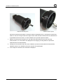
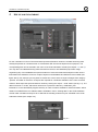
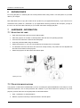
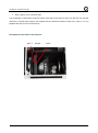
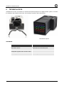
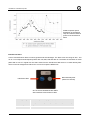
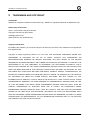
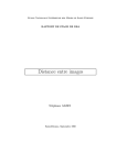
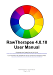
camSPECS User Manual 3. December 2014 Image Engineering GmbH & Co. KG · Augustinusstraße 9d · 50226 Frechen · Germany T +49 2234 9955950 · F +49 2234 995595-10 · www.image-engineering.de CONTENT 1 INTRODUCTION ....................................................................................................................................... 4 2 CAMSPECS HARDWARE ........................................................................................................................ 4 2.1 CAMSPECS - PROJECTOR SETUP......................................................................................................................4 2.1.1 Interference filters........................................................................................................................................... 4 2.2 CAMSPECS EXPRESS .........................................................................................................................................4 2.3 INSTALLING CAMSPECS - PC ......................................................................................................................4 2.4 INSTALLING CAMSPECS – MAC OS X ............................................................................................................5 3 WORKFLOW .............................................................................................................................................. 5 3.1 CAMSPECS.......................................................................................................................................................... 5 3.1.1 camSPECS settings .......................................................................................................................................... 5 3.1.2 Camera settings ................................................................................................................................................ 6 3.1.3 Camera position ............................................................................................................................................... 6 3.1.4 Exposure .............................................................................................................................................................. 7 3.1.5 Photographing the filters............................................................................................................................. 7 3.2 CAMSPECS EXPRESS .........................................................................................................................................7 3.2.1 camSPECS express settings ......................................................................................................................... 7 3.2.2 Camera settings ................................................................................................................................................ 7 3.2.3 Camera position and lenses used.............................................................................................................. 8 3.2.4 Exposure .............................................................................................................................................................. 8 3.3 SPECTRAL MEASUREMENT ...............................................................................................................................8 3.4 VALIDATION ........................................................................................................................................................9 3.5 CCM CALCULATION ...........................................................................................................................................9 3.6 CCM EVALUATION .............................................................................................................................................9 4 SOFTWARE DESCRIPTION ................................................................................................................ 11 4.1 GENERAL DESCRIPTION OF IMAGES ............................................................................................................. 11 4.1.1 Image data ........................................................................................................................................................ 11 4.1.2 Color filter array (Bayer pattern)..........................................................................................................11 4.2 SPECTRAL RESPONSE MODULE ..................................................................................................................... 13 4.2.1 Advanced settings ..........................................................................................................................................17 4.3 VALIDATION MODULE .................................................................................................................................... 20 4.4 COLOR CORRECTION MATRIX (CCM) CALCULATION MODULE ............................................................... 22 4.5 CCM EVALUATION MODULE .......................................................................................................................... 24 4.6 CALIBRATION................................................................................................................................................... 26 4.6.1 Calibration with camera ............................................................................................................................ 26 4.6.2 Calibration with spectrometer (camSPECS express) ....................................................................28 4.6.3 Calibration with spectrometer (camSPECS) .....................................................................................31 5 USE OF IN-SITU DATABASE .............................................................................................................. 34 6 KNOWN ISSUES ..................................................................................................................................... 35 7 HARDWARE - INFORMATION .......................................................................................................... 35 7.1 ADJUSTING THE LAMP .................................................................................................................................... 35 Image Engineering camSPECS 2 7.2 PROJECTOR MODIFICATIONS ......................................................................................................................... 35 8 TECHNICAL DATA ................................................................................................................................ 37 8.1 HARDWARE – CAMSPECS ............................................................................................................................. 38 8.2 HARDWARE – CAMSPECS EXPRESS ............................................................................................................ 40 8.3 SOFTWARE ....................................................................................................................................................... 42 9 TRADEMARK AND COPYRIGHT....................................................................................................... 43 Image Engineering camSPECS 3 camSPECS / camSPECS express 1 INTRODUCTION camSPECS consists of an illuminating hardware device and a software for evaluating images taken with a camera to measure its spectral sensitivity. Depending on the version there are two different hardware devices available. Both offer narrow-bandwidth spectra in the range from 380 to ~900 nm divided into 39 channels. The standard camSPECS uses sequentially displayed spectral channels. It contains a light source and a set of interference filters. camSPECS express is a different hardware device that allows the determination of the spectral response from one single shot. It consists of a box with a light source and a front plate with all interterference filters. Both versions also contain a spectromter for calibration and the evaluation software. The camSPECS software is an executable program for MS-Windows or Mac OSX and can be used for both hardware versions. 2 CAMSPECS HARDWARE 2.1 CAMSPECS - PROJECTOR SETUP 1. Remove the packaging material. 2. Check that the power supply voltage switch is set correctly to the voltage used in your country. The switch is located at the bottom of the projector. 2.1.1 INTERFERENCE FILTERS Put the inference filters into the slide magazine in the right order (0 - 40). The reference channel (ND filter) on each slide must be on the left side, when looking from the camera’s point of view. 2.2 CAMSPECS EXPRESS 1. Remove the packaging material. 2. The plug for the power supply and the main switch are located at the back side of the box. 3. The box contains a fan. Do not cover the fan-discharge duct on the right side of the box. 2.3 INSTALLING CAMSPECS - PC 1. Start setup_camspecs_win64.exe or setup_camspecs_win32.exe depending on your Windows operating system to install camSPECS software. Follow the instructions. During the installation process you are asked to select the spectrometer component to install. If you have a spectrometer for calibration, please select this option. 2. The latest Matlab Component Runtime is required for camSPECS. Execute MCRInstaller.exe (32 or 4 camSPECS / camSPECS express 64 bit) from the CD and follow the instructions. This will install the Matlab Component Runtime on your system, if necessary. 2.4 INSTALLING CAMSPECS – MAC OS X 1. Start setup_camspecs.dmg and follow the instructions. During the installation process you are asked to select the spectrometer component to install. If you have a spectrometer for calibration, please select this option. 2. Matlab Component Runtime is required for camSPECS. Execute MCRInstaller.dmg and follow the instructions. This will install the Matlab Component Runtime on your system, if necessary. 3. Run “camspecs.app” Only one Matlab Component Runtime can be installed on your Mac computer. camSPECS will not start if it is not in the applications folder. If you want to use it in a different folder: - Open program Automator - Drag and Drop the camspecs_V3.app onto the Automator Icon - Modify the path in the script that is displayed 3 WORKFLOW In this chapter the general workflow of spectral response measurements for both hardware solutions is described. For reliable measurements follow the tips in chapter 3.1 for the standard camSPECS device and chapter 3.2 for camSPECS express. Deviations from this procedure may result in wrong results. The chapters 3.3 to 3.6 describe briefly the workflow in all software modules. For detailed information of software usage read chapter 4. 3.1 CAMSPECS 3.1.1 CAMSPECS SETTINGS Turn the projector on and let it warm up for a couple of minutes. Put the slide magazine into the projector up to the stop. Bring the first filter into the projection slot by using the remote control. Always use the remote control for changing the slides, since doing this manually may result in a different position of the slide. Holding the green button on the remote control longer than 1s changes back to the last slide. Note: During the warm-up period the lamp may change its spectral behavior. 5 camSPECS / camSPECS express 3.1.2 CAMERA SETTINGS Set the camera to manual exposure mode. If a manual mode is not available, use the automatic exposure mode. To gain best results it is necessary, that the camera is able to save images as linear raw files. Recommended settings: Exposure program Manual Aperture Fix aperture when possible (same depth of field) ISO Speed lowest Auto focus off File type RAW 3.1.3 CAMERA POSITION Place the camera in front of the projector. Use the first filter slide to adjust the camera correctly. Take a picture of this slide and check if it displays the filters as follows: The interference filters are reflective, so stray light may affect the measurement. By bringing the filters out of center of the frame, a direct reflection of the reference channel on the sample channel can be avoided. Shield the camera with some dark cloth to block the room light. To avoid errors due to dust and the grid pattern of the reference filter slightly defocus the camera. 6 camSPECS / camSPECS express 3.1.4 EXPOSURE To get sufficient results the pictures of the filters may not be overexposed. To find an appropriate exposure insert the filter with the highest intensity (usually one of the filters from 530 – 560 nm). Take a picture of the filters with equal exposure settings. Ensure that the green channel has a high digital value without being saturated. One of the filters in this wavelength range should have the highest intensity in case of usual consumer cameras. When testing special cameras, like infrared cameras, one has to test possibly all filters to find out the brightest one. When using the auto exposure an exposure correction might be necessary. The evaluation software can use the camera's EXIF data or manually entered exposure data to correct the different exposure levels. Note: Reasonable starting values are t: 1/10 sec, f-stop: 5.6, ISO: 100 (= 8.3 EV). 3.1.5 PHOTOGRAPHING THE FILTERS Take pictures of the filters in series. Use the transportation system of the projector (green button on remote control) to change the filters. Do not change the order of the filters. Do not alter the position of the camera during one series of measurement. The supplied calibration data of the software will only work with all filters inserted. 3.2 CAMSPECS EXPRESS 3.2.1 CAMSPECS EXPRESS SETTINGS Switch camSPECS on and let it run for a couple of minutes until it reaches a stable temperature. Note: During the warm-up period the lamp may change its spectral behavior. 3.2.2 CAMERA SETTINGS Set the camera to manual exposure mode. If a manual mode is not available, use the automatic exposure mode. To get best results the camera shall be able to save pictures as linear raw files. Recommended settings Exposure program Manual Aperture No default value ISO Speed Lowest value Auto focus Off File type RAW 7 camSPECS / camSPECS express 3.2.3 CAMERA POSITION AND LENSES USED Place the camera in front of the filter plate. The principal axis of the lens shall be aligned perpendicular to the center of the filter plane. The distance between the lens and the filter plane depends on the focal length. The picture of the filter array shall cover all filters with some distance to the margins of the picture. Avoid using wide-angle lenses, since there is a slight angle dependence of the radiance power and the peak wavelength of the interference filters. Using lenses with higher focal distances ensures a minimum viewing angle - viewing angles below 15° do not cause noticeable impacts on the resulting spectral responses. Note: Ensure that the filters are the only light sources that are captured by the camera. To avoid stray light or other light hitting the camera sensor the pictures should be taken in a dark room or the space between camera and the camSPECS express box should be shielded. 3.2.4 EXPOSURE To get correct results the image of the filters may not be overexposed. Take a picture with reasonable exposure settings. Check the brightest filters for the highest intensity in all RGB channels. There shall be no filter saturated in one of the channels. Choose exposure values so that there is no saturated RGB channel in any filter and that at the same time the brightest channel has a reasonably high digital value. 3.3 SPECTRAL MEASUREMENT Start the camSPECS software and switch to module Spectral response. Check the advanced settings menu (see chapter 4.2) for the default values to comply with your needs. Add the master calibration file delivered on the CD. You may add and delete files from the menu using the corresponding buttons. Calibration files created with the software itself are automatically added to this menu. Check all other settings to comply with your needs (e.g. 'use EXIF data' or choose a dark image). Select and add images with the '+' button. Click the Start button. Check the result of the automatic detection and confirm by double clicking on the image outside the displayed Regions Of Interest (ROI). The rectangles may be rearranged here if necessary. The result of the measurement is displayed and a text file with the name of the first image (camSPECS) or the name of the image (camSPECS express) is saved to the same directory as the images. For documentation purposes the spectral curves can be saved as an image file. See detailed information on this module in chapter 4.2. 8 camSPECS / camSPECS express 3.4 VALIDATION Take a picture of a ColorChecker (24 patches or SG) chart that was illuminated by a light source whose spectral distribution is incorporated in the software. You can add your own spectral distribution file to camSPECS. (see item 1 in chapter 4.3 ) The picture shall have uncompressed RGB data (e.g. TIFF format). Switch to module Validation and choose a spectral response. Select the light source and reflectance data from the drop-down menus for the respective ColorChecker. Select the image of the ColorChecker chart (RGB of Bay-pattern TIFF image). Select optionally a dark frame for correction. Click the Start button and draw a rectangle around the patches in the displayed image. Double click on the image and check in the next step the positions of the ROIs. You may correct their positions by dragging and dropping them with the mouse before clicking on the image outside the ROIs to continue. The graph displays the measured RGB values for each patch plotted against the predicted values in normalized values (from 0...1). For documentation purposes the graph can be saved as an image file. See detailed information on this module in chapter 4.3. 3.5 CCM CALCULATION Select the spectral data of a light source, the ColorChecker training data and a measured spectral response file in the corresponding menus and input fields. Choose whether you want to apply white balancing to the calculation of the matrices. Enter the camera settings. (The values are only used by the CIECAM02 algorithm.) Click Start and six matrices are calculated and displayed. Optionally the white balance multipliers are displayed. You can save all matrices to a plain text (.txt) or XML file by clicking on the Save matrices button. See detailed information on this module in chapter 4.4. 3.6 CCM EVALUATION With this new module the (sRGB) matrices can be applied to real images. Open a RGB image that was converted from a raw camera file without any modifications concerning gamma, color, contrast or any other correction. Only the demosaicing step should be applied. Images bigger than the size of the display window in camSPECS are scaled to maintain rapid display of the corrected image. Select a matrix file (in XML format), that was saved from the CCM calculation module. The sRGB matrices are used in this case for the correction. Select one of the matrices to calculate and display the corrected image. 9 camSPECS / camSPECS express Optionally a gamma correction (based on sRGB) can be applied to both images for better comparison. With the editable free matrix fields you can adjust your own matrix. Use one of the three calculated matrices as a starting matrix by copying it to the edit fields with the Copy (>>) button. Save the free matrix (including all others) to a new plain text or XML file. The exported XML file may be loaded again in this module. For documentation purposes the images and the matrices can be saved to an image file. See detailed information on this module in chapter 4.5. 10 camSPECS / camSPECS express 4 SOFTWARE DESCRIPTION With the camSPECS software you have a powerful tool to measure the spectral sensitivities for both hardware versions. The results may be used for comparison or documentation purposes and can be used for the calculation of Color Correction Matrices (CCM), which might be incorporated into cameras. The results can be saved in form of plain text (.txt) or XML files. For fast documentation purposes the resulting plots and images can be saved to images (JPEG, PNG, TIFF, BMP, GIF). The software allows for a validation of the measurement setup with well-known reference data (based on ColorChecker charts) and a recalibration of the hardware with the incorporated monochrome camera. The CCM modules include also the measurement of the white balancing multipliers of the camera and a quality index for the metamerism of the camera. The matrices can be evaluated by applying them to real images. 4.1 GENERAL DESCRIPTION OF IMAGES This section describes the general specifications for the images to measure. 4.1.1 IMAGE DATA The camSPECS software can handle demosaiced images or images with the original CFA independent from the file type. If you use your own raw image converting software you should convert the images to TIFF files by maintaining the Bayer pattern. You can also use the program dcraw to convert D-SLR camera raw files the latest release is delivered with camSPECS. Mac OS X and Windows® versions are available. If you do not have access to raw files camSPECS can handle RGB images. If raw files are selected the raw processing is performed automatically for all images selected in every module. The files are saved as TIFF files to a sub-directory named “converted” at the location of the original files. These images are used for the subsequent processing. If further tests with images shall be accomplished you can choose the converted images for faster processing. Images are converted retaining the original Bayer pattern. Note: See www.cybercom.net/~dcoffin/dcraw/ for list of all supported cameras. On this site you will also find a link to the latest executable version of dcraw. To update dcraw just replace the dcraw.exe with the new one in the “app” directory of the camSPECS program directory. Or choose dcraw from a different location on your disk in the advanced settings. 4.1.2 COLOR FILTER ARRAY (BAYER PATTERN) 11 camSPECS / camSPECS express Sometimes it might be necessary to set the CFA manually (see 4.2.1). To figure out how the pixels are located in the CFA open the images of the filters 450nm, 550nm and 650nm (projector version) with an image processing software (e.g.: ImageJ). Or look at the corresponding filters in an image taken with camSPECS express. These filters represent blue, green and red. (Non-standard color filter arrays are supported since version 2.8: you can select 'C' (for Clear) for each channel in the drop-down menus in the advanced settings. (see chapter 4.2.1) If you have a close look at the CFA in the 450 nm picture, the brightest pixel is blue. The brightest pixel in the 650 nm filter picture is red. The remaining two pixels of a 2x2 area represent the green channel of the camera. This procedure should work with most regular 3-channel cameras. The camSPECS software always uses odd pixel positions to avoid mixing up the color channels. 12 camSPECS / camSPECS express 4.2 SPECTRAL RESPONSE MODULE Description of the numbered controls marked in the image above: 1. Select the calibration file for your camSPECS or camSPECS express hardware. With the '+' and '-' buttons calibration files can be added and removed from the list. The selected calibration file in the menu must correspond to the images selected. If a camSPECS calibration file is selected the program expects a corresponding number of camSPECS images in the image list. That means that there must be as many images as there are rows in the calibration file. The calibration files are located in the directory /calibration_files/filter of the camSPECS program folder. Wavelength (nm) Power of color filters Power of neutral density filters 380 49.1 1316 390 110.7 1286 400 181.7 1287 410 208.3 1295 … … … 700 297.6 1308 13 camSPECS / camSPECS express 710 321 1283 720 286 1294 750 1345 1289 800 1076 1310 850 996 1312 905 408 12 Table 1: Formatting of the calibration file for camSPECS Wavelength (nm) of the color filters, ‘1’ denotes the ND filters Power of the filters 377 0.1933 1 0.1009 386 0.1629 1 0.1219 … … 846 0.0829 1 0.1681 895 0.0604 1 0.1094 Table 2: Formatting of the calibration file for camSPECS express: the rows contain values for the wavelength and the power of the color filters and the ND filters alternating from line to line. “1” stands for the ND filter. The corresponding filters on the panel are numbered from the upper left corner to the lower right corner (see figure 1). * Center filter arrangement, two subsequent neutral filters (see figure 1) 2. Use the reference channels (neutral density filters) to correct for exposure differences. Note: The neutral density (ND) filters adjacent to the interference filters are used as a brightness reference for correction of different exposure levels. Such differences may be caused by using automatic exposure control or imprecise working shutter or aperture control of the camera in case of camSPECS. For camSPECS express remaining inhomogeneities of the irradiation device are corrected by the nearest neighbor ND filters. 3. Use EXIF data for correction of different exposure settings. This is necessary when the automatic exposure control of the camera is used. 4. Apply dark frame subtraction. Supported image types are: TIFF, PGM, BMP, PNG, PPM and raw files. Take an image with the same camera exposure settings as used for the camSPECS images. It will be subtracted from each image in the processing list. This option is used to subtract the offset value, inherent in all images, that has its origin in the dark current of the sensor. This offset value has a negative impact on the spectral measurement. 5. Set the maximum allowed digital value. If this value is exceeded in an image, an error message is displayed. This value depends on the bit depth of the images. For example, if your image has a bit depth of 16 (= maximum digital value of 65535) you may prevent images being processed that have 14 camSPECS / camSPECS express values above 65000. 6. Add image(s) to processing list. Supported image types are: TIFF, PGM, BMP, PNG, PPM and raw files (The term "raw file" means files that are created by a digital camera in "RAW-Mode" and are readable by the software dcraw. This does not include raw files that do not follow any image file format. You should convert these files to 16-bit Tiff images first.). Depending on the selected calibration file (see item 1) you can choose one or more images that must contain the filter arrangement either of camSPECS express or camSPECS. With the '+', '-' and 'C' buttons you can add images, remove one selected image or clear the whole list. After the measurement the spectral curve of the first image in the list is displayed. By clicking on the other images in the list the corresponding results are displayed. 7. Check the advanced settings (chapter 4.2.1). 8. Starts the processing procedure. In both versions camSPECS and camSPECS express, the filters in the images are detected automatically or manually (chapter 4.2.1). After the detection process a confirm dialog is shown where the ROIs for each filter can be manually repositioned if necessary (figure 4.2.1). By double-clicking on the background the processing starts. The resulting spectral curves are displayed and saved to a plain text (.txt) and a XML file in the same directory as the original image directory. For the camSPECS version a tile image is saved to the same directory as the origin of the images directory (figure 4.2.2), assembled from all images. Check this image for correct positions of the ROIs or all filters. 9. When the measurement is done you can switch between raw and normalized RGB spectral curves data. 10. Export the spectral curves to an image (JPEG, PNG, TIFF, BMP, GIF) for documentation purposes. 15 camSPECS / camSPECS express Figure 4.2.2: A tile image is created from all images of a series. Displaced filter frames can be identified easily. 16 camSPECS / camSPECS express 4.2.1 ADVANCED SETTINGS 1. The software detects the Color Filter Array (CFA) automatically by default. Choose option Manual to set the color filter array freely. If there is a CFA that is not a standard pattern, for example special cameras without a filter for one channel, C (Clear) can be chosen. In this case all four channels are measured separately and displayed as four different channels without any assignment to a color. 17 camSPECS / camSPECS express 2. This is the default option for the display and export of the curves. Both green channels are averaged. 3. With this option all four channels of the CFA are displayed and exported separated. 4. Use decimal comma in the resulting text and XML file. 5. Interpolates the spectral response data to increments of 5 nm. Default value is 10 nm if this option is not selected. 5 nm graded values are necessary for further processing in the modules Validation and CCM calculation. 6. Size of the ROI for the measurement of digital values in every filter in relation to the diameter of the filter. Standard value is 70%. Selecting higher values may result in inaccurate results due to vignetting artifacts of the filters near the borders. The minimum size is limited by the amount of pixels inside the ROI. For statistical significance more than 100 pixels are needed; if the number falls below this value the program gives a warning. The measurement is nevertheless continued. 7. Select the dcraw application (see note below). By default the dcraw version delivered with the software is used. It is located in the directory “app” inside the camSPECS program directory. The raw image processing camSPECS uses dcraw to convert common camera raw files to TIFF files. The converted images are saved to a sub-directory named 'converted'. Note: A long file path or a network path can cause problems using dcraw. Try to use short paths. (For example: C:\program files\dcraw). See www.cybercom.net/~dcoffin/dcraw/ for a list of all supported cameras and for the current version of dcraw. 8. Choose the detection mode for the filters in camSPECS express images: - Automatic detection: Several camSPECS express images can be measured subsequently without interruption. Failed detections are ignored in this case. - Semi-automatic detection: Each spectral measurement is interrupted by a dialog for controlling the ROI locations of the filters. The preceding filter detection itself is however automatic. The ROIs can be activated and aligned with the mouse. Semi-automatic detection of the filters in camSPECS and camSPECS express. The ROIs shown in this example were set to a size of 50% (left), respectively 70% (right) of the diameter of the corresponding filters. 18 camSPECS / camSPECS express - Manual detection: Each spectral measurement is interrupted by a dialog for manual detection of the filters. Use this option if the automatic detection fails. Reasons for failing are mostly images exposed with wide-angle lenses or images with artefacts that are caused by stray light during shooting. Use the four sliders to limit the characteristics of the neutral density filters. Compare the detection in your image (left side) to the nominal positions of the filters. If the correct number of filters of 40 is found you are able to continue by clicking the OK button. 19 camSPECS / camSPECS express 4.3 VALIDATION MODULE 1. Select a spectral response text (.txt) file with values interpolated to 5nm (see advanced settings), that was created by camSPECS. 2. Select a spectral distribution for the light source used for the illumination of the ColorChecker test chart. Individual light sources may be used here. To create an individual light source file, intensity values for wavelengths between 380 and 780 nm in 5 nm steps are needed. Put this data into a text file with the wavelength values in the first column and the intensity values in the second column. Columns must be separated with a tabulator. The files in the /calibration_files/lightsource directory of the camSPECS program folder may be used as a template. Format your file corresponding to these files and copy it to this folder, restart camSPECS. Wavelength (nm) Intensity 380 24.49 385 27.18 390 29.87 … … 770 82.92 775 80.6 780 78.27 Table 3: Formatting of the light source files in a sample from the D50.txt file. 20 camSPECS / camSPECS express 3. Select ColorChecker reflectance data. The data used contains the spectral distribution between 380nm and 730nm in 5-nm increments. 4. Select an RGB image file of a ColorChecker test chart (ColorChecker with 24 patches or ColorChecker SG with 140 patches). The image may not be a raw image file. Do not use compressed image formats like JPEG since colors may differ too much. Not manipulated TIFF images, converted from raw camera files, are the best choice. 5. Select optionally a dark image for subtracting from the ColorChecker image. The size of this image and the ColorChecker image must be the same. The image may not be a raw image file. 6. After clicking the Start button the selected ColorChecker image is opened and displayed. You can select the color chart by drawing a rectangle around the patches from upper left to lower right and double click on the rectangle. The ROIs for each patch are displayed in the next step and can be rearranged manually. Double click outside ROIs to continue. 7. Export the validation graph to an image (JPEG, PNG, TIFF, BMP, GIF) for documentation purposes. The validation proves the processing chain from the exposure of the ColorChecker images (surrounding light conditions, camera lenses, raw image converting, etc.) to the measurement of the spectral response with camSPECS. In the displayed result the measured digital values (red, green and blue) for each patch are plotted against the predicted digital values. All values are normalized to a range between 0 and 1. If the exposure and measurement setup is highly accurate all RGB data points in this plot should be close to the white diagonal line (best correlation). Possible reasons for major variations may be changes in the illumination of the ColorChecker, or in manipulations of the RGB data within the camera. Fig. 4.3.1 Fig. 4.3.2 21 camSPECS / camSPECS express 4.4 COLOR CORRECTION MATRIX (CCM) CALCULATION MODULE 1. Select a spectral distribution file for the light source used for the illumination of the ColorChecker chart. For individual light sources see chapter 4.3, item 2. 2. Select a spectral response text (.txt) file with values interpolated to 5nm (see advanced settings), that was created by camSPECS. 3. Select training reflectance data. The data used contain the spectral distribution between 380nm and 730nm in 5-nm increments. Other than ColorChecker data can be used, for example like iQ in-situ data (chapter 5). New files can be added to the corresponding directory in the camSPECS software (/calibration_files/reflectance). Restart camSPECS in order to use the new files in this menu. 4. With this option the white balance multipliers are calculated from simulated constant reflectance values, the illuminating light and the camera spectral sensitivities. 5. For the CIECAM02 matrix the camera settings may be used by the algorithm for the calculation of the luminance. Enter ISO speed, shutter speed, F-stop and the exposure compensation. 6. The resulting matrices can be exported as a plain text or XML file. The columns are tabulator separated. 22 camSPECS / camSPECS express Three different algorithms for calculating the matrices are incorporated: Least-squares linear regression (LS): With this method the overall residual squared error is minimized. It makes no statement about which colors will be mapped well and which will be mapped poorly. White-point preserving least-squares (WPPLS): This method preserves the achromatic (white and gray scale) colors. It may deliver poorer color correction compared with the LS procedure, but squared error need not necessarily correlate with perceived visual error. This procedure is described in: Graham D. Finlayson and Mark S. Drew. White-point preserving color correction, The Fifth Color Imaging Conference: Color Science, 1997. CIECAM02: The CIECAM02 color appearance model is based on CIECAM97s and was published in 2002 by the CIE Technical Committee 8-0 (Nathan Moroney et al. The CICAM02 Color Appearance Model, IS&T/SID Tenth Color Imaging Conference). It includes revisions and simplifications of the transforms of the CIECAM97s model. Additional measurement of DSC/SMI (Digital Still Camera / Sensitivity Metamerism Index): DSC/SMI is designed to give a measure for potential color errors caused by real cameras reproducing different sensor outputs for two objects having the same tristimulus values but different spectral distributions. The implemented Average DSC/SMI will give a measure of camera metamerism for ordinary reflective objects. In this definition eight color patches represent reflective objects. The index ranges from 0 to 100 (best). Reference: ISO 17321-1:2006 (E), International Imaging Industry Association (I3A), 701 Westchester Avenue, Suite 317W, White Plains, NY 10604 USA. Note: The selected training data and the camera settings are not used for calculation of the DSC/SMI, the spectral data of the eight color patches are implemented permanently in the program. 23 camSPECS / camSPECS express 4.5 CCM EVALUATION MODULE 1. Load a sample image in camera RAW format. Big images are scaled down to fit into display and for fast processing. 2. Load an XML file with the matrix data, which was exported in the CCM calculation module. 3. Choose one of the three matrices in order to apply it to the image. 4. A gamma correction conforming to the sRGB standard can be applied to the image additionally in order to improve evaluation. 5. Clicking this button copies the values of the selected matrix to the custom matrix fields. 6. Apply the custom matrix to the image. You can adjust all matrix entries for your own needs. To support easy control you may use the following shortcuts, after clicking into one of the fields: Use the up-/ or down-arrow for changing the values in the following way: ◦ Up-/down-arrow: ± 1.0 ◦ Shift key + up-/down-arrow: ± 0.1 ◦ CTRL key + up-/down-arrow: ±0.01 ◦ ALT key + up-/down-arrow: ± 0.0001 The sum of the values in the rows of the matrix is displayed, this value should be 1.0000. Click 'Enter ' to confirm change. 24 camSPECS / camSPECS express 1 0 0 7. Reset all matrix values to identity matrix: 0 1 0 0 0 1 8. Export all matrices including the custom matrix to plain text (.txt) or XML file. The XML file can be loaded again in this module (see item 2.). 9. Export both images and the matrix applied to one assembled image for documentation purposes. JPEG, PNG, TIFF, BMP, or GIF format. 25 camSPECS / camSPECS express 4.6 CALIBRATION Due to changes of the radiation characteristics of the lamps over time or after replacement of a damaged lamp a calibration is advisable. Since the lamps in standard camSPECS and camSPECS express change their spectral distribution during lifetime a calibration should be carried out periodically. Older versions of camSPECS were delivered with a monochrome camera for this purpose, current versions (since 2013) include a spectrometer EX1. While the calibration with the monochrome camera is based on a relative measurement the spectrometer calibration is absolute. Customers who have a standard camSPECS device with an extended IR range for the filters can use the EX1 up to 820 nm and calibrate the IR filters with their own (IR-sensitive) camera. Each camSPECS device is calibrated before delivery. The calibration file can be found on the installation CD. Note: The spectrometer EX1 has a spectral range from 350 to 820 nm. Thus the filters from 380 to 800 nm can be measured. The calibration values for the filters 850 and 905 nm (express) and all other IR filters (extended filter set for standard camSPECS) are interpolated using the calibration values from the original calibration file. The initial calibration for each camSPECS device is performed at Image Engineering with an laboratory spectrometer. If you have a camera with IR sensitivity a more accurate calibration is possible in this range. You may use your own camera as a calibration device, if the camera is sent to Image Engineering for calibration. 4.6.1 CALIBRATION WITH CAMERA With the monochrome camera delivered with your camSPECS hardware, you can perform a relative calibration. The first version of camSPECS was delivered with a monochrome camera and a reference spectral measurement with this camera. The relative calibration consists of a comparison of a current 26 camSPECS / camSPECS express spectral measurement with the reference spectral measurement. The original calibration file (delivered with the CD) is then corrected with the comparison result. A new calibration file is generated and made available. The reference measurement file can be found in the directory “Intensity calibration file” on the CD (the name of the file has the form: Calibration_set##_dd-mm-yyyy.txt). Description of the numbered controls marked in the image above: 1. Perform a spectral measurement with the monochrome camera or your own camera that was initially calibrated at Image Engineering. Select a currently measured spectral response. 2. Select the reference spectral response file. 3. Select the reference calibration file for your camSPECS device. 4. When the option Calibrate IR range (> 800 nm) is activated only the calibration factors outside the visible range are corrected. This only affects the standard camSPECS device and not the express edition. Reasons for calibrating only the IR range with the camera is mainly the following scenario: You have a camera which is IR sensitive and you have the standard camSPECS device with extended filter set. With the spectrometer you are capable of performing an absolute calibration with the spectrometer in the range from 380 to 800 nm as a first step. For calibrating the IR range use the camera delivered with camSPECS or your own camera that was initially calibrated at Image Engineering. As a second step perform a relative calibration with this camera. Make a spectral measurement with the camera and select the resulting measurement file as described in item 1. Select the reference file as described in item 2. Choose the calibration file that you have created with the absolute calibration procedure described in chapter 4.6.3. Activate this option [4] and continue with item 5. 5. Click button Compare files to display the spectral sensitivities of the current measurement and of the reference measurement. 6. The button On-site recalibration displays both spectral sensitivity curves and additionally calculates a new calibration file which is now available in the menu Calibration file in the Spectral response module. The file name contains the date and time of the recalibration: “Camera_calibration_set_ddmm-yyyy_hh-mm-ss”. To validate the recalibration process you can run a new spectral response measurement (with the same images), switch to the recalibration module and compare the new result file to the reference file. Both curves are now supposed to have the same progression. 7. For documentation purposes the spectral curves can be saved as an image file. 27 camSPECS / camSPECS express 4.6.2 CALIBRATION WITH SPECTROMETER (CAMSPECS EXPRESS) Since version 3.0 of camSPECS a micro spectrometer EX1 is delivered with the camSPECS express hardware as a calibration tool. Also included is a positioning guide for the EX1, which is a metal plate that can be placed easily in front of the filters. Mount it in such a way, that the “missing” filter (see image below) is at the bottom right. There is no filter at this position on the front side of camSPECS. Unscrew the knob in the middle, so that the spectrometer head can be inserted in the surrounding holes. During measurement insert the spectrometer head in each hole of the plate until it reaches the stop. Now plug the spectrometer with the USB cable to the computer and switch to the Calibration module. If the spectrometer component was installed the spectrometer is recognized and the radio button “Calibration with spectrometer” is selectable. The calibration procedure should be carried out in a dark place and requires approximately 20 minutes. In the order of the filters to be measured comes first a dark measurement, then all color filters from upper left to lower right and finally all neutral density filters from upper left to lower right. The result of each measurement is displayed, that is: the spectral distribution from 350 to 820 nm, the center wavelength of the peak and the calibration value. The calibration value is the area under curve (AUC) in the 28 camSPECS / camSPECS express interval, where the lower and upper limits are specified at the 10 % threshold of the maximum. A failed measurement may be repeated, e.g. in case a wrong filter was measured. The next filter which is next in line is highlighted in the image of the camSPECS filter matrix [8]. After the measurement procedure is finished a new calibration file is created and is immediately available in the spectral response module. Positioning plate for EX1 Description of the numbered controls marked in the overview image of this chapter: 1. Click the button Search spectrometer to scan USB devices for an attached spectrometer. In some cases it is necessary to disconnect and connect the spectrometer from the computer and then to search again. Note: In very rare cases the spectrometer may hang. This might lead to a crash of the application in consequence. “Restart” the spectrometer by plugging it off from the computer in order to interrupt power supply. Connect it again and click Search spectrometer. 2. If a connected spectrometer is available for measurement some information is displayed here: the serial number and the firmware version. The integration time denotes the time for one filter measurement. This value cannot be changed. 3. In this editing field a name for the final calibration file can be edited, it has by default the form “Calibration_Spectrometer_” plus the current date. You may want to change the name for your own needs here. This name is used for the display in the spectral response module in the menu Calibration file (chapter 4.2). 4. Put the covering cap onto the aperture of the spectrometer. With the start button the calibration procedure is started with a dark measurement. The result is displayed in the graph. It is important that the cap fully covers the aperture during the measuring time, since the dark measurement is subtracted from each following filter measurement for noise reduction. A dark measurement must exhibit a constant value over the whole wavelength range with some noise like in the sample below: 29 camSPECS / camSPECS express After the dark measurement is finished all color filters have to be measured. Remove the cap from the aperture of the spectrometer and measure the filters that are highlighted in the image [8]. 5. Place the spectrometer head in the upper left hole, the first filter to be measured. Click button Measure. Check the result in the graph: The center wavelength calculated may differ from the nominal value, generally not more than ± 3 nm. The nominal value for the current filter is also displayed right beneath the overview image [8]. All filters from 380 to 720 nm exhibit a narrow bandwidth behavior, while the filters 750 and 800 nm have a much broader bandwidth (see graph in chapter 8.1). If you are not satisfied with the result you may want to repeat the measurement click button Repeat. Only the last measurement can be repeated. Please note that the filters 850 and 905 nm are omitted in the calibration procedure. Continue measuring all ND filters. Finally the calibration file is generated and saved to disk. It is now available in the spectral response module. 6. This button repeats the last measurement. Always check the resulting graph and center wavelength after each measurement for reliable results and repeat only if you are not satisfied with the result, mostly in case of slipping of the spectrometer head during a measurement. 7. Clicking the Cancel button stops the whole calibration procedure and discards all measured filter calibration values. The calibration procedure needs to be started again. 8. In the image the next filter to be measured is displayed. 30 camSPECS / camSPECS express 4.6.3 CALIBRATION WITH SPECTROMETER (CAMSPECS) Description of the numbered controls marked in the image above: 1. Click the button Search spectrometer to scan USB devices for an attached spectrometer. In some cases it is necessary to disconnect and connect the spectrometer from the computer and then to search again. Note: In very rare cases the spectrometer may hang. This might lead to a crash of the application in consequence. “Restart” the spectrometer by plugging it off from the computer in order to interrupt power supply. Connect it again and click Search spectrometer. 2. If a connected spectrometer is available for measurement some information is displayed here: the serial number and the firmware version. The integration time denotes the time for one filter measurement. This value cannot be changed. 3. In this editing field a name for the final calibration file can be edited, it has by default the form “Calibration_Spectrometer_” plus the current date. You may want to change the name for your own needs here. This name is used for the display in the spectral response module in the menu Calibration file (chapter 4.2). 4. In this menu all available calibration files for standard camSPECS device are selectable. A current calibration file is needed since the calibration values for the 850 and 905 nm filter are interpolated from the selected file. 31 camSPECS / camSPECS express 5. Put the covering cap onto the aperture of the spectrometer. With the start button the calibration procedure is started with a dark measurement. The result is displayed in the graph. It is important that the cap fully covers the aperture during the measuring time, since the dark measurement is subtracted from each following filter measurement for noise reduction. A dark measurement must exhibit a constant value over the whole wavelength range with some noise like in the sample below: After the dark measurement is finished all color filters have to be measured. Remove the cap from the aperture of the spectrometer and measure the filters that are highlighted in the image [8]. 6. Place the calibration tube with the optical fibre in the front opening of the projector. Align the marker for color filters on the tube (see images below) with the triangle marker on the projector. Screw the patch cord onto the connector of the spectrometer and the other end of the patch cord onto the connector of the tube. The calibration tube positioned for measuring the color filters The fibre patch cord (SMA 905 type) Click button Measure. Check the result in the graph: The center wavelength calculated may differ from the nominal value, generally not more than ± 3 nm. The nominal value for the current filter is also displayed right beneath the overview image [8]. All filters from 380 to 720 nm exhibit a narrow bandwidth behavior, while the filters 750 and 800 nm have a much broader bandwidth (see graph in chapter 8.1). 32 camSPECS / camSPECS express Marker for color filter position Marker for ND filter position Continue measuring the ND filters. Therefore rotate the calibration tube by 180 degrees until the ND marker on the tube is aligned with the triangle marker. After last filter measurement the calibration file is generated and saved to disk. It is then available in the spectral response module. 7. With the next and previous buttons you may skip back and forward from the first to the last measured filter. The current filters are displayed in the image [9]. Clicking Measure repeats the measurement for the selected filter. 8. Clicking the Cancel button stops the whole calibration procedure and discards all measured filter calibration values. The calibration procedure needs to be started again. 9. In the image the next filter to be measured is displayed. 33 camSPECS / camSPECS express 5 USE OF IN-SITU DATABASE For the calculation of a Color Correction Matrix spectral reflectance values are needed as training data. Usually the patches of a ColorChecker or ColorChecker SG are used as objects for this purpose. The corresponding files can be selected in the menu of the CCM calculation module (see chapter 4.4, item 3). You may also use individual training data received from the iQ in-situ database (http://insitu.imageengineering.de). In this database the spectral radiance of more than 2000 natural objects under various illuminations are available. Choose a couple of objects in the database and add them to the basket (see figure above). For example you may want to choose skin colors, select a couple of images from category “portrait”. A number of more than 10 objects are required for a sufficient estimation of the color correction matrices. Now export the spectral radiance values by clicking the “export → both” button (see fig. 5.1). The data is saved as a .csv file, which then needs to be copied to the directory “/calibration_files /reflectance” in the camSPECS program directory in order to make it available for CCM calculation. After a restart of camSPECS the new radiance data is available in menu “Training data” in the CCM calculation module. After calculation and export to an XML file the resulting matrices may be evaluated in the CCM evaluation module (see chapter 4.5). Fig. 5.1 34 camSPECS / camSPECS express 6 KNOWN ISSUES PC: A long file-path or a network path can cause problems when using 'dcraw'. Use short paths on your hard disk for your images. Mac OSX: Make sure to copy the content of the .zip file into your applications directory. If you need to run it somewhere else, please run „Automator“ (in you applications directory) and drop the camspecs_V2.app on the icon. You can now edit the directory to your needs. Save after changing the path. 7 HARDWARE - INFORMATION 7.1 ADJUSTING THE LAMP Open the lamp housing and remove the diffuser plate. Place the projector on its back in vertical position with the lens hole pointing upwards. Cover the lens hole with a sheet of thin white paper. Insert the perforated slide using the slide lift. Switch the projector on. You can see the filament of the lamp twice on the paper. The filaments must have the same size and must overlap exactly. The position can be adjusted with the knobs at the bottom of the projector. Switch the projector off and reinsert the diffuser plate. Adjusting the lamp 7.2 PROJECTOR MODIFICATIONS The projector contains three modified filters, one for converting the spectral distribution of the lamp to a more continuous spectrum, one for heat protection and a diffusor. If you remove filters for cleaning or any other purpose, put them back into the original position as described below: 1. Filter 1 (colorless), for heat absorption 2. Diffusor, improves uniformity of the illumination in the filter plane 35 camSPECS / camSPECS express 3. Filter 2 (blue), color conversion filter The combination of both filters model the output of the light in the range of 350 nm to 950 nm in a way that reduces the contrast ratio between the brightest and the darkest interference filter from 1:300 to 1:8. The brightest filter is thus the one with 540 nm. Arrangement of the filters in the projector Filter 2 Diffusor Filter 1 36 camSPECS / camSPECS express 8 TECHNICAL DATA camSPECS is an all in one solution to measure the spectral response of a digital camera system. It contains the hardware and software tools which are necessary to perform the measurement. camSPECS camSPECS express HARDWARE camSPECS camSPECS express Illumination device Illumination box with filter panel A set of interference filters mounted in a small plate together with a reference filter A micro spectrometer for calibration A micro spectrometer for calibration 37 camSPECS / camSPECS express 8.1 HARDWARE – CAMSPECS Illumination The illumination system is a customized slide projector with a stabilized light source. Due to the stabilization of the power supply the spectral distribution of the light source is not affected by fluctuations of current. The slide transportation system of the projector is used to move the filters subsequently into the light path. Instead of the lens, a tube lined with black cloth to reduce stray light, is used. The camera to be tested is mounted directly in front of the projector and photographs the interference filters. Light source Halogen (24V / 55W) JCD24V55WDX Durability of light source 1000 h Voltage supply Adjustable 100-230 V, 50-60 Hz Stabilization factor 1% Power input Approx. 150 W Dimensions (w / h / d) 291 x 136 x 304 mm Weight 6 kg Distance filters to leading edge of the device 12.5 cm Relative spectral power distribution of lamp and relative transmittance of the filters 38 camSPECS / camSPECS express Relative spectral power distribution of the filtered lamp and relative radiance power of the interference filters Interference filters A set of 39 interference filters is used to generate narrow-band light. The filters cover the range of 380 - 720 nm in 10 nm steps and subsequently filters with 750, 800, 850 and 905 nm. The filters are mounted on metal plates with a size of a regular 35 mm slide. Aside from the interference filter there is a neutral density filter which is used as a brightness reference to correct for exposure differences. Neutral density filter (reference channel) interference filter One of the 39 camSPECS filter slides with interference and reference filter Wavelength range 380 - 720 nm (10 nm steps), 750, 800, 850 and 905 nm Bandwidth 10 nm (380 - 720 nm), 40 nm (750 nm), 50 nm (800 - 905 nm) Off band rejection 4.0 optical densities Diameter 12.5 mm 39 camSPECS / camSPECS express Relative radiance power of the interference filters 8.2 HARDWARE – CAMSPECS EXPRESS Illumination The illumination system of the camSPECS express box contains a stabilized light source. Due to the stabilization of the power supply the spectral distribution of the light source is not affected by fluctuations of current. Light source Halogen (24V / 250 W), Osram 64655 EHJ Durability of light source 50 h Color temperature 3550 K Luminous flux 10.000 lm Voltage supply Automatic adjustable 110 – 230 V, 50-60 Hz Stabilization factor 1% Power input Approx. 300 W Dimensions (w / h / d) 295 x 295 x 540 mm Weight 7 kg 40 camSPECS / camSPECS express Filter panel A set of 39 interference filters is used to generate narrow-band light. The filters cover the range of 380 – 720 nm in 10 nm steps and subsequently filters with 750, 800, 850 and 905 nm. The filters are mounted on the front plate of the camSPECS express box. The arrangement of the filters can be seen on the following figure: the series start with 380 nm on the upper left side and continue line by line to 905 nm. In between located are the ND filters. Interference filter (380 nm) ND filters Interference filter (905 nm) Wavelength range 380 - 720 nm (10 nm steps), 750, 800, 850 and 905 nm Bandwidth 10 nm (380 - 720 nm), 40 nm (750 nm), 50 nm (800 - 905 nm) Off band rejection 4.0 optical densities Diameter interference filters 12.5 mm Diameter ND filters 8 mm 41 camSPECS / camSPECS express 8.3 SOFTWARE © The evaluation software is a Matlab based Windows or Mac OS X program. To run the program the Matlab Component Runtime (MCR) is necessary. The MCR is distributed together with the software. System Requirements Microsoft® (32bit and 64bit) Mac Operating Systems Windows® Vista Service Pack 1 or 2 Windows® 7 Mac OS X 10.7.x (Lion) and above Processors Intel® Pentium® 4 and above Intel® Celeron®** Intel® XeonIntel® Core Intel® Atom®** AMD Athlon 64** AMD Opteron AMD Sempron** All Intel-based Macs RAM 2048 MB (4096 MB recommended) 2048 MB (4096 MB recommended) RAW file conversion camSPECS uses dcraw to convert common camera raw images to TIFF images. You can find a list of all supported cameras at: www.cybercom.net/~dcoffin/dcraw/ Standard processing is the conversion to linear TIFF files while retaining the CFA pattern. To suppress fixed pattern noise a dark frame subtraction (DFS) can be performed. The DFS can be performed with already converted files. Supported file types are: .tiff, .bmp, .pgm, .ppm, .png. dcraw is also able to read the EXIF data from the images like shutter speed, f-stop and ISO speed. 42 camSPECS / camSPECS express 9 TRADEMARK AND COPYRIGHT Trademarks Windows is a registered trademark of Microsoft Corp., Matlab is a registered trademark of Mathworks Corp. Software by Third Parties dcraw -- Dave Coffin's raw photo decoder Copyright 1997-2010 by Dave Coffin [email protected] (www.cybercom.net/~dcoffin/dcraw/) Copyright Information By installing this software, you accept and agree to be bound by the terms of the software license agreement that appears below. Copyright © Image Engineering GmbH & Co. KG, 2013 THE SOFTWARE FURNISHED UNDER THIS AGREEMENT IS PROVIDED ON AN ‘AS IS’ BASIS, WITHOUT ANY WARRANTIES OR REPRESENTATIONS EXPRESS OR IMPLIED, INCLUDING, BUT NOT LIMITED TO, ANY IMPLIED WARRANTIES OF MERCHANTABILITY OR FITNESS FOR A PARTICULAR PURPOSE. IT IS SOLELY THE RESPONSIBILITY OF THE CONSUMER TO DETERMINE THE SOFTWARE'S SUITABILITY FOR A PARTICULAR PURPOSE OR USE. IMAGE ENGINEERING DIETMAR WUELLER, AND ANYONE ELSE WHO HAS BEEN INVOLVED IN THE CREATION, PRODUCTION, DELIVERY, OR SUPPORT OF THIS SOFTWARE, WILL IN NO EVENT BE LIABLE FOR DIRECT, INDIRECT, SPECIAL, CONSEQUENTIAL, OR INCIDENTAL DAMAGES RESULTING FROM ANY DEFECT, ERROR, OR OMISSION IN THE DISKETTE OR SOFTWARE OR FROM ANY OTHER EVENTS, INCLUDING, BUT NOT LIMITED TO, ANY INTERRUPTION OF SERVICE, LOSS OF PROFITS OR GOOD WILL, LEGAL ACTION OR ANY OTHER CONSEQUENTIAL DAMAGES. THE USER ASSUMES ALL RESPONSIBILITY ARISING FROM THE USE OF THIS SOFTWARE, FOR WHICH IMAGE ENGINEERING DIETMAR WUELLER SHALL HAVE NO LIABILITY, REGARDLESS OF WHETHER SUCH USE IS LAWFUL OR FORSEEABLE. IMAGE ENGINEERING DIETMAR WUELLER SHALL HAVE NO LIABILITY FOR ANY DATA OR PROGRAMS STORED BY OR USED WITH THIS SOFTWARE, INCLUDING THE COSTS OF RECOVERING SUCH DATA OR PROGRAMS. IMAGE ENGINEERING DIETMAR WUELLER RESERVES THE RIGHT TO MAKE CORRECTIONS OR IMPROVEMENTS TO THE INFORMATION PROVIDED AND TO THE RELATED SOFTWARE AT ANY TIME, WITHOUT NOTICE. 43