1
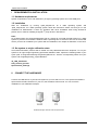
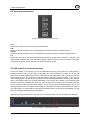
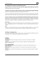
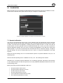
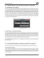
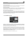
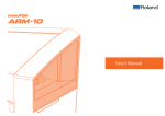
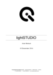
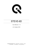
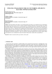
iQ-LED control software
user manual – sw.ver. 1.0.2
Image Engineering GmbH & Co. KG . Augustinusstraße 9d . 50226 Frechen . Germany
T +49 2234 995595 0 . F +49 2234 995595 10 . www.image-engineering.de
iQ-LED control software
CONTENT
I
REQUIREMENTS & INSTALLATION ................................................................................................ 3
1.1 Hardware requirements ........................................................................................................ 3
1.2 Installation ............................................................................................................................. 3
1.3 Set system to origin calibration state .................................................................................... 3
II
CONNECT THE HARDWARE........................................................................................................... 3
III STARTING THE SYSTEM ................................................................................................................ 4
IV SOFTWARE CONTROL / MAIN FUNCTIONS ................................................................................. 5
4.1 Measuring field ..................................................................................................................... 5
4.2 Spectrometer control ............................................................................................................ 6
4.3 Preset area ........................................................................................................................... 6
4.4 Reference area ..................................................................................................................... 6
4.5 System measurements ......................................................................................................... 8
4.6 LED control and channel intensity ........................................................................................ 8
4.7 Illumination and dim area / Adapting intensity ...................................................................... 9
4.8 Status / Information line ........................................................................................................ 9
4.9 Menu ..................................................................................................................................... 9
V
TEST SEQUENCE .......................................................................................................................... 10
VI
GENERAL SETTINGS ................................................................................................................... 10
VII CALIBRATION ............................................................................................................................... 11
7.1 Spectral calibration ............................................................................................................. 12
7.2 LUX calibration ................................................................................................................... 13
7.3 Neutral density filter ............................................................................................................ 13
7.4 Spectrometer calibration ..................................................................................................... 13
7.5 Dark measurement ............................................................................................................. 14
VIII MANAGE PRESETS / SELF DEFINED OR ADAPTED ILLUMINANTS ...................................... 15
8.1 Save/Manage Preset Window ............................................................................................ 15
8.2 Self defined or adapted illuminants .................................................................................... 15
IX EXTERNAL MEASUREMENT / GENERATE MEASURED ILLUMINANTS .................................... 15
X
SPECTROMETER SETTINGS ....................................................................................................... 16
XI
LOW INTENSITY USE .................................................................................................................. 17
XII
SYSTEM TEMPERATURE, AMBIENT TEMPERATUTE AND ENVIRONMENT CONDITIONS . 17
XIII SAFETY INFORMATION ................................................................................................................ 18
XIV SOFTWARE CHANGELOG………….…………………………………………………………………..19
Image Engineering
2
iQ-LED control software
I
REQUIREMENTS & INSTALLATION
1.1 Hardware requirements
System requirement is a PC with windows 7 (or higher) operating system and a free USB ports.
1.2 Installation
Start the installation by running ‘iqled_setup64.exe’ for a 64bit operating system and
‘iqled_setup32.exe’ for a 32bit operating system, follow the instructions. Make sure that you run the
installation as administrator. If there any problems with driver installation when using windows 8
rd
please use our manual ‘Installing unsigned 3 party drivers in Windows 8’.
Note:
On a 64bit system only the 64bit application will run, please do not install the 32bit version on a 64bit
system! If you have to reinstall the software after a operating time of more than 50 hours of the iQ-LED
device you have to recalibrate your system after the installation, see chapter 6 ‘calibration’ in this case.
1.3 Set system to origin calibration state
All iQ-LED illumination products will be tested and fully calibrated before the shipment. To set your
system to its origin Image Engineering performed calibration state, replace the following folder in your
sytem path ‘C:\ProgramFiles\Image Engineering\iQLed1.0.1’ with the corresponding folder from your
system CD ‘ImageEngineering_originCalibration’:
iQ_LED_Calibration
LED_Channel_Presets
Spectrometer_Settings
II
CONNECT THE HARDWARE
Connect the USB device of your iQ-LED system to your PC and turn it on. The system will install the
spectrometer and iQ-LED driver on your PC, this will take a few seconds. You can check the
installation in your hardware manager:
Hardware Manager: aktiv iQ–LED and spectrometer
Image Engineering
3
iQ-LED control software
III
STARTING THE SYSTEM
Start the iQ-LED control software by clicking the ‘iQ-LED.exe’ or the iQ-LED icon on your desktop. The
system will start a warm up every time you start the software, therefore all LED channels will be set to
there maximum intensity. This will approximate take less than two min depending on the ambient
temperature.
warm-up window
Also the system will perform a self test when starting the software. If the initial intensity or calibration is
not correct you will get a message. After finishing the warm up you will see the main window of the
software:
Image Engineering
4
iQ-LED control software
IV
SOFTWARE CONTROL / MAIN FUNCTIONS
4.1 Measure window
Here you can see your active spectral measurement and illuminant presets:
•
Orange curve:
Absolut spectral measurement of LED device (µWatt/cm²/nm)
•
Blue curve:
Reference curve, either a standard illuminant or any predefined spectrum that describe how
the optimal spectrum of your illuminant should look like
•
Green curve:
Absolut spectral measurement of an external measure device EX1 (µW/cm²/nm). See chapter
8 ‘External measurement’ for detailed information about the external measurement
•
If there is no active measurement you will see a grey image-engineering logo in the
measurement area
If you click on a LED color slider in the LED control area you will see a thin grey help line that shows
you the peak wavelength of the actual used LED channel.
If ‘Measure Peak Wavelength’ in the spectrometer settings window is activated you see the peak
wavelength value of the active measurement in nm, see chapter 9 ‘Spectrometer settings’ for detailed
information about a peak wavelength measurement.
The measure window will scale automatically when changing intensity, so you will have an overview of
the whole spectral measurement all the time.
The neutral density filter correction has no effect on this window, see chapter 6 ‘Calibration’ for
detailed information about the neutral density correction.
Measure window - standard illuminant D65 preset (blue curve) and LED generated (orange curve)
Image Engineering
5
iQ-LED control software
4.2 Spectrometer control
After starting the software the system automatically starts a absolute spectral measurement, you will
see the result of the measurement in the measure window.
Start / stop button:
With the start/stop button you can start or stop the absolute measurement any time. After some
actions (a calibration or external measurement, for example) you have to restart the measurement by
pressing this button. If no measurement is running you will see the Image Engineering logo in the
measurement area.
Save button:
Save the actual spectral LED measurement as a txt file, this file can be loaded as a reference in the
reference area, see chapter 4.4 ‘reference area’ for detailed information.
4.3 Preset area
Standard illuminant menu box:
Here you can choose from different predefined illuminants. Just click on an illuminant in the pop up
menu or scroll through the different illuminants.
All illuminants are defined to give a high intensity with the best spectral match for this illuminant in your
system. If the spectral measurement is running you will see the spectrum of the chosen standard
illuminant how it should be by a blue line (reference spectrum) and the measured LED spectrum as an
orange line (measured LED spectrum). If you like to decrease or increase these predefined illuminants
see chapter 4.7 ‘Adapting intensity’. How accurate your actual illuminant is generated you can see in
the ‘system measurements’ area.
custom menu box:
This pop up menu works the same such as the standard illuminant menu. Here you will find illuminants
that are generated and saved by yourself, for this option see ‘manage presets’. You will also see some
predefined colors in this area and you can set all channels to its maximum by choosing ‘allMax’. All
presets are defined by the slider positions and, if existing, by a given reference spectrum.
Off button:
If you click this button all channels will be set to zero and the reference curve will be removed.
4.4 Reference area
Generate button:
Here you can start the auto generate algorithm. The measurement has to be active and there must be
a blue reference curve. This could be a reference from an external measurement (see chapter 8
‘External measurement’), a LED light setting that has been saved as a reference (see ‘save button’ in
chapter 4.2 ‘Spectrometer control’) or any other kind of imported spectral curve. If you start the auto
generate the system will automatically generate a spectrum according to the given blue reference.
This will take around 1 or 2 seconds. You will see the result directly after the generation process, the
measured LED spectrum will look as close as possible to the given blue reference. The fit value in the
measurement area shows how accurate the measured LED spectral curve will accord to the given
blue reference in percent.
Image Engineering
6
iQ-LED control software
Please note:
When generating a spectrum you have to ensure that the reference is not higher than the maximum of
the LED channels. If the curve fit value is unexpected low and the measured curve is lower than the
reference some LED channels reached their maximum. You can see the intensity of any channel in
the channel intensity window, or check the corresponding slider position. Also see ‘degradation
warning’ in chapter six.
So when generate a given spectrum, please make sure that no LED channel reaches his maximum.
Import button:
If the measurement is running you can load a given spectrum from a txt file as a reference by pressing
this button. For example a curve from an external measurement can be imported as a new reference
from here. You will see the imported reference spectrum as a blue curve in your measuring field.
Save button:
With this button you can save the active reference curve via a file dialog. This is needed if you have
scaled a reference and want to use it again in later time, for example.
If you like to import a spectral curve from an existing file (excel for example) you have to create a txt
file for an import. Every row in this file have to correlate to one measure value: wavelength and
intensity separated by a tab.
Scale button:
If you have an active reference curve in your neasuring field you can scale this reference by clicking
this button. You can type in the scale factor, press the ok button and the reference curve will increase
or decrease by the given factor. This is important if your given reference will be to high to be
generated by the LED channels.
Scale reference window
Clear button:
Pressing this button will delete a active reference curve.
Image Engineering
7
iQ-LED control software
4.5 System measurements
System measurements: standard illuminant D65
CCT:
Shows the actual measured correlate color temperature.
CRI:
Shows the actual measured color rendering index (not active in external measure mode).
Degree:
Shows the actual temperature of your iQ-LED devices [ºC] (not active in external measure mode).
Fit:
Shows the curve fit of the actual measured LED spectrum to the active reference in percent. This
value will be actualized only when generating a given reference, dim an actual curve with a reference
or pressing the ‘get fit’ button (not active in external measure mode).
4.6 LED control and channel intensity
Via the 22 sliders or spin boxes you can increase/decrease every LED channel in 1000 steps by
pushing the slider, type in a new value or scrolling your mouse wheel over a slider. W1 is the cold
white channel, W2 the warm white channel. The color channel peaks start in the UV near area (around
420nm) and go up to the IR near area (around 800nm) with rising channel number. If you have an
active measurement you will see a grey help line in the measuring field when clicking a color channel
slider. This helpline show you the peak wavelength of the actual used channel. In the intensity area
you see the intensity arrangement of all your color channels, the intensity of the two white channels
can be checked by the according slider position. If you use the control software together with an iQLED light HEAD, there will appear another slider to control the intensity of the fluorescence tubes of
your light HEAD. The slider will be automatically activated when connecting the light HEAD, you will
see it on the right border beside the LED sliders.
With the small arrow button on the left side of the channel windows you can show/hide the slider bar.
Channel intensity bar – standard illuminant D65
Image Engineering
8
iQ-LED control software
4.7 Illumination and dim area / Adapting intensity
In the intensity area you see the intensity of your actual light. The lux value correlates to the measured
illuminance [lux] in the chart level, the watt value is the irradiation power [mW]. Both values are
measured by the internal micro spectrometer.
To increase or decrease your intensity just type in a new Lux or Watt value in the field beneath and
press enter or the ‘set’ button. If there is a reference spectrum, the software will increase or decrease
the reference and generates a new spectrum according to the reference.
If there is a wide difference between the actual and the new intensity, the software might not be able
to achieve the correct value directly. In this case just press the ‘set’ button again to get a better result.
If there is no reference curve in your measuring field the software will generate a new reference curve
from your current measurement, this new reference will be used from the software to increase or
decrease your active curve. So after the dim process you will see a new blue reference curve with the
same shape of your measurement. You can use it as a new reference, if you want to save this
intensity as a new preset, or delete it by pushing the clear button in the reference area.
Please note:
Due to quantization errors and noise effects, dim up from a very low intensity to a higher value could
cause nonsatisfying results. So it is recommended to choose a higher intensity and dim down, if
possible.
Hint:
If there is an illuminant that will be used with different intensities oftentimes, it may be more
comfortable to save these as self defined presets, see chapter 7 ‘Manage Preset’ for this option.
4.8 Status / Information line
Here you will get a feedback from the software in form of a short message what happened after your
last operation. You also get warnings if the system will not work correct.
4.9 Menu
MAIN MENU
Test Sequence: Open the test sequence window, see chapter 5 ‘Test sequence’ for detailed
information.
Calibration: Open the calibration window, see chapter 6 ‘Calibration’ for detailed information.
Quit: Close the application.
SPECTROMETER MENU
External Measurement: Start external measurement, see chapter 8 ‘External measurement’ for
detailed information.
Measure dark: Perform a dark measurement, see chapter 6.5 ‘Dark measurement’ for detailed
information.
Settings: Open the spectrometer settings window, see chapter 9 ‘Spectrometer settings’ for detailed
information.
Image Engineering
9
iQ-LED control software
LED PRESET MENU
Save/Manage presets: Show the preset manage window, see chapter 7 ‘Manage presets’ for detailed
information.
Save setting to file / Load setting from file: Open a file dialog where you can save the actual light
setting (defined by the actual slider setting) as a txt file. So you can import/export different light
settings. These txt files can be loaded in the sequence function, see chapter 5 ‘Test sequence’ for
detailed information.
V
TEST SEQUENCE
Test sequence window
With the test sequence module you can create and start a test procedure with different settings. You
can add predefined illuminants from the left side and put them to the sequence list on the right side.
The remove button will remove the chosen illuminant from the sequence list, the clear button will
delete the whole list. With the tabs ‘standard illuminant’ and ‘custom’ you can change between the
defined illuminants of the according drop boxes from the preset area. The ‘add ext.’ button opens a file
dialog where you can choose light settings from txt files.
The chosen illuminants will be shown in the list on the right. You can delete the whole list by clicking
the clear button, if you choose just one illuminant, only this one will be deleted.
In the ‘Step time’ box you can adjust how long any illuminant will be active, minimum time should not
be less then 40ms. The number of ‘Sequence cycles’ define how often the light set list will pass
through. The ‘start sequence’ button will start the sequence, you will see the actual illuminant
highlighted in the list. The small bar in the lower part of the window will show the progress of the whole
test procedure.
Image Engineering
10
iQ-LED control software
VI GENERAL SETTINGS
General settings window
Degradation warning:
When generating or changing intensity of a spectrum the software automatically checks if the new
spectral curve could be generated after an estimated longtime degradation of the LEDs. If this option
is enabled you will get a warning after a generating procedure or changing intensity, if any of your
channels are to high (in default setting this option is enabled).
Presentation mode:
If this option is enabled the background in the measuring field turns to from grey into white and the
curve is displayed with a thicker line to get a better display contrast (in default this option is disabled).
Image Engineering
11
iQ-LED control software
VII
CALIBRATION
Make sure that you run the software as administrator before performing any kind of calibration or dark
measurement. Otherwise the system will not save your changes or measurements.
Window for spectral calibration, lux calibration and neutral density correction
7.1 Spectral calibration
The LEDs in the iQ-LED light sources are of many different types and wavelengths. Some LEDs will
change their intensity level and peak wavelength a bit in the first 600 working hours because of a burn
in effect. The LEDs also will degrade in intensity while their whole life time. To make sure that all
measurements, the auto generate and the standard illuminants are correct, you have to perform a
spectral calibration regulary. Also you have to consider the degradation of the LED when saving self
defined presets. If you save a preset with LED channels that uses its maximum intensity, it might be
that this intensity can not be reached after the burn in time or a long time degradation of the LED
anymore.
While the first 600 working hours it is recommended to perform a spectral calibration every 30 - 50
operating hours.
After the first 600 operating hours a calibration of every 130 - 150 working hours suffices.
Indications for a necessary spectral calibration is a not satisfying generate, aberration of the intensity
or oher measured values or that the spectral curve of the predefined standard illuminants fit not to the
corresponding preset.
Before performing a spectral calibration make sure:
•
•
•
•
•
•
the spectrometer works correct
the spectrometer settings are correct
all LED channels work correct
the dark measurement is correct
your measurement environment is correct
your ambient temperature is correct
Image Engineering
12
iQ-LED control software
•
•
there is no interfering light
your system is warmed up and is turned on since minimum five minutes
To start the spectral calibration just click the ‘Start spectral calibration’ button. The calibration will take
around 3 minutes. You will get a message when the calibration is finished. After the calibration is
complete, check your system by choosing the different predefined illuminants and verifying the
measurement values.
After a spectral calibration you also have to check your self defined illuminants. If the measurement
values or the spectrum are not correct you have to perform an auto generate of your self defined
illuminants and save the new generated spectrum via the ‘Manage preset function’. You can save the
regenerated illuminants in the manage presets window using the same name as before by choosing it
from the combo box.
7.2 Lux calibration
This calibration has to be used only if something in your hardware setup has been changed
(replacement of a iQ-LED element, the spectrometer, the spectrometer sphere fixture or the
integrating sphere). It is also recommended to check your illuminance values after a spectrometer
calibration.
This calibration defines the position and measured value of the displayed illuminance value of your
device. You need a lux meter to perform this calibration. Follow instructions after clicking ‘Start Lux
calibration’ for a new calibration. Place the lux meter for the reference value in the center of the
measure area. After a lux calibration it is recommended to perform a spectral calibration.
7.3 Neutral density filter
If you use a neutral density filter you can type in a transmission correction value for your filter in the
corresponding box (for example: the correction value for a 50% / 0.3D filter is 0.5). After pressing the
set button, the measured intensity values will correspond to the values behind your filter. The default
value when using the system without a filter is 1.
7.4 Spectrometer calibration
Your spectrometer comes fully calibrated. It is recommended to recalibrate the spectrometer once a
year, regardless of the operating hours. If a spectrometer calibration is required please contact Image
Engineering, we will provide you with a removal instruction. After the removal the spectrometer has to
be sent to our office with a notation for calibration.
After you have reinstalled the new calibrated spectrometer you have to perform a spectral calibration.
Please note a measured LUX value of a predefined standard illuminant before removing the
spectrometer, to check your intensity values after the spectrometer is calibrated and reinstalled to your
system. If the Intensity values are not correct after the spectral calibration, you have to perform a LUX
calibration.
Image Engineering
13
iQ-LED control software
7.5 Dark measurement
It is possible to save the actual spectral measurement as dark, via the ‘Measure dark’ option in the
spectrometer menu. This measurement stands as a zero offset for the system and its measurements.
If you perform a dark measurement make sure that all channels are set to zero. The iQ-LED device
also should be placed like it will be used in your test environment, without any interfering light. The
default dark measurement of your system is measured without any incoming light.
Image Engineering
14
iQ-LED control software
VIII
MANAGE PRESETS / SELF DEFINED OR ADAPTED ILLUMINANTS
8.1 Save/Manage Preset Window
Here you can manage your self defined presets, you will find this option in the LED preset menu. A
new preset could be a standard illuminant with adapted intensity, illuminants are generated according
to an external measurement or self defined spectra via a slider setting. If you press the save button the
actual light setting (defined by the slider setting) will be saved with the given name from the ‘new
name’ box. If there is also an active reference curve in the measuring field it will be saved as well. If
you chose ‘empty’ in the combo box a new preset will be generated, you will find it in the ‘self defined
preset’ list in the main window. You can also overwrite existing presets by choosing an existing
illuminant in this combo box. This is necessary if you have performed a calibration and regenerate
your self defined illuminants. You also can delete existing presets by choosing the set you don’t need
any more and click the delete button.
Manage presets window
8.2 Self defined or adapted illuminants
If you have a self defined illuminant without a matching reference, you will not have any information of
your origin spectrum in later time. In this case it is recommended to create a new reference of your
generated spectrum via the save button in the spectrometer area and import it as a new reference.
Therefor use the import button in the reference area, if there still is an active, not matching reference,
you have to press the clear button to delete it. After that save your self defined spectrum together with
the new reference, so you are able to regenerate it after a future calibration.
Note: Without a matching reference it is not possible to regenerate your self defined spectrum
after a calibration!
IX
EXTERNAL MEASUREMENT / GENERATE MEASURED ILLUMINANTS
For an external measurement you need the Image Engineering external measurement device EX1.
Start external measurement:
For an external measurement you have to stop your actual measurement. After that press ‘external
measurement’ in the spectrometer menu. You will see a message box and will be asked to disconnect
your iQ-LED device and connect your external measure device EX1. Now you can start the external
measurement by pressing OK in this box. You will see your actual measurement as a green curve in
the measuring field.
Image Engineering
15
iQ-LED control software
If you have to measure light sources with very low or high intensity you can adapt the spectrometer
settings, please see next chapter 9 ‘Spectrometer settings’ for this option.
Save external measurements:
If you want to save the external measurement click 'save' in the spectrometer area. You can import this
measurement as a reference, when using your iQ-LED device in normal mode.
Stop external measurement:
Just press the start/stop button in the spectrometer area. You will see another message box. Now you
have to disconnect your external measure device EX1 and plug in your iQ-LED device again. After
pressing the OK button in the message box you can use your iQ-LED device as usual.
Import and generate external measurements:
You can import your measured spectrum in the reference area by pressing the import button, make
sure that there is no other active reference before. After the import just press the generate button to
generate the measured light source. Make sure that your imported external measurement is scaled
well, so that there is enough intensity in all LED channels to generate it. For detailed information about
generating a reference, see chapter 4.4 ‘reference area’.
X
SPECTROMETER SETTINGS
Spectrometer settings window
All settings of the spectrometer are optimized for your system, so only change them if needed while
performing an external measurement (except the ‘measure peak wavelength’ check box). With the
save button you change the spectrometer settings to the given values. After finishing the external
measurement make sure that you recovered the origin values.
When opening the spectrometer settings while an external measurement is running, you will see a
message box how to go back to a normal measurement, this is the same message when stopping the
external measurement. You can ignore the message and press cancel, if you want to go on with the
external measurement after changing the spectrometer settings. The spectrometer settings window
will appear. After saving the new settings you can restart the external measurement by choosing
‘external measurement’ in the spectrometer menu again.
Default spectrometer values depend on the iQ-LED device you use.
Image Engineering
16
iQ-LED control software
Integration Time [sec]:
The integration time in seconds is analogous to the shutter speed of a camera. The higher the
integration time, the longer the detector monitors the incoming photons. If your measured intensity is
to low, increase this value. If the intensity is to high, decrease this value. Maximum values are 10
µsec. – 10 sec. (enter values: 0.00001 – 10.0).
Scans to Average:
Specifies the number of discrete spectral acquisitions that the device driver accumulates before the
software receives a spectrum. The more scans to average you use, the slower your system will
measure.
Boxcar Width:
The greater this value, the smoother the data and the higher the signal-to-noise ratio. If the value
entered is to high, a loss in spectral resolution will result.
Measure Peak Wavelength:
If the measure peak wavelength check box is activated you will see the measured peak value of the
actual spectrum in your measuring field. You can use this option while performing an external
measurement and in the LED mode as well.
XI
LOW INTENSITY USE
When using your system with very low intensity, the measured values will start to fluctuate. The lower
the intensity, the higher is the fluctuation. That does not mean that the generated light is instable. The
fluctuation of the values is caused by noise of the spectral measurement of the internal micro
spectrometer. The influence of the noise gets higher, the lower the light intensity is. When using
illuminants with intensity lower than 25lux it is not possible to get any approximately correct value any
more. If very low light intensities are required, please use a neutral density filter and activate the
neutral density correction in the calibration window. This way the light source will run at higher intensity
while having low intensity in the chart plane.
XII SYSTEM TEMPERATURE, AMBIENT TEMPERATUTE AND ENVIRONMENT
CONDITIONS
Please place your system in a dry and constant tempered environment without any interfering light.
The optimal system temperature range, displayed in the measurement area, is between 32 and 38
degrees Celsius.
The optimal ambient temperature range is 22 to 24 degrees Celsius. The maximum ambient
temperature range is 19 to 29 degree Celsius. If the system temperature gets higher than 38 degrees
Celsius please check your ambient temperature.
The system has an internal temperature management, if there is any error regarding the internal
temperature you will get a warning message and the system automatically turns off to avoid any
damage.
Image Engineering
17
iQ-LED control software
XIII
SAFETY INFORMATION
•
Some LEDs are emitting invisible light in the IR and UV near area.
•
DO NOT look directly into the emitted light or look through the optical LED system.
•
DO NOT look directly in the open sphere or light source when using high intensities or
sequences with low response time.
•
DO NOT open the device without any instructions from the Image Engineering support and
when connected to the power supply.
XIV
Software changelog
Modifications from ver.s 1.0.1 to 1.0.2:
Added slider for fluorescence tube intensity control, usage only together with iQ-LED light HEAD.
Image Engineering
18