1
The Mentor
Matthew Addison
Prism 2 User Manual
Prism 2 Design Team
Bob Hollis
Chauncey Chapman
Art Ferguson
Robert Landreth
Matthew Addison
Peter Readey
Prism 2 Manual written by
Matthew Addison
Bruce Partridge
Edited by
Jeffrey Bozanic
Chauncey Chapman
John Conway
Gerard Newman
Contributors
Jeffrey Bozanic
Gerard Newman
Dr. Richard Pyle
Sharon Readey
Kevin Watts
Hollis Prism 2 eCCR User Manual
Version 1.0
Document Control number: 12-4072
Publish date: 03/15/2012
©2012 Hollis
You may not reproduce this manual in whole or in part
without the express written permission of Hollis.
Version 1.0
i
Prism 2 User Manual
General Safety Statements
and WARNINGS:
No person should breathe from, or attempt to use in any way, a Hollis Prism 2 rebreather,
or any component part thereof, without first completing an appropriate Hollis Certified
user-training course.
Further, no Prism 2 diver should use a Hollis Prism 2 without direct Hollis instructor supervision
unless they have mastered the proper set-up and operation of the Hollis Prism 2. This includes
new Prism 2 divers as well as Prism 2 certified divers who have been away from diving for 6
months and would benefit from an instructor-led refresher course to regain skills mastery of the
Hollis Prism 2. Failure to do so can lead to serious injury or death.
The Prism 2 rebreather can, as with any closed breathing loop, circulate breathing gas that
may not contain a sufficient quantity of oxygen to support human life. The breathing gas within
the Hollis Prism 2 loop must be closely monitored and manually maintained with a safe oxygen
content by you (a properly trained and alert user) at all times.
The computer-controlled addition of oxygen to the breathing loop is intended only as a fail-safe
back-up system to you, the primary controller. If you (either knowingly or by inattention) allow
the computer to control oxygen addition to the breathing loop at any time, you are diving outside
the principals of your training. By abdicating user responsibility and system control to a machine,
whether intentionally or not, you assume all risk to life and limb that may result.
WARNING
High Pressure Oxygen
The Prism 2 uses cylinders, gas feed lines, pressure gauges and other devices which will contain
pure oxygen at high pressure when in operation. Oxygen by itself is non-flammable, however it
supports combustion. It is highly oxidizing and will react vigorously with combustible materials.
Oxygen at elevated pressure will enhance a fire or explosion and generate a large amount of
energy in a short time.
The user must maintain all parts of the Prism 2 that can come into contact with high-pressure
oxygen as oxygen-clean components. This includes scheduled servicing by a Hollis service
professional, and using approved oxygen-compatible lubricants on any part of the pneumatic
systems that will come into contact with high-pressure oxygen.
If any part of the oxygen-clean system comes into contact with contaminants or is accidentally
flooded with any substance (including fresh water), you MUST have the entire high-pressure
oxygen system serviced by an authorized Prism 2 service professional prior to use. Failure to do
so can cause fire or explosion and lead to serious injury or death.
ii
Version 1.0
Prism 2 User Manual
WARNING
Design and Testing
The Hollis Prism 2 has been designed and tested, both in materials and function to operate
safely and consistently under a wide range of diving environments. You must not alter, add,
remove or re-shape any functional item of the Hollis Prism 2 or substitute any part of the Hollis
Prism 2 with third-party items that have not been tested and approved by Hollis for use with the
Prism 2.
This includes, but is not limited to, hoses, breathing assemblies, electronics, pneumatics
assemblies and their constituent parts, sealing rings, valves and their constituent parts and
sealing surfaces, latches, buoyancy devices, inflation and deflation mechanisms and on-board
alternate breathing devices.
Altering, adding, removing, re-shaping or substituting any part of the Hollis Prism 2 with nonapproved parts can adversely alter the breathing, gas delivery or CO2 absorption characteristics
of the Hollis Prism 2 and may create a very unpredictable and dangerous breathing device,
possibly leading to serious injury or death.
Non-approved alterations to functional parts will automatically void all factory warranties, and
no repairs or service work will be performed by any Hollis service professional until the altered
Prism 2 unit is brought back into factory specifications by a Hollis service professional at the
owner’s expense.
WARNING
Computer/controller-specific warnings
This computer is capable of calculating deco stop requirements. These calculations are predictions
of physiological decompression requirements. Dives requiring staged decompression are
substantially more risky than dives that stay well within no-stop limits.
Diving with rebreathers and/or diving mixed gases and/or performing staged
decompression dives and/or diving in overhead environments greatly increases the risks
associated with scuba diving.
WARNING
Computer Software
Never risk your life on only one source of information. Use a second computer or tables. If
you choose to make riskier dives, obtain the proper training and work up to them slowly to gain
experience.
Always have a plan on how to handle failures. Automatic systems are no substitute for knowledge
and training. No technology will keep you alive. Knowledge, skill, and practiced procedures are
your best defense.
Version 1.0
iii
Prism 2 User Manual
WARNING
User-packed radial scrubber
As of this writing, the Hollis Prism 2 design does not include any technology or other device
which can detect or warn of potentially dangerous levels of carbon dioxide (CO2) within the
breathing loop.
The Hollis Prism 2 utilizes a user-packed, radial design CO2 scrubber. Only Hollis tested and
approved CO2 absorbents should be used, and factory-stated maximum scrubber durations
must never be exceeded. Exceeding factory stated scrubber durations for a particular material
will eventually lead to serious injury or death.
It is entirely possible that, for any number of reasons including but not limited to: channeling,
ambient temperature, exhausted, damaged, inappropriately stored, or (for whatever reason),
inert scrubber material, the chemical and thermodynamic reaction required to sequester gaseous
CO2 will not occur as expected, and a toxic, and possibly fatal level of gaseous CO2 within the
breathing loop can result.
You must carefully follow all instructor and manufacturer recommendations for use and handling
of CO2 absorbent, never use a CO2 absorbent if you cannot verify that it is able to sustain CO2
absorption and carefully pack the radial scrubber and complete a system pre-breathe prior to
each immersion, as you were taught in your training course.
Further, you must carefully monitor yourself for any symptoms of possible CO2 poisoning
whenever you are breathing from the Hollis Prism 2, and bail-out to open circuit should any
physical or mental symptom lead you to suspect elevated CO2 levels in your breathing loop.
Failure to bailout at the first sign of trouble can lead to serious injury or death.
WARNING
Weighting of the Hollis Prism 2
Unlike open circuit scuba gear, it is possible for the Hollis Prism 2 breathing loop to flood, causing
the rebreather to quickly become 17 pounds negatively buoyant (not including any user-added
weight or offsetting buoyancy inflation). It is the responsibility of the diver to insure that the Hollis
Prism 2 is never weighted in such a way that it is not possible for the installed buoyancy device
to overcome the flooded weight of the unit plus any diver-added non-detachable weights, and
still provide enough positive buoyancy at the surface to keep the divers head well above water.
Consult your instructor, dealer, or call the Hollis factory directly with any questions or concerns.
Failure to maintain positive buoyancy at the surface with the Hollis Prism 2 in a fully flooded state
can lead to serious injury or death.
iv
Version 1.0
Prism 2 User Manual
Caution
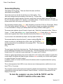
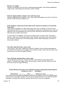
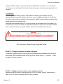
Batteries tested in the Prism 2
It is strongly recommended that only name-brand batteries (such as “Duracell” or “Eveready”)
are used to power the Prism 2. Off-brand / Discount batteries have been found to vary greatly
in quality of materials from batch to batch (and even piece to piece!) and therefore may not
perform as expected, or be capable of consistently delivering the power required to drive the
components, despite battery voltage levels reported by a battery voltage meter.
WHILE OFF-BRAND / DISCOUNT BATTERIES ARE PERFECTLY ACCEPTABLE FOR USE IN
TOYS AND FLASHLIGHTS, THEY HAVE NO PLACE IN LIFE SUPPORT GEAR AND MUST
NEVER BE USED TO POWER ANY COMPONENT OF YOUR PRISM 2.
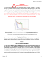
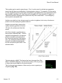
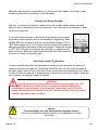
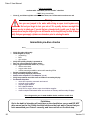
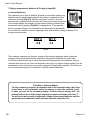
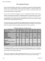
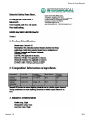
Diagram showing rapid discharge of non-branded batteries, which in life support gear can result in
unnecessary hazards.
Image courtesy of Rhett Allain, Wired
The full article, “Are-expensive-batteries-worth-the-extra-cost” is available at www.wired.com
Rechargeable Batteries
Because of the potential rapid drop-off of charge from rechargeable batteries, rechargeable
batteries are not recommended for use with your PRISM 2 rebreather and must not be used.
Note
Use of the Prism 2 User Manual
This user manual does not, nor is it intended to contain any information needed to safely dive
with any type of SCUBA apparatus. It is designed as a guide for the proper setup, operation,
maintenance, and field service of the Hollis Prism 2 CCR only. It does NOT take the place
of a recognized training agency instructor-led diver-training course or its associated training
manual(s) and materials. This user manual is intended to be used only as a type specific addition
to such training and materials, and as a user reference. This manual cannot be used as a
substitute guide for any other type of Self Contained Underwater Breathing Apparatus (SCUBA).
Version 1.0
v
Prism 2 User Manual
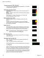
Table of Contents
Prefacei
Warningsii
Welcomexiii
Forewordxiv
Part 1 - System Overview
Philosophy2
Manual Control or Computer Control2
Getting to know your Prism 2 – Schematics & Design
3
The Gas Path3
Oxygen and the exhalation side of the loop
4
The OPV (Over-Pressure Valve)
4
Exhaust Plenum4
The Scrubber
6
The Inhalation Counterlung
6
The DSV (Diver Shut-Down Valve)
8
The BOV (Bail-Out Valve)
8
Battery Compartment Cover10
Battery Compartment10
O2 Sensors, Sensor Holder, Connector & Pins
10
Solenoid10
Solenoid Electrical Connections11
Solenoid O-Rings11
Bucket Sealing O-Rings
11
Article: “The Solenoid and the PID Controller”
12
Bucket Latches
14
Basket Spring on Bucket
14
Absorbent Basket Assembly
14
Backplate
15
O2 and Diluent First Stages
15
Fitting your Prism 2
16
Article: “Stability” by Gerard Newman
18
Article: “Taking care of your Oxygen Sensors”
21
Part 2 – Displays and Electronics Operation
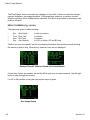
Displays and Controllers27
LED Primary Display27
Light State Table
28
Low Battery Warning
28
Secondary Display29
Buttons31
Menu32
Menu Structure33
vi
Version 1.0
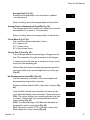
Prism 2 User Manual
Basic Setup34
Display Elements Descriptions35
Fraction Inspired O2
36
Ascent Bar Graph
36
Battery Symbol
36
Depth
36
Dive Time
36
Stop Depth and Time
36
Average Depth37
Average Depth in Atmospheres37
Circuit Mode37
Current Gas37
No Decompression Limits37
Ceil37
GF9937
@+537
Time to Surface
38
Maximum Depth
38
CNS Toxicity Percentage
38
Setpoint
38
Average PPO2
38
Diluent PPO2
38
Gas PPO2
38
Gradient Factor
38
Decompression and Gradient Factors
39
Article: “Gradient Factors Explained” by Kevin Watts
40
VPM-B/GFS Explained43
Pressure44
Temperature44
External Voltage
44
Internal Voltage
44
Millivolts44
Date and Time44
Serial Number44
Version
44
Surface Interval44
Example Dive45
Menu Reference48
Calibration Problems49
External Battery (Solenoid Battery) Alerts
50
Switch Setpoint51
Select Gas52
Radio Station Gasses52
Switch to OC/CC53
Dive Setup+53
Low Setpoint53
High Setpoint54
Version 1.0
vii
Prism 2 User Manual
Define Gas
55
Dive Planner+57
NDL Display
60
External PPO2 Monitoring62
Setpoint -> .1963
Dive Log Menu64
Display Log
64
Upload Log
64
Edit Log Number
64
Clear Log
64
Firmware Upload and Dive Log Download Instructions
65
System Setup68
Dive Setup
68
OC Gasses
68
CC Gasses
68
O2 Setup
68
Cal PPO2
69
Article: “When to use the “Cal. PPO2 function. Diving your
Prism 2 with O2 fills of less than 99.8% purity
70
Solenoid Speed72
Set SC Identity
72
Auto SP Switch72
Display Setup73
Units
73
Brightness Range73
Altitude74
Flip Screen74
System Setup75
Date75
Time75
Load Upgrade
75
Reset to Defaults75
Advanced Configuration Menus
76
Salinity
76
Title Color77
OC Show PPO277
End Dive Delay77
Advanced Configurations Pg 2
77
OC Min PPO2
78
OC Max PPO2
78
OC Deco PPO2
78
CC Min PPO2
78
78
CC Max PPO2
Error Displays79
Battery Change82
Storage83
Warning83
viii
Version 1.0
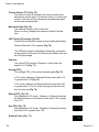
Prism 2 User Manual
Specifications
83
Part 3 – Setting Up Your Prism 2 eCCR
Packing the Prism 2 CO2 Scrubber84
Cleaning your empty scrubber
89
Disposing of used CO2 absorbent
89
Setting up your Prism 2 using Checklists
90
Why a multi-stage checklist format
90
Pre-Assembly/Packing Checklist
92
Assembly Checklist
94
Operational and Intra-Dive Checklist
95
An O-Ring Cleaning Primer
98
Numbered Checklist for Training
99
Checklist Items How-to103
Pre-Assembly/Packing Checks103
1) Check H-Plate, Harness, Bladder
103
2) Inspect Counterlungs
105
3) Counterlung to DSV/BOV hoses
107
4) Inspect DSV/BOV
109
5) Inspect Pneumatics
109
6) Inspect Wiring
110
7) Battery Compartment111
8) Solenoid Operation
113
9) Inspect Head Assembly
113
10) Oxygen Sensors
116
11) Bucket Assembly
117
12) Basket Assembly
119
Assembly Checks121
13) Fill Scrubber121
14) Install head assembly onto H-Plate
121
15) Install bladder, yoke and backplate onto H-Plate
121
16) Run pneumatics lines, install solenoid gas hose
121
17) Attach Counterlungs to yoke
121
18) Install Counterlung breathing hoses to head
122
19) Attach Gas Supply Lines to Diluent and Oxygen Addition
Valves on Counerlungs, Bouyancy Device
122
20) Assemble DSV/BOV and Hoses, Check and Install
122
21)Clean Head to Bucket Sealing Rings
125
22) Clean Red CO2 Seal & Secure
126
23) Check filled CO2 scrubber basket
126
24) Install Bucket Moisture Pad
127
127
25)Place CO2 absorbent basket in bucket
Prism 2 Operational and Intra-Dive Checks
129
26) Fill O2 and Diluent Cylinders
129
27) Install filled and content verified gas cylinders
130
Version 1.0
ix
Prism 2 User Manual
28) Record O2 cell mV readings in air
130
29) Positive Pressure Test130
30) Diluent System Leak Test
131
31) Negative Pressure Test/ADV Test
131
32) Oxygen System Leak Test
133
33) Solenoid Test / Flush loop with O2133
34) Calibrate Secondary Display Electronics
134
35) LED Primary Display on and battery check
135
36) Calibrate LED Primary Display
135
37) Solenoid Batteries check
135
38) Secondary Display Battery Check
135
39) Adjust User Selected Low/High Setpoints
136
40) Record Oxygen Pressure after Loop Flush
136
41) Confirm Alternate Air Source Operation
136
42) Check Buoyancy Compensation Inflation/Deflation
137
43) Record Diluent Pressure137
--- Close O2 & Dil Cylinders, secure unit
137
44) Install weights
138
45) Verify LED Primary Display is Powered On
138
46) Don Unit, Secure Fasteners, Tighten Belts
139
47) Verify O2 & Diluent Valves are On
139
48) Secure Secondary Display on Wrist
139
49) Verify Secondary Display is On
139
50) Verify Loop Contents are within User Set limits
139
51) Pre-Breathe unit140
Post Dive Operations141
Post Dive Checklist142
Post Dive Checklist Step-by-Step
143
Verify and Record Batteries
143
Secure Primary Display143
Secure Secondary Display143
Drain Counterlungs of Fluid143
Remove Counterlung Weights144
Remove Weight Pockets, Weights
144
Soak complete, Sealed Unit if Fresh Water
144
Turn off O2 Valves, Drain lines
144
Turn off Diluent Valves, Drain lines
144
Detach Bucket from Head, Remove CO2 Basket, Record
144
Disinfect Bucket
145
Inspect O2 Sensors, Record Readings in air
145
Remove Counterlungs, Disinfect145
Drain and hang BCD/backplate/head assembly 146
Fill out Maintenance/Repair log
146
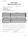
Prism 2 eCCR Maintenance/Repair Log Sheet
147
x
Version 1.0
Prism 2 User Manual
Part 4 – In-Water Skills
The Pre-Dive Equipment Check 149
Buoyancy Device149
Weights149
Releases149
Gasses149
Electronics149
Pre-Breathing your Scrubber150
In Water Skills and Drills
150
Skill 1:The In-water bubble check
151
Skill 2:Controlled decent
152
Skill 3:DSV/BOV shut-down drill
152
Skill 4:Mask clearing
154
Skill 5:Remove, clear & replace DSV/BOV
154
Skill 6:Emergency bailout – onboard breathing gas
154
Skill 7:Manual addition of diluent
155
Skill 8:Manual addition of oxygen
156
Skill 9:Minimum loop volume and the OPV
156
Article: “Minimum, maximum and optimal loop volumes and work
of breathing” by Dr. Richard Pyle
157
Skill 10: Manually maintain setpoint while stationary
158
Skill 11: Manually maintain setpoint on descent
158
Skill 12: Neutral buoyancy practice
159
Skill 13: Manually maintain setpoint while swimming
159
Skill 14: Manually maintain setpoint on ascent
160
Skill 15: Clear partially flooded loop
161
Skill 16: Diving with off-board open circuit system
163
Skill 17: Off-board bailot assist of another diver
164
Skill 18: Valve shutoff drills
164
Skill 19: Leak detection – disconnecting QD’s
165
Skill 20: Changing computer set-points underwater
166
Skill 21: Bailing out the computer to OC underwater
167
Skill 22: Deploying a surface marker buoy (SMB)
167
Optional: Using a drysuit with a rebreather
167
Skills and Drills Completion List
168
Article: The language of Oxygen
169
Part 5 – Maintenance & Troubleshooting
171
Non-User Serviceable Parts
172
Preventative Maintenance Schedule173
Battery Compartment Housing174
Replacing the Battery Cap Pressure Relief Valve
174
Battery Cap Locking Latches
174
Stainless Steel Roll Bar 174
Electronics Stack
175
Solenoid Chamber175
Exhaust Plenum175
Red CO2 Seal175
Version 1.0
xi
Prism 2 User Manual
O2 Sensor Holders
176
O2 Sensor Harness
176
176
O2 Sensors
Inhalation Counterlung hoses
176
Inhalation Counterlung and drain
177
Automatic Diluent Addition Valve
177
DSV/BOV Inhalation hose & fitting
177
DSV/BOV Exhalation hose & fitting
178
DSV
178
Exhalation Counterlung and drain179
Manual Oxygen Addition Valve
180
Scrubber Bucket & Basket Spring
181
Scrubber Basket
181
Buoyancy Device
182
H-Plate
182
Troubleshooting184
Mechanical drawings & part numbers
186
Part 6 – Addendum
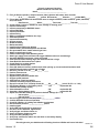
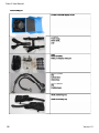
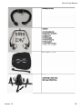
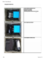
Prism 2 packing list
Prism 2 packing order
194
196
198
Part 7 – Material Safety Data Sheets200
DeOxIt Gold201
Intersorb203 Steramine208
xii
Version 1.0
Prism 2 User Manual
This page reserved for Hollis welcome
message
Version 1.0
xiii
Prism 2 User Manual
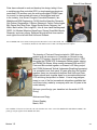
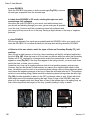
Foreword
By Sharon Readey
This foreword is my attempt to condense nearly 20 years of CCR
development history into a few paragraphs whilst making sure
everyone who deserves it gets the credit they’re due. I’ll do my best.
Peter Readey
Photo: Dan Burton
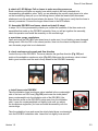
When Peter Readey first got involved in diving back in the late
1980’s he realized that cold European waters although teaming
with life and wrecks, were not conducive to fighting off narcosis
and getting the best bottom times. So he did what any qualified
engineer would do and looked at ways to improve his hobby. His
helium habit (quite expensive in the UK back then) was disguised
with his welding products, but even then it was sizeable enough
he realized there had to be a better way. More research put
him together with Stuart Clough of Carmellan Research. He
purchased a highly modified Rexnold 15.5 and discovered what
most rebreather divers were facing back then – a distinct lack of
water-proof-ness, delicate technology and dated performance.
Pete in Kraken (Sept 27-Oct 1, 1992). Project to video a sunken vessel in the Baltic Sea with Rob Palmer, utilizing Pete’s Marine
Engineer qualifications. Video evidence indicated deliberate scuttling.
But engineers are a resourceful group and they like nothing better than
to design a better mousetrap, or in this case redesign a rebreather.
Working with Stuart throughout the early to mid 1990’s, refining and
redesigning, they did everything they could to bring rebreathers to
the sport market, or as Michael Menduno put it “the second coming”
(because CCRs had made a brief foray into the “professional diver”
market in the late 1960’s- early 1970’s). These were heady start-up
days, when people started to come out of hiding and confess to their
accomplishments, mixed gas, technical diving, computer generated
decompression software and AquaCorps/Tek Shows. Much hard work
done then by those pioneers did not always result in the rewards that
they may have been due, but their efforts grew the market and we have
all profited from the fruits of their labours.
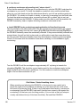
Pete and Dr Brad Carte in Drager SMS2000 (Dec 1992-Jan 1993), Discovery Bay Marine Lab, Jamaica, during testing. SmithKline
Beecham contracted PRISM to dive the “Twilight Zone” in remote locations looking for organisms which could help in cancer cures
etc.
xiv
Version 1.0
Prism 2 User Manual
Peter has continued to work and develop his design, taking it from
a variable mass flow controlled SCR, to simple analogue electronic
controlled CCR and then onto the multi-mode digital PRISM Topaz.
As a result, he has worked with some of the brightest and best
in the industry, from Stuart Clough at Carmellan Research, Iain
Middlebrook/HSM Engineering, Dr Bill Hamilton/Hamilton Research,
Rob Palmer, Dragerwerks, Fullerton Sherwood, Carlton Technologies,
Billy Deans/ Key West Diver, Wings Stocks/Ocean Odyssey, Hal
Watts, Barb Lander, Dick Long/DUI, John & Jean Lamb/Vandergraph,
DDRC, AII, Michael Menduno/AquaCorps, Steven Stuart/Mid-Atlantic
Research, and many others. Entwined through all that time was the
work right at the start with Bob Hollis and Oceanic.
Pete in PRISM SCR (June 19994) at Diving Diseases Research Center, Ft Bovisands, UK. Getting ready for manned testing, scrubber durations, WOB tests and chamber runs to 300ft with independent test subjects.
The teaming of Pete and Oceanic started in 1992 when he
worked as a sub-contractor to Carmellan on Oceanic’s early
Phibian CCS system, through it’s initial chamber tests in 1993
alongside the PRISM SCR, subsequent Phibian dealer training
and DEMA/Tek Shows. More recently between 2008 and 2011,
Peter and Bob worked together on Oceanic’s US Navy project,
the ATUBA (Advanced Tactical Underwater Breathing Apparatus).
It is somewhat ironic that nearly 20 years after they first worked
together, these two innovative principles, Bob Hollis and Peter
Readey should work together again on a recreational/technical
CCR and bring that product to market. It has a long pedigree,
based on one of the first recreational rebreathers available that
is still here today, made by a company with over 40 years in the
scuba industry.
We hope you will enjoy your transition into the world of CCR
Diving.
Welcome and Enjoy.
Sharon Readey
March, 2012
Pete in Phibian CCS (1993-4) Cornwall, UK. After chamber tests in Nov 1993 of the PRISM SCR and Phibian at DDRC, this
prototype was put together for the DEMA/Tek shows.
Version 1.0
xv
Prism Topaz photographs
All Photos courtesy of Steam Machines, Inc.
Above: Pete and his son Christian
on a dive in La Paz, Mexico.
Photo: Kenny Schneider
Below: Manned testing of the
Prism Invader at NEDU, 2002.
Sharon Readey modeling an early
Prism nicknamed “Kermit”.
Front view.
Photo: Matt Elder
Kermit. Back view.
Pre-breathing the rig. Manned
Testing of the Prism Invader at
NEDU, 2002.
Pete hanging in the green of
Gold-diggers Quarry, Cornwall
wearing a Prism semi-closed RB.
Photo: Dan Burton
Kenny Schneider wearing a Prism
Invader, a militarized Topaz.
Top: American Diving’s Prisms.
Bottom: Kevin Rottner with analog
meter
Photo: Robert Landreth
Peter diving an early Cochran
Electronic Prism in 1995
Peter taking Dr. Neil Polack and
Dr. Dick Vann for their final certification dive.
Photo: Matt Elder
Photo: Wes Skiles
Photo: Peter Readey
Prism 2 User Manual
Part 1
System Overview
Indo Steps
Version 1.0
Matthew Addison
1
Prism 2 User Manual
Design Philosophy
The Prism family of rebreathers has a long and illustrious history, and it is considered one of
the foundation platforms of the modern day electronically controlled “sport” rebreather.
The Prism 2, like its forerunner the Prism Topaz, is a digitally controlled electronic closed
circuit rebreather with split front-mounted over the shoulder counterlungs. It incorporates a
radial design scrubber for the best possible duration and work-of-breathing. All gas delivery
systems on the Prism 2 have both automatic and manual function, as well as an option for a
Constant Mass Flow orifice, classing it as a hybrid type rebreather (hCCR).
Manual Control or Computer Control?
One of the ongoing debates when discussing rebreather safety is whether manually controlled
or electronically controlled rebreathers are safer. From the day in 1995 when Prism Topaz
class #1 was held in Hermosa Beach, CA, students were taught to “fly” their rebreathers
manually by watching their secondary analog displays and manually injecting oxygen and
diluent as needed.
From day one, Prism students were taught that the primary control system was always the
divers brain. It wasn’t until the last dive of the last day of class that students were told, “OK,
you can turn on your electronics and experience a computer controlled dive”.
Diving with the computer monitoring the oxygen and the user keeping an eye on everything
with (at that time) a wrist-mounted primary display and analog secondary sure kept us busy,
but we quickly realized that the computer was a LOT better at closely maintaining a set point!
We also realized that our instructor had trained us to be manually controlled rebreather divers
with the safety of computer over-watch.
Why two independent monitoring systems in one rebreather? Simply put, electronics, batteries
and wiring combined with salt water (or even fresh water) do not work well together. While
we can seal circuit boards and wiring interfaces against water intrusion, rebreathers should
have a diver accessible compartment to change batteries, and because of this need for
accessibility, flooding can occur.
This is the Achilles heel of rebreathers with on-board electronics. Any time an O-ring sealed
Compartment is unsealed, the potential for debris to get on the O-ring and cause the
compartment to flood during the next dive is increased.
So, with two separate systems onboard with separate battery compartments, if one battery
compartment floods and destroys the battery, we simply switch to the other monitoring system
to safely end the dive. When our dive is over, we dispose of the wiring harness and battery,
clean the compartment and put in a fresh battery and new O-ring(s).
2
Version 1.0
Prism 2 User Manual
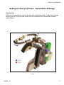
Getting to know your Prism - Schematics & Design
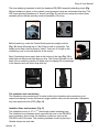
The Gas Path
The Prism 2 incorporates an over-the-shoulder split counterlung design. The gas flows through
the loop from left to right shoulder as has become a standard in the recreational rebreather
market (Fig. 1).
Fig. 1
Version 1.0
3
Prism 2 User Manual
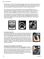
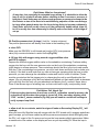
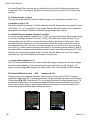
Oxygen and the exhalation side of the loop
Pure oxygen injection into the system, whether manually or electronically,
is injected into the exhalation side of the breathing loop (Fig. 2). This
design insures that a diver can never inadvertently get a high PO2 dose
of oxygen while diving, and that oxygen has plenty of time to properly mix
with the loop gas and thereby avoid potentially dangerous O2 spikes.
Fig. 2
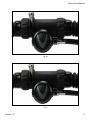
The Over Pressure Valve (OPV) (Fig. 3) The OPV acts automatically to protect the user
from lung injuries caused by excessive pressure in the breathing loop. Being placed on the
exhalation counterlung along with the manual oxygen addition valve also insures that, should
the manual oxygen addition valve (Fig. 4) ever experience a free flow, the free flowing oxygen
will exit the system through the OPV before traveling through the loop and significantly raising
loop PO2. This gives the diver time to take corrective action. Exhaled gas, and any solenoidinjected oxygen enter the head at the exhaust plenum just prior to the scrubber basket. (See
O2 addition valve (Fig. 6) exploded diagram on the following page).
Fig. 3
Fig. 4
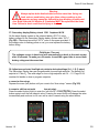
Fig. 5
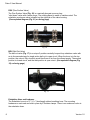
Exhaust Plenum (Fig. 5)
Once the exhaled gas enters the head, it travels into the exhaust plenum, which is also where
O2 injected by the solenoid enters the breathing loop. The exhaust plenum sealing gasket sits
in a groove at the end of the exhaust plenum facing the scrubber basket. The Red CO2 sealing
gasket must be in place at all times!
WARNING
Breathing from the Prism 2 without the Red CO2
Seal in place will result in 100% gas bypass of the
scrubber.
4
Version 1.0
Prism 2 User Manual
Fig. 6A
Fig. 6
Version 1.0
5
Prism 2 User Manual
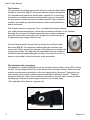
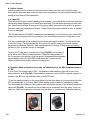
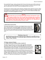
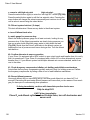
The Scrubber
The gas leaves the exhaust plenum and enters the radial scrubber basket
through its center tube (Fig. 7). As the gas radiates outwards through the
CO2 absorbent and towards the bucket walls, exhaled CO2 is chemically
removed in an exothermic reaction and any added oxygen is mixed with
the loop gas as it travels through the scrubber granules. Upon exiting the
scrubber, the heated gas enters the thermal air jacket area between the
basket and bucket.
Fig. 7
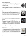
The air jacket serves two purposes: First, it insulates the scrubber material
from colder external temperatures, which helps increase the efficiency of the scrubber.
Secondly, the moisture in the heated gas exiting the scrubber condenses
along the bucket walls as the gas cools, dropping the overall humidity of
the gas entering the oxygen sensors’ area.
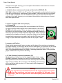
From the thermal jacket, the gas flows up through the scrubber basket
flow vanes (Fig. 8). This restriction creates higher gas velocities in the
sensor area, further dropping the dew point of the gas prior to reaching the
oxygen sensor faces. By using natural condensation along the surface of
the bucket wall and manipulating gas velocities in the area around the O2
sensors, we are able to keep the sensors as dry as possible.
Fig. 8
The inhalation side counterlung
The inhalation counterlung (Fig. 9) houses the automatic diluent addition valve (ADV). Having
the ADV on the inhalation side of the loop makes sense for several reasons. Should the loop
contents ever become questionable or the diver begins feeling “abnormal”, flushing the loop
with a known normoxic gas is always recommended while switching to bailout*. Therefore,
having the diluent as close to the mouthpiece as possible is the best way to insure that fresh
breathing gas of known and safe oxygen content is only a breath away.
*(Not applicable if the diluent is a hypoxic mix)
Fig. 9
6
Version 1.0
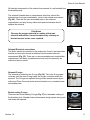
Prism 2 User Manual
The hose attaching hardware for both the head and DSV/BOV assembly attaching points (Fig.
10) are welded into place, so they cannot come loose and cause an unintended loop flood. The
DSV hose attaching hardware is a “keyed” part (Fig. 11) and will only accept the correct hose
assembly elbow, thereby avoiding incorrect assembly of the loop.
Fig. 10
Fig. 11
Behind each lung, under the Fastex Buckle panel are weight pockets
(Fig. 12) which will accept up to 5 lbs/2.3kg of hard or soft weight. The
weight pouch flap is held in place by Velcro. There are 2 D-rings on the
counterlung, one on the side and one at the bottom.
Each Counterlung has a water drain at the bottom of the lung (Fig. 13) to
drain fluids as they accumulate during a dive. The Faxtex clip panel on the
back of the counterlung contains 2 fastex clips for clipping the counterlungs
to the harness and one chest strap with clip.
Fig. 13
Fig. 12
Fig. 14
The exhalation side counterlung
The Exhalation side counterlung is of similar build to the Inhalation side counterlung in all
respects excepting it houses the manual oxygen addition valve and the automatic, adjustable
loop over-pressure valve (OPV) (Fig. 14)
Inhalation Hose and hardware (Fig 15)
The Inhalation hose is a 15” X 11/2” fixed-length rubber breathing hose.
The Inhalation hose hardware which connects the hose to the DSV/BOV
and counterlung, also houses the inhalation mushroom valve on the
DSV/BOV side of the hose. The mounting hardware is held in place by 2
Oeteker clamps on each side.
Version 1.0
Fig. 15
7
Prism 2 User Manual
DSV (Dive Surface Valve)
The Dive Surface Valve (Fig. 16) is a neutrally buoyant one-way loop
“shut down” valve with a water purge. The rotating barrel is made of stainless steel. The
exhalation mushroom valve is seated on the right side of the valve housing.
(See exploded diagram (Fig 18 ) on facing page)
Fig. 16
BOV (Bail-Out Valve)
The bail out valve (Fig. 17) is a unique 3-position neutrally buoyant loop shutdown valve with
an in-line second stage for single action bail out to open circuit. When the lever is in the top
position, the valve is fully closed to avoid free flows of air from the diluent supply. The second
position is closed circuit, and the third position is open circuit. (See exploded diagram (Fig
19) on facing page)
Fig. 17
Exhalation Hose and hardware
The Exhalation hose is a 15” X 11/2” fixed-length rubber breathing hose. The mounting
hardware on each end are held in place by 2 Oeteker clamps. There is no mushroom valve in
the exhalation hose.
8
Version 1.0
Prism 2 User Manual
Fig. 18
Fig. 19
Version 1.0
9
Prism 2 User Manual
Battery Compartment cover
The battery compartment cover (Fig. 20) is made of glass reinforced ABS.
The cap utilizes two O-rings for redundant water tightness, a radial seal
on the lip of the cap and a compression seal on the top of the battery
compartment housing.
There is a pressure relief valve built into the top of the cover to vent
excess pressure should the battery compartment flood. If the pressure
release valve (red) were ever to actuate, you would need to replace it prior
to immersing the unit (see maintenance section).
Fig. 20
Battery compartment
The battery compartment (Fig. 21) holds two sets of batteries: two 9V
alkaline batteries wired in parallel which powers the solenoid, and one
SAFT 3.6 volt LiON (Lithium Ion) that powers the LED Primary Display.
The sealed bulkhead power connector at the bottom of the compartment is
a female molex connector. A foam insert holds the batteries in place.
Fig. 21
O2 sensors, sensor holders, connector, pins
The 3 O2 sensors are located in a chamber above the scrubber basket
(Fig. 22).
This insures a low condensation area and consequently drier O2 sensors.
The sensors are Analytical Industries PSR-11-39-MD which have an
operating range of 8.5mV-14mV in air and 40.6mV-67mV at 100% O2 at
1 atm pressure. The holders are removable to give users better access
to the O2 sensors, wiring harness and connector pins. The holders are
Fig. 22
manufactured from a soft silicone material to help protect the O2 sensors
from vibration and minor impact forces.
See “Taking Care of your Oxygen Sensors” on page 21 for more information.
Solenoid (Fig. 23)
The Prism 2 solenoid is a low power (0.65 watt) normally closed
electromagnetic valve mounted in an isolated compartment in the head.
The normally closed solenoid will only allow gas to flow when an electrical
current is applied and the valve is momentarily opened. Operational failure
or loss of adequate voltage to open the solenoid valve will keep oxygen
from flowing into the system. Oxygen flows from the solenoid body directly
into a channel that leads from the solenoid into the exhaust plenum in the
head.
10
Fig. 23
Version 1.0
Prism 2 User Manual
All electrical components of the solenoid are external to, and isolated from
the breathing loop.
The solenoid chamber has an overpressure valve that, should the
solenoid ever loose gas containment, vents to the outside environment
(Fig 24.). There are no user serviceable parts in the solenoid
compartment, and only factory authorized repair technicians should
replace the solenoid.
Fig. 24
Field Notes
Because the oxygen solenoid is a safety-critical part,
should it malfunction, it must be replaced by a factory authorized service center, never repaired.
Solenoid Electrical connections
The Molex electrical connector for the solenoid is found in the electronics
module and connects through a bulkhead into the sealed solenoid
compartment (Fig. 25). There are no user serviceable parts inside either
compartment, and these compartments should only be opened by an
authorized service center.
Fig. 25
Solenoid O-rings
The solenoid is sealed by two O-rings (Fig. 26). The outer O-ring seals
out water, and the inner O-ring keeps the oxygen contained within the
solenoid. The O-rings are replaced during routine annual service by an
authorized Prism 2 service center and are therefore not considered userserviceable parts.
Fig. 26
Bucket sealing O-rings
There are two bucket sealing O-rings (Fig. 27) for redundant sealing of
the breathing loop. Standard user maintenance during system set-up and
tear-down are required.
Fig. 27
Version 1.0
11
Prism 2 User Manual
The Solenoid and the PID controller
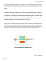
The Prism 2 Solenoid is controlled by state-of-the-art PID Control loop feedback circuitry (The
Controller). The PID Controller makes calculations based on an error value which is calculated
as the difference between a measured process variable (how much oxygen is in your loop) and
a desired setpoint (the O2 setpoint). It also considers the history of what has occurred previously,
and makes predictions about what may occur in the future, constantly making adjustments to it’s
algorithms accordingly. Sometimes called a “Three Term Controller”, the P, I and D stands for
Proportional - Integral - Derivative.
A familiar example of a control loop is the action taken when adjusting hot and cold faucets
(valves) to maintain the water at a desired temperature. This typically involves the mixing of two
process streams, the hot and cold water. The person touches the water to sense or measure
its temperature. Based on this feedback they perform a control action to adjust the hot and cold
water valves until the process temperature stabilizes at the desired value.
The sensed water temperature is the process variable or process value. The desired temperature
is called the setpoint. The input to the process (the water valve position) is called the manipulated
variable. The difference between the temperature measurement and the set point is the error
and quantifies whether the water is too hot or too cold and by how much.
After measuring the temperature, and then calculating the error, the controller decides when to
change the tap position and by how much. When the controller first turns the valve on, it may
turn the hot valve only slightly if warm water is desired, or it may open the valve all the way if
very hot water is desired. This is an example of a simple proportional control. In the event that
hot water does not arrive quickly, the controller may try to speed-up the process by opening up
the hot water valve more-and-more as time goes by. This is an example of an integral control.
Making a change that is too large when the error is small is equivalent to a high gain controller
and will lead to overshoot. If the controller were to repeatedly make changes that were too large
and repeatedly overshoot the target, the output would oscillate around the setpoint in either a
constant, growing, or decaying sinusoid. If the oscillations increase with time then the system is
unstable, whereas if they decrease the system is stable. If the oscillations remain at a constant
magnitude the system is marginally stable.
12
Version 1.0
Prism 2 User Manual
In the interest of achieving a gradual convergence at the desired temperature, the controller
may wish to damp the anticipated future oscillations. So in order to compensate for this effect,
the controller may elect to temper its adjustments. This can be thought of as a derivative control
method.
If a controller starts from a stable state at zero error, then further changes by the controller will
be in response to changes in other measured or unmeasured inputs to the process that impact
on the process, and hence on the process variable. Variables that impact on the process other
than the manipulated variable are known as disturbances. Generally controllers are used to
reject disturbances and/or implement setpoint changes. Changes in feed water temperature
constitute a disturbance to the faucet temperature control process.
In theory, a PID controller can be used to control any process which has a measurable output, a
known ideal value for that output and an input to the process that will affect the relevant process
value. PID controllers are used in industry to regulate temperature, pressure, flow rate, chemical
composition, speed and practically every other variable for which a measurement exists.
A Typical Solenoid Loop Feedback Circuit*
*Source: Wikipedia
Version 1.0
13
Prism 2 User Manual
Bucket latches
There are 4 Nielson Sessions 300 series Stainless Steel locking latches mounted on a
stainless steel band (Fig. 28) that hold the bucket securely onto the head assembly. While two
latches will hold the bucket securely, it was felt that redundancy here was critical.
Fig. 28
Basket spring on bucket
The absorbent basket is pressure-sealed onto the Red CO2 Seal under
the head by the bucket spring assembly (Fig. 29) at the bottom of the
bucket. The spring creates the seal between the basket and Red CO2
Seal and also reduces vibration on the basket during transit.
Fig. 29
Absorbent basket assembly
The absorbent basket is comprised of five main pieces (Fig. 30). The basket outer cage that
supports the nylon absorbent-retaining mesh, a screw-in center tube, which also supports the
nylon mesh and a screw-on cover. Two foam pads must be installed top and bottom prior to
filling the absorbent basket. The bottom pad has a larger center diameter hole than the top
pad. The foam pads impede the flow of gas against the smooth surfaces of the basket top and
bottom, hindering any potential gas channeling in these areas.
Fig. 30
14
Version 1.0
Prism 2 User Manual
The gas flow vanes built into the top of the scrubber basket create an area of increased gas
velocity within the O2 sensor area of the head, reducing the dew point of the gas around the O2
sensors. The reduction in condensing humidity in this critical area helps reduce the potential
for water to condense on the surface of the hydrophobic membrane of the O2 sensor.
Backplate
The Hollis Prism 2 can be outfitted with an industry standard technical style backplate. The
user can specify either a stainless steel (Fig. 31) or anodized aluminum backplate when
ordering their rebreather. The style of threading the webbing for the backplate is left to user
preference.
Fig. 31
O2 and Diluent first stages
All Prism 2 first stages (Fig. 32) have been oxygen cleaned and
assembled in a clean room environment with specially designed
materials, halocarbon-based lubricants and color-coded for easy
identification on and off the Prism 2 chassis (green=O2, Black=Dil). In
non-CE countries, they come outfitted with 300 BAR/4500 PSI DIN
connections and custom designed port blocks with 4 low pressure and 1
high pressure ports. This custom design does away with the need to add
in fail points such as hose swivels. The working Intermediate pressure of
both first stages is 130 to 150psi / 8.96 to 10.34 bar.
Fig. 32
All First stages are equipped with pressure relief valves (Fig. 33). The
valves reduce the likelihood of an uncontrolled increase in intermediate
pressure causing a free-flow of gas into the breathing loop. The first stage
pressure relief valve is not a user serviceable part.
The oxygen feed lines to the solenoid and manual O2 addition valve
incorporate in-line flow restrictors to meter the flow of oxygen into the
breathing loop. The restrictors must not be removed.
Fig. 33
Gas Cylinders
The Hollis Prism 2 will accommodate all sizes of cylinders commonly used on rebreathers.
Version 1.0
15
Prism 2 User Manual
Fitting your Prism 2
Your Prism 2 rebreather should be fitted to you with the same attention as you would any
other fine (and very expensive) custom-made piece of clothing. A properly fitted rebreather will
perform more consistently with better all around breathing characteristics, have less hydrostatic
imbalances in all diving positions, less strain and fatigue on spinal musculature and better diver
trim while diving.
The fitting process begins before you even set-up the Prism 2. First you must assess your
body type, as that will give you a starting place for making close approximations to what will be
the final, best fit.
The standard counterlung yoke fits a wide range of body types, and generally anyone between
5ft to 6ft tall with a standard torso will find a best fit using the standard counterlung yoke. At
the upper ranges of that measurement, a person with a long torso, or anyone taller than 6’ will
probably find that the Long yoke works best for them. If you have any questions, or need help
finding which set-up works best for you, ask a Prism 2 Instructor, or go into your local Hollis
dealer. They will be more than happy to help you get your rebreather properly fitted.
Once you have decided which yoke should work best, you will begin testing out the different
variables such as backplate position (2 available), Wing position (2 available) and three
positions on the yoke, which will dictate where the counterlungs sit on your chest.
First look at the backplate. The harness webbing should be adjusted so the top of the
backplate plate sits about 1 inch or so below your shoulders. Next, put the counterlungs on the
yoke. Take the assembly and put it on so the yoke hangs over the backplate while holding the
counterlungs on your chest. The DSV/BOV assembly breathing hose holes should be level with
your collar bones.
16
Version 1.0
Prism 2 User Manual
Proper fit is the first element in a rather complex dance with physics. These few pointers
should give you a good starting place in custom fitting the Hollis Prism 2 for best fit. Don’t be
afraid to experiment with placement as the ultimate goal is diver comfort. Once you have a fit
that you feel will work for you in the water, we need to examine how and where to distribute
any weight you will require to get you the best in-water “stability” possible.
Version 1.0
17
Prism 2 User Manual
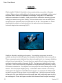
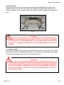
Stability
by Gerard Newman
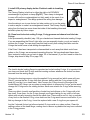
What is stability? Briefly, it’s the ability to choose and maintain your position in the water
column. When we have a stable platform for diving we are more comfortable, in better control
and better able to observe our underwater surroundings. Diving with a CCR adds some
additional considerations for stability. Ideally, we should be stable when swimming (dynamic
stability) and when hovering (static stability). We have better control over our stability when
we assume prone (horizontal) trim in the water with our fins flat. This increases our vertical
drag (helping to maintain our vertical position in the water column) and decreases our
horizontal drag (as when swimming) (fig S1).
Fig. S1
Stability is affected by weighting and buoyancy. Our weighting components include the
cylinders we choose to dive with, lights, fins, backplates and lead ballast that we carry with us.
These components may be distributed from side to side and head to toe. Improper distribution
will result in non-horizontal trim. Too much lead at our waist will tend to drag our hips down
resulting in a head-up position in the water (fig S2). Fins that are too light will result in a feetup position. Divers often instinctively compensate for weight placement problems by arching
their backs to maintain trim. The objective is to allow proper trim with a relaxed posture in the
harness. Of course proper weighting is key – we should be able to maintain a 10 foot stop
with no gas in the wing and a comfortable amount of gas in our exposure suit. With the CCR
we have to account for the gas volume in our breathing loop. I typically recommend starting
with an extra 4 lbs over what the diver would normally wear with a single tank open circuit rig
as a starting point. Divers with larger or smaller tidal volumes will need to adjust accordingly.
18
Version 1.0
Prism 2 User Manual
Our buoyancy components include our exposure suit, our wing, and our counterlungs.
Minimizing the gas volumes in each will go a long way towards minimizing the effects of
Boyle’s Law. The larger the gas bubble, the harder it is to control. The shallower you are, the
more pronounced the effects of Boyle’s Law – careful attention to controlling the gas volumes
in our counterlungs, wing and our exposure suit on ascent is critical. Adding or removing small
amounts of gas and allowing time for the change to take effect is the key to controlling our
buoyancy (Fig. S2, S3).
Fig. S2
Fig. S3
Counterlung position should be such that they are as close to your
lungs as possible, both in the vertical and horizontal planes (Fig.
S4). This will minimize static lung loading and decrease the work of
breathing. The bottoms of the counterlungs should be secured to the
waist strap to hold them in place when they are inflated and become
buoyant. For most divers the elbows on the counterlungs should be
positioned at the collarbones, with the chest strap tightened to control
their horizontal position. Gas volume in the counterlungs will affect
both your buoyancy and trim. Too much gas in the counterlungs will
result in head-up trim; too little will result in head-down trim (and
difficulty taking a full breath). With practice one can become proficient
at adding and removing gas from the breathing loop to maintain
horizontal trim and neutral buoyancy.
Fig. S4
The wing may be positioned to increase buoyancy towards our head or our feet if needed to
adjust our trim. Weights can be placed near the shoulders to provide a counterbalance to the
counterlungs and help keep us prone in the water with minimal effort.
Version 1.0
19
Prism 2 User Manual
The backplate should be positioned such that the top of the plate is easily reachable with
the tips of your fingers if you swing your arms back with your elbows next to your ears. On
most people this will position the backplate at the top of the scapulas. Straps should be
loose enough to allow full range of movement of your arms across the chest and allow you to
“chicken wing” into and out of the harness. The crotch strap should be adjusted to keep the rig
stable – tight, but not too tight. If the crotch strap is pulling the waist strap down then it is too
tight and needs to be lengthened (Fig. S5).
Fig. S5
A very helpful technique is to have someone shoot some video of you while hovering and
while swimming. Reviewing this video can help identify where your buoyancy or trim needs
adjusting. A good Intro to Tech instructor can also be very helpful.
20
Version 1.0
Prism 2 User Manual
Taking Care of your Oxygen Sensors
The best way to care for an exotic animal is to first acquire some knowledge about it’s likes
and dislikes, and environments that will help the animal thrive. Likewise, having a working
knowledge of what is and is not good for the health of your oxygen sensors will help you
take the best care possible of them, and hopefully avoid unnecessary mid-season damage
replacement. Here are some important questions, and their answers.
What is a galvanic O2 sensor?
An oxygen sensor is a very small electrochemical generator. Some people equate them to a
battery, but that comparison is largely incorrect since a battery does not produce electricity
as the O2 sensor does, and the O2 sensor does not store electrical energy as a battery does.
Understanding that the O2 sensor is more like a delicate power-generating machine than a
robust Duracell D battery is your first clue in understanding how they should be handled.
What materials are used to manufacture the Analytical Industries PSR-11-39-MD
sensors?
The body of the sensor is made of High-Density Polyethylene (HDPE). The membrane on the
front of the sensor is a thin Teflon gas permeable membrane. The internal components are
comprised of a lead anode, a precious metals-plated cathode, a base pH electrolyte consisting
of mostly water and a bit of Potassium Hydroxide. A printed circuit board (PCB) with resistorthermistor temperature compensation circuitry is heat sealed to the outside back of the sensor.
What environmental conditions are best and worst for the O2 sensor?
Your “PSR” series O2 sensors are happiest between 32oF/0oC and 122oF/50oC. Operating
or storing the O2 sensor above 122oF/50oC will prematurely dry out the electrolytic fluid
and destroy the sensor. Operating or storing the O2 sensor below 32oF/0oC will freeze the
electrolytic fluid causing expansion damage to the Teflon membrane and possibly leakage of
the electrolyte upon thawing, thereby destroying the sensor.
How does changes in ambient temperature influence the O2 sensor’s performance?
Temperature influences the signal output at a rate of 2.54% per °C. Gradual ambient changes
in temperature can be maintained within +-2% accuracy by processing the signal output
through the resistor - thermistor temperature compensation network. Rapid changes of
Version 1.0
21
Prism 2 User Manual
59oF/15°C require 45-60 minutes for the compensated signal output to equilibrate, e.g. the
electronic thermistor reacts immediately to offset the change in the sensor, but the sensing
membrane and electrolyte reacts at a much slower rate.
Because of the exothermic (heat generating) reaction of CO2 scrubbing taking place next to
the sensor housing during diving operations, it is important that you calibrate the sensors close
to “room temperatures” (60oF/16oC – 80oF/27oC) so you are not temporarily outside of the
59oF/15oC “rapid compensation” range while diving.
How does pressure influence the oxygen sensor’s performance?
Pressure influences the signal output on a proportional basis. The sensor is accurate at any
constant pressure up to 30 ATM provided the sensor (front and rear membranes) is pressurized
and decompressed gradually (similar to human lungs). The membranes, especially the front
sensing membrane, do not tolerate rapid change in back pressure or vacuum. Normal diving
operations will not generate pressures excessive to which the sensor is designed to operate.
If you use a pressure vessel to check voltage limiting, it is important that you slowly bleed
off the accrued pressure in the vessel after the checks are completed. The optimal analysis
pressures range is 5-30 PSIG, up to 100PSIG, with a flow rate of 1-2SCFH. The longer you
keep the cells pressurized, the slower you need to bleed off pressure. This procedure may
sound familiar to divers.
What is the maximum altitude the oxygen sensor can be exposed and still function?
The oxygen sensors have been tested up to 20,000 Ft / 6096M with no error.
Does moisture or water affect the oxygen measurement?
If moisture or water is present in the gas stream it will not damage the oxygen sensor or
analyzer, but it can collect on the sensor’s sensing membrane, thus blocking the flow of gas.
What happens when the O2 sensor has been exposed to water.
The collection of condensation on the sensing surface of the sensor (standing water) reduces
the signal output. Once either drying or gravity removes the standing water, the signal output
will return to normal within 30 seconds. For example, a thin layer of water over the sensing
surface will reduce the signal output of a sensor from 11.8mV to 10.1mV within 20 minutes;
22
Version 1.0
Prism 2 User Manual
remove the standing water and the signal output returns to 11.8mV in 30 seconds. The design
of the Prism 2 makes condensation collecting on the face of the sensor such that the signal
can be degraded in a normal diving position very unlikely. Note: Salt water can corrode or
bridge electrical connections resulting in erratic oxygen readings.
Can a sensor be contaminated by carbon dioxide (C02) gas, reducing the sensor life?
Exposure of the sensor with its base electrolyte to carbon dioxide (CO2) gas or acid gases will
produce crystal-like deposits on the cathode, which reduces the surface area of the cathode
and the corresponding signal outputs. This effect is cumulative, cannot be reversed and
can dramatically reduce the expected sensor life. This means that attempting to “Push the
Scrubber” beyond its factory-stated duration, or breathing into a loop without active scrubber
material installed will shorten the life of your O2 sensor.
Can the oxygen sensor be damaged if dropped or if the rebreather is dropped?
Absolutely! Sensors are fragile and can be damaged in a number of ways. Dropping a sensor
by itself or while mounted in the rebreather can result in: (a) broken wires; (b) broken electrical
connections; (c) dislodging the anode and either breaking a connection or creating an internal
short as the loose anode comes in contact with the cathode connection. If the motion stopforce is applied onto the sensor face, the liquid electrolyte can be forced onto the Teflon
membrane, stretching the material and destroying the sensor. Testing has shown that dropping
a sensor one time from 3ft/1m onto a carpeted concrete slab can result in an immediate 25100% reduction in signal output.
Types of forces known to cause sensor damage while housed in a rebreather include, (but
are not limited) to transportation shock (baggage handler throwing distance competitions,
driving over rough terrain, jolts during heavy seas and extreme motor vibrations). It is always
recommended that you remove the sensors from the rebreather if it may be subject to any of
the above conditions.
Can I touch the Teflon membrane with my finger? How do I clean the sensor and
contacts?
No, you must not touch the sensor face with anything, especially your fingers. Fingers have
oils on them even when freshly washed, and the oil permanently clogs the membrane,
destroying the sensor. If salt has dried on the sensor face, you can gently pour a bit of distilled
water on the membrane and allow it to air dry. Never use any cleaning solutions on the sensor
face. You may use an electronics contact cleaner such as DeOxIt Gold on the contact pins, but
use it sparingly and wipe off all residual cleaner before use.
Version 1.0
23
Prism 2 User Manual
What is the expected oxygen sensor life?
The operational life of the PSR-11-39-MD sensors are calculated as one year from the date
they are put in service. The warranty is one year from the date they were shipped from the
factory. Do not attempt to extend the life of the sensors past one year from the date they were
put in service. Doing so can result in incorrect or no signal output which can lead to serious
injury or death.
What is the recommended storage temperature?
During a “diving season” (if one exists for you) the oxygen sensors, when stored, should be
kept in a cool, ambient, unsealed environment to insure they are immediately operational. If
you will be storing the sensors for a month or more, you can place them in an airtight container
in a refrigerated environment that is kept above 34oF/0.1C to insure that the electrolyte does
not freeze (see “Environmental Conditions” above). While this will not extend the operational
life of the sensor, it may reduce response time degradation during the latter part of its
16-month service life.
After storage, you will need to acclimate the sensors by placing them in air at room
temperature for 24 hours prior to putting the sensors back in service. Failure to acclimate the
sensors after storage can cause the sensors to read incorrectly and possibly lead to injury or
death.
Are the O2 sensors date coded?
Oxygen sensors have a finite life. Understanding the date code is vital to getting the benefit of
the warranty period. As an example, the serial number 10734789 breaks down as follow: Digit
#1 a (1) denotes the year of manufacture as 2011; digits #2, #3 (07) indicate July as the month
of manufacture; the remaining digits are sequential for uniqueness. As the result of a number
of issues related to the use of aged sensors, Analyitical Industries has added a “DO NOT
SELL AFTER: (date)” to the sensor’s labeling which is 4 months from the date of manufacture
along with a requirement that the cells service life must not exceed 16 months from the date of
manufacture.
You must NEVER use oxygen cells past beyond their expiration
date, no matter if the output is still within the sensor’s stated
operational parameters.
24
Version 1.0
Prism 2 User Manual
Part 2
Displays and
Electronics
Operation
Matthew Addison
Version 1.0
25
Prism 2 User Manual
PRIMARY DISPLAY WIRING
WARNING
Do not attempt to unscrew the Primary Display wiring from the
head.
THIS IS NOT A THREADED PART!
Attempting to unscrew or remove the wiring from the head will
destroy the wiring and quite possibly the hardware sealing
surface in the head.
SECONDARY DISPLAY WIRING
WARNING
Do not attempt to unscrew or remove the Secondary Display
wiring from either the head or the Secondary Display.
THESE ARE NOT THREADED PARTS!
Attempting to unscrew or remove the wiring from the head or
the Secondary Display will destroy the wiring and quite possibly
the hardware sealing surface in the head or Secondary Display
housing.
26
Version 1.0
Prism 2 User Manual
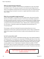
Displays and Controller
There are two separate diver display systems in the Prism 2. The LED Primary Display and
the wrist mounted Secondary Display.
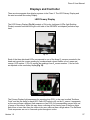
LED Primary Display
The LED Primary Display (Fig 34) consists of 3 bi-color (red/green) LEDs (light Emitting
Diodes) mounted on either the right or left side of the DSV/BOV mouthpiece just below eye
level.
Fig. 34
Each of the three bicolored LEDs corresponds to one of the three O2 sensors mounted in the
head and reports the oxygen reading by numbered and colored flashes of red, green and
orange. LED number 1 (L to R) reports the readings from O2 sensor number 1, and so forth
as reported on the secondary display(Fig 35).
Fig. 35
The Primary Display light sequences for reporting loop PPO2 to the user is called “Smithers
Code” and are the same for each LED. Each LED reports only on the O2 sensor it represents,
so the user will see a different flash sequence of an LED if its corresponding sensor drifts out
of range of the others. While this may seem confusing at first, having one of the three lights
flash more or less often than the others is far more obvious than a single alarm. The Smithers
Code sequences are run in 5-second cycles throughout a dive.
Version 1.0
27
Prism 2 User Manual
The PO2 light states encountered on the LED Primary Display shown in the table below and
are as follows: While in dive mode reporting loop PO2, 1.0 ATM O2 is considered the mid-line
for the LED Primary Display. When the PO2 is between 0.95 and 1.05 PPO2, you will see one
orange flash every five seconds (the orange color is created by both the red and green colors
of the LED flashing simultaneously {see field note, pg 29}). When the PO2 in the loop is below
the mid-line of 1.0 PO2, you will get one red flash for every 0.1 atm O2 below, and one green
flash for every 0.1 atm O2 above the centerline of 1.0 PO2 (Fig. 36).
PO2
1.6
1.5
1.4
1.3
1.2
1.1
0.95 - 1.05
0.9
0.8
0.7
0.6
0.5
0.4
Accept Cal
Lost Signal
LEDs Check
Battery Low
Color
# Flash / 5 Sec
Green
6
Green
5
Green
4
Green
3
Green
2
Green
1
Orange
1
Red
1
Red
2
Red
3
Red
4
Red
5
Red
6
Red
Solid - 5 Sec
Green\Red
Continious
Green/Red
Once only
Orange
Solid - 30 sec.
Cycle
5 sec
5 sec
5 sec
5 sec
5 sec
5 sec
5 sec
5 sec
5 sec
5 sec
5 sec
5 sec
5 sec
Once after calibration
Continious
Once at turn-on
Once at turn-on
Fig. 36
LEDs check at turn on
When you first turn on the Primary Display, the green and red LEDs will each flash once. This
is a test to insure that all LEDs are working correctly. Once this test has competed, the system
will check the battery voltage and if it is low, will flash a battery warning (see Low battery
warning). If the battery is operational, the electronics will begin displaying the appropriate O2
cell information.
WARNING
USE ONLY NAME-BRAND BATTERIES (DURACELL, EVEREADY, etc)
OFF-BRAND / DISCOUNT BATTERIES ARE ACCEPTABLE TO POWER TOYS
AND FLASHLIGHTS BUT HAVE NO PLACE IN LIFE SUPPORT GEAR AND
MUST NEVER BE USED TO POWER ANY COMPONENT OF YOUR PRISM 2.
(Refer to full battery warnings on page V)
28
Version 1.0
Prism 2 User Manual
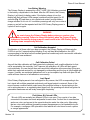
Low Battery Warning
The Primary Display is powered by a SAFT LiON 3.6V AA battery mounted
in the battery compartment in the head. After the LED check, the Primary
Display, it will check its battery state. If the battery charge is low, the
display will flash all three LEDs orange (combined red and green) for 30
seconds (Fig. 37) and then go into operational mode if enough battery
charge remains for it to do so. Low battery warnings will only occur once at
power-on and will not be repeated until the LED Primary Display power is
cycled off and on again.
Fig. 37
WARNING
You must change the Primary Display battery when you receive a low
battery warning. Failure to change the battery when the Primary Display
indicates a low battery during power-on could result in the LED Primary Display
shutting down unexpectedly mid-dive.
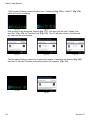
Cell Calibration Accepted
If calibration of all three cells have been accepted, the Primary Display will illuminate the
3 LEDs in red for 5 seconds without blinking. If any cell has failed calibration, the LED
corresponding to the failed cell will oscillate green/red continiously until a successful calibration
of that cell has been achieved.
Cell Calibration Failed
Any cell that fails calibration will flash green/red continiously until a valid calibration for that
cell is accepted by the controller. If all 3 sensors fail calibration, all LEDs will flash green/
red continiously. It is rare that all three cells would fail calibration at the same time if they are
within their expected service life, not damaged by mishandling and the loop is fully flushed with
oxygen. Ususally, an accidental calibration in air or an incomplete loop flush with pure O2 will
cause all three sensors to fail calibration concurrently.
Lost Signal
If the Primary Display were to lose cell signal for any reason, the LED corresponding to the
lost signal will oscillate green/red continiously until signal output is restored. Some of the
more common conditions which could cause this would be broken or shorted wiring in the
cell or wiring harness or a completely dead (aged) cell. An operating cell which has gotten its
permeable membrane wet will rarely lose signal completely.
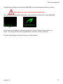
Field Notes: Bi-Colored LEDs
“Bi-color LEDs are actually two different LEDs in one case. They consist of two dies
connected to the same two leads antiparallel to each other. Current flow in one direction
emits one color, and current in the opposite direction emits the other color. Alternating
the two colors with sufficient frequency causes the appearance of a blended third color.
For example, a red/green LED operated in this fashion will color blend to emit a yellow
or orange appearance”
Version 1.0
29
Prism 2 User Manual
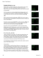
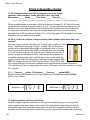
Secondary Display
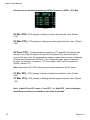
The display has five areas. There are three title areas and three
data display areas (Fig 37).
DEPTH TIME STOP TIME
34.7 15 24 1
O2/HE NDL TTS
CC 21/OO O 15
Across the top line is the title for the first row of information. This
area only changes during the display of the dive log. The first data
Fig 37
area shows depth, battery warning, dive time, ascent rate, first stop depth, and first stop time.
Fig 37 is showing a depth of 34.7 meters, a low battery alarm, 15 minute dive time, a 3 meter per
minute ascent rate, and a stop at 24 meters for 1 minute.
The low battery indicator glows yellow after the battery is less than 3.28V for 30 seconds. Below
3.15V the battery indicator will flash red. You will need to change your battery immediately.
It is recommended to change your battery when the battery indicator steadily glows yellow.
The ascent rate indicator shows 6 levels of ascent rate. Each block represents either 10 fpm or
3 mpm. 1, 2 and 3 bars will be green, 4 and 5 bars will be yellow, 6 bars will be red. When the
ascent rate is greater than 6 bars, the whole block will be filled in red, and it will flash.
If you are above the indicated stop depth, the stop depth will flash red.
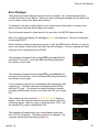
The second data line shows the three O2 sensor readings (Fig. 38). If a
sensor is voted out, it will display the current value, but it will flash yellow
and the value will not be considered in the average PPO2. This area will
also display fixed
PPO2.
DEPTH TIME STOP TIME
34.7 15 24 1
1.3 1.3 1.3
CC 21/OO O 15
O2/HE NDL TTS
Fig 38
The next area is the title for the bottom line. This title changes frequently in the menu system to
provide additional information about the bottom line. The last line shows that the computer is in
closed circuit (CC) mode with a gas containing 21% oxygen and 0% helium.
If there is a gas programmed in the current mode (OC or CC) that would normally be used at the
current depth, the system will flash the gas contents in red to remind you to either switch gases,
or remove the gas if you aren’t using it.
In addition, there is a context sensitive area at the bottom which is implemented when cycling
through menus.
The no decompression limit (NDL) is zero since we are in decompression, and the time to surface (TTS) is 15 minutes.
The computer works in both metric and imperial for depths and temperatures. The depth shows
a decimal point when the depth is between 0 and 99 meters. It shows no decimal point if the
display is set to feet.
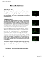
To turn the computer on, press both the MENU and the
SELECT buttons at the same time.
30
Version 1.0
Prism 2 User Manual
Buttons
MENU (Left)
• From the default display, pressing MENU brings up the menu.
• Once in the menu system, MENU moves to the next menu item.
• If the current function is an edit, pressing MENU increments the current display.
SELECT (Right)
• In the menu system, the select button saves the current value or executes the command.
• Out of the menu system, the select button brings up information displays.
BOTH BUTTONS
• When the computer is off, pressing MENU and SELECT at the same time will turn the computer on.
The left button (MENU) can be used to scroll through the menu.
When the “Switch Setpoint” menu item is displayed, MENU will
move to the “Select Gas” menu item (Fig 39).
The right button (SELECT) is used to accept the current choice.
Pressing SELECT with this screen displayed will enter the Select
Gas function (Fig 40).
DEPTH TIME STOP TIME
O
.85 .86 .84
Switch to -> 1.3
Fig 39
DEPTH TIME STOP TIME
O
.85 .86 .84
Select Gas
Fig 40
DEPTH TIME STOP TIME
In the “Select Gas” function, MENU increments the gas number
(Fig. 41).
O
.85 .86 .84
Set A1 CC 21/OO
Cancel
Fig 41
Select
DEPTH TIME STOP TIME
SELECT would select closed circuit gas 2 (Fig. 42).
O
.85 .86 .84
Set A2 CC 21/OO
Cancel
Version 1.0
Fig 42
Select
31
Prism 2 User Manual
When the system is not in a menu, pushing SELECT will bring up
information displays with various dive status information. This is
the first information display showing the diluent PPO2 amount, the
current CNS loading, the setpoint (if applicable), and the average
PPO2 being used for decompression calculation (Fig. 43).
DEPTH TIME STOP TIME
O
.85 .86 .84
.21 O .19Fig.OO43
DilPPO2 CNS SP AvgPPO2
Menu
The system is designed to make the selection of the common operational functions while
diving easy. The menu selections are separated into two sets. The “Operation” menu is to
provide easy access to commonly used functions. The “Setup” menu is to change system settings.
The system will continue to read the sensors and update the sensor display while you are in
the menu system.
If no buttons are pushed for a minute, the menu system will time-out. Anything that had been
previously saved will be retained. Anything that was in the middle of editing will be discarded.
A key characteristic of the menu system is that it is adaptive. It uses the information
that it knows about its current state to only ask questions or offer menu items that
make sense given the current situation.
For example, on the surface, the first menu item you will see is Turn Off. During a dive,
the Turn Off menu item doesn’t appear.
The second menu item is Calibrate. That item only shows on the surface. External
PPO2 monitoring must be left “ON” (the System Default) or the secondary will not
report the output of the O2 cells.
32
Version 1.0
Prism 2 User Manual
The full menu structure is below:
•
•
•
•
•
•
Turn Off
Calibrate
Switch Setpoint
Select Gas
Switch Open Circuit / Closed Circuit (Open Circuit / Semi-Closed Circuit)
Dive Setup
• Edit Low Setpoint
• Edit High Setpoint
• Define Gases
• Dive Planner
• NDL Display
• External PPO2 Monitoring
• Brightness
• Dive Log
• Display Log
• Upload Log
• Edit Log Number
• Clear Log
• Setpoint -> .19
• System Setup
• Dive Setup
• OC Gases
• CC Gases
• O2 Setup
• Auto SP Switch
• Display Setup
• System Setup
• Advanced Configuration
• Salinity
• Title Color
• OC Show PPO2
• End Dive Delay
• CC Min PPO2
• CC Max PPO2
The Turn Off, Calibrate, Dive Log, Setpoint -> .19, and System Setup menus are only available
on the surface. This is the menu during a dive:
• Switch Setpoint
• Select Gas
• Switch Open Circuit / Closed Circuit (Open Circuit / Semi-Closed Circuit)
Version 1.0
33
Prism 2 User Manual
• Dive Setup
• Edit Low Setpoint
• Edit High Setpoint
• Define Gases
• NDL Display
• Brightness
The status screens are:
• Gases, no-decompression limit and time to surface
• Diluent PPO2, CNS, and average PPO2
• Oxygen sensor millivolts
• Max depth, average depth, average atmospheres
• Water temperature, current Gradient Factor, current fixed Oxygen
• GF99, decompression ceiling, time-to-surface in 5 minutes and time-to-surface
• Battery voltage
• Pressure
• Date and time
• Surface interval
• Serial number and version number
Basic Setup
Before using the computer there are several things that need to be configured. This is not an
exhaustive list of the prerequisites for diving the system, but a suggestion of key tasks.
Calibrate the oxygen sensors.
In the System Setup menu set the units to metric or imperial, also set the date and time.
Enter the gases that you will use for the closed circuit portion of your dive, and/or enter the
gases for you will use for open circuit.
The system will use the gases that are available in the order of oxygen content during the Time
To Surface (TTS) prediction. The system will use the next available gas that has a PPO2 of
less than 1.0 for closed circuit diving.
If the computer is switched to open circuit during a dive, the system will calculate the TTS
based on the configured open circuit gases that are available. It will use the next available gas
that has a PPO2 of less than 1.6 for open circuit diving.
NOTE: These gases are used automatically only for TTS predictions. The gas used to
calculate the current tissue load and the current ceiling is always the gas actually selected by
the diver.
34
Version 1.0
Prism 2 User Manual
Display Elements Descriptions:
Closed-Circuit Partial Pressure of O2 (PP02):
The Secondary will Flash Red PPO2 when less than 0.4 or greater than 1.6.
Shows internal sensor PPO2 (will show three values).
Shows the current setpoint, which is the PPO2 at which the Secondary assumes the breathing loop is being maintained.
Displays 3 sensors.
DEPTH TIME STOP TIME
O
.35 .36 .34
CC 21/OO O O
O2/HE NDL TTS
Displays PPO2 in Yellow when sensor is voted out.
Displays FAIL when calibration is not valid.
When in OC mode, the sensor values continue to display.
This shows the state of the breathing loop, but not what is
currently being breathed.
DEPTH TIME STOP TIME
O
.85 .56 .84
CC 21/OO O O
O2/HE NDL TTS
DEPTH TIME STOP TIME
O
Fail Fail Fail
CC 21/OO O O
O2/HE NDL TTS
DEPTH TIME STOP TIME
O
O2/HE NDL TTS
CC 21/OO O O
Version 1.0
35
Prism 2 User Manual
Fraction Inspired O2 (FiO2) (Fig. 44):
The fraction of the breathing gas composed of O2. This value is independent of pressure.
Fig 44
Ascent Bar graph (Fig. 45-47):
Imperial: Shows 1 bar for every 10 feet per minute (fpm) of ascent rate.
Metric: Shows 1 bar for every 3 meters per minute (mpm) of ascent rate.
Green when 1 to 3 bars, Yellow when 4 to 5 bars, and Flashes Red when 6 bars or more.
Fig 45-47
Battery Symbol (Fig. 48-49):
When the battery is good, the battery symbol does not display.
Displays Yellow when the battery needs to be changed.
Flashes Red when the battery is dangerously low and must be replaced immediately.
Depth (Fig. 50):
Shows the depth in the currently selected units (feet or meters). Meters are displayed with 1 decimal place up to 99.9
meters. Feet are never displayed with a decimal place.
Note: If the depth shows a Flashing Red zero, then the
depth sensor needs service (Fig. 51).
Dive Time (Fig. 52):
The length of the current dive in minutes. Does not display when not diving.
Stop Depth and Time (Fig. 53):
Stop – the next stop depth in the currently selected units (feet or meters).
Time – the time in minutes to hold the stop.
Will Flash Red when you ascend shallower than the current stop (Fig. 54).
FiO2
.21
Fig48-49
DEPTH
117
Fig 50
DEPTH
O
Fig 51
TIME
25
Fig 52
STOP TIME
15O 25
Fig 53
DEPTH TIME STOP TIME
9O 11O 1OO 25
Fig 54
Note on 10ft/3m last stops: The Secondary uses 10ft/3m last
stops. You may perform 20ft/6m stops with no penalty, since
the Secondary Display is always calculating tissue loading
at your actual depth. The only difference is that the predicted
time-to-surface will be shorter than the actual TTS since offgasing is occurring slower than expected.
36
Version 1.0
Prism 2 User Manual
Average Depth (Fig. 55):
Displays the average depth of the current dive, updated
once per second.
When not diving, shows the average depth of the last dive.
Average Depth in Atmospheres (AvgATM) (Fig. 56):
The average depth of the current dive, measured in absolute
atmospheres (i.e. a value of 1.0 at sea level).
AVG
5O
Fig 55
ft
AvgATM
1.3
Fig 56
When not diving, shows the average depth of the last dive.
Circuit Mode (Fig. 57-59):
The current breathing configuration. One of:
OC = Open circuit
CC = Closed circuit
SC = Semi-closed circuit
Current Gas (O2/He) (Fig. 60):
The current gas shown as a percentage of Oxygen and Helium. The remainder of the gas is assumed to be Nitrogen.
In closed circuit mode, this gas is the diluent. In open circuit
mode this is the breathing gas.
Flashes Red when there is another programmed gas that is
more appropriate at the current depth than the current gas
(Fig. 61).
No Decompression Limit (NDL) (Fig. 62):
The time remaining, in minutes, at the current depth until
decompression stops will be necessary.
Displays in Yellow when the NDL is less than 5 minutes (Fig.
63).
Once the NDL limit has been exceeded, this value can be
set to optionally display other information. These options are:
CEIL: The current ceiling in the currently selected units (feet
or meters). Flashes Red if you ascend shallower than the
current ceiling (Fig. 64).
GF99: The raw percentage of the Buhlmann allowable supersaturation at the current depth (Fig. 65).
@+5: The time-to-surface (TTS) if you were to stay at the
current depth for 5 more minutes (Fig. 66).
Version 1.0
OC
CC
SC
Fig 57-59
O2/HE
CC 21/OO
Fig 60
O2/HE
CC 21/OO
Fig 61
NDL
2O
Fig62
NDL
Fig 63
5
CEIL
Fig 64
8O
GF99
8O%
2O
Fig 65-66
@+5
37
Prism 2 User Manual
Time-to-Surface (TTS) (Fig. 67):
The time-to-surface in minutes in the current circuit mode.
Assumes an ascent rate of 30 feet per minute (10 meters per
minute), that stops will be followed and programmed gases
will be used as appropriate.
Maximum Depth (Fig. 68):
The maximum depth of the current dive.
When not diving, displays the maximum depth of the last dive.
TTS
35
Fig 67
MAX
26O
CNS Toxicity Percentage (Fig. 69):
Central Nervous System oxygen toxicity loading percentage.
Setpoint:
The current PPO2 setpoint. Displays in Yellow when the setpoint is 0.19 (Fig. 71).
11
CNS
1OO
Fig 69-70
SP
Fig 71
Average PPO2:
The average PPO2 of the current breathing gas (Fig. 72).
AvgPPO2
In OC mode, displays in Flashing Red when less than 0.19 or greater than 1.65 (Fig. 73).
AvgPPO2
In CC mode, displays in Flashing Red when less than 0.40
or greater than 1.6. In CC mode, averages all sensors that
are not voted out (Fig. 74).
AvgPPO2
Diluent PPO2 (Fig. 75):
Only displayed in CC mode. Displays in Flashing Red when
the partial pressure of the diluent is less than 0.19 or greater
than 1.65.
Gas PPO2 (Fig. 76):
Only displayed in OC mode. Displays in Flashing Red when
less than 0.19 or greater than 1.65.
Gradient Factor (Fig. 77):
38
CNS
Flashes Red when 100 or greater (Fig. 70).
The CNS percentage is calculated continuously, even when
on the surface and turned off. Removing the battery will reset
the CNS percentage.
ft
Fig 68
Fig 72
Fig 73
Fig 74
.6
.98
.16
.36
DilPPO2
Fig 75
.99
GasPPO2
Fig 76
.99
GF
3O/85
Fig 77
Version 1.0
Prism 2 User Manual
Decompression and Gradient Factors
The basic decompression algorithm used for the computer is Buhlmann ZHL-16C. It
has been modified by the use of Gradient Factors that were developed by Erik Baker.
We have used his ideas to create our own code to implement it. We would like to give
credit to Erik for his work in education about decompression algorithms, but he is in no
way responsible for the code we have written.
The computer implements Gradient Factors by using levels of conservatism. The levels
of conservatism are pairs of number like 30/85.
The default of the system is 30/85. The system provides several settings that are more
aggressive than the default.
Don’t use the system until you understand how it works.
Fig 78
Graph from Erik Baker’s “Clearing Up The Confusion About Deep Stops”
Version 1.0
39
Prism 2 User Manual
Gradient Factors Explained
By Kevin Watts
This primer attempts to provide a user’s view of gradient factors, an Erik Baker derived method
of calculating decompression schedules.
Back to Bühlmann
Everything in the gradient factor decompression algorithm revolves around Dr. Albert A.
Bühlmann’s tissue model. Currently this means 16 hypothetical tissue compartments that are
constantly tracked during a dive in order to determine each tissue compartment’s inert gas
pressure.
As you ascend, all those tissue compartments start to release pressure (off- gas). The question
is “How fast can you let those tissue compartments off-gas?”
Bühlmann answered that question by coming up with an “M-value”. Basically, an M-value is a
maximum pressure value (different for each depth and tissue compartment) that tells you, if you
exceed that value, your chances of getting decompression sickness are greatly increased.
A natural ascent strategy then would be to move up in the water column until the pressure in your
tissue compartments just reaches Bühlmann’s M-value and then let your tissue compartments
off-gas a bit, rise to the next level, etc. In this strategy, you would keep going up in such a way
that you never let your tissue compartments exceed Bühlmann’s M-value.
Unfortunately, decompression illness does not exactly track Bühlmann’s M-values. A greater
potential for decompression illness occurs at and above the pressures represented by M-values
and the potential lessens when divers never reach Bühlmann’s M-values.
Enter Gradient Factors
Gradient factors (GFs) were invented to let the diver choose how fast, and how close their
tissue compartments get to Bühlmann’s M values.
Gradient factors are calculated as follows:
Tissue Compartment Pressure - Ambient Pressure
Gradient Factor= ___________________________________________
MValue - Ambient Pressure
What does this formula tell us?
First, the gradient factor formula tells us that at a Gradient Factors of 1.0 (GF=1.0), you are at
Bühlmann’s M-value. Therefore, staying at or below GF=1.0 seems important. Second, it tells
us that when our tissue compartment pressure just reaches ambient pressure, then the GF=0.0.
Another ascent strategy, then, might be to shoot up to a GF=0.8 and ascend in such a way as to
40
Version 1.0
Prism 2 User Manual
not exceed that value. In this way you know that your tissue compartments are never over 80%
of the distance between ambient pressure and Bühlmann’s M-value. In essence, you have a 20%
safety margin on Bühlmann’s M-value. Dive computers implementing gradient factors usually let
you set two gradient factor parameters. Moving straight to GF=0.8 would be equivalent to setting
your dive computer to 80/80.
Erik Baker’s Strategy
Erik baker didn’t like the idea of ascending directly to a GF close to Bühlmann’s M-value. Instead,
he said, “let’s all ascend first to a lower GF, then slowly move to higher GFs”. So, let’s say you
want to first ascend to a GF=0.30, and then slowly move to reach GF=0.85 as you surface. This
setting on your gradient factor computer is 30/85. The Prism 2 secondary uses 30/85 as its
default setting.
So what is happening when you use a GF setting of 30/85?
First, your dive computer allows you to ascend until the pressure in your tissue compartments first
reaches a GF-0.30. This means your tissue compartment pressure is 30% of the way between
ambient pressure and Bühlmann’s M-value. Then you sit there until your tissue compartments
drop enough pressure, so that you can ascend to your next stop.
How much pressure must leave your tissue compartments before you can ascend?
Assume you hit your first stop (GF=0.30) at 110ft. We now have two known points. Point 1 is
(110,0.30), that is, at 110ft we are at GF of 0.30. Point 2 is (0, 0.85) that is, at the surface, we
want to be at GF=0.85. A natural way to ascend (and this is what Baker did) is to create a line
from those two known points and ascend in such a way that you never exceed the GF generated
by that line.
Once you determine your two points, the formula for the maximum GF at any depth is:
HighGF - LowGF
MaxGF = HighGF + _______________________________ Current Depth
HighGFDepth - LowGFDeptrh
But since the high gradient factor is reached at the surface, HiGFDepth=0. So,
HighGF - LowGF
MaxGF = HighGF + ________________________ Current Depth
LowGFDepth
Version 1.0
41
Prism 2 User Manual
Therefore, if you hit your first GF=0.30 at 110ft, then your LowGFDepth=110. Before you can
ascend to 100ft you must let off enough tissue compartment pressure so that when you arrive at
100ft the GF of your tissue compartments does not exceed 0.35 calculated as:
0.85 - 0.30
MaxGF = 0.85 + ________________
100
110
You can ascend to 90ft when your tissue compartments let off enough pressure at your 100ft
stop so that when you reach 90ft your tissue compartments does not exceed 0.40 calculated as
0.85 - 0.30
MaxGF = 0.85 + _________________
90
110
The GF method allows you to ascend by walking that line all the way to the surface.
Summary
If you understood the above explanation, then you see why divers say that setting your GF
parameters to 10/90 or 10/80 etc. helps generate deep stops. The low GF of 10 means a stop
must be generated when your tissue compartments are only 10% of the way between ambient
pressure and Bühlmann’s M-value, rather than 30% if you were to set the low GF to 30. Simply,
the GF line just starts deeper.
The gradient factor method is a natural extension of Bühlmann’s tissue compartment model.
Divers using computers implementing the gradient factor method should understand how
modifying their GF parameters would alter the decompression profiles. You must consider
altering your GF parameters based on dive characteristics, your physical condition, and your
general attitude toward the risk of decompression illness. The gradient factor method provides
the diver substantial flexibility in controlling their decompression profiles. Your responsibility is
to choose the factors appropriate for you.
For more information on gradient factors and M-values, please refer to Erik Baker’s excellent
articles, “Clearing up the confusion about deep stops” and “Understanding M-values”, available
on the web.
42
Version 1.0
Prism 2 User Manual
The VPM-B algorithm requires an activation code which cen be purchased at additional
expense. To activate the VPM-B decompression algorithm, contact your Hollis Dealer.
VPM-B/GFS EXPLAINED
a) VPM-B Profile
b) VPM-B/GFS Profile
· Gradient Factor Surfacing (GFS) adds conservatism to the shallow stops of a VPM-B
profile.
· In the pure VPM-B profile the Buhlmann (ZHL-16C) Gradient exceeds 90%.
· On the VPM-B/GFS profile, the shallow stops have been lengthened because the gradient
is limited to 90%.
· GFS adds more time to dives that require more decompression. Dives with deco times
under 45 minutes are typically not affected.
· The GFS gradient factor can be adjusted from 70% to 99%. The default is 90%.
NOTE:
For VPM-B, higher conservatism values are more conservative. The most aggressive
settings is 0, and the most conservative is +5. The default is +3.
For the GFS value, higher values are less conservative. The most aggressive setting is
99%, and the most conservative is 70%. The default is 90%.
Version 1.0
43
Prism 2 User Manual
Pressure (Fig. 79):
The pressure in millibars. Two values are shown, the surface
(surf) pressure and the current (now) pressure.
Pressure mBar
1O13 Fig 79
1O11
Surf
Now
The current pressure is only shown on the surface (i.e. when
not diving).
The surface pressure is set when the Secondary Display is
turned on. If the Altitude setting is set to SeaLvl, then surface
pressure is always 1013 millibars.
Temperature (Fig. 80):
The current temperature in degrees Fahrenheit (when depth
in feet) or degrees Celsius (when depth in meters).
TEMP
73`F
Fig 80
External Voltage (Fig. 81):
The external voltage of the solenoid battery.
Ext V
Fig 81
Internal Voltage (Fig. 82):
The Secondary Display’s internal battery voltage. Displays
in Yellow when the battery is low and needs replacement.
Displays in Flashing Red when the battery is critically low
and must be replaced as soon as possible.
Millivolts (Fig. 83):
The raw millivolt readings from the O2 sensors.
Date and Time (Fig. 84):
In the format mm/dd/yy
24-hour clock time.
Serial Number (Fig. 85):
Unique serial number identifier for every Secondary Display.
Version (Fig. 86):
The version number indicates the features available on the Secondary Display.
The last two numbers are the firmware version.
Surface Interval (Fig. 87):
The time in days, hours and minutes since the last dive
ended. Reset when the battery is removed.
Int V
3.55
Fig 82
MilliVolts
42.O 46.Fig
O 43.83O
Date
Time
O2/16/1OFig16:8431
Serial No
1234ABCDFig 85
Version
2OOOO32Fig 86
Surface Interval
O OFigO87
Days
44
7.6
Hr
Min
Version 1.0
Prism 2 User Manual
Example Dive
This is an example of the displays that might be seen on a dive. This example shows a complicated dive with multiple Closed Circuit (CC) gases and multiple Open Circuit (OC) bail-out
gases. A normal, single gas CC or OC dive wouldn’t have any button pushes at all, so there
isn’t much to show.
The first step is to calibrate (Fig. 88). Since we are on the surface and not diving, MENU will
bring up “Turn Off”, then “Calibrate.” Once the loop is flushed with oxygen, SELECT will bring
up the confirmation display (Fig. 89), and another SELECT will calibrate (Fig. 90).
DEPTH TIME STOP TIME
DEPTH TIME STOP TIME
Cal. milliVolts
O
.85 .86 .84
Calibrate
45.1 46.3 44.O
.85 .86 .84
Cal. @ PPO2= .98
Cancel
Fig 88
O
.98 .98 .98
CC 21/OO O O
O2/HE NDL TTS
Calibrate
Fig 89
Fig 90
Next, we check the closed circuit gases that we have programmed. Entering the gas selection
function by pressing SELECT with the “Select Gas” menu item showing (Fig. 91) will display
the first CC gas that is available (Fig. 92). MENU will increment to the next gas available.
Another MENU takes us back to the “Select Gas” menu item. Those are the only two gases
configured. We SELECT gas number 2, Trimix 10/50 (Fig. 93).
DEPTH TIME STOP TIME
DEPTH TIME STOP TIME
DEPTH TIME STOP TIME
O
.98 .98 .98
Select Gas
O
.98 .98 .98
Set A1 CC 21/OO
Next Gas
Select
O
.98 .98 .98
Set 2 CC 1O/5O
Cancel
Select
The system will use both of these gases for our dive when calculating the TTS. It assumes a
diluent switch at a PPO2 of 1.0. That means that it will assume that you have switched to an
air diluent at 124 feet. This is only for TTS. The computer will always use the currently selected gas for tissue loading calculations.
Then we switch to open circuit to look at our bail-out gases. Flipping through the gases with
MENU shows that we have three gases available (Fig. 91-93). (Whether they are appropriate
gases is a subject for one of the web forums.)
DEPTH TIME STOP TIME
O
.98 .98 .98
Set A1 OC 99/OO
Next Gas
Version 1.0
Fig 91
DEPTH TIME STOP TIME
DEPTH TIME STOP TIME
Select
O
.98 .98 .98
Set 2 OC 5O/2O
Next Gas
Fig 92
Select
O
.98 .98 .98
Set 3 OC 14/55
Cancel
Select
Fig 93
45
Prism 2 User Manual
These are the gases that will be used to estimate TTS in the event that you switch to open circuit during a dive. The computer will assume that you will switch gases when the PPO2 of the
next available gas is less than 1.61.
Automatic decisions of when to switch gases for the TTS calculation means that it is very easy
to set up your CC and OC gases. There is no need to enter a depth or a PPO2 to switch gas.
There is no need to keep track of which gases are turned on and off in which mode.
If a gas is available in the CC gas list it will be used in CC, and it will be used at an appropriate depth. The same is true for OC. It is always configured correctly if you actually have the
gases you have created.
If it is necessary to switch to OC while diving, 3 button pushes will do it (Fig. 94). You will be
switched to OC and will be using the gas that has the highest PPO2 less than 1.61. Your OC
gas list is likely very different from your diluent gas list, but all of the OC gases are automatically selected and available.
Now switch back to closed circuit and start the dive (Fig. 95).
DEPTH TIME STOP TIME
O
.98 .98 .98
Switch CCFig-> 94OC
DEPTH TIME STOP TIME
O
.98 .98 .98
CC 1O/5OFig O95 O
O2/HE NDL TTS
We have reached a depth now that will incur decompression soon
(Fig. 96). The NDL is 8 minutes, and the TTS is 4 minutes. The
TTS just reflects the ascent time at 30 fpm.
The computer has automatically switched to the high setpoint. This
can be disabled if automatic setpoint switching isn’t required.
DEPTH TIME STOP TIME
126 2
1.3O 1.29 1.29
CC 1O/5OFig8 964
O2/HE NDL TTS
DEPTH TIME STOP TIME
We are now at our maximum depth. Our first stop is at 90 feet (Fig.
97).
257 8 9O 1
1.31 1.29 1.22
CC 1O/5OFigO 9723
O2/HE NDL TTS
DEPTH TIME STOP TIME
The diver is ascending to the 90 foot stop. Note the ascent rate
indicator showing a 30 fpm / 10 mpm ascent rate. Although the
ascent rate is 30 fpm now, during the 7 minute ascent, the diver
ascended slower than was predicted, and now there is a 100 foot
stop (Fig. 98).
46
98 15 1OO 1
1.3O 1.29 1.29
CC 1O/5O FigO 98
22
O2/HE NDL TTS
Version 1.0
Prism 2 User Manual
DEPTH TIME STOP TIME
But the diver missed the stop, and has ascended to 95 feet. At this
point, the stop depth and time is flashing red to show that the depth
is above the recommended stop (Fig. 99).
95 15 1OO 1
1.3O 1.29 1.29
CC 1O/5O O 22
O2/HE NDL TTS
Fig 99
DEPTH TIME STOP TIME
The diver switches to the other programmed CC gas, air. Note that
if you change the diluent on the computer you must flush the loop
to change the diluent in the loop. At the same time the 100 foot
stop clears. It is common for the first stops to clear in less than a
minute. They mainly just slow down the ascent (Fig. 100).
At 60 feet a problem develops that causes the diver to bail out to
open circuit. The first push (#1) on MENU brings up Select Gas
(Fig. 101).
95 15 9O 1
1.3O 1.3O 1.29
CC 21/5O O 22
O2/HE NDL TTS
Fig 100
DEPTH TIME STOP TIME
6O 19 6O 1
1.3O .99 1.29
Select GasFig 101
DEPTH TIME STOP TIME
The second push (#2) brings up Switch CC -> OC (Fig. 102).
6O 19 6O 1
1.3O 1.OO 1.29
Switch CCFig-> OC
102
DEPTH TIME STOP TIME
A push on SELECT does the switch (#3). The system has switched
the gas set from the closed circuit gas set to the open circuit gas
set, picked the gas with the highest PPO2 less than 1.6, and recalculated the decompression based on the new profile (Fig. 103).
6O 19 6O 1
1.3O 1.O9 1.29
OC 5O/2O
O 36
Fig 103
O2/HE
NDL TTS
DEPTH TIME STOP TIME
At 20 feet, one push on MENU brings up select gas (Fig. 104).
2O 25 2O 3
.87 .95 .79
Select Gas
O2/HE
NDL TTS
Fig 104
DEPTH TIME STOP TIME
A push on SELECT enters the select gas menu, and another SELECT picks the O2. Since the gases are sorted by oxygen content,
O2 is the first gas offered (Fig. 105).
Version 1.0
2O 25 2O 3
.87 .95 .79
Set 1 OC 99/OO
Cancel
Fig 105
Select
47
Prism 2 User Manual
Menu Reference
Turn Off (Fig. 106)
The “Turn Off” item puts the computer to sleep. This menu item
will only appear if the water contacts are dry on controllers. While
sleeping, the screen is blank, but the tissue contents are maintained for repetitive diving. The “Turn Off” menu item will not appear during a dive. Turn off time is user selectable in the Advanced
Configuration menu.
Calibrate (Fig. 107)
This will calibrate the sensor displays to oxygen. Flood the breathing loop with pure oxygen, SELECT with “Calibrate” in the display,
and the confirmation message will display. On the top line, the millivolt reading will show. Good sensors should be in the range of 35
- 60 mV at sea level in 100% oxygen. The allowable millivolt range
for calibration in the computer programming is 30 - 70 mV. This
scales with percentage of oxygen and barometric pressure.
Pressing the MENU button will prevent the calibration. Pressing
SELECT will calibrate the sensor displays. The displays should
now all read .98. If any display shows FAIL, the calibration has
failed because the mV reading is out of range. (Fig. 108-109)
The system defaults to a calibration gas of 98% oxygen. This is to
compensate for the difficulty in completely filling the loop with 100%
oxygen and also to allow for water vapour. If you are using a calibration kit with no water vapour and 100% O2, you can set the calibration gas to 100. It can also be set to other values if pure oxygen
is not available.
The calibration takes into account the altitude at which the computer was turned on. For example, if the altitude was 885 mBar or .87
ATA, then with a 98% calibration gas, the sensors would calibrate to
.85.
DEPTH TIME STOP TIME
O
.98 .98 .98
Turn Off Fig 106
DEPTH TIME STOP TIME
O
.85 .86 .84
Calibrate Fig 107
Cal. milliVolts
42 46 25
.85 .86 .62
Cal. @ PO2= .98
Cancel
Fig 108
Calibrate
DEPTH TIME STOP TIME
O
.98 .98 FAIL
CC 21/OO O O
O2/HE NDL TTS
Fig 109
The “Calibrate” menu item will not display during a dive.
48
Version 1.0
Prism 2 User Manual
Calibration Problems
Here are some common calibration problems. In this display, one
sensor is flashing yellow. This shows that the sensor is voted out. If it
comes back within range, it will be voted back in, stop flashing yellow
and return to green (Fig. 110).
DEPTH TIME STOP TIME
O
.98 .97 1.16
O2/HE NDL TTS
CC 21/OO O O
Fig 110
A failed sensor is a different situation. In this case, the sensor failed
calibration. Changing the sensor won’t make it register again. Once
a sensor has failed calibration, the only way to bring it back is to successfully calibrate. If the computer were to display a value with a new
sensor, it would be a meaningless value without calibration (Fig. 111).
DEPTH TIME STOP TIME
O
.98 .97 FAIL
O2/HE NDL TTS
CC 21/OO O O
Fig 111
If this was the display, it would indicate a faulty sensor. It is not within
the expected range for a sensor in oxygen. Most sensors are designed
to output 10 mV +/- 3 mV in air. If the output is linear, then that translates to a range of 30 to 70 as valid mV readings in 98% oxygen. The
computer will refuse to calibrate outside that range (Fig. 112).
Cal. milliVolts
42 46 25
.98 .98 .62
Cal. @ PO2= .98
Cancel
Fig 112
Calibrate
DEPTH TIME STOP TIME
Three sensors all showing FAIL is usually caused by an accidental
calibration in air. A failed calibration can only be fixed by performing a
successful calibration (Fig. 113).
O
FAIL FAIL FAIL
O2/HE NDL TTS
CC 21/OO O O
Fig 113
Version 1.0
49
Prism 2 User Manual
External Battery (Solenoid Battery) Alerts
The two 9 volt batteries located in the battery compartment in the head drive the Watt
Miser 0.65 watt solenoid. The operating range of the solenoid is from 9 volt to 7 volt, at
which time the user will get a “low battery” alert on the Secondary Display. The battery is
measured by the computer while the battery is under load. Failure to change the battery
after a “Low Battery” alert will result in the solenoid eventually discontiniung operation.
1
“Low Ext Battery” when battery falls
below operating threshold (7V).
2
After user confirms, the small red
text persists as long as the low battery condition remains.
3
If the battery falls so low that the
solenoid does not fire (or current
falls out of range), a “Solenoid Alert”
occurs.
4
After user confirms, the small red
text persists as long as the solenoid
alert condition remains.
5
If “Ext V” is viewed, it appears in red.
USE ONLY NAME-BRAND BATTERIES (DURACELL, EVEREADY, etc)
OFF-BRAND / DISCOUNT BATERIES HAVE NO PLACE IN LIFE SUPPORT GEAR
AND MUST NEVER BE USED TO POWER ANY COMPONENT OF YOUR PRISM 2.
(See full battery warnings on page V)
50
Version 1.0
Prism 2 User Manual
Switch Setpoint
When SELECT is pushed with either of these displays, the displayed
setpoint on the right will be selected.
During a dive, the “Switch Setpoint” menu item will be the first item
displayed. The “Turn Off” and “Calibrate” displays are disabled (Fig.
114 - 115).
Version 1.0
DEPTH TIME STOP TIME
O
.85 .86 .84
Switch .7Fig-> 1.114
3
DEPTH TIME STOP TIME
O
.85 .86 .84
Switch 1.Fig
3 ->115
.7
51
Prism 2 User Manual
Select Gas (Fig. 116)
This menu item allows you to pick a gas from the gases you have
created. The selected gas will be used either as the diluent in
closed circuit mode, or the breathing gas in open circuit mode.
Gases are always sorted from most to least oxygen content.
Press the SELECT button when “Select Gas” is displayed, and the
first available diluent/gas will be displayed (Fig. 117).
Use the MENU button to increment the diluent/gas to the one you
want, then press the SELECT button to select that diluent/gas (Fig.
118).
If you increment past the number of gases available, the display will
fall back out of the “Select Gas” display without changing the selected gas.
The current gas will flash YELLOW when a more appropriate gas is
defined. Use the “Confirm” button to select a gas. The bottom line
of the display shows the selected gas. An ‘A’ will appear next to the
currently active gas.
DEPTH TIME STOP TIME
O
.87 .86 .84
Select GasFig 116
DEPTH TIME STOP TIME
O
.87 .86 .84
Set A1 CC 21/OO
Next Gas
Fig 117
Select
DEPTH TIME STOP TIME
O
.87 .86 .84
Set 2 CC 1O/5O
Next Gas
Select
Fig 118
Radio Station Gases
The system maintains two sets of gases - one for open circuit and one for closed circuit.
The way they operate is very similar to the way car radios work with AM and FM stations.
When you are listening to an FM station and you push a station selection button, it will take
you to another FM station. If you add a new station, it will be an FM station.
Similarly, if you are in the AM mode, adding or deleting a station would add or delete an AM
station.
With radio station gases, when you are in open circuit, adding, deleting or selecting a gas will
refer to an open circuit gas. Just like the FM stations are selected when your radio is in FM
mode, the closed circuit gases are available in the closed circuit mode. When you switch to
open circuit, the gases available will be open circuit gases.
52
Version 1.0
Prism 2 User Manual
Switch to OC/CC
Depending on the current computer setting, this selection will show
as either “Switch CC -> OC” or “Switch OC -> CC” (Fig. 119-121).
Pressing SELECT will select the displayed mode for decompression
calculations. When switching to open circuit while diving, the most
appropriate open circuit gas will become the breathing gas for
calculations.
At this point, the diver may want to switch to a different gas, but
since the diver may have other things to deal with, the computer will
make a “best guess” of which gas the diver would choose.
DEPTH TIME STOP TIME
O
.85 .86 .84
Switch CCFig-> OC119
DEPTH TIME STOP TIME
O
.85 .86 .84
Switch OCFig-> CC
120
DEPTH TIME STOP TIME
There is also an option to set the computer to calculate
decompression predictions using semi-closed circuit. This is
enabled in the System Setup menu (Fig. 122).
When switching the computer from CC mode to OC mode, the
computer will continue to maintain the active O2 setpoint. You
can manually adjust setpoint after switching the computer to
OC mode to as low as 0.4ata O2.
Dive Setup+ (Fig. 123)
These screens are showing controller displays.
Pressing SELECT will enter the Dive Setup sub-menu.
Low Setpoint (Fig. 124)
This item allows you to set the low setpoint value. It will display the
currently selected value. Values from 0.4 to 1.5 are allowed.
A press of MENU will increment the setpoint.
O
.85 .86 .84
Switch OCFig->121
SC
DEPTH TIME STOP TIME
O
1.3
Switch CCFig->122
OC
DEPTH TIME STOP TIME
O
.85 .86 .84
Dive Setup+
Fig 123
DEPTH TIME STOP TIME
O
.85 .86 .84
Edit Low SP O.7
Next
Fig 124
Edit
DEPTH TIME STOP TIME
Press the SELECT button when “Edit Low SP” is displayed and
the edit display will be shown. It is set at the lowest valid value for
setpoint, 0.4 (Fig. 125).
O
.85 .86 .84
Edit Low SP O.4
Change
Version 1.0
Fig 125
Save
53
Prism 2 User Manual
DEPTH TIME STOP TIME
Another press of MENU will increment it again (Fig. 126).
O
.85 .86 .84
Edit Low SP O.5
Change
If SELECT is pushed, the currently displayed setpoint will be selected, and the display will return to the “Low SP” menu item (Fig. 127).
If the highest allowable value 1.5 has been passed, the value will
return to 0.4.
High Setpoint (Fig. 128)
The high setpoint function works exactly like the low setpoint function.
Save
DEPTH TIME STOP TIME
O
.85 .86 .84
Edit Low SP O.5
Next
Edit
Fig 127
DEPTH TIME STOP TIME
O
.85 .86 .84
Edit High SP 1.3
Next
54
Fig 126
Fig 128
Edit
Version 1.0
Prism 2 User Manual
Define Gas (Fig. 129)
The function allows you to set up 5 gases in Closed Circuit and 5
gases in Open Circuit. You must be in Open Circuit to edit open circuit
gases, and you must be in Closed Circuit to edit closed circuit diluents.
For each gas you can select the percentage of oxygen and helium in
the gas.
DEPTH TIME STOP TIME
O
.85 .86 .84
Define Gas
Next
Define
Fig 129
Pushing SELECT when “Define Gas” is displayed presents the function
to define gas number 1 (Fig. 130).
DEPTH TIME STOP TIME
O
.85 .86 .84
Edit 1 OC 99/OO
Next Gas
Pushing the MENU button will display the next gas (Fig. 131).
Fig 130
Edit
DEPTH TIME STOP TIME
O
.85 .86 .84
Edit 2 OC 5O/OO
Next Gas
Fig 131
Edit
DEPTH TIME STOP TIME
Pushing SELECT will allow you to edit the current gas. The gas contents are edited one digit at a time. The underline will show you the
digit being edited (Fig. 132).
O
.85 .86 .84
Edit 2 OC 5O/OO
Change
Each push of the MENU button will increment the digit being edited.
When the digit reaches 9 it will roll over to 0 (Fig. 133).
O
.85 .86 .84
Edit 2 OC 5O/OO
O
.85 .86 .84
Edit 2 OC 5O/OO
Next
HE%
Fig 134
Next
DEPTH TIME STOP TIME
O
.85 .86 .84
Edit 2 OC 5O/OO
Change
Version 1.0
O2%
Fig 133
DEPTH TIME STOP TIME
Change
Pushing SELECT on the last digit will finish editing that gas and bring you
back to the gas number (Fig. 135).
Any gases that have both oxygen and helium set to 00 will not be displayed in the “Select Gas” function.
Next
DEPTH TIME STOP TIME
Change
Pushing SELECT will lock in the current digit and move on to the next digit
(Fig. 134).
O2%
Fig 132
HE%
Fig 135
Save
55
Prism 2 User Manual
DEPTH TIME STOP TIME
Pushing MENU will continue to increment the gas number (Fig.
136).
O
.85 .86 .84
Edit 2 OC 5O/OO
Change
Note: The “A” denotes the active gas. You cannot delete the
active gas. If you try it will generate an error. You can edit it,
but cannot set both the O2 and He to 00 (Fig. 137).
The computer will display all 5 gas entries available to allow you to
enter new gases.
Pressing MENU one more time when the fifth gas is displayed will
return you to the “Define Gas” menu item (Fig. 138).
HE%
Fig 136
Save
DEPTH TIME STOP TIME
O
.85 .86 .84
Edit A3 OC 14/55
Next Gas
Fig 137
Edit
DEPTH TIME STOP TIME
O
.85 .86 .84
Edit 5 OC OO/OO
Done
Edit
Fig 138
Only enter the gases you are actually carrying on the dive. With radio station
gases, the computer has a full picture of the OC and CC gases you are carrying
and can make informed predictions about decompression times. There is no need
to turn gases off and on when you switch from CC to OC, because the computer
already knows what the gas sets are. You can still add or remove a gas during the dive
if needed.
56
Version 1.0
Prism 2 User Manual
Dive Planner+ (Fig. 139)
INTRODUCTION:
•
•
Calculates decompression profiles for simple dives.
In closed-circuit (CC) mode, also calculates open-circuit (OC) bail-out (BO).
SETUP:
Uses the current gases programmed into the Secondary Display, as well as the current GF
low/high settings.
Deco profile is computed for the current circuit mode (CC or OC).
ON THE SURFACE:
Enter the dive bottom depth, bottom time, respiratory
minute volume and PPO2.
Note: Residual tissue loading (and CNS%) from recent
dives will be used in calculating the profile.
DURING A DIVE:
Computes the decompression profile assuming the ascent
will begin immediately. There are no settings to enter.
(RMV is last used value)
Dive Plan Setup
Fig 139
LIMITATIONS:
The Secondary Display Dive Planner is intended for simple dives. Multi-level dives are not supported.
The Secondary Display Dive Planner makes the following assumptions:
•
•
•
•
•
•
Ascent and descent rates are 33ft/min (10m/min).
For OC, the gas in use will be the gas with the highest PPO2 less than 1.61.
For CC, the gas in use will be the gas with the highest PPO2 less than 1.05.
Last stop is 10ft (3m).
For CC, the PPO2 is constant for the entire dive.
The RMV is the same while diving as during deco.
Version 1.0
57
Prism 2 User Manual
The Dive Planner does not provide any validation of the profile. It does not check for nitrogen
narcosis limitations, gas usage limitations, CNS percentage violations, or isobaric counterdiffusion violations due to sudden helium switches. The user is responsible for ensuring a safe
profile is followed.
RESULT SCREENS (Fig. 140-141):
The results are given in tables showing:
•
•
•
•
Stp:
Tme:
Run:
Qty:
Stop Depth
Stop Time
Run Time
Gas Quantity
In feet (or meters)
In minutes
In minutes
in CuFt (or liters). OC and BO only
The first two rows are special, the first row showing the bottom time and the second showing
the ascent to the first stop. When diving, these two rows are not displayed.
Fig 140
Fig 141
Example Results Table for Closed-Circuit and Bailout.
If more than 5 stops are needed, the results will be split onto on several screens. Use the right
button to step through the screens.
For OC or BO profiles, a total gas consumption report is given.
58
Fig 142
Gas Usage Report
Version 1.0
Prism 2 User Manual
The final result screen shows the total dive time, the time spent on deco and final CNS%.
Results Summary Screen
Fig 143
If no decompression is required, no table will be shown. Instead, the total No-DecompressionLimit (NDL) time in minutes, at the given bottom depth will be reported. Also, the gas quantity
required to surface (bailout in CC) will be reported.
No Decompression Results Screen
Fig 144
Version 1.0
59
Prism 2 User Manual
NDL Display (Fig. 145)
The NDL Display option allows you to display four different values
during the dive. The display can be changed during the dive to
provide different information.
Pushing SELECT will make the NDL display editable. The first
choice available will be NDL. If you select NDL the NDL will always
be displayed during the dive whether or not you have a decompression ceiling. (Fig. 146)
The next selection is CEIL. With this setting, as long as the NDL
time is 0 (you have a decompression ceiling), the raw ceiling will be
displayed instead of the NDL. This is the equivalent of the ‘Man on
a rope.’ It will show your ceiling without it being rounded up to the
next even 10 foot or 3 meter stop. Please note that there is very
limited information on the effects of following a continuous ceiling
instead of stopping at stops and only moving up to the next stop
when the stop has cleared (Fig. 147).
DEPTH TIME STOP TIME
O
.85 .86 .84
NDL Display NDL
Next
Fig 145
Edit
DEPTH TIME STOP TIME
O
.85 .86 .84
NDL Display NDL
Change
Fig 146
Save
DEPTH TIME STOP TIME
O
.85 .86 .84
NDL Display CEIL
Change
Fig 147
Save
It is the author’s opinion that all stops should be honored. It seems
intuitive that if you have bubbles and you stop you give the bubbles
an opportunity to be re-absorbed. If you continuously ascend, the
ambient pressure is continuously reduced which prevents bubbles
from shrinking. Because of this belief, the computer will give one
MISSED DECO STOP message during the dive and one after the
dive, and will flash the stop depth and time in red as long as you
are above the stop depth. It will use the increased gradient though,
and your calculated off-gassing will be faster than staying at the
stops.
The next option is to display the actual supersaturation gradient for
a pure Buhlmann (99/99) profile (Fig. 148).
The selection is GF99. With this setting, as long as the NDL time is
0 (you have a decompression ceiling), the gradient will be displayed
instead of the NDL.
The number shown is the percentage of supersaturation. The
number is calculated by reference to the Ambient Pressure Line
and the M-Value line. It can be thought of as the current GF, but
it is different in a couple of ways. First, the current GF generates
stops rounded to the nearest 10 feet or 3 meters. So a gradient
of 40 may reflect a ceiling of 15 feet, but the computer will show a
rounded-up 20 foot stop (Fig. 149).
60
DEPTH TIME STOP TIME
O
.85 .86 .84
NDL Display GF99
Change
Save
Fig 148
DEPTH TIME STOP TIME
34.7 15 24 1
1.12 .98 .98
O2/HE GF99 TTS
CC 1O/5O 12 42
Fig 149
Version 1.0
Prism 2 User Manual
This number can be used in several ways. First, it can be used to calculate an aggressive
ascent that still has some justification in decompression science. For example, if a diver were
to lose a significant portion of their gas and needed to get shallow fast, they could ascend until
they reached a gradient of 90, then stop until it dropped to 80, then ascend to 90 again, etc.
That would produce a Buhlmann-like profile with very little conservatism. In an emergency,
that may be an acceptable risk.
Another use might be to do a slower ascent on a dive to sightsee, but to stay in the decompression zone by keeping the gradient above 0.
Another use would be to observe the
rapidly increasing gradient in the last
1O feet to the surface and slow that
ascent.
All of this is based on gradient theory
that may be completely false. There is
significant disagreement in the decompression research community about
the nature and practice of decompression. Any techniques described here
should be considered experimental,
but the concepts may be useful to the
advanced diver.
The last selection is @+5. This feature has been borrowed from Dan
Wible’s CCR2000 computer. It is the time-to-surface (TTS) if you were
to stay at the current depth for five more minutes.
This can be used as a measure of how much you are on-gassing or
off-gassing (Fig. 150).
DEPTH TIME STOP TIME
O
.85 .86 .84
NDL Display @+5
Change
Save
Fig 150
Version 1.0
61
Prism 2 User Manual
External PPO2 Monitoring
The next menu item is used to turn external PPO2 monitoring on
and off (Fig. 151). By default, external monitoring is turned on and
reads “Ext.” for External. To turn external monitoring off (Int.), press
the MENU button to change from External to Internal, then press
the SELECT button on this menu item.
Now the PPO2 of the three sensors is displayed. In the displayed
screens we have three sensors and they have been calibrated at
some point (Fig. 152).
This system is plugged into three sensors and is the primary display
for the system (Fig. 153).
DEPTH TIME STOP TIME
O
.7
PPO2 Mode Int.
Change
Fig 151
Save
DEPTH TIME STOP TIME
O
.96 .97 .97
PPO2 Mode Ext.
Change
Fig 152
Save
DEPTH TIME STOP TIME
O
.96 .97 .97
O2/HE NDL TTS
CC 21/OO O O
Fig 153
Note that since we are in Closed Circuit mode, that the PPO2 used
to calculate decompression is the average of the three sensors
after voting. In this case, sensor three has been voted out, and the
decompression calculation will use the average of sensor 1 and 2.
Sensor 3 will be flashing yellow. (Fig. 154)
Switching to Open Circuit mode (Fig. 155).
DEPTH TIME STOP TIME
O
.96 .97 1.16
DilPO2 CNS AvgPO2
.21 O .97
Fig 154
DEPTH TIME STOP TIME
O
.96 .97 1.16
Switch CC -> OC
Fig 155
DEPTH TIME STOP TIME
The PPO2 used for calculation is now is the PPO2 of the selected
gas at the current depth (Fig. 156).
O
.96 .97 1.16
CNS AvgPO2
O .21
Fig 156
If we now unplug sensor 1 and sensor 3, the computer will use voting logic to pick the two readings that agree and will think the PPO2
is 0. Sensor 2 will be voted out and flashing yellow. This is one of
those times that the user will have to determine which sensors
are correct (Fig. 157).
62
DEPTH TIME STOP TIME
O
.OO .97 .OO
O2/HE NDL TTS
CC 21/OO O O
Fig 157
Version 1.0
Prism 2 User Manual
With sensors one and three unplugged, we simulate the situation
with fourth sensor monitoring. If we calibrate in this situation, the
system will assume that this computer is only attached to one sensor, and will re-configure for fourth sensor monitoring (Fig. 158).
DEPTH TIME STOP TIME
O
.97
O2/HE NDL TTS
CC 21/OO O O
Fig 158
It will no longer average the sensors or vote on them. Now the
single sensor is the only one considered and the PPO2 used for
calculations is the PPO2 of the single sensor (Fig. 159).
DEPTH TIME STOP TIME
O
.97
DilPO2 CNS AvgPO2
.21 O .97
Fig 159
Setpoint -> .19 (Fig. 160)
DEPTH TIME STOP TIME
It allows the solenoid to be turned off while on the surface when
the loop is exposed to air. This prevents the solenoid from firing
continuously. It is mainly used while uploading logs or other maintenance functions.
Setpoint -> .19
To switch back to normal low setpoint, select the Switch Setpoint
menu item. The setpoint will also switch to normal low setpoint if a
dive is started with the .19 setpoint selected. (Fig. 161)
O
.85 .86 .84
Fig 160
DEPTH TIME STOP TIME
O
.85 .86 .84
Switch .19 -> .7
Fig 161
Version 1.0
63
Prism 2 User Manual
Dive Log Menu
Display Log:
At the “Dive Log” prompt, press SELECT to view the most recent dive (Fig. 162, 163).
The profile of the dive is plotted in blue, with decompression
stops plotted in red. The following information is displayed
(Fig. 164):
- Maximum and Average depth
- Dive number
- Date (mm/dd/yy) and time (24 hr clock) of dive start
- Length of dive in minutes
Press MENU to see the next dive, or SELECT to quit viewing
logs.
Upload Log:
See “Firmware Upload and Dive Log Download Instructions.”
Edit Log Number (Fig. 165):
The dive log number can be edited. This is useful if you need
to clear the dive log, but want the numbering to continue
from where you left off.
At the “Edit Log Number” prompt, press SELECT to begin
editing. While editing, use MENU to change the value of the
currently underlined digit, and SELECT to move to the next
digit (Fig. 166).
The next dive number will be +1 from the value entered here.
For example, if you enter 0015, then the next dive will be
dive number 16.
Clear Log (Fig. 167, 168):
At the “Clear Log” prompt, press SELECT. You will be asked
to SELECT again. Press SELECT to begin clearing the log,
or press MENU to cancel.
It will take about 1 minute to clear the log. Do not remove the
battery during this time.
Clearing the log will not clear the dive number.
Note: The Secondary Display has a 20 hour dive log
memory. If this limit is exceeded, the oldest dive logs
will be overwritten by the newer dives.
64
DEPTH TIME STOP TIME
O
.85 .86 .84
Dive Log
Fig 162
DEPTH TIME STOP TIME
O
.85 .86 .84
Display Log
Next
Fig 163
Display
Oft
163ft
Dive #9
O2/16/1O
4O minutes
Next
Avg: 92ft
O1:58
Quit
Fig 164
DEPTH TIME STOP TIME
O
.85 .86 .84
Edit Log Number
Next
Edit
Fig 165
DEPTH TIME STOP TIME
O
.85 .86 .84
Log Number= OOOO
Next
Fig 166
Edit
DEPTH TIME STOP TIME
O
.85 .86 .84
Clear Log
Next
Clear
Fig 167
DEPTH TIME STOP TIME
O
.85 .86 .84
Confirm Clear
Cancel
Fig 168
Confirm
Version 1.0
Prism 2 User Manual
Firmware Upload and Dive Log Download Instructions
Plug the Bluetooth dongle into your PC if bluetooth support is not built in.
Place the Secondary within 6 inches of the Bluetooth dongle.
Go to http://www.hollisgear.com/Prism2/library and download the most recent version of ‘Prism
2 Desktop with Air’ and the latest firmware update. Uninstall any old versions and install the
new Desktop (Fig. 169).
If “Dive Computer” menu item is greyed out, the PC
cannot find a Bluetooth device plugged into it. (Fig. 170)
If you cannot connect to either “update firmware” or
“download dive log” then you need to ensure that Bluetooth
is working on your PC or laptop. (Fig. 172)
Once you can access “dive computer” run the program and
select “Update Firmware” from the “Dive Computer Menu” (Fig. 171).
Fig 169
Select the Prism2 .AES file that is with the document.
Fig 170
Fig 172
Fig 171
Now on the Secondary, go to the “Dive Log” menu and select “Upload Log” (Fig. 173, 174).
DEPTH TIME STOP TIME
DEPTH TIME STOP TIME
Dive Log+
Upload Log
O
Fig 173
Version 1.0
O
Next
Fig 174
Upload
65
Prism 2 User Manual
The Secondary Display screen will switch from ”Initializing” (Fig. 175) to “Wait PC” (Fig. 176)
which will have a countdown.
Fig 175
Fig 176
Fig 177
Fig 178
Now go back to the Shearwater Desktop (Fig. 177). Click start from the open “Update Firmware Box” (Fig. 178), or “Download Log” (Fig. 179). The PC will then connect to the Secondary, and send the new firmware.
Fig 179
The Secondary Display screen will give percentile updates of receiving the firmware (Fig. 180),
then the PC will read “Firmware successfully sent to the computer” (Fig. 181).
Fig 180
66
Fig 181
Version 1.0
Prism 2 User Manual
The Secondary Display will now Decrypt (Fig. 182), which will take approximately 4 minutes.
Warning: Do not remove the battery during this time.
After decryption the Secondary will process, which will take an additional 4 minutes (Fig. 183).
Fig 182
Fig 183
The screen upon completion of processing will read `Tissues Cleared` which must be confirmed. The screen will then read `Upgrade Reset` which also must be confirmed.
The Secondary Display now has the most up to date firmware.
Version 1.0
67
Prism 2 User Manual
System Setup (Fig. 184)
System Setup contains configuration settings that are only set between dives. This menu item doesn’t appear during dives.
Each of the items in the System Setup menu can only be accessed
on the surface.
All of the submenus contained within System Setup make use of
a convenient user interface. The MENU and SELECT buttons are
context sensitive to each sub menu and individual setting (Fig.
185).
When cycling through the sub-menus, MENU will carry the user to
the next sub-menu, while SELECT will allow the user to edit the options in this submenu.
Once the user has pressed SELECT to edit a submenu, MENU will
cycle the user through the different submenu listings, while SELECT will let the user edit those listings (Fig. 186).
Once the user has pressed SELECT to edit a submenu listing
MENU will be used to change the context sensitive variable, while
the SELECT button will be used to move to the next field. Once the
user has pressed SELECT through all the fields, the new user preferences will be saved (Fig. 187).
Dive Setup (Fig. 188, 189)
The first submenu is Dive Setup. The options contained here are
the same as those accessed from the “Dive Setup” section described above, except under System Setup all of the functionality
is conveniently placed on one screen as opposed to the multiple
screens seen is the above described “Dive Setup” menu.
DEPTH TIME STOP TIME
O
.85 .86 .84
System Setup+
Fig 184
> Example Menu
Example
Example
Example
Example
Example
Next
O.OO
O.OO
O.OO
O.OO
O.OO
Example Menu
>Example
Example
Example
Example
Example
Next
O.OO
O.OO
O.OO
O.OO
O.OO
Fig 186
Example Menu
>Example
Example
Example
Example
Example
Change
Fig 187
> Dive Setup
Low SP
High SP
NDL Display
Conserv.
Next
Edit
Fig 185
Fig 188
Edit
O.OO
O.OO
O.OO
O.OO
O.OO
Next
O.7
1.3
CEIL
3O/85
Edit
For a description of the functionality of each option, please see the
above “Dive Setup” section.
Conservatism
The final setting in the Dive Setup Submenu, conservatism, is not
found under the above ‘Dive Setup’ section. The Secondary Display implements Gradient Factors by using levels of conservatism.
For a more detailed explanation of their meaning, please refer to
Kevin Watt’s article on page 40 and Erik Baker’s excellent articles:
Clearing Up The Confusion About “Deep Stops” and Understanding
68
Dive Setup
Low SP
High SP
NDL Display
>Conserv.
Change
Fig 189
O.7
1.3
CEIL
3O/85
Next
Version 1.0
Prism 2 User Manual
M-values. The articles are readily avaiable on the web. You might
also want to search for “Gradient Factors” on the web.
OC Gases (Fig. 190)
The second submenu is OC Gases. This menu allows the user
to edit the open circuit gases. The options contained here are the
same as those in the “Define Gases” subsection of the “Dive Setup”
section contained earlier in this manual. The interface conveniently
displays all five gases simultaneously.
For a description of how to appropriately set each gas, please see
the above Define Gas section.
CC Gases (Fig. 191)
The third submenu is CC Gases. This menu allows the user to edit
the closed circuit gases. The options contained here are the same
as those in the “Define Gases” subsection of the “Dive Setup” section contained earlier in this manual. The interface conveniently
displays all five gases simultaneously.
> OC Gases
1 OC
2 OC
3 OC
4 OC
5 OC
Next
21/OO
OO/OO
OO/OO
OO/OO
OO/OO
Edit
Fig 190
> CC Gases
A1 CC
2 CC
3 CC
4 CC
5 CC
Next
Fig 191
21/OO
OO/OO
OO/OO
OO/OO
OO/OO
Edit
For a description of how to appropriately set each gas, please see
the above Define Gas section.
O2 Setup (Fig. 192)
The fourth submenu is O2 Setup. This menu allows the user to edit
the Oxygen settings.
Cal. PPO2 (Fig. 193)
This allows the user to set the expected PPO2 for calibration. It is
used in three situations.
The first is when pure oxygen isn’t available and the oxygen is being generated by a membrane system. The oxygen in that case
might be 96% O2 and a few percent of Argon. (See full explanation
on page 70).
The second is when you are using a calibration kit and are assured
of using 100% O2 with no water vapor.
O2 Setup
>Cal. PPO2
Solenoid
Closed/Semi
Next
Fig 192
O2 Setup
>Cal. PPO2
Solenoid
Closed/Semi
Change
Fig 193
O.98
FAST
SC/OC
Edit
1.OO
FAST
SC/OC
Save
If any change is made in this screen, the current calibration will be
discarded. The computer must be re-calibrated with the new
setings.
Version 1.0
69
Prism 2 User Manual
When to use the Cal. PPO2 function
Diving your Prism 2 with O2 fills of less than 99.8% purity
In some parts of the world, usually remote locations, it can be difficult to obtain oxygen fills that
are, for all intents and purposes, free of inert gas. In some of these locations, a process of gas
separation called “Pressure Swing Adsorption*” (PSA) is used where cryogenic or large scale
compressed cylinder storage is not feasible.
PSA is a good choice for economical small-scale production of nearly, but not quite pure oxygen
separated from air. The gas produced by PSA systems and used in medical applications in these
locations is perfectly safe for the intended uses.
So, how does PSA work? When air is passed under pressure through an adsorbent bed of
microporous aluminosilicate minerals called zeolites that attract Nitrogen (N2) but pass through
O2, the N2 will remain (be adsorbed) into the zeolite bed, and the gas coming out of the adsorption
chamber will be enriched in oxygen. When the zeolite becomes super-saturated with N2 and can
adsorb no more, reducing the pressure releases the adsorbed N2, regenerating the zeolite. The
adsorption chamber is then ready for another cycle of producing oxygen-enriched air.
The issue with using PSA derived oxygen in hyperbaric applications, especially rebreathers, is that
the absorbents used to capture and then release N2 gas during the pressure swing cycles, has
an inconvenient aversion to another inert, but highly narcotic gas (at elevated partial pressures)
found in air: Argon(Ar). Therefore, argon is passed through along with the oxygen. This is not an
issue for the intended medical or industrial purposes, so the presence of increased percentages
of argon is usually not addressed.
The first problem that we closed circuit divers encounter when mixing any inert gas with our O2
delivery, is that every time you need to inject O2 to maintain setpoint, you are also adding an
inert gas that over a short time will build up in the loop, thereby adding unwanted volume. With
a gas like N2 at recreational depths, this is more of a buoyancy challenge than anything else.
However, because of Argon’s heightened narcotic properties over N2 (2.33X), even at recreational
depths, the increased percentages of Argon in the breathing loop can become debilitating if
left unchecked. At deeper depths, it can quickly reach dangerously narcotic pressures in the
breathing loops. Go deep enough and a just a few injections from the O2 tank can immediately
incapacitate a diver. Most mixed gas divers simply avoid this issue by planning well in advance
of their expedition and have a purer grade O2 shipped in, often at great expense.
70
Version 1.0
Prism 2 User Manual
How do you dive O2 of less than 100% with the Prism 2? First you will need to analyze the
content of oxygen in the cylinder. Make sure to adjust for temperature and humidity when setting
up your analyzer so you get the most accurate reading you can. This is especially important if
you will be diving at deeper recreational depths.
Once you know the O2 content, turn on your Secondary Display and navigate to your O2 setup
menu. The first sub-menu item is “Cal. PPO2”. The default is 0.98. Adjust the value to 2/100’s
under whatever your O2 analyzer showed. So, if the O2 content came in at 0.96, set the Cal.
PPO2 to 0.94. This will build a buffer in to your decompression algorithms to account for any
residual inert gasses left in the loop during a calibration loop flush.
When diving with any oxygen mix containing an inert gas, you will need to purge the loop every
so often to reduce the amount of inert gas that rides along with every oxygen injection into the
loop. It is especially important to purge the loop regularly when that inert gas has increased
narcotic properties and decompression issues . Remember, the lower the percentage of oxygen
in PSA separated O2, the higher the percentage of argon.
You will also want to account for any added decompression obligations incurred from breathing
a heavier inert gas during diving. Because there are no tables we know of that specifically
address this issue (argon is not considered a “breathable” inert gas), for recreational depth and
times you may want to err on the side of caution and extend your safety stop.
Field Notes
Adsorbent? Don’t you mean absorbent?
“Adsorption: Definition: The adhesion of a chemical species onto the surface
of particles. Adsorption is a different process from absorption in which a
substance diffuses into a liquid or solid to form a solution.”
So why do we call CO2 sequestration in soda lime an “absorption”?
Version 1.0
71
Prism 2 User Manual
Solenoid Speed (Fig. 195)
The firing pattern of the solenoid can be changed between fast and
slow on controllers. The FAST setting adjusts the PID controller’s
algorithm to use frequent short injections of oxygen and is generally
more accurate.
The SLOW setting is more familiar to many users, as it tends to
mimic non-PID controlled solenoids.(Fig. 196)
O2 Setup
O.98
FAST
Cal. PPO2
>Solenoid
Next
Fig 195
O2 Setup
Edit
O.98
SLOW
Cal. PPO2
>Solenoid
Change
Save
Fig 196
>O2 Setup
O.98
Cal. PPO2
CC/OC
>Closed/Semi
Change
Set SC Identity (Fig. 197,198,199)
This function is used to switch between Semi-Closed circuit and
Closed circuit operation. It allows the computer to make accurate
projections based on the way the PPO2 changes during ascents. It
allows much more accurate predictions for Time To Surface (TTS) if
the Prism 2 is dived in Semi-Closed mode.
Fig 197
>O2 Setup
Save
Cal. PPO2
O.98
Closed/Semi
>Sensor Disp
SC/OC
FiO2
Change
Fig 198
Save
DEPTH TIME STOP TIME
O
96% 97% 97%
O2/HE NDL TTS
Auto SP Switch
Auto Setpoint Switch configuration sets up the setpoint switching.
It can be set up to switch up only, down only, both, or neither (Fig.
200).
The first option is the switch up function. This configures the switch
up from the low set point to the high setpoint. Pushing MENU
switches it back and forth between “Auto” and “Manual.” (Fig. 201)
Note: The Up Auto SP switch occurs during the descent.
72
CC 21/OO O O
Fig 199
> Auto SP Switch
Up: O.7>1.3
Up Depth
Auto
O7Oft
Down: 1.3>O.7
Down Depth
Next
Auto
O41ft
Edit
Fig 200
Auto SP Switch
>Up: O.7>1.3
Up Depth
Auto
O7Oft
Down: 1.3>O.7
Down Depth
Change
Auto
O41ft
Save
Fig 201
Version 1.0
Prism 2 User Manual
Auto SP Switch
The next option is still a part of the switch up function, and enables
the editing of the switch depth. (Fig. 202)
Up: O.7>1.3
>Up Depth
Auto
O8Oft
Down: 1.3>O.7
Down Depth
Change
Auto
O41ft
Next
Fig 202
Next is the switch down function. This configures the switch up from
the high set point to the low setpoint. Pushing MENU switches it
back and forth between “Auto” and “Manual.” (Fig. 203)
Auto SP Switch
Up: O.7>1.3
Up Depth
Auto
O7Oft
>Down: 1.3>O.7
Manual
Change
Fig 203
Save
The final option is still a part of the switch down function, and enables the editing of the switch depth. (Fig. 204)
Auto SP Switch
Up: O.7>1.3
Up Depth
Auto
O7Oft
Either switch can be turned on or off independent of the other
switch.
The system limits the allowable setpoint settings. Switching up is
allowed from 20-999 feet and from 6-999 meters. Switching down
is allowed from 9-999 feet and from 2-999 meters.
Down: 1.3>O.7
>Down Depth
Change
Auto
O41ft
Save
Fig 204
If you enter a setting that is outside the allowed range, the existing
(valid) setting is retained with no change.
Display Setup
Display Setup (Fig. 205, 206)
Units
The first ‘Display Setup’ changeable option is ‘Units,’ which allows
the computer to switch back and forth between Metric and Imperial
units of measurement.
Brightness Range
The next ‘Display Setup’ changeable option is ‘Brightness’ which allows the computer to switch between four brightness settings: Auto,
Low, Medium and High.(Fig. 207)
It should be noted that Hollis Gear suggests the use of the auto
function, as it makes use of a light sensor to provide maximum
brightness when there is an excess of ambient light, yet will dim
Version 1.0
>Units
Brightness
Altitude
Flip Screen
Change
Fig 205
Display Setup
Units
>Brightness
Altitude
Flip Screen
Change
Fig 206
Display Setup
Units
>Brightness
Altitude
Flip Screen
Change
Feet
Auto
SeaLvl
Save
Feet
Med
SeaLvl
Save
Feet
Auto
SeaLvl
Save
Fig 207
73
Prism 2 User Manual
when there is less ambient light in order to conserve battery life.
The altitude setting when set to ‘Auto’ will compensate for pressure
changes when diving at altitude. If all your diving is at sea level,
then setting this to ‘SeaLvl’ will assume that surface pressure is
always 1013 mBar (1 atmosphere).
Important: When diving at altitude you must set this option to ‘Auto’
(the default setting is ‘SeaLvl’).
Further, when diving at altitude, you must turn the computer on
at the surface. If the auto-on safety feature is allowed to turn the
computer on after a dive has started then the computer assumes
the surface pressure is 1013 mBar. If at altitude this could result in
incorrect decompression calculations. (Fig. 209)
Display Setup
Units
Brightness
>Altitude
Flip Screen
Feet
Auto
Auto
Change
Save
Fig 208
Display Setup
Feet
Auto
SeaLvl
Units
Brightness
>Altitude
Flip Screen
Change
Fig 209
Flip
Display Setup
74
Feet
Auto
SeaLvl
This function displays the contents of the screen upside down. It
allows the computer to be worn on the right arm. (Fig. 210)
Units
Brightness
Altitude
>Flip Screen
Flip Screen
Save
Exit
Altitude (Fig. 208)
Fig 210
Version 1.0
Prism 2 User Manual
System Setup
Date
The first ‘System Setup’ changeable option is ‘Date,’ which allows
the user to set the current date.
The date will have to be re-entered after a battery change.
Time
The next ‘System Setup’ changeable option is ‘Time,’ which allows
the user to set the current time.
The time will have to be re-entered after a battery change.
System Setup
>Date
Time
Unlock
Load Upgrade
Reset to Defaults
Next
Fig 211
System Setup
Date
>Time
Unlock
Load Upgrade
Reset to Defaults
Next
Fig 212
Load Upgrade
The next ‘System Setup’ changeable option is ‘Load Upgrade,’
which allows for the user download version upgrades.
The documentation on how to use the ‘Load Upgrade’ option can
be found in the above ‘Firmware Upload and Dive Log Download
Instructions.’
Reset to Defaults
The final ‘System Setup’ option is ‘Reset to Defaults’. This will reset
all user changed options to factory settings and clear the tissues on
the Secondary Display. ‘Reset to Defaults’ cannot be reversed.
System Setup
Date
Time
>Unlock
Load Upgrade
Reset to Defaults
Next
Fig 213
O1/O1/1O
23:28
Edit
O1/O1/1O
12:28
Edit
O1/O1/1O
12:28
Unlock
System Setup
O1/O1/1O
Date
12:28
Time
>8567OOOOOOOOOOOO
Load Upgrade
Reset to Defaults
Change
Next
Unlock
Fig 214
Note: This will not delete dive logs or reset dive log numbers.
Fig 215
System Setup
Date
Time
Unlock
Load Upgrade
>Reset to Defaults
Exit
Fig 216
Version 1.0
O1/O1/1O
12:28
Reset
75
Prism 2 User Manual
Advanced Configuration Menu
The Advanced Configuration sub-menu allows changes for values that will not need frequent
adjustment.
The Advanced Configuration is accessed after the System Setup menu page.
Fig 217
Fig 218
Fig 219
Figures 217-219: Advanced Config Screens
At the top level menu, you can either enter the Advanced Configuration or reset the
Advanced Configuration values to their defaults.
Advanced Configuration Page 1:
Salinity:
Fig 220
The salinity setting sets the density of water in kilograms per cubic meter [kg/m3]. A cubic
meter of pure water weighs 1000kg. Therefore, this value sets the weight of the dissolved
salts in the water. For example, a value of 1030 kg/m3 means there are 30kg of salts per
1000kg of water.
Since the depth sensor actually measures pressure, this value affects the displayed depth.
Note that decompression profiles are computed using the actual measured pressure (and
not the somewhat arbitrary depth).
Common values:
1000 kg/m3 = Fresh water
76
Version 1.0
Prism 2 User Manual
1020 kg/m3 = EN13319 value, Predator default (between fresh and salt water)
1025kg/m3 to 1035 kg/m3 = Salt water (varies by location).
Title Color:
The title colors can be changed for added contrast or visual appeal. Default is Green.
Fig 221
Fig 222
Figures 221-222: Cyan and Gray Title Colors (green and blue also available)
OC Show PPO2:
When in OC Only mode, sets whether the GasPO2 value is displayed on the main
screen. Default is On.
Note: This setting has no effect on Closed-Circuit enabled models (unless the
“OC Only” setting is turned on).
End Dive Delay (and End Dive menu option):
Sets the time in seconds to wait before ending the current dive.
This value can be set from 20 seconds to 600 seconds (10 minutes). Default is 60s.
Since the Predator can stay in dive mode for a longer time, a new “End Dive” menu
option has been added. This is the first menu option when the Predator is still in dive
mode AND is at the surface.
Advanced Configuration Page 2:
Advanced Config Page 2 allows changing of PPO2 limits:
Warning: Do not change these values unless you understand the effect.
See descriptions below.
Version 1.0
77
Prism 2 User Manual
All values are in absolute atmospheres [ATM] of pressure (1 ATM = 1.013 Bar)
Fig 223
OC Min. PPO2: PPO2 displays in flashing red when less than this value. (Default 0.19)
OC Max. PPO2: PPO2 displays in flashing red when greater than this value. (Default
1.65)
OC Deco. PPO2: The decompression predictions (TTS and NDL) will assume that
the gas in use at a given depth is the gas with the highest PPO2 that is less than or
equal to this value. Also, the suggested gas switches (when the current gas is displayed
in yellow) are determined by this value. If you change this value, please understand
its effect. For example, if lowered to 1.50, then oxygen (99/00) will not assumed at
20ft/6m. (Default 1.61)
Note: Semi-closed (SC) PPO2 alarms and gas switch depths use the OC values.
CC Min. PPO2: PPO2 displays in flashing red when less than this value. (Default 0.40)
CC Max. PPO2: PPO2 displays in flashing red when greater than this value. (Default
1.60)
Note: In both OC and CC mode, a “Low PPO2” or “High PPO2” alert is displayed
when the above limits are violated for more than 30 seconds.
78
Version 1.0
Prism 2 User Manual
Error Displays
The system has several displays that alert an error condition. All of these displays share a
common limitation of error alarms. There is no way to distinguish between an error alarm that
is not in alarm, and an error alarm that is broken.
For example, if an alarm is silent when it is not in alarm and is silent when it is broken, then
there is no way to be sure that the alarm isn’t broken.
So by all means respond to these alarms if you see them, but NEVER depend on them.
Each of the alarms will display the message in yellow until dismissed. The error is dismissed
by pressing SELECT.
Other functions continue to operate as normal, so that the MENU button will take you into the
menu, and a push on both buttons will show the millivolt display. The error message will keep
returning until it is dismissed with a SELECT.
DEPTH TIME STOP TIME
This message will appear if the average PPO2 goes above 1.6 for
more than 10 seconds. It will come back after being dismissed if
the situation occurs again.
45
1.6O 1.62 1.61
Error
Confirm
HIGH PP OXYGEN
Fig 224
This message will appear if the average PPO2 goes below 0.4 for
more than a few seconds. It will come back after being dismissed if
the situation occurs again.
It is not unusual to get this error immediately after submerging with
a hypoxic mix. The first breath after submerging floods the loop
with low PPO2 gas. The situation is usually resolved by increasing depth such that when the error is noticed, the PPO2 is no longer
low.
This condition will also cause the “LOW PP OXYGEN” display to
appear. Here, the computer does not have two sensors that have
confirming values. There is no way to know the actual PPO2, and
the average PPO2 will be calculated as 0.00.
DEPTH TIME STOP TIME
45
.3O .32 .31
Error
Confirm
LOW PP OXYGEN
Fig 225
DEPTH TIME STOP TIME
45
.3O .62 .11
Error
Confirm
LOW PP OXYGEN
Fig 226
DEPTH TIME STOP TIME
This message will appear when your internal battery reads less
than 3.2V for 30 seconds. The battery needs to be changed. The
computer will also flash the battery symbol red.
45
1.3O 1.32 1.31
Error
CONFIRM
LOW BATTERY INT
Fig 227
Version 1.0
79
Prism 2 User Manual
DEPTH TIME STOP TIME
This alarm is a notification that there has either been a very fast
ascent for a short period of time, or that there has been an ascent
of more than 66 fpm / 20 mpm maintained for over a minute.
This alarm may return after being dismissed if the condition occurs
again.
45
1.3O 1.32 1.31
Error
CONFIRM
FAST ASCENT
Fig 230
DEPTH TIME STOP TIME
The alarm occurs when the diver has been above the minimum
depth for a decompression stop for more than one minute.
This alarm will only appear once during a dive, but it will also appear once on the surface after the dive.
45 5O 2
1.3O 1.32 1.31
Error
CONFIRM
MISSED STOP
Fig 231
DEPTH TIME STOP TIME
This alarm will show every time the computer loses power. All decompression information has been lost.
45
1.3O 1.32 1.31
Error
CONFIRM
TISSUES CLEARED
Fig 232
80
Version 1.0
Prism 2 User Manual
This alarm happens when the computer does not complete all of its
tasks in the time allotted. It can happen occasionally from a transient
problem like a battery bounce after an impact. It can also be the result
of a hardware problem.
This reset shows up after a software update. This is the normal event
that shows the computer has been rebooted after the software update.
DEPTH TIME STOP TIME
45
1.3O 1.32 1.31
Error
Confirm
WATCHDOG RESET
Fig 233
DEPTH TIME STOP TIME
45
1.3O 1.32 1.31
Error
Confirm
UPGRADE RESET
Fig 234
This error usually occurs when the battery dies while the computer is
asleep. If the battery gets too low to maintain system integrity, the
hardware will force the system into reset.
DEPTH TIME STOP TIME
45
1.3O 1.32 1.31
Error
Confirm
BROWNOUT RESET
Fig 235
The following messages are reporting internal hardware failures. The
system will continue to retry and may recover, but they would normally
mean that something that should never happen has happened. These
messages should always be recorded and reported to the factory or
your local service center.
DEPTH TIME STOP TIME
This is not an exhaustive list. There are other errors that could be reported and more checks are added with each software update.
DEPTH TIME STOP TIME
45
1.3O 1.32 1.31
Error
Confirm
OLED TIMEOUT
Fig 236
45
1.3O 1.32 1.31
Error
Confirm
ADC TIMEOUT
Fig 237
DEPTH TIME STOP TIME
45
1.3O 1.32 1.31
Error
Confirm
FLASH TIMEOUT
Fig 238
DEPTH TIME STOP TIME
45
1.3O 1.32 1.31
Error
Confirm
STATE ERROR
Fig 239
Version 1.0
81
Prism 2 User Manual
Battery Change
The Secondary Display has a battery compartment in the side of
the case.
Unscrew the battery cap counter-clockwise with a large coin.
Fig 240
Bend a paperclip into a hook shape.
Fig 241
Hook the battery holder with the paperclip and pull it out.
Replace the battery with a SAFT LS14500.
Fig 242
Push the wires into the battery compartment before inserting the
battery holder.
Align the flat edge of the battery holder towards the button.
Gently press the battery holder into the battery compartment.
Fig 243
Tighten the battery cap clockwise with a large coin until it is flush
with the case.
Fig 244
82
Version 1.0
Prism 2 User Manual
Storage
The Secondary Display should be stored dry and clean. Do not allow salt deposits to build up
on your Secondary Display. Wash your Secondary with fresh water to remove salt and other
contaminants. Do not use detergents, benzene or other cleaning chemicals. Allow to dry naturally before storing.
Do not wash under high pressure as it may cause damage to the depth sensor. Also do not
remove the strap bracket assembly as it acts as protection for the depth sensor
After cleaning, store the apparatus upright, out of direct sunlight in a cool, dry and dust free
place. Avoid exposure to direct ultra-violet radiation and radiant heat.
Caution
There are no user serviceable parts inside the Secondary Display.
Do not tighten or remove the faceplate screws.
Service of the Secondary Display may only be done by a Hollis authorized service center.
Specifications
Atmospheric Range: 800 - 1050 mBar
Transducer Depth Range: 14ATA
Transducer Depth Accuracy: +/- 2.5%
Depth of Dive Time - Start: 1.6m of Sea Water
Depth of Dive Time - Stop: 0.9m of Sea Water
Operating Temperature Range: +4ºC to +32ºC
Short-Term (hours) Temperature Range: -10ºC to +50ºC
Long-Term Storage Temperature Range: +5ºC to +20ºC
Crush Depth Limit: 185m
Weight: 0.4 kg
Recommended Battery: SAFT LS14500 3.6V Lithium 2250mAh AA Size
Battery Operating Life (Display Medium Brightness): 100 Hours Plus 1 Year Standby
Version 1.0
83
Prism 2 User Manual
Part 3
Setting up your Prism 2
eCCR
Shark Feeder, Cave Diving Instructor, Prism Diver
and Women Divers Hall of Fame Member
Matthew Addison
Cristina Zenato
Ben’s Cavern, Grand Bahama
84
Version 1.0
Prism 2 User Manual
Packing the Prism 2 CO2 Scrubber
To pack your Prism 2 scrubber, you will need the following items: (Fig. 245)
1 towel
Paper towels or newspaper sheets
1 ea. top and bottom absorbent basket foam pads
Approximately 6 Lbs. (2.7 Kg) fresh unused 8-12 CO2 absorbent 1 pair surgical gloves
1 painter’s or surgical mask
1 eye protection
Fig. 245
Warning
If you ever ingest CO2 absorbent due to a loop flood, (known
as a “Caustic Cocktail”), immediately seek emergency medical
treatment and drink copious amounts of water.
DO NOT INDUCE VOMITING unless instructed to do so by medical professionals.
For more information, see the Material Safety Data Sheet in the Apendix, and contact your local Poision Control
Center.
The Prism 2 scrubber is easy to pack, and with experience should only take 5 to 10 minutes
from set-up to clean up.
Find a dry area away from and downwind of other people. If necessary,
take a moment to let people around you know that you will be working with
caustic materials, and request they stay upwind from where you will be
working.
Before handling the caustic CO2 absorbent, put on your personal protective
gear including gloves, breathing mask and eye protection (Fig. 246). A dive
mask may look silly, but works quite well as eye protection.
Version 1.0
Fig. 246
85
Prism 2 User Manual
Spread out a towel or other soft covering on the ground in a flat area, and lay a few sheets of
paper towel or newspaper on top of that. Place the bottom foam pad (larger center hole) in the
basket making sure it lays flat against the bottom and sides of the basket (Fig. 247). Take a
piece of paper, golf ball or absorbent container cap and cover the top of the center tube. This
will keep absorbent from going down the center tube as you pour it into the scrubber basket.
(Fig. 248).
Fig. 247
Fig. 248
Pour the absorbent slowly from about 12” above the basket, allowing
the wind to carry off any dust. The absorbent should be granular and not
produce much dust while pouring (Fig. 249). If the material looks crushed
or is exceptionally dusty, don’t use it, as that can be an indication that the
absorbent has been mishandled and may not scrub CO2 properly during a
dive.
Fig. 249
Continue pouring until the absorbent reaches the first horizontal brace
on the basket (Fig. 250). Unless you were exceedingly careful, some
material will have fallen onto the paper around the basket. Lift the basket
off the paper and pour the granules from the paper into the basket. If the
material on the paper is mostly dust, dispose of it carefully rather than
pouring it into the basket.
Fig. 250
With the basket on the towel-covered ground, gently begin tapping the
basket where the vertical and horizontal braces meet (Fig. 251). This will
begin to settle the granules in the basket. The trick is to tap hard enough
on the cross braces that the vibrations cause the material to settle, but
not so hard that the granules jump around. Make sure you do not tap the
mesh as that will only displace the material from the sides.
While tapping the cross braces, rotate the basket so you tap all sides of
the basket. Spend at least a minute tapping the basket sides. You may
notice that the absorbent level drops as the granules settle.
86
Fig. 251
Version 1.0
Prism 2 User Manual
Repeat the filling process up to the second horizontal brace, then tap
to settle the granules as before. Repeat the filling process to the top of
the bucket, leaving a small hill of absorbent on the top (Fig. 252). Tap
and settle the material as before. You will probably be ably to settle this
material until it is almost level with the basket top.
Once the basket appears to be full, pour a few extra mound of absorbent
onto a cup or other small container and put it aside.(A mask box works
well!) Remove the material you used to block the center tube.
Fig. 252
Lay the top foam pad (smaller center hole) on top of the mound of
absorbent, and place the basket cover on top of the foam pad (Fig. 253).
Slightly tighten the basket top onto the first threads. Do not force the top
on. If you cannot easily start the top onto the basket threads, remove a bit
of absorbent and try again.
Fig. 253
Once you have started the top onto the basket threads, clean the towel of loose absorbent,
then pick up the basket by the top horizontal brace and using your thumbs to hold the basket
and top together securely, lift the basket a few inches above the ground and tap the basket
slowly and firmly 3 times on the towel covered ground (Fig. 254). Never tap the basket on
uncovered ground, as that can damage the basket to exhale plenum sealing surface (Fig.
255). The sealing area on the basket must be kept clean of caked-on absorbent, so don’t tap
the basket down on loose absorbent. Doing so will just make extra work and make any postpacking scrubber basket cleanup take longer.
Fig. 254
Fig. 255
Field Notes:
Resist the urge to blow on the packed basket to get rid of dust, as the dust will
get in your eyes, nose and throat.
Version 1.0
87
Prism 2 User Manual
3 Taps then Turn
Once you have tapped the basket 3 times on the ground, turn the basket top until in makes
contact with the absorbent. Do not force the top! Tap 3 times again and turn the top. Repeat
this process until the top is sealed completely on the threads.
Using the 3 tap and turn method will insure that you do not overpack the bottom of the basket
while leaving the top material loose. Also, making a repeatable process your habit will insure
that all you are packing your scrubber the same each time. Arbitrary methods lead to arbitrary
results!
Remove the top and foam pad, and using more of the absorbent you set aside on the paper,
refill the basket until you again have a small mound of absorbent on the top. Replace the foam
pad, re-seat the top on the basket threads and repeat the process.
Once you have fully seated the top onto the basket a second time, check the firmness of the
material. The top and bottom of the basket should be equally firm and you should not be able
to displace absorbent grains by applying moderately firm pressure against the mesh.
If the top is not as firm as the bottom, turn the basket upside down and tap three times on the
basket top. If the material is still loose or unevenly packed, open the basket, add some more
absorbent and repeat the process then check firmness again.
Once the basket is packed to your satisfaction, use a clean paper towel to carefully remove
any dust collected on the outside of the basket. Collect any left over absorbent that you had set
aside for packing and if it is not dusty, you may pour it back in the absorbent container. Seal
the absorbent container and store it in a cool, dry place.
Field Notes:
There is no set number of times you will need to remove the basket top to add
material, but spending more time settling the material as you fill the basket will
help reduce it.
Pre-Packing the Prism 2 Scrubber
While pre-packing the scrubber well in advance of a dive, or transporting packed scrubbers is
not advised due to potential absorbent settling issues, we recognise there are instances where
packing a scrubber on-site is either impractical or impossible.
If you will not be using the packed scrubber immediately, put the basket
in an airtight container and seal it. Put tape across the seal on the outside
of the airtight container and write your name, the date you packed the
basket, and the absorbent material used (Fig. 256). Since this is a fresh
fill write “0 hours used” on the tape. Store the container in a cool, dry
place.
Fig. 256
88
Version 1.0
Prism 2 User Manual
After short-term storage or transportation, you must check the scrubber for settling or loose
scrubber material prior to installing it in the rebreather.
Cleaning Your Empty Scrubber
After use, it is always a good idea to wash and dry the scrubber basket, basket pads and
bucket to remove residual dust and used absorbent. Use fresh water and make sure to wash
out any loose granules.
If you notice that the threads of the basket or top are becoming clogged
by crushed, caked absorbent dust or the absorbent is beginning to cakeup (Fig. 257), you will need to soak the top and basket threads in 50% to
100% white vinegar for 15 to 30 minutes, which will dissolve the caked on
absorbent and return the basket to like-new condition. Heating the vinegar
to 1200F/490C will make it work faster, but will make you unpopular with
anyone close by. Wash the cleaned parts thoroughly with fresh water until
the smell of vinegar is completely gone.
Fig. 257
Disposing of used CO2 absorbent
You have probably heard that used absorbent is simple calcium carbonate, the same stuff
seashells and reefs are made from. Eventually that will be true, but even spent absorbent is
still highly caustic and will be for some time. Never dump freshly spent absorbent in the ocean!
It is best to find a covered pail or a garbage bag in which to store the spent material, and mark
the container as containing a caustic substance.
WARNING
If you do need to store the scrubber or transport it to your dive site, YOU
MUST check the scrubber basket for absorbent material settling prior
to inserting it in the rebreather. If the absorbent seems loose at all, top-off the
basket with additional absorbent prior to use. Failure to insure a properly packed
scrubber may lead to injury or death.
Caution
To avoid damage, use only factory-tested cleaning solutions
See the list of approved cleaning solutions in the Addendum for further
information.
Version 1.0
89
Prism 2 User Manual
Setting up your PRISM 2 using the checklists
The importance of using your Prism 2 checklists
Imagine you are sitting on a commercial airliner watching the pilot
ready the plane for takeoff. The copilot turns to the captain and asks
if he is ready to go through the pre-flight checklists. The pilot does a
cursory scan of the cockpit, turns to the copilot and says, “Everything
looks good to me, we can skip them”. How comfortable would you
feel flying at 32,000 feet with that captain at the controls?
The importance of working with checklists when setting up your
Prism 2 cannot be overstated! If you have not set-up your Prism 2 using the checklists, DO NOT dive the rebreather.
Case study of a close call:
A rebreather diver, self-described as being “very experienced” with his rebreather, has
completed two 1½-hour dives. He changes out the scrubber with fresh absorbent to complete
a third 2-hour dive later in the day. He reports that he was feeling “rushed” because he was
delaying his buddies from lunch. After quickly re-packing the scrubber, relying on memory
instead of his checklist, he reassembles the rebreather and then joins his buddies.
An hour after lunch, he dons the rebreather and enters the water. After completing his 15ft
checks, he descends to 35 feet whereupon he begins to feel short of breath. Still clear-headed
enough to realize this could possibly be a sign of CO2 toxicity, and deciding to err on the side of
caution, he bails out to open circuit and aborts the dive.
Once safely back, the diver disassembles the unit and finds that an O-ring sealing the
breathing loop is missing, allowing his exhaled gas to bypass the scrubber completely and
enter the inhalation side of the rebreather.
Fortunately, due to his quick actions, this incident resolved without tragedy.
Lessons learned
In his on-line report, the diver stated he had learned a hard lesson from this life threatening
incident. The first and most obvious was he had not followed his training, relying on his
memory instead of using the checklist. He also reported that “to be honest”, this was not the
first time he had skipped using a checklist. He vowed never to make that mistake again.
Field Notes
Don’t allow yourself to become rushed or distracted when setting up or working
on your rebreather. An inattentive rebreather diver is an accident waiting to
happen. Take your time while setting up your rebreather and when diving.
90
Version 1.0
Prism 2 User Manual
Why a multiple list format?
One thing that became clear to us as we talked to rebreather divers about their use of
checklists was that a simple, one-size-fits-all checklist often does not follow the stages in
which they normally set-up their rebreathers. The checklist becomes an encumbrance to
safety if divers have to skip around the checklist, ticking off only those items needed to get to
the next phase.
For instance, some divers set-up and test their rebreather days in advance of the dive, and
leave the rebreather assembled during transport to a dive site. A start to finish checklist may
not take into account the checks required once the unit arrives at the site.
We have broken the Prism 2 checklists into 4 distinct sub-lists which should follow the steps
encountered in the majority of real world diving situations. If, over time, you find that this
checklist does not meet your needs, call us and we will work closely with you to personalize a
factory approved checklist for your diving needs.
To follow is the group of 4 “expanded” checklists, which includes the incremental steps you
need to complete to accomplish each step on the checklist. We have also included the more
commonly seen “condensed” list which you can find in the Appendix, that lists all the same
tasks, but not the incremental steps to complete each step. We include this with the rebreather
for field use as a reminder list only. It is always recommended that you use the “expanded
checklist” whenever you set up your Prism 2 for diving operations.
Version 1.0
91
Prism 2 User Manual
Prism 2 Component Inspection
Step by step descriptions are located in the user manual
☐ Check H-Plate / harness / BC for wear, damage or missing parts (7 steps)
☐ H-plate
☐ harness (W)
☐ fabric (W)
KEY:
☐ inflator / alt. air source (O)
W = Wear
☐ dump valve(s) (O, W)
O = Operation
☐ removable weight pockets (W, I)
I = Install
☐ fastening clips (W)
☐ Inspect counterlungs (7 steps)
☐ fabric (W)
☐ drains (O)
☐ threaded DSV/BOV assembly rings (W)
☐ breathing hoses, Oetiker clamps, & o-rings (W)
☐ O2 addition valve (I, O)
☐ automatic diluent addition valve (ADV)(O)
☐ over-pressure valve (OPV)(O)
☐ Inspect DSV/BOV breathing hoses (4 steps)
☐ hoses,
☐ Oetiker clamps (W)
☐ o-rings (W)
☐ inhalation hose mushroom valve (only on inhale hose for DSV supplied systems) (O, W)
☐ Inspect DSV/BOV (4 steps)
☐ shut-down/OC assembly (O)
☐ water drain (O)
☐ mouthpiece, zip-tie
☐ DSV/BOV exhalation mushroom valve (O, W)
☐ inhalation hose mushroom valve (only on inhale side of BOV) (O, W)
☐ Inspect regulators and hoses (6 steps)
☐ 1st stages (W)
☐ pressure relief valves
☐ LP hoses & connectors (W)
☐ HP hoses & connectors (W)
☐ diver installed gas supply hoses (if installed)
☐ pressure gauges
☐ Inspect wiring (2 steps)
☐ LED primary display (W)
☐ secondary display (W)
☐ Battery compartment, batteries & o-rings (4 steps)
☐ solenoid batteries (I)
☐ LED primary display battery (I)
☐ o-rings (2) (W)
☐ cover, cover latches & keepers (O, W)
☐ Solenoid operation (O) (if proceeding immediately to assembly and operational checks, you can skip this step)
☐ Inspect head assembly (5 steps)
☐ red CO2 seal (I, W)
☐ head to bucket o-rings (2) (W)
☐ latch keeper (W)
☐ o-ring seats (W)
☐ nut bars, head bolts, head cover bar and head cover (W, I)
☐ Oxygen sensors (3 steps)
☐ 3 oxygen sensors and sensor holders installed (I)
☐ oxygen sensor wiring harness (I)
☐ mV readings within range(O) (8.5mV to 14 mV in air)
☐ Bucket assembly (3 steps)
☐ basket compression spring and pad(I)
92
Version 1.0
Prism 2 User Manual
☐ latches (3) (W, O)
☐ 1 moisture pad (I)
☐ Basket assembly (4 steps)
☐ check mesh (W)
☐ center tube o-ring (I)
☐ top and basket threads clean (O)
☐ top and bottom foam pads (I)
Field Notes
It is always recommended that you do a full set-up and “pre-dive” check before
any trip, as that is the only sure way to verify all systems are fully functional.
Version 1.0
93
Prism 2 User Manual
Prism 2 Assembly Order
Step by step descriptions are located in the user manual
☐ Fill scrubber basket with CO2 absorbent & store in airtight container, Label container: grade, date
filled, user, time used.
Date Packed:___________ Grade:_________ Time Used:___________ Time left:____________
Maximum Scrubber Duration: 260min (0.5% SEV CO2) using 6-12 @ 40F/4.4C, 1.35slpm CO2, 40lpm RMV, 60fsw/28msw
☐ Fill O2 & Diluent cylinders, analyze contents, label cylinders with name, date, contents.
O2 %_______ Pressure _______psi/bar Dil Contents________ Pressure _______psi/bar
MOD________
☐ Install regulators and hoses on H-plate
☐ O2 system on right (head facing up) Run all lines under bottom tank strap
☐ Install head assembly onto H-plate (2 steps)
☐ 4 button head Allen screws & SS washers
☐ run O2 solenoid line between right side head mount flange & H-plate. Tighten hose to solenoid
☐ Install BCD, yoke and backplate onto H-plate (4 steps)
☐ long screw on top, short screw on bottom. Secure with nylon keepers
☐ install BCD on plate - inflator facing H-Plate
☐ install yoke harness - fastex clips facing BCD
☐ install backplate and harness – place on washers and tighten butterfly nuts
☐ Attach counterlungs to yoke (3 steps)
☐ insure inhale counterlung is on right side (with bladder & yoke face-up)
☐ clip fastex buckles in place
☐ line up Velcro parts and compress
☐ Install counterlung breathing hoses to head (2 steps)
☐ clean and lubricate o-rings, o-ring groves and mating surfaces
☐ install hose nuts only finger tight. Do not over-tighten.
☐ Attach gas supply lines to diluent and oxygen addition valves on counterlungs & BCD inflator (2 steps)
☐ longer diluent hose feeds BCD inflator
☐ attach all 3 QD fittings. Pull on hoses to make sure they are secure
☐ Assemble DSV/BOV and hoses, check and install (6 steps)
☐ open/close, purge, mouthpiece
☐ check mushroom valve seals and flow direction.
☐ install hoses onto DSV/BOV
☐ perform a mushroom valve sealing test (stereo check)
☐ install DSV/BOV onto counterlungs paying attention to flow direction arrow
☐ install LED primary display holder fix/attach cable to breathing hose
☐ Clean head to bucket sealing rings, o-ring groves and lube o-rings
☐ remove o-rings per manual instructions, clean & replace if needed
☐ Clean Red CO2 Seal and secure in place (2 steps)
☐ make sure there is no debris, dust or lubricant. Clean seal grove
☐ make sure the red CO2 seal is firmly seated in its grove (triple check!)
☐ Check filled CO2 scrubber basket (2 steps)
☐ basket top secure
☐ check for settling and firmness of absorbent bed
☐ Scrubber bucket (4 steps)
☐ ensure bucket sealing surface is clean
☐ basket compression spring installed and functional
☐ install bucket moisture pads
☐ make sure the pad is not resting on or interfering with the basket compression spring
☐ Place CO2 basket in bucket, confirm center tube opening up, mount and seal bucket to head (record usage time on operational checklist)
94
Version 1.0
Prism 2 User Manual
Prism 2 Operational Checklist
Step by step descriptions are located in the user manual
Name:_________________________________ Date:__________________
Intra -Dive: ☐No ☐ Yes
Scrubber: ☐ New ☐Used – Total time used on scrubber __________
Maximum Scrubber Duration: 260min (0.5% SEV CO2) using 6-12 @ 40F/4.4C, 1.35slpm CO2, 40lpm RMV, 60fsw/28msw
☐ Install analyzed and properly labeled gas cylinders
☐ Turn on Secondary Display. Check O2 cell mV readings in air, replace if out of range (8.5mv to 14mv)
☐ Setpoint to 0.19 (8X menu of left button)
☐ Oxygen system leak test (3 steps)(Hold for 30 seconds minimum)
☐ open oxygen valve, close valve
☐ watch oxygen pressure gauge for pressure drop
☐ open oxygen valve
☐ Negative Pressure test (4 steps)(Hold for 1 minute minimum)
☐ open DSV/BOV
☐ inhale from DSV/BOV in CC mode, exhaling through nose until counterlungs fully collapsed
☐ close DSV/BOV
☐ allow to sit for one minute, watch for signs of leaks on Secondary Display PO2 readings
☐ Positive pressure test (4 steps) (Hold for 1 minute minimum)
☐ close OPV
☐ fill loop fully with oxygen using manual oxygen addition valve until OPV engages
☐ allow to sit for one minute, watch for signs of leaks on Secondary Display PO2 readings
☐ open DSV/BOV, evacuate loop contents
☐ Flush loop with O2 (3 steps) (do this step twice)
☐ close DSV/BOV
☐ fill loop with oxygen until OPV engages
☐ open DSV/BOV to equalize pressure to ambient pressure. Close DSV/BOV.
☐ Calibrate Secondary Display Electronics (3 steps)
☐ menu to calibrate (2X menu of left button)
☐ press select button (right button) twice to calibrate
☐ record mV readings in O2: #1:______#2: ______#3: _____ (acceptable range 40.6mv to 66.9mv)
☐ LED Primary Display On and battery check ☐OK
☐replaced & OK
☐ Calibrate LED Primary Display
☐ 3 rapid presses (within 1 second) on LED Primary Display piezo power switch
☐ Record oxygen pressure after loop flush: ______________ psi/bar
☐ Solenoid check
☐ setpoint to high (>1.0)
☐ solenoid fires and oxygen injection is verified
☐ change active setpoint to .19
☐ Solenoid Batteries check (6X select)
☐OK
☐replaced & OK
☐ Secondary Display battery check
☐OK
☐replaced & OK
☐ Adjust user selected low/high set points to desired settings (0.4 - 1.5)(4 steps)
☐ menu to dive setup+
☐ menu to edit low setpoint (adjust as needed)
low set point: ________________
☐ menu to edit high setpoint (adjust as needed)
high set point: ________________
☐ Diluent system leak test (2 steps)(Hold for 30 seconds minimum)
☐ open diluent cylinder, charge lines, turn off diluent tank valve
☐ watch gauge for pressure drop
☐ Confirm alternate air source operation if supplied / Flush loop (ADV test) (3 steps)
☐ open diluent cylinder
☐ inhale from on-board alternate air source if supplied
☐ open DSV/BOV, inhale from loop until ADV engages, drop loop PO2
☐ Check buoyancy compensator inflation, air holding and deflation mechanisms
☐ Record diluent pressure: ________________
Version 1.0
95
Prism 2 User Manual
If diving immediately
continue with “Immediate pre-dive checks” checklist.
If NOT diving immediately
☐ Close O2 and diluent cylinder valves & drain hoses, turn off electronics and secure unit
Warning
Have you ever jumped in the water while diving an open circuit system only
to find out you forgot to turn your air on? It’s a pretty obvious oversight the
moment you try to inhale gas. If you do that on a closed circuit rig with your O2 tank, the
consequences may be delayed (you can still breathe on the loop) but may be fatal. Always
verify that your gas supply cylinders are turned on prior to entering the water
Immediate pre-dive checks
Name:_________________________________ Date:___________________
☐ Verify dive plan with buddy
☐ Install weights (3 steps)
☐ counterlung
☐ BCD
☐ trim weights
☐ Verify LED primary display is powered on
☐ Don unit, secure fasteners, tighten straps
☐ Verify oxygen and diluent valves on (3 steps)
☐ diluent valve check
☐ oxygen valve check
☐ activate manual gas addition valves while watching SPGs
☐ Secure secondary display on wrist
☐ Verify secondary display is powered on
☐ Switch active setpoint to “Low Setpoint” (=/>.4)
☐ Verify loop contents are within user set limits on secondary display
☐ Pre-Breathe Checklist:
☐ check ADV operation: automatic and manual
☐ solenoid oxygen addition
☐ manual oxygen addition
☐ BCD inflation/deflation
☐ verify SPG’s: oxygen, diluent, open-circuit bailout supplies
☐ observe setpoint maintained within user set limits on Primary and Secondary Displays
Don’t forget to do your in-water bubble checks, and have a safe dive!
Field Notes
Get in the habit of checking off each item on the checklist as you go and DO NOT
skip around on the list. Good checklist habits are the best way to insure that you
have assembled your Prism 2 correctly, and have not left out a critical step.
96
Version 1.0
Prism 2 User Manual
As you can see from the preceding checklist, it is broken down into 3 main setup sections:
“Prism 2 Component Inspection”, “Prism 2 Assembly Order” and “Prism 2 Operational
Checklist”. The fourth sub-section of the operational checklist, “ Immediate pre-dive checks
& system settings” are for final “systems go” verifications prior to entering the water. You can
use the 3 main sections individually as follows:
Prism 2 Component Inspection: This section of the checklist is used to help you verify that
all parts of a complete Prism 2 are present and visually undamaged prior to packing it for
transport. There is nothing worse than boarding a local dive boat or landing in a foreign country
just to find out that you left your DSV/BOV in your dive locker back home.
Prism 2 Assembly Order: This is the list you will normally use to “build your rebreather” from
component parts.
Prism 2 Operational checklist: This is the section where you will test all assembled
components of the rebreather to make sure they are functioning properly prior to entering the
water. You will complete these steps after assembly and between dives, or if a piece of the
functioning rebreather has been disassembled at any time. This is the most critical part of the
entire set up process, since a non-functional rebreather will always become evident at some
point as you go through the operational checks. Do not dive the rebreather if it has not passed
every step of this checklist.
Immediate pre-dive checks & system settings:
These are the final few checks done with the unit secured to your body before jumping in
the water. While most checks are verifications of previously checked items, it is absolutely
imperative that you check these again before entering the water.
Version 1.0
97
Prism 2 User Manual
An O-ring cleaning primer
O-Rings are an integral component of almost every part of a functioning rebreather and as
such, you must be adept at properly inspecting and caring for them. For the sake of brevity
we will give you a generic description of how to prepare the O-rings in the Hollis Prism 2 for
use, below. In the checklist “step-by-step” to follow, unless there are unusual design issues,
access or handling considerations for a particular O-ring, we will simply state,
“Remove, clean and prepare the O-ring(s), O-ring grove and mating surface for use, or
replace if worn or damaged.”
Remove the O-ring from the O-ring channel using a non-metal O-ring
removal tool (Fig. 258) being careful not to over-stretch the O-ring. Never
use a sharp metal O-ring pick or any metal object as that can damage the
O-ring, the O-ring groove or O-ring mating surface.
Fig. 258
Field Notes
You can use a clean, dry, lint-free cloth on opposite sides of an O-ring, then putting
pressure on it, push toward the middle (Fig. 259). This will create a hump that you
can grab with your fingers and roll it out of the groove. In a pinch, the tapered end
of a plastic Zip Tie can be used to help pull an O-ring up and out from its groove.
Clean the O-ring with a soft, dry lint-free cloth, (Fig. 259) being careful to
remove any debris and old Tribolube. Run your fingers around the O-ring
feeling for uneven surfaces, abrasions, sand or other debris that could cut
the O-ring. If you feel any damage, replace the O-ring. Never dive with a
damaged O-ring, as a flood will result.
Fig. 259
Clean the O-ring channel and area surrounding the channel of debris and
old lubricant (Fig. 260). Place a small amount of Tribolube on your finger
and coat the O-ring lightly. Inspect the O-ring to make sure there is no
debris, lint or hairs on it. Carefully replace the O-ring in its cleaned O-ring
channel.
Make sure to clean the O-ring’s mating surface (the surface the O-ring seals
against) of all lubricant, dirt and lint.
98
Fig. 260
Version 1.0
Prism 2 User Manual
Prism 2 Component Inspection
1: Check H-Plate / harness / BC for wear, damage or missing parts (7 steps)
a: H-Plate
Look for any bent or broken parts on the H-plate. Verify that the rubber cylinder pads are firmly
glued in place on the inside seating surface of the cylinder rests. Check the cylinder bands for
wear.
b: harness (w)
Check the webbing for excessive wear. Check D-rings, buckle, crotch strap and any diver
installed hardware such as knives or equipment pouches are present and in working order.
c: BC fabric (W)
Lay the BC down flat and inspect the fabric for any tears or signs of excessive wear. Pay
special attention to areas around inflators and areas that experience chaffing during use. Never
dive the rebreather with a buoyancy compensator that is not in good condition.
d: inflator/deflator or Hollis 410 (if installed) (O/W)
Depress the inflator and deflator buttons feeling for smooth actuation. If there is any binding or
sticking of either button this usually indicates that salt has dried inside the mechanisms. Dried
salt can abrade O-rings and cause slow leaks. If you do find that the inflator buttons stick on
first actuation, clean with fresh water or repair as needed.
You will complete a pressurized test of the inflator later on in the
operational checks. However, it is always a good idea to test each
component, but especially important if you find that the buttons have been
sticking. Finally, partially inflate the buoyancy compensator by manually
blowing air into the valve (Fig 265) while depressing the deflator button.
Check that the buoyancy compensator is holding air and not leaking. Do
not deflate the buoyancy compensator – See step e: dump valves.
Fig. 265
If your rebreather is equipped with a Hollis 410 Inflator/Alternate Air
Source:
To test the Hollis 410, you will need to temporarily install a diluent tank onto the diluent
pneumatics and charge the system (Fig 266).
Fig. 266
Version 1.0
99
Prism 2 User Manual
Breathe from the alternate air source to verify that it works correctly. DO NOT simply depress
the purge button, as that will not reveal if the second stage diaphragm is intact and properly
seated. If your initial exhalation is met with resistance, that usually indicates that the second
stage was not rinsed sufficiently with fresh water after use and the exhalation mushroom valve
has become stuck to its seating surface. Soak the alternate air source in fresh water for at
least 20 minutes to remove all salt and other residue and test again.
e: dump valve(s) (O, W)
Inspect the buoyancy compensator dump valves. Momentarily open each
valve and let a bit of air from the buoyancy compensator out to make sure
they open and close freely. Also inspect the air dump pull cords (Fig 267)
to make sure they are in good condition and not entangled.
Fig. 267
f: removable weight pockets (W, I) (if installed)
Verify that you have 2 weight pockets (Fig 268). Check that their Velcro
flaps, quick-lock and the pull handles in good working condition. Secure
them in place.
Fig. 268
Field Notes:
Integrated weight pockets are one of the most frequently lost or left behind pieces
of dive gear! Do you know where your weight pockets are?
g: fastening clips (W)
Check for broken or cracked parts in the following areas:
a) waist strap (Buckle) (Fig 269)
b) large counterlung retainer clips attached to waistband (male Fastex)(Fig 270)
c) small lateral counterlung adjusting straps (male Fastex) (Fig 271)
Fig. 269
100
Fig. 270
Fig. 271
Version 1.0
Prism 2 User Manual
2: Inspect counterlungs (7 steps)
a: fabric (W)
Lay the counterlungs out and inspect the fabric for tears or obvious signs of abnormal wear.
While the counterlungs are quite robust, you must never dive with counterlungs that show
signs of excessive wear or damage, as counterlung integrity failure during a dive would cause
immediate and catastrophic flooding of the breathing loop. Shake the counterlungs to make
sure no foreign objects have entered the counterlung during storage or transportation. Smell
the inside of each counterlung. They should not have any distinct odor.
b: drains (O)
Unscrew the locking collar and actuate the valve by depressing the
nipple inward toward the body of the valve (Fig 272). Blow into the
valve to make sure it is not clogged or broken. The valve should
pop back out when you let go of the valve. If it does not, it must be
serviced. Re-tighten the locking collar.
Fig. 272
c: threaded DSV/BOV hose assembly rings (W)
Check for cracks and thread stripping. The hose mount rings (Fig 273) are
welded to the counterlungs. Make sure the rings are firmly welded to the
counterlung fabric.
Fig. 273
d: breathing hoses, Oetiker clamps & o-rings (W)
Check the counterlung-to-head hoses for holes, wear or age cracking (Fig 274). Stretch the
hose slightly and inspect the rubber material. If you can see separation or light spiderweb
cracking in the rubber, it is beyond it’s serviceable life and must be replaced. Never dive with
breathing hoses that show signs of rubber ageing, as immediate and catastrophic loop flooding
will occur if the hoses fail during diving.
Fig. 274
Version 1.0
Fig. 275
101
Prism 2 User Manual
Wipe the interior surface of each breathing hose with a clean, dry towel then look at the spot on
the towel where you wiped the hose interior (Fig 275). If the towel has foreign particles or dirt
on it, re-clean the counterlung and hose using a bottle brush to remove any foreign material in
the hose corrugations. (see maintenance section for further cleaning instructions).
The counterlung-to-head attachment hardware has an O-ring seal (Fig 276). Remove,
clean and prepare the O-ring(s), O-ring grove and mating surface for use, or replace if worn
or damaged. Also at this stage you will want to make sure there is no debris in the hose
connectors on the head (Fig 277). Locate the two hose connectors on the head and run
your finger inside them. If you feel any debris, clean the inside with a lint-free cloth. If there
was any debris on the exhalation side head connector, especially old absorbent particles,
some absorbent may have fallen into the exhaust plenum (Fig 278), which is located on the
underside of the head. Clean out any debris that may have collected in the exhaust plenum
prior to unit assembly.
Fig. 276
Fig. 277
Fig. 278
e: O2 addition valve (O)
Check the oxygen addition valve on the right counterlung for tightness by
holding the base of the valve from the back of the counterlung through
the counterlung fabric and attempt to slightly tighten (twist clockwise) the
top of the valve (Fig 279). There should be no movement. If the valve
has come slightly loose, hand tighten the valve as needed until it will not
turn further. (See maintenance section for further information). Activate
the valve button to make sure it operates smoothly. It should not feel stiff
or difficult to depress. You will check the valve again for proper operation
during your operational checks. See the maintenance section if the button
does not move freely.
f: Automatic diluent addition valve (ADV) (O)
While holding the valve body located on the left counterlung, depress
the actuator lever from behind the counterlung (Fig 280). It should move
freely. (You will check the valves automatic and manual addition of diluent
into the breathing loop during your operational checks.) For a closer
inspection, or if you think the valve may be damaged, you can unscrew
the valve body from the counterlung by turning the outer sleeve counterclockwise until the valve comes loose from the lung.
102
Fig. 279
Fig. 280
Version 1.0
Prism 2 User Manual
g: Over-pressure valve (OPV) (O)
The over-pressure valve is located on the right (exhale) counterlung slightly below the
threaded hose opening (Fig 281). Rotate the body open and closed. You should feel a slight
ratcheting as you twist the body. Rotate the OPV body clockwise until it is fully closed in
preparation for the oxygen flush during your operational check. If you want to remove the
OPV from the counterlung for closer inspection, grasp the valve body on its lower ring (closest
to the counterlung fabric) and turn the valve counter-clockwise until it comes free from the
counterlung.
Fig. 281
Field Notes: The Sniff test
Sniff the air inside of the counterlung. It should smell clean and possibly have
a hint of disinfectant smell to it. This is normal when using Hollis approved
breathing loop cleaners, however a distinct smell of disinfectant is not normal
and is probably due to inadequate rinsing after cleaning.
3: Inspect DSV/BOV breathing hoses (4 steps)
a: inhalation and exhalation hoses (W)
While holding the hose by each end, gently stretch them to insure the
ends are secure. If there is any movement, check the hose clamps
and hose material next to the clamps (Fig 282) for wear or tears. While
holding the hose, gently pull on the seating flanges to insure they are
secure. If there is any movement, check the hose material next to the
clamps for tears.
Fig. 282
While continuing to stretch the hose, look along the hose length at the
rubber for signs of wear or age cracking. If you see signs of abrasions or spider web cracking,
the hose must be replaced. Never dive with breathing hoses that show signs of rubber ageing,
as immediate and catastrophic loop flooding will occur if a breathing hose fails during diving.
Version 1.0
103
Prism 2 User Manual
b: Oetiker clamps
Check to make sure the clamps are securely locked down onto the hoses and then cover
them with the silicone clamp covers so they do not snag fabrics such as wetsuit material while
putting on and taking off the rebreather.
c: o-rings (W)
There are two O-rings on each breathing hose assembly. You will find the first O-ring under the
counterlung elbow-retaining nut of each hose assembly. Pull the elbow retaining nut back with
your thumb and forefinger and using an O-ring pick, gently remove the O-ring from its groove.
Remove, clean and prepare the O-ring(s), O-ring Grove and mating surface for use, or replace
if worn or damaged.
The O-ring under the DSV/BOV threaded nut counterweight is a bit trickier as you cannot fully
retract the nut to expose the O-ring. However, you can usually remove the O-ring with a pick.
Pull the counterweight as far as back from the hose opening as possible. You should be able
to see the O-ring. Carefully extract the O-ring from its groove, making sure not to scratch
the mounting hardware. Remove, clean and prepare the O-ring(s), O-ring grove and mating
surface for use, or replace if worn or damaged.
To clean the O-ring grove, you can use a Q-tip (Fig 284), but be careful
not to allow cotton fibers to remain behind. If there are dirt particles on
the O-ring when you remove it from the grove, dis-assemble the threaded
counterweight side of the DSV/BOV hose assembly by removing the
Oetiker clamp and thoroughly clean the O-ring grove.
Fig. 284
d: inhalation hose mushroom valve (only on inhalation hose for DSV supplied systems)
(O, W)
If your Prism 2 is supplied with a DSV, the inhalation side breathing hose will house a oneway mushroom valve (Fig 285). (The inhalation mushroom valve on BOV supplied systems is
housed in the BOV on the inhalation side of the BOV body).
To test the sealing integrity of the valve, place your the hose elbow on your mouth and put the
DSV counterweight in your other hand. While looking at the mushroom valve gently inhale.
You should see the mushroom valve seal around the outside surface of the 6-spoke mushroom
valve seat (Fig 286). You should not feel or hear any air movement from the valve. If you can
inhale air, clean the mushroom valve and seat with water. If it continues to leak after cleaning,
Fig. 285
104
Fig. 286
Version 1.0
Prism 2 User Manual
you must replace the valve (and possibly the valve seat), then repeat the test.
The mushroom valve seat has an O-ring which mates to the hose fitting. Because the O-ring
is static (does not encounter movement) it is not usually a point where you might find leaks.
However, it is always a good idea to clean the O-ring during a thorough leak diagnosis.
If you remove the valve seat for inspection or repair, you must clean and prepare the O-ring(s),
O-ring grove and mating surface for use, or replace if worn or damaged.
4: Inspect DSV/BOV (5 steps)
a: shut-down/OC assembly (O)
Open and close the DSV/BOV to make sure the inner barrel operates
smoothly and does not bind. If it is hard to open or close, or if you hear
a scraping sound during barrel movement, the DSV/BOV will need to be
serviced.
DSV: There are three sealing O-rings on the DSV rotating barrel (Fig
287). You will be checking the sealing of these during your positive and
negative pressure tests. If any of these O-rings should fail, you will need to
service the DSV. Check the maintenance section of the manual for further
information.
Fig. 287
BOV: The BOV barrel is a 3-position barrel. Rotate the barrel fully through all 3 positions
making sure that it stops in place prior to rotating back up into the “fully closed” (not closed
circuit) position, and that pulling up on the knob releases the barrel to travel into the closed
position
b: water drain (O)
On the underside of the DSV/BOV you will see a small hole just under the
mouthpiece (Fig 288). This is the water drain hole. Check to make sure it is
not clogged.
Place the DSV/BOV in your mouth with the valve closed and blow into
Fig. 288
the mouthpiece. You should be able to blow air through the drain hole, but
you will feel some back-pressure. If you cannot blow air through the drain hole, debris may
have clogged the hole or become lodged in the drain channel in the rotating stainless steel
sleeve. You will need to service the DSV.
c: mouthpiece, zip-tie
Check for holes or torn bite tabs in the mouthpiece. Replace as needed. Check that the zip-tie
retainer is present and holding the mouthpiece securely onto the DSV/BOV.
d: DSV/BOV exhalation mushroom valve (O, W)
Open the DSV/BOV to the CC position. Place your palm over the left side opening of the DSV/
BOV, fully blocking it, and attempt to gently draw air in. There should be no air movement.
If you are able to draw air in, clean the exhalation mushroom valve and seat with water. If it
Version 1.0
105
Prism 2 User Manual
continues to leak after cleaning, you must replace the exhalation side mushroom valve and
seat, then repeat the test.
e: inhalation hose mushroom valve (only on inhale side of BOV) (O, W)
(BOV ONLY): Open the BOV to the CC position. Place your palm over the right side opening
of the BOV, fully blocking it, and attempt to gently exhale. There should be no air movement.
If you are able to exhale air, clean the exhalation mushroom valve and seat with water. If it
continues to leak after cleaning, you must replace the exhalation side mushroom valve and
seat, then repeat the test.
5: Inspect regulators and hoses (6 steps)
a: 1st stages (W)
Remove the cap on the first stage DIN valve and inspect the DIN fitting
for signs of previous water ingress such as discoloration or salt buildup
(Fig 289) on the filter surface. If there are signs of water ingress, do not
dive the unit until the first stage, hoses and pressure gauges attached to it
have been serviced by a Hollis authorized repair facility. Failure to properly
maintain the first stages could result in a free-flow of gas into the breathing
loop and lead to serious injury or death. Verify that the DIN valve’s tank
O-ring is in place and clean. Replace it if there are any signs of wear.
Fig. 289
b: pressure relief valves
Check that the pressure relief valve is in place and the body of the valve has not sustained
any impact damage. You will verify that the valve is sealed when you pressurize the first stage.
Should the valve activate and discharge gas, suspect a malfunctioning first stage. You can
verify if the intermediate pressure is outside of operating parameters with an in-line pressure
gauge outfitted with a low pressure QD fitting.
c: LP (low Pressure) hoses and connectors (W)
Check each hose leading from the first stages for signs of wear or age
(Fig 290). Replace as necessary only with Hollis approved parts. Check
all LP quick disconnect hardware for corrosion and verify that the Shrader
valve is clean of debris, salt or corrosion. If the QD fittings are becoming
stiff or are built-up with corrosion, a 1/2 hour soak in white vinegar may
remove the build-up.
Fig. 290
Warning:
It is important to understand that all of the LP oxygen supply hoses contain
in-line flow restrictors, and must never get exposed to salt water. Never
replace an O2 side low or high-pressure hose with anything other than the correct
Hollis part.
106
Version 1.0
Prism 2 User Manual
d: HP (High Pressure) hoses and connectors (W)
Check each HP hose leading from the first stages for signs of wear. Replace as necessary
only with Hollis approved parts.
If any other gas supply hoses are attached to diluent first stage such as a dry suit hose or
second stage, check them for signs of wear. Replace as needed.
d: diver installed gas supply hoses (if present) (W)
If you have installed any after market gas supply hoses on either the diluent or O2 first stages,
check them for wear.
e: pressure gauges (O, W)
Look at both pressure gauges and verify that the needle is resting at 0 psi / 0 bar. If it is not,
have the pressure gauge repaired or replaced. Unless there are obvious signs of impact
damage to the faulty gauge, suspect water ingress through the first stage and have the
rebreather gas supply system serviced by an authorized Hollis repair facility. It is especially
important for the Oxygen side of the system to remain free from contamination, as all parts
must remain oxygen clean. (Refer to maintenance section for further information).
6: Inspect wiring (2 steps)
a: LED primary display (W)
Check the LED primary display and wiring for damage. Turn the unit
power on and verify that all three of the LED’s illuminate (Fig 291). If
all three lights continuously blink orange for 30 seconds, the primary
display battery must be changed. Once checked, turn off the LED Primary
Display. (See the primary display light states section of the manual for
display explanations.)
Fig. 291
b: secondary display(W)
Inspect secondary display and wiring for wear or damage. Turn on the
secondary display by depressing both the menu and select buttons
(Fig 292). After the splash screen, the system will switch to the main
information screen. Leave the Secondary Display powered on to
complete the battery checks (step #9) below.
Fig. 292
Version 1.0
107
Prism 2 User Manual
7: Battery compartment, batteries & O-rings (4 steps)(W)
a: solenoid batteries
The solenoid runs on two 9V alkaline (Duracell or equivalent quality only)
batteries wired in parallel and located in the battery compartment of the
electronics housing (Fig 293). With the secondary turned on from the
previous step, depress the select button six times until you see the bottom
of the screen display the voltages for the external battery (solenoid) and
the internal battery (display) (Fig 294). A voltage above 7v, as reported
Fig. 293
by the secondary display, is considered by the electronics as acceptable
for use with the solenoid, however beginning a dive with a battery voltage of at least 7V is
strongly recommended.
EXT V
INT V
8.8
3.4
Fig 294
The computer measures the dynamic voltage of the solenoid batteries, which means the
voltage is being measured while the solenoid is firing and the batteries are under load.
This is the most accurate way to verify the actual working capacity of the batteries. Using a
voltmeter that does not put a load on the battery can give you a higher voltage reading, but the
measurement will not be nearly as accurate a gauge of actual battery capacity. This is why we
do not recommend relying on a voltmeter to test the solenoid batteries.
Field Notes: Solenoid Battery
For the computer to measure the dynamic load of the solenoid battery, the Prism
2 must have a valid calibration stored in memory to allow the solenoid to fire.
If, when you turn on the secondary display, all three sensors display “fail”, the
solenoid will not fire and the voltage display for the solenoid battery will show “?”.
You will not be able to verify the dynamic voltage of the solenoid batteries until the
system has been calibrated, which will then allow the solenoid to fire.
108
Version 1.0
Prism 2 User Manual
b: LED Primary display battery
The LED Primary Display battery is located in the battery compartment. It is a SAFT 3.6V AA
battery.
c: O-rings (2) (W)
There are two O-rings sealing the battery compartment. A “compression
seal” O-ring sits inside the O-ring grove at the top of the electronics
stack (Fig 295), and its mating face is the underside edge of the battery
cap. Remove, clean and prepare the O-ring(s), O-ring grove and mating
surface for use, or replace if worn or damaged.
The second “Radial seal” O-ring resides in a grove on the inside edge of
the battery cap (Fig 296), and its mating edge is the inside surface of the
electronics stack. Remove, clean and prepare the O-ring(s), O-ring grove
and mating surface for use, or replace if worn or damaged.
Fig. 295
Fig. 296
d: cover, cover latches & keepers (O, W)
The aluminum battery cap is held in place by two Nelsen Sessions
stainless steel locking latches (Fig 297). Operate the latches and check
that they are free of debris, and the locking mechanism locks firmly into
place. Damaged latches must be replaced before immersing the Prism 2
in water.
Failure to keep the battery compartment latches in working order can
result in flooding of the battery compartment.
Fig. 297
The cap houses the Electronics/Solenoid compartments over-pressure valve. This is a selfclosing valve and as such should not require any pre-dive intervention beyond normal postdive cleaning.
The latch keepers are molded into the battery compartment cap. Make sure there is no impact
damage which could have cracked the aluminum keepers.
Version 1.0
109
Prism 2 User Manual
Warning
The Battery cap is equipped with a pressure relief valve. If the battery
compartment were to flood, battery acid and poisonous gasses will form
inside the compartment. You must never expose yourself to either the
acid or gasses from a venting battery compartment.
Should the compartment flood during diving operations, the pressure relief valve
will rupture and vent the pressurized gasses and acid into the surrounding water.
Because the Solenoid and Primary Display batteries are in this compartment,
if the compartment floods, the batteries will quickly lose their charge and the
Primary Display and the Solenoid will stop working.
After a battery compartment flood, you must take precautions while cleaning and
disposing of all the materials within the compartment, and must not dive again
until you have replaced the battery cap pressure relief valve. (See the maintenance
section for further information on recovering from a flooded battery compartment)
8: Solenoid operation (O,W) - (if you are proceeding immediately to assembly and
operational checks, you can skip this step)
While you will be verifying the operation of the solenoid with the operational checks, it is always
a good idea to verify its operation at this stage if you will be traveling away from immediate
repair support.
To check the solenoid operation now, you will need to hook up the oxygen side 1st stage,
solenoid supply hose and a pressurized oxygen cylinder to the solenoid and power up the
Prism 2 to check that the solenoid is firing and adding O2 to the breathing loop.
Install the oxygen supply hose onto the solenoid. Install an oxygen
cylinder onto the oxygen side first stage. This is temporary and you will be
removing the O2 tank after this test, so you can leave the tank on loosely
(Fig 298). Slowly open the O2 tank valve to charge the lines, then close
the valve.
Turn on the Secondary Display and change the setpoint to either low
or high setpoint. Listen for the solenoid firing and watch the oxygen
pressure gauge. You should see the pressure in the lines drop as oxygen
Fig. 298
is injected into the head. Allow the solenoid to continue firing until the
pressures in the lines are drained. Remove the O2 first stage from the tank valve and the
supply hose from the solenoid.
If you can hear the solenoid click, but the pressure in the lines does not decrease as shown
110
Version 1.0
Prism 2 User Manual
on the pressure gauge, most likely you have a clogged flow restrictor. If the solenoid does
not fire, make sure you have selected an active setpoint. Remember, if all 3 cell outputs read
“fail”, there is no valid calibration stored in memory and the solenoid will not fire regardless of
the active setpoint. If all the O2 sensor readings on the secondary show “fail”, you will need
to calibrate the unit prior to verifying solenoid operation. If the Secondary Display does show
readings for the O2 cells and the battery display shows charged batteries, it may be that
water has gotten into the oxygen pneumatics, or the solenoid has simply failed. Have the unit
serviced by an authorized Hollis service center. Never dive your Prism 2 with a failed solenoid.
9: Inspect head assembly (3 steps)
a: Red CO2 Seal (I, W)
The Red CO2 Seal is a thick, spongy-feeling red gasket that resides on
the underside of the head in a channel on the face of the exhaust plenum
adjacent to the three O2 sensors (Fig 299).
DO NOT LUBRICATE THE Red CO2 Seal.
Fig. 299
The Red CO2 Seal MUST be checked now and prior to sealing the bucket to
the head. The Red CO2 Seal is a critical component of a properly functioning
breathing loop. If the gasket were left out during operation (Fig 300), you
would have 100% CO2 breakthrough, possibly leading to injury or death.
Fig. 300
WARNING:
You must verify that the Red CO2 Seal is in place, seated properly in its groove
and is clean and undamaged anytime you load the CO2 scrubber basket into the
unit. Failure to check the Red CO2 Seal may lead to serious injury or death.
b: head to bucket O-rings (2) (W, I)
The head to bucket sealing flange (Fig 301) incorporates two bucket sealing O-rings (Fig
302). You must check and clean both O-rings and their seating surfaces whenever the bucket
has been removed from the seating flange.
Fig. 301
Version 1.0
Fig. 302
111
Prism 2 User Manual
To begin the cleaning process, using the supplied O-ring removal tool which came with your
Prism 2, remove the two O-rings from their grooves starting with the O-ring closest to the head
(#1) (Fig 303) and lay it on a clean towel. Next, remove the O-ring closest to the edge of the
bucket flange (#2) (Fig 304).
Fig. 303
Fig. 304
Never use any sharp or metal objects to remove the O-rings, as that would damage the O-ring
and/or the seating surface. Never over-stretch the O-rings while removing them.
Field Notes: Order out of chaos
Removing the O-rings in the order stated above keeps you from having to drag
an O-ring across an empty O-ring groove, which can result in nicked, stretched
or broken O-rings.
Clean any debris (usually small particles of soda lime) and silicone on the O-rings with a lintfree towel. Once clean, run the O-rings through your fingers feeling for any nicks or left over
debris while visually inspecting them at the same time. There must be no lint, hair, or particles
of any kind on the cleaned O-ring, since debris on the O-ring would cause a seal failure. If you
find any damage to the O-ring, it must be replaced with a new O-ring from your spares kit.
Lay the 2 cleaned, but not yet lubricated O-rings aside on a clean surface. Clean the seating
surface on the head flange, making sure to remove any debris that may have collected in the
O-ring grooves.
Field Notes: Lubricants: The amazing dirt magnets.
Never lay a Tribolube-treated O-ring down, even on a seemingly clean surface.
The Tribolube will pick up an amazing amount of surrounding debris that your
eyes didn’t see.
Put a small dab of lubricant on your forefinger and lightly coat each O-ring with a sheen of
lubricant by running the O-ring between your forefinger and thumb. While you are doing
this, feel for any leftover debris and if found, re-clean the O-ring and reapply fresh lubricant.
Immediately replace all cleaned and lubricant-treated O-ring back on the head after you lube
them, in the opposite order in which you took them off.
112
Version 1.0
Prism 2 User Manual
To re-install the O-rings, start by putting the first O-ring in the bottom groove (#2) on the head.
This will make putting the subsequent O-ring in place easier by not having to work the O-ring
past an empty groove. (See step 11B and accompanying field note, above)
Once the head to bucket sealing surface has been cleaned and the treated O-rings are in place
on the flange, it is recommended that you temporarily replace the bucket on the head. This will
keep debris off the cleaned surfaces until you are ready to mount the absorbent-filled basket
assembly on the head in preparation for diving.
Warning:
All screws that secure the bucket latch seat onto the head must be in place
and in good condition. Never dive the unit if any retaining screws are missing
or damaged. Never replace the screws with non-approved hardware. Doing so
could cause the latch seat to fail and the unit to experience an immediate and
catastrophic flood, possibly leading to injury or death.
c: bucket latch keeper (W, O)
The bucket latch keeper is a stainless steel channel that runs around the
face of the head and is screwed into place. Verify that the 4 screws are in
place and the seat is not loose (Fig 305). If the seat were to fail during a
dive, the Velcro bucket strap would most likely keep the bucket firmly seated
on the head, however with a failed latch keeper, a catastrophic flood could
result.
Fig. 305
Field Notes: Spares kit
Immediately log any item you are taking from your spares kit in your Maintenance/
Repair Log to remind you to re-order new spares. Otherwise, next time you need
a spare, it won’t be there.
10: Oxygen sensors (3 steps)
a: 3 oxygen sensors and sensor holders installed (I)
The three oxygen sensors are mounted on the underside of the head in
removable, vibration resistant cell holders (Fig. 306). Each cell holder is
held in place by two pins. Make sure all three-cell holders are firmly seated
on the pins and are in good condition. You should never allow any silicone
or other lubricant to get on the sensor housings or the sensor holders, as
that could allow the sensor to slide out of the holder during a minor transit
impact, thereby damaging the sensor. If there is grease on the sensor housing
or holder, gently clean both with a mild surfactant cleaner such as Simple
Green™, taking care not to get any on the sensor’s hydrostatic membrane.
(See the list of approved cleaning agents in the appendix).
Version 1.0
Fig. 306
113
Prism 2 User Manual
b: oxygen sensor wiring harness (W)
The O2 sensor-wiring harness has one locking Molex connector (Fig
307), which connects into the head and three locking 3 pin (2-wire) Molex
connectors that go to each sensor. The connectors are the high pressure
4 sided pin capture. The wiring is silver-coated copper stranded wire. It
really does not matter which 3 pin connector goes to which O2 sensor as
they are mounted in the head, but for diagnostic purposes, the wiring color
designation is as follows:
Fig. 307
Color RED/BLK = WHT/BLK=
BLU/BLK=
O2 Readout on Primary/Secondary Displays
#1
#2
#3
c: mV readings within range(O) (8.5mV to 14mV in air)
The Analytical Industries PSR-11-39-MD O2 sensor voltage output should
be between 8.5 and 14mV in air, and 40 to 67 mV at sea level in 100%
oxygen (the valid mV reading (as far as the computer is concerned) for 98%
O2 calibration is 30-70 mV). On the secondary, switch the display to the
sensor’s mV readings and verify that the sensors are in range for the gas to
which they are exposed.
From the main screen, depress the select button until the cell readouts
display their millivolt readings (Fig 308).
11: Bucket assembly (3 steps)
The scrubber bucket is made from high density, high-pressure injectionmolded clear urethane (Fig 309). It is an extremely rugged, durable and
strong material that also helps thermally protect the scrubber material
by creating an insulating gas space around the scrubber. Because high
pressure Urethane is a very poor thermal conductor compared to other
commonly used materials, such as aluminum or stainless steel, it also acts
to preserve the heat needed for efficient CO2 sequestration.
Fig. 308
Fig. 309
a: basket compression spring and pad (I)
The scrubber basket compression spring (Fig 310) sits on a retaining
pin that is molded into the bottom of the scrubber bucket. The spring is
designed to keep the inhalation tube area of the scrubber basket firmly
sealed on the red Red CO2 Seal, mounted on the exhaust plenum in the
head.
Confirm that the spring seat and locking nut are in place and that the spring
compresses by pushing down on it.
114
Fig. 310
Version 1.0
Prism 2 User Manual
b: latches (W, O)
There are four Nielson Sessions stainless steel hinged latches (Fig 311) mounted on the
stainless steel band toward the top of the bucket. Operate the latches and check that they
are free of debris or rust or excessive wear. Verify that the locking mechanism lock firmly into
place.
Fig. 311
Warning:
Damaged or worn latches must be replaced before immersing the Prism 2 in
water or commencing diving operations. Failure to verify that the scrubber
bucket latches are in good working order, or diving with broken or worn latches
can result in a catastrophic flooding of the loop, possibly leading to serious injury
or death.
c: 1 moisture pad (I)
Check that you have a bucket moisture pad installed at the bottom of the bucket. The moisture
pad should be capable of absorbing the majority of condensation moisture that collects along
the bucket wall, dripping to the bottom of the bucket during use.
Warning:
You must use only Hollis approved bucket moisture pads. Never use a
moisture pad that can interfere with the compression spring and clearances
of the scrubber basket. Using moisture pads that were not designed for the Hollis
Prism 2 could damage the basket, bucket spring, bucket latches, Red CO2 Seal or
latch seat. A failure in any of these areas during diving operations could lead to
serious injury or death.
Version 1.0
115
Prism 2 User Manual
12: Basket assembly (W) (4 steps)
The basket assembly comes in four basic parts (Fig 312): the basket,
the basket lid, the center tube and the center tube O-ring. The basket
assembly utilizes a strong nylon mesh to avoid rips and is also somewhat
elastic so it will not create dust by abrading the absorbent along its walls
during packing, transit or handling. The nylon mesh is also thermally nonconductive which helps keep the absorbent material and its absorbing
capacity as thermally efficient as possible.
Fig. 312
a: check mesh (W)
Look at the mesh of both the basket and the center tube. There must not be obvious tears or
abrasions of the mesh. Do not attempt to repair a basket with torn or abraded mesh, as any
material or repair failure during diving operations would cause the absorbent to spill out of the
basket, resulting in an instant and catastrophic CO2 bypass.
Warning:
Never attempt to repair or dive a scrubber basket that has torn mesh. Doing
so could lead to injury or death.
b: center tube O-ring (I)
The center tube screws into the basket base and is sealed with an O-ring. You do not normally
have to remove the center tube for cleaning, but if you do, remove, clean the O-ring, O-ring
groove and mating surface for use, or replace if worn or damaged. It is neither necessary or
advisable to lubricate the center tube O-ring.
Caution
You must insure that you replace the center tube O-ring during assembly.
Failure to do so could allow some gas to channel through the top of the
scrubber.
c: top and basket threads clean (O)
Keeping the scrubber clean is very simple, but one of the problems
between cleanings is crushed absorbent dust caking up in the scrubber
basket threads (Fig 313). The more humid the environment in which you
are packing your absorbent basket, the more you will find the material
is building up in the threads. While not a safety concern in and of itself,
caked-on absorbent can make it more difficult to screw down the top of the
basket, which can be a safety concern if the basket top is not fully engaged
onto the threads.
116
Fig. 313
Version 1.0
Prism 2 User Manual
The easiest way to remove absorbent that has built up in the threads is to soak the top and
basket threads in 100% white vinegar for 10 to 15 minutes. If time is an issue, heat the vinegar
to 100F/38C, and soak the parts. Rinse thoroughly and dry the basket before re-packing it.
While in use, you can use a small flat head screwdriver to clean the threads.
Warning:
If you use a screwdriver or a dull scraping tool to scrape away caked-on
absorbent from the basket top threads, be very careful! It is very easy for the
tool to accidentally slip on the threads and tear the mesh, your skin, or both.
d: top and bottom foam pads (I)
The foam pad with the larger diameter center hole is placed on the bottom
of the basket prior to filling (Fig 314). The second pad goes on top of the
absorbent filled basket, under the basket top. Both the bottom and top pads
are used to impede any laminar flow of gas which might occur along the
smooth surfaces of the basket top and bottom.
After many uses and cleanings, the foam pads will begin to deteriorate, and
the pads will start to become thin. At this point, you must replace the pads.
Version 1.0
Fig. 314
117
Prism 2 User Manual
Prism 2 Assembly checks
13: Fill scrubber basket with CO2 absorbent & store in an airtight
container. Label container: Grade, date filled, user, time used
Date packed______ Grade______ Time Used ______ Time left______
maximum scrubber duration: 260 minutes (0.5%SEV CO2) using 6-12 @40F/4.4C, 1.35slpm CO2, 40lpm RMV, 60fsw/28msw
Fill the scrubber basket in accordance with the directions on pages 85 - 87. Record the date
you packed the scrubber, the grade used (6-12 or 8-12), any usage time you have put on the
scrubber since it was packed and the time left before the CO2 absorbent must be disposed.
It is important to remember that using the scrubber beyond the factory tested maximum
allowable time of 260 minutes per fill with 6-12 or 8-12 diving grade CO2 absorbent is extremely
dangerous and can lead to injury or death.
14: Fill O2 & diluent cylinders, analyze contents, label cylinders with name, date, and
contents.
Have the Oxygen cylinder filled with pure, E grade (usp) or higher O2* (See
Article, “Speaking the language: Oxygen” on page 168). Fill the diluent
cylinder with an appropriate diluting gas for the planned dive (s). Never
use a hypoxic mix of diluent with a BOV or alternate air source plumbed
in. Crack the diluent cylinder and sniff the gas. It should have no odor. If
it does, suspect contaminants in the fill, have the cylinder inspected by
a qualified inspector, then have it re-filled from a new source. Verify the
oxygen content of BOTH bottles using a calibrated oxygen analyzer (Fig
262). The oxygen should read 100%* and the diluent (if air) 20.9% (see
Fig. 262
your oxygen analyzers’ directions for calibration and environmental variance information).
*You can dive the Prism 2 using oxygen of less than 100% purity. See the instructions on page
67 for details.
O2 %__ Pressure ___psi/bar Dil Contents____Pressure ____ psi/bar MOD_____
Record contents and pressures for both gas supplies and the maximum operating depth
(MOD) for the diluent.
MOD(fsw) = 33
[(
ppO2
______
fO2
)
]
-1
MOD(msw) = 10
[(
ppO2
______
fO2
) ]
-1
15: Install regulators and hoses on H-Plate
Install the oxygen regulator and hoses on the right side (head facing up) by running all the
hoses under the tank band straps on the inside of the tank bracket (side facing the bucket)
with the DIN valve facing outward toward where the tank will be installed. Install the diluent
regulator and hoses on the left side (head facing up) by running all the hoses under the bottom
118
Version 1.0
Prism 2 User Manual
tank band strap on the inside of the tank bracket with the DIN valve facing outward. Run the
ADV supply hose and pressure gauge under the top tank band but leave the solenoid supply
hose loose as you will be running it separately when you install the head assembly in the next
step.
16: Install head assembly onto H-Plate (2 steps)
a: 4 button head Allen screws and SS washers
Bolt the head onto the H-Plate using the 4 stainless steel button-head Allen key button head
bolts. Make sure to place a nylon washer between the stainless steel bolt and the aluminum
H-Plate.
b: Run O2 solenoid hose between right side head mount flange & H-plate. Tighten hose
to solenoid
Run the solenoid supply hose in the channel created between the right side head mount
flange and the bucket mount. Screw the hose fitting onto the solenoid and tighten with a small
crescent wrench.
17: Install bladder, yoke and backplate onto H-Plate (4 steps)
a: Long carriage bolt on top, short carriage bolt on bottom. Secure with nylon keepers.
Install the longer of the two carriage bolts (1 1/2 ”) on the top square bolt hole and secure it in
place with a nylon bolt keeper. Install the shorter 1” carriage bolt on the bottom square bolt hole
and secure it in place with a nylon bolt keeper.
b: install bladder on H-plate (inflator facing H-plate)
Carefully install the bladder onto the 2 harness mounting bolts of the H-plate, making sure that
the inflator mechanism is facing the H-Plate. Take care to not accidentally push the mounting
bolts out of the nylon keepers as you run the bolts through the bladder mounting holes.
c: install yoke harness - fastex clips facing bladder
Place the counterlung yoke on top of the bladder with the plastic Fastex clips facing the
bladder. Take care to not accidentally push the mounting bolts out of the nylon keepers as you
run the bolts through the yoke mounting holes.
d: install backplate and harness - place washers and tighten butterfly nuts
Place the backplate and harness carefully on the two mounting bolts and secure the assembly
in place using the two stainless steel washers and butterfly nuts. Tighten the butterfly nuts by
hand.
18: Attach counterlungs to yoke (3 steps)
a: insure inhale counterlung is on right side (bladder & yoke facing up)
Verify that the inhale counterlung is on the right side by checking that the lung you are installing
on the right has the ADV on the front. The exhalation lung will go on the left side.
Version 1.0
119
Prism 2 User Manual
b: line up Velcro parts and compress
Press the Velcro pieces together to assure a firm adhesion of the parts (Fig.
315).
c: clip fastex buckles in place
Attach the plastic Fastex clips of the yoke to the counterlungs making sure
Fig. 315
they lock into place (Fig 316). Attach the lower large fastex buckle on the
waist belt webbing onto the Fastex buckle at the back of the counterlung. (Fig. 318) and the
side strap webbing attached to the backplate to the small Fastex clip at the lower side of the
counterlung.
Fig. 316
Fig. 318
19: Install counterlung breathing hoses to head (2 steps)
a: clean and lubricate O-rings, O-ring groves and mating surfaces
Remove, clean and prepare the O-ring(s), O-ring grove and mating surface for use, or replace
if worn or damaged.
b: install hose nuts finger tight. Do not over-tighten.
To properly attach the counterlung hoses to the head, put the hose mount
into the head connector (Fig 319) and push down until firmly seated
against the stainless steel ring on the fitting. Hand-tighten the nut, but do
not over-tighten it, as over-tightening will only make removal more difficult.
Gently pull on the hose to insure that the assembly is firmly in place.
Fig. 319
20: Attach gas supply hoses to diluent and oxygen addition valves on counterlungs &
BCD inflator (2 steps)
a: longer diluent hose feeds BCD
Pull both diluent hoses up (BCD inflator hose and ADV hose) and measure them against each
other. The longer hose feeds the BCD inflator.
120
Version 1.0
Prism 2 User Manual
b: attach all 3 QD fittings. Pull on hoses to make sure they are secure
Each counterlung will have one supply hose which needs to be firmly attached to its
corresponding gas addition valve. Verify you are attaching the correct supply hose to its valve
on the counterlung, then pull up on the locking sleeve, insert the female quick disconnect
attachment onto the male nib and release the sleeve. Pull on the hose to verify that the hose is
securely connected. Connect the longer diluent hose to the BCD inflator.
21: Assemble DSV/BOV and hoses, check and install (6 steps)
In steps 5 & 6 of the pre-assembly checks you verified the operation of the three main subassemblies that make up the DSV/BOV assembly. Now you will put together the assembly,
check its operation and install the assembly on the counterlungs.
a: open/close, purge, mouthpiece
Open and close the DSV/BOV shut down lever to make sure it is not binding or was damaged
during transit. With the DSV in the closed position, blow into the closed mouthpiece to make
sure the water purge hole is not obstructed.
b: check mushroom valve seals and flow direction
Look at the top of the DSV/BOV. The arrow denotes the gas flow direction (Fig 320) and
points at the exhalation mushroom valve (Fig 321). Make sure the mushroom valve is intact
and in good condition and the seat is firmly seated in the DSV/BOV assembly.
Fig. 320
Fig. 321
c: install hoses onto DSV/BOV
Take the inhalation hose (mushroom valve installed in the counterweight
side of the hose on DSV hose) (Fig 322) and screw the nickel-plated
brass counterweight onto the inhalation side of the DSV/BOV (the
flow direction arrow on the DSV/BOV points away from the inhalation
side). Leave the counterweighted nut slightly loose until you adjust
the mouthpiece angle after you have mounted the assembly onto the
counterlungs.
Take the exhalation hose and screw the nickel-plated brass counterweight
onto the DSV/BOV exhalation side. Leave this nut slightly loose as well.
Version 1.0
Fig. 322
121
Prism 2 User Manual
d: perform a mushroom valve sealing test (“stereo check”)
To test that the assembly will flow gas in one direction only, open the DSV/BOV and place the
mouthpiece in your mouth. To check the inhalation mushroom valve, seal the exhale hose
elbow on your right cheek and put the inhale hose elbow by your left ear and blow gently into
the DSV/BOV. You should not be able to exhale, or hear any air escaping from the inhale side.
To check the exhale mushroom valve, reverse the elbows (left on cheek, right at ear) and
attempt to inhale from the DSV/BOV. If either mushroom valve fails to seal, dis-assemble the
DSV/BOV assembly, clean or replace the failing mushroom valves and re-test.
e: install DSV/BOV onto counterlungs paying attention to flow direction arrow
Take the inhalation side elbow and insert it into the counterlung at approximately an outward
facing 45O angle (away from the unit’s center) (Fig 324). Both elbows are keyed (Fig 325) so
the DSV/BOV assembly cannot be accidentally reversed. If they are accidentally reversed and
screwed down, they will not lock in place and you will be able to spin them even when they
are fully secured. Screw the inhalation hose onto the inhalation counterlung (left) and tighten
it down. Do the same with the exhalation hose elbow, installing it on the exhalation (right)
counterlung.
Fig. 324
Fig. 325
Fig. 326
Turn the DSV/BOV until the mouthpiece is approximately 45° up facing in towards the
rebreather (Fig 326). This should be a good starting point for the mouthpiece angle, but the
angle should be set for the diver’s preference. You can continue to rotate the mouthpiece
angle to find out what works best for you.
Field Notes: Twisted breathing hoses
When mounting and adjusting the DSV/BOV on the hoses, be very careful not to
adjust the angle of the mouthpiece by twisting one of the hoses as this could cause
the hoses to kink during diving. If there is any doubt about hose twisting, unscrew the
counterweight from the DSV/BOV and watch how the hose comes to rest against the
counterlung. Lift the hose up to its diving position. (You can look at the hose clamp to
visually mark where the top of the hose should be). Re-install the DSV/BOV.
122
Version 1.0
Prism 2 User Manual
f: install LED primary display holder. Fix/attach cable to breathing
hose
The Primary Display is held on to either the right or left DSV/BOV
counterweight by a plastic c-clamp (Fig 327). The c-clamp is designed
to come off from the counterweighted nut fairly easily in the event of an
impact or entanglement. This design protects the wiring from damage.
How the wiring is run is user choice, but take caution not to run the wiring
in such a way as to make it an entanglement hazard. The Primary Display
wiring from the head can come down the inside of the breathing tubes and
be held in place by Velcro straps
Fig. 327
22: Clean head to bucket sealing O-rings, O-ring grooves and channel and lubricate
O-rings
In the pre-assembly checklist (step 11B) you checked and cleaned the bucket sealing O-rings.
If you are assembling the Prism 2 right after your pre-assembly checks, you do not need to
re-clean the O-rings. You can simply use this step to verify that nothing had fallen onto the
O-rings that could cause a leak during dive operations.
If the Prism 2 has been transported or disassembled in such away that debris could have
gotten on the O-rings, we recommend repeating this step. We have duplicated these steps
here, instead of making you go back to page 114 of the manual. (If you don’t need to clean the
O-rings, skip ahead to step 22 on page 125):
The head to bucket sealing flange incorporates two bucket sealing O-rings. It is important that
you clean and check both O-rings and their seating surfaces whenever the bucket has been
removed from the seating flange.
To begin the cleaning process, using the supplied O-ring removal tool which came with your
Prism 2, remove the two O-rings from their grooves starting with the O-ring closest to the
head (#1) and lay it on a clean towel. Next, remove the O-ring closest to the edge of the
bucket flange (#2). Never use any sharp or metal objects to remove the O-rings, as that would
damage the O-ring and/or the seating surface. Never over-stretch the O-rings while removing
them.
Clean any debris (usually small particles of soda lime) and silicone on the O-rings with a lintfree towel. Once clean, run the O-rings through your fingers feeling for any nicks or left over
debris while visually inspecting them at the same time. There must be no lint, hair, or particles
of any kind on the cleaned O-ring, since debris on the O-ring would cause a seal failure. If you
find any damage to the O-ring, it must be replaced with a new O-ring from your spares kit.
Lay the 2 cleaned (but not yet silicone treated) O-rings aside on a clean surface. Clean the
seating surface on the head flange, making sure to remove any debris that may have collected
in the O-ring grooves.
Version 1.0
123
Prism 2 User Manual
Put a small dab of silicone on your forefinger and lightly coat each O-ring with a sheen of
silicone by running the O-ring between your forefinger and thumb. While you are doing
this, feel for any leftover debris and if found, re-clean the O-ring and reapply fresh silicone.
Immediately replace all cleaned and silicone-treated O-ring back on the head after you lube
them, in the opposite order in which you took them off.
23: Clean Red CO2 Seal and secure in place (2 steps)
The Red CO2 Seal is a large soft red silicone gasket that resides on the
underside of the head in a channel that face of the exhaust plenum which
is next to the three O2 sensors (Fig 331).
Fig. 331
Warning:
The Red CO2 Seal is a critical component of a properly functioning breathing
loop. If the gasket were left out during operation, the unit will not scrub
any CO2 and you will have 100% breakthrough. For this reason, you must verify
that the gasket is in place, seated properly in its groove, clean and undamaged.
Failure to check the Red CO2 Seal will lead to serious injury or death.
a: make sure there is no debris, dust or lubricant. Clean seal groove
Check the face of the red CO2 seal to insure there is no old absorbent or other debris that
could compromise a proper seal of the basket. Remove the seal and check that there is no
lubricant in the seal channel that could cause the seal to come loose during assembly. Do not
lubricate the red CO2 seal. Clean the seal channel of any debris or lubricant.
b: make sure the red CO2 seal is firmly seated in its groove (triple check)
Check that the gasket is in place and securely seated in its channel in the exhaust plenum by
pushing down on it all the way around the gasket. Re-check that the gasket is properly seated
just before you install the scrubber basket and bucket assembly on the head.
24: Check filled CO2 scrubber basket (2 steps)
Regardless of whether you packed your scrubber basket ten minutes ago or ten days ago,
you must re-check the basket one final time before loading it into the rebreather. This is
especially true if the absorbent might have had an opportunity to settle during transportation,
or if the basket top came loose in handling. Remember, a properly packed absorbent basket is
essential for a safe dive.
124
Version 1.0
Prism 2 User Manual
a: basket top secure
Make sure the basket top is tight and fully seated on the basket. The
bottom of the basket top should line up with the bottom of the threaded
section of the basket cage (Fig 332).
b: check for settling and firmness of absorbent bed
Fig. 332
Just as you do when packing the basket, feel the absorbent from bottom
to top. It should feel evenly dense throughout. Put slight pressure on the mesh by squeezing it
should not displace grains of absorbent. If the absorbent is not tight and even throughout, you
must re-pack the scrubber.
25: Check scrubber bucket ( 4 steps)
a: clean bucket sealing surface
Before mounting the bucket to the head, give the bucket flange O-rings one last look for hair,
lint, dirt or anything that might have fallen onto the silicone grease. Clean the sealing surface
of the bucket with a clean, lint-free cloth. Check that there is no debris or hairs left on the
sealing surface that could cause a slow leak into the bucket.
b: basket compression spring installed and functional
Press down on the basket compression spring, making sure that the spring is functioning
correctly and is firmly held in place by the retaining nut.
c: install bucket moisture pads
Place the supplied moisture pad at the bottom of the bucket
d: make sure the pad is not resting on or interfering with the basket
compression spring
Make sure the absorbing pad is laying flat and it is not hung up on the
spring or basket retainer (Fig 333).
Fig. 333
26: Place CO2 basket in bucket, confirm center tube opening up,
mount and seal bucket to head
Gently place the basket in the bucket (Fig 334) making sure the center breathing tube is
facing up (Fig 335).
Fig. 334
Version 1.0
Fig. 335
125
Prism 2 User Manual
Push down on the basket top and make sure it springs back. If it does not move, you have
either placed the basket in the bucket up side down, or the spring assembly is not working
correctly. Open up the nylon bucket strap and slide the bucket underneath making sure the top
2 bucket latches are centered and facing away from the backplate. Open all 4 bucket latches
and fold back the hooks, so they do not get caught between the bucket and head.
Put your hand at the bottom of the bucket and push it up towards the head, making sure not to
twist or push at an angle.
When the bucket is close enough to the head that the latches can catch onto the mounting
flange, flip the two side latches onto the flange and lock them in place. Verify that the latches
are locked by attempting to pull up on the latches. Then flip the two top latches into place and
lock them down and verify they are locked. Look at the two O-rings through the clear bucket to
verify that they are in their grooves and are not twisted.
Field Notes: I Can’t breathe!
If you cant inhale from the loop once you seal the bucket on the head it’s most
likely because you installed the scrubber basket upside down in the bucket. The
bucket spring forces the flat basket top onto the Red CO2 Seal as a safety precaution, stopping gas flow around the loop.
126
Version 1.0
Prism 2 User Manual
Prism 2 Operational Checklist
27: Install analyzed and properly labeled gas cylinders
Place the diluent tank under the two tank straps on the divers left. Place the O2 tank on the
divers right. It is very important that you put the correct tank in the appropriate position. Screw
the DIN first stage into the valve and then do the same with the oxygen side of the system.
28: Turn on Secondary Display. Check O2 cell mV readings in air, replace if out of range
(8.5mV to 14mV) Record O2 Cell mV readings in air: #1_____ #2_____ #3_____
Turn on the secondary display and switch to the Calibrate screen and record the mV outputs
for each cell. You will use these readings to check linearity once you have flushed the loop
with pure O2.
29: Setpoint to 0.19 (8X menu - left button)
Make sure you have the active setpoint ay 0.19 so the computer is not automatically injecting
O2 into the loop. Depress the menu button 8 times until you see the “Setpoint .19” menu item,
then press the select button once to select it.
30: Oxygen system leak test (3 steps)
You will check to make sure there are no small leaks in the oxygen delivery system (1st
stages, hoses QD fittings, valves).
a: open oxygen valve, pressurize hoses, close valve
Slowly open the oxygen cylinder valve. Allow the hoses to fully pressurize. Shut off the oxygen
cylinder valve.
b: watch oxygen pressure gauge for pressure drop
Listen for leaks and check that the pressure on the gauge has not dropped after a minute or
two.
c: open oxygen valve
Open the oxygen valve.
31: Negative Pressure test (4 steps) (hold for 1 minute minimum)
The negative pressure test will check for the types of leaks that may not show during a positive
pressure test. These types of leaks are fairly rare but are just as potentially dangerous, so it
is extremely important to perform the test. Make a mental note of either the mV readings or
the PO2 readings on the secondary display prior to starting the test. If the negative pressure in
the loop during this test is strong enough, you will notice that the readings drop a point or two
and will remain at those values as long as there are no leaks in the loop. If the readings do not
drop at all, it is possible that you cannot create enough of a vacuum to drop the values, or you
have a leak in the system that will not allow a vacuum to form at all.
We do the negative pressure test at this stage of the checklist because we are also preparing
the loop for an oxygen flush, which we will begin doing during the positive pressure test.
Performing the negative pressure test now removes as much inert gasses from the loop as
possible.
Version 1.0
127
Prism 2 User Manual
a: open DSV/BOV
Open the DSV/BOV and press on both counterlungs (Fig 339) to remove
as much gas as possible from the counterlungs.
b: inhale from DSV/BOV in CC mode, exhaling through nose until
counterlungs fully collapsed
Now place the open DSV/BOV in your mouth, and while inhaling from
your mouth and exhaling through your nose, get as much gas as possible
Fig. 339
out of the loop. Continue until the counterlungs have fully collapsed and
you cannot pull any more air out of the loop, leaving a slight vacuum in the loop or “negative
pressure”.
c: close DSV/BOV
With the loop drained of as much gas as possible and the DSV/BOV still in your mouth, shut
down the DSV/BOV. Do not allow air back into the loop while shutting down the DSV/BOV.
d: Allow to sit for one minute, watch for signs of leaks on Secondary Display PO2 /mV
readings
After you pull a slight vacuum on the loop, the counterlungs will be fully collapsed and hard to
the touch (Fig 340). Allow the loop to sit for at least one minute while you watch the Secondary
Display mV or PO2 readings for a change and/or watch the counterlungs to see if the fabric
appears to relax (Fig 341). If the loop does appear to be losing vacuum, you must track down
and fix the leak, or leaks, prior to diving.
Leaks that only show up in negative pressure tests but not positive pressure tests are rare.
However, they are the hardest to find because you cannot do a simple bubble check to find
them. Usually they are the result of a counterlung drain locking collar not being tightened which
could cause the negative pressure in the loop to open the valve and allow air in. (This problem
would not occur during diving). Make sure both counterlung drain locking collars are shut tight
(Fig 342). Another possibility is debris in the OPV mushroom valve or seat. A flush with fresh
water might remove the material creating the leak. Worn O-rings in the DSV/BOV may also
show up in the negative leak test. Never dive a Prism 2 that shows signs of a leaking loop, as
that could compromise the integrity of the loop, possibly leading to injury or death.
Fig. 340
128
Fig. 341
Fig. 342
Version 1.0
Prism 2 User Manual
Field Notes: What’s a few minutes?
At any time, but especially for extended range diving, it is advisable to allow the
loop to sit for at least 5 minutes before checking to see if vacuum or pressure is
being lost. Small leaks may not allow enough pressure or vacuum to escape in the
first minute or two of the tests to be noticeable by palpation of the counterlungs,
but may allow enough water into the loop during diving to become problematic.
Small leaks will also usually show up in the preliminary bubble check (step 41)
but it is usually less time-consuming to identify and correct leaks at this stage of
set-up.
29: Positive pressure test. (4 steps) (hold for 1 minute minimum)
The positive pressure test will identify most leaks in the breathing loop.
a: close OPV
Make sure the DSV/BOV is still closed and turn the OPV (over-pressure
valve) fully counter-clockwise to restrict its flow(Fig 336).
Fig. 336
b: fill loop fully with oxygen using manual oxygen addition valve
until OPV engages.
Depress the manual oxygen addition valve on the exhalation counterlung. Continue adding
oxygen into the loop until the over-pressure valve on the front of the exhalation counterlung
(right) begins to release pressure. The counterlungs should feel firm to the touch and remain
that way. If the counterlungs lose pressure, you must track down and fix the leak or leaks prior
to diving. If the leak is small such that you can not hear gas escaping while the loop is under
pressure, you can submerge the rebreather in water and look for a trail of bubbles. (Tanks
must be mounted on the first stages prior to submerging the unit to avoid flooding the first
stages.) Do not submerge a fully built and absorbent packed unit that rapidly loses air because
you could fully flood the unit, ruin your absorbent and destroy the O2 sensors. Never dive a
Prism 2 that shows signs of a leaking loop, as that could lead to injury, and possibly death.
Field Notes: Fail, Needs Cal
If the secondary electronics do not have a valid O2 calibration stored in memory, the
solenoid will not fire when the system is turned on. If the secondary display reads
“FAIL” on the O2 sensor readouts (Fig 344) you will need to use the mV readings to
verify a proper loop flush.
c: allow to sit for one minute, watch for signs of leaks on Secondary Display PO2 / mV
readings.
After you have fully filled the loop with oxygen with the OPV closed until it engages and allows
gas to escape, you will have created a positive pressure environment which will slightly raise
the PO2 / mV output of the O2 sensors so long as the loop remains slightly pressurized. Make
a mental note of the values on the display as soon as you stop adding O2. Allow the loop to
Version 1.0
129
Prism 2 User Manual
sit for at least a minute, watching if those values drop slightly, which could indicate a leak. Be
careful not to jostle the counterlungs as any added pressure could cause the OPV to allow the
excess pressure to escape. You can also palpate (feel) the counterlungs after filling them and
after a few minutes see if they feel the same as they did when you first filled the loop. This is
the preferred method if you are on a moving boat where the counterlungs will most certainly
experience some jostling.
d: open DSV/BOV, evacuate loop contents
Fully open the DSV/BOV in CC mode and push on the counterlungs to remove as much gas as
possible from the loop.
30: Flush loop with O2 (3 steps) Since the DSV/BOV is open at this stage, pull another
negative.
a: close DSV/BOV
Once you have pulled the negative, close the DSV/BOV
b: fill loop with oxygen until OPV engages (Do this step twice)
Press the Manual Oxygen Addition valve as before and fill the loop until the OPV engages.
c: open DSV/BOV to equalize pressure to ambient pressure. Close DSV/BOV.
Crack open the DSV/BOV momentarily to let any positive pressure escape from the loop.
31: Calibrate Secondary Display Electronics (3 steps)
This step will calibrate the Secondary Display .
a: menu to calibrate (2X menu - left button)
Depress the menu button (left) twice to get to the calibrate screen if the screen has timed-out
during the loop flush or you were not on the calibrate screen during the previous step. If you
are already on the calibrate screen, continue on to the next step, below.
b: press select button twice to calibrate
Depress the “select” button twice to calibrate. Once the Secondary Display accepts calibration,
all 3 PO2 display values will match with the “Cal. PPO2” value programmed into the computer
during system setup (see “Cal PPO2” programming on page 69). The system default is 0.98
PO2.
c: Record mV readings in O2: #1_____ #2_____ #3_____ (acceptable range 40.6mV to
66.9mV)
We want to record the millivolt readings so we can monitor the health of the O2 sensors over
Time. As the cells age, the current output in both air and pure O2 will decrease to a point where
they can become unstable and unpredictable. Usually, the cells will exceed their “Use by” date
and need to be retired before they become a problem, but occasionally you may get a cell
which “goes bad” during its service life (which is printed right on the cells’ label for your safety).
Recording these mV readings will allow you to better track cell behavior.
Also, recording the mV values in oxygen and comparing those values with previous values can
130
Version 1.0
Prism 2 User Manual
give us a good indicator if we have done a thorough flush of the loop. For instance, if the last
time you calibrated the system, the mV values were 55, but a week later they are outputting 45
mV post-flush, you may want to consider flushing more oxygen through the loop to see if those
mV values increase as you add more O2, which would indicate an incomplete loop flush.
Finally, after you have satisfied yourself that your loop is thoroughly flushed with oxygen, you
can do a 2 point field linearity check by multiplying the readings in air from step 28 “Turn on
Secondary Display. Check O2 cell mV readings in air” by 4.76. You should get a number
that is within a few percentage points of the mV readings recorded here in pure O2. While this
field test is not a true linearity test as it only compares 2 points, both of which are at ambient
pressure and cannot take the place of a true full range (ambient + hyperbaric) linearity test, it
is easy to do and doesn’t hurt the cell, so why not do the math. (Poor loop flushes or O2 less
than 100% purity will affect these comparisons adversely). Cells which are not linear or are
current limited must not be dived.
Field Notes: Flush twice?
The electronics might catch an inadequate oxygen flush, as the Millivolt readings from
the O2 sensors in a loop which has not been fully flushed might be too low and the
software would reject calibration. Recording the pre and post O2 pressures is one tool in
your kit of diagnostic clues when your electronics are rejecting calibration.
32: LED primary display On and battery check ☐OK
☐replaced & OK
Turn the Primary Display power on with a single press of the piezo switch on the back of the
electronics stack on the head and verify that all three of the LEDs illuminate, first green then
red. If all three lights continuously blink orange for 30 seconds upon start-up, the primary
display battery must be changed before diving.
33: Calibrate LED primary display
Press the Primary Display power switch 3 times in rapid succession (within 1 second) to
lock in the calibration. All three LEDs will turn red for 5 seconds, then begin reporting their
PPO2s. It may take some practice with tapping the switch quickly to get the Primary Display to
calibrate.
Warning:
The Primary Display will only give a battery warning on start-up and will not
alert the user to a critically low battery while diving. Therefore, you MUST
change the Primary Display battery whenever the electronics blink the 3 LEDs
orange for 30 seconds upon start-up.
34: record oxygen pressure after loop flush: __________ psi/bar
Record the pressure in the oxygen tank after the loop flush This will give you a good indicator
over time of how much O2 is usually needed to do a good flush of the loop. For instance, if you
find that you normally use about 200psi/13.8bar O2 during a flush, but notice that the last flush
Version 1.0
131
Prism 2 User Manual
only used 50psi/3.4bar, this may be an indicator that you did not fully flush the system prior
to calibration. Plus, recording O2 pressure will remind you just how much O2 you have in the
cylinder.
35: Solenoid check (3 steps)
This step will check that the solenoid is adding oxygen to the breathing loop when it fires.
a: setpoint to high (>1.0)
The active setpoint is presently .19 which was set in step 29. Depress the menu button 3 times
until “Switch .19 > xx” is displayed on the screen. Depress the select button once to select the
programmed low setpoint. Repeat to choose the programmed high setpoint.
b: solenoid fires and oxygen injection is verified
As long as the high setpoint is greater than 1.0 PO2, the solenoid will begin firing to add oxygen
to the loop. If the high setpoint is less than 1.0 PO2, will either need to drop the loop PO2 by
injecting diluent via the ADV or increase the high setpoint in the System Setup menu. Once
the solenoid begins injecting O2, you should be able to hear the oxygen entering the loop at
the exhaust plenum, but if you are in a noisy environment, such as on a boat, you can simply
turn off the O2 cylinder valve momentarily and watch for the pressure gauge needle to drop as
the solenoid fires or release some pressure from the loop by manually pressing the OPV, then
watch as the counterlungs expand as the O2 enters the loop. Make sure to turn the oxygen
valve back on if you momentarily shut the valve during the test.
c: change active setpoint to .19
Once the solenoid has fired and you have verified that oxygen is getting into the loop, change
the active setpoint back to .19 by depressing the menu button 8 times until “Setpoint .19”
shows on screen (Fig. 348). Depress the select button once. The solenoid should stop firing.
36: Solenoid Batteries check ☐OK
☐replaced & OK
From the main screen depress the select (right) button six times until the EXT V (external
[solenoid] voltage) and INT V (internal [secondary] voltage) readings are display on the bottom
of the screen (Fig 349). Record the EXT V in the space provided. A voltage greater than 7V is
considered Ok and below 7V indicates the alkaline batteries must be replaced before diving.
Do not use a voltage meter to check battery state as most meters do not put a load on the
battery and will give artificially high readings as a result.
Fig. 349
132
Fig. 348
Version 1.0
Prism 2 User Manual
Warning:
Always replace both alkaline batteries at the same time. Using one
fresh and one used battery may give false voltage readings to the
computer and may cause the solenoid to stop working, possibly middive. Both Solenoid (9V Alkaline X 2) batteries MUST be replaced at the same
time. Failure to do so could lead to injury or death.
37: Secondary display Battery check ☐OK ☐replaced & OK
On the same display screen as the solenoid battery (EXT V) is the
battery voltage for the Secondary Display battery shown under “INT V”
(Fig 350). Check and record the “INT V” value in the space provided. If
the voltage value is flashing yellow or red, you must replace the battery
before diving.
Fig. 350
Field Notes: Time out.
The voltages screen is timed and will automatically go back to the main screen
after 20 seconds. To make your life easier, it would be a good idea to record both
battery voltages at the same time.
38: Adjust user selected low/high set points to desired settings (0.4 - 1.5) (3 steps)
The Secondary Display has user programmable low and high setpoints. The default low
setpoint is 0.7ata O2. The valid range for low or high setpoints are 0.4 – 1.5. Page 53-54
contains full details on how to program setpoints.
a: menu to dive setup+
Depress the menu (left) button until you come to the “dive setup+” screen (Fig 352).
b: menu to edit low set point
low set point: ___________
Press the select button (right) to enter the “edit low SP” screen (Fig 353) Press the select
button again to edit the low setpoint value. Pressing the menu button will change the value
incrementally and continue to roll over until a value is saved using the select button.
Fig. 352
Version 1.0
Fig. 353
133
Prism 2 User Manual
c: menu to edit high set point
high set point: ________
Press the select button (right) to enter the “edit high SP” screen (Fig 354).
Press the select button again to edit the low setpoint value. Pressing the
menu button will change the value incrementally and continue to roll over
until a value is saved using the select button.
39: Diluent system leak test (2 steps)
This test will determine if there are any leaks in the diluent system.
Fig. 354
a: turn off diluent tank valve
b: watch gauge for pressure drop
Watch the diluent pressure gauge for at least a minute, looking for any
pressure drop. If the diluent pneumatics are slowly losing pressure you
can use a spray bottle filled with soapy water to track down the leak
(Fig 338). Never dive the Prism 2 with leaks in the diluent system as
catastrophic loss of pressure could occur during a dive. Turn the diluent
tank back on.
Fig. 338
40: Confirm alternate air source operation
If your Prism 2 is equipped with a BOV, switch to open circuit mode and breathe from it to verify
that it is operational. If your Prism 2 is equipped with a Hollis 410 or other alternate air source,
breathe from it. If your diluent system has multiple alternate air sources attached, switch from
one to the other.
41: Check buoyancy compensator inflation, air holding and deflation mechanisms
Auto-inflate the buoyancy compensator partially and verify that it is holding pressure. Deflate
the buoyancy compensator by letting a little air out of each deflation mechanism.
42: Record diluent pressure: ________________
How much diluent did you use during set-up, and how much diluent do you have left? Is it
enough? Recording the post-setup diluent pressure will insure that you are aware of how much
gas you have prior to commencing dive operations.
If diving immediately, continue with immediate pre-dive checks now.
Skip to step # 43
If NOT diving immediately:
Close O2 and diluent cylinder valves & drain lines, turn off electronics and
secure unit
134
Version 1.0
Prism 2 User Manual
Immediate pre-dive checks & system settings
43: Verify dive plan with buddy
Make sure that you and your buddy have gone over the dive plan and you are both clear on
the stated objectives of the dive and any emergency or contingent planning or considerations
that should be discussed prior to entering the water.
44: Install weights (3 steps):
After some trial and error you will figure out how much weight you will need to safely dive the
Prism 2. How you choose to distribute that weight is mostly a comfort issue, based on your
physical build. The Prism 2 has weight pockets sewn into the back of each counterlung, and
waist dump pockets on the factory supplied buoyancy compensator and several locations
to mount trim weights. The only hard and fast rule regarding weight distribution is that the
majority of the weight must be easily ditch-able in the event of a catastrophic loop flood on the
surface or any event requiring an emergency buoyant ascent from depth.
a: counterlung
Each counterlung can hold up to 5 pounds of either hard or soft lead. How much lead you
use is up to you, but most people report that 3 or 4 pounds is sufficient to offset counterlung
buoyancy.
Some Prism 2 divers prefer not to add weight to the counterlungs. Again, weight distribution is
mostly a comfort issue. What works for one person may not work for another.
b: buoyancy compensator
The detachable weight pockets can hold up to 10 pounds each of hard or soft weight.
c: trim weights
Depending on your system configuration, you may have various trim weights on the system.
Since trim weights are not easily ditch-able in an emergency, use them sparingly, and make
sure that the total non-detachable weights, plus the weight of a fully flooded loop (17 Lbs.) is
not greater than the buoyancy compensator can lift and maintain positive buoyancy on the
surface.
45: Verify LED primary display is powered on.
Turn on the primary electronics while watching the LED Primary Display. All LEDs on the LED
Primary Display should begin to blink, reporting the O2 content of the loop. (If the primary
display blinks orange for 30 seconds at start-up, you must change the battery before diving
(step 34).
46: Don unit, secure fasteners, tighten belts
Attach counterlung straps, crotch strap(s), cummerbund and waist strap, and tighten as
needed.
47: Verify oxygen and diluent valves on (3 steps)
a: diluent valve check:
Version 1.0
135
Prism 2 User Manual
Reach behind you with your left hand and verify that the diluent valve is ON (rotate valve
downward). Check the diluent pressure gauge.
b: oxygen valve check:
Reach behind you with your right hand and verify that the oxygen valve is ON (rotate valve
upward). Check the oxygen pressure gauge.
c: activate manual gas addition valves (O2 and diluent) while watching SPGs.
While watching the diluent pressure gauge, momentarily depress the ADV.
While watching the oxygen pressure gauge, momentarily depress the O2 manual addition
valve.
48: Secure secondary display on wrist.
The Secondary display has 2 elastic bands with plastic fastening clips. The easiest way to
mount the display on your wrist is to rest it upside-down on your thigh, place your wrist on top
of the display and place the straps around your forearm, clipping them together. Tighten the
straps down as required.
If you are diving with a dry suit or heavy gloves, it may be easiest to ask for assistance in
securing the secondary to your wrist.
49: Verify secondary display is powered on
Turn on the secondary by depressing both switches. Look at the secondary display and verify
the content of the loop, that all three O2 sensors readings agree, the battery is charged and the
set point is set correctly for the dive.
50: Switch active setpoint to “low setpoint” (>/= 0.4)
51: Verify loop contents are within user set limits on secondary display
You should not attempt to breathe from the loop if the secondary display indicates the O2
content in the loop is less than your pre-set low setpoint.
At this point in the set-up, the computer should be monitoring the O2 content of the loop and
adding O2 to keep the loop at your user selected low setpoint. If the loop PO2 is low, check that
you have not accidentally switched from low setpoint to the 0.19 PO2 setting in the computer.
Do not dive your Prism 2 until the computer can maintain your pre-set loop PO2.
51: Pre-breathe checklist (6 steps)
Pre-breathing gives you time to verify that all systems are go prior to entering the water. It is
unlikely that even a 5 minute pre-breathe can identify a problem with the absorbent, or even
verify that you have installed the absorbent basket in the loop! So don’t allow a pre-breathe
regimen to lull you into a false sense of security. Remain vigilant, especially during the first few
minutes of a dive, for any signs or symptoms of CO2 buildup, and bailout to OC at the first hint
of trouble.
To do a proper pre-breathe, block your nose by pinching it and remain securely seated
throughout the pre-breathe while constantly monitoring and maintaining a safe loop PO2.
136
Version 1.0
Prism 2 User Manual
a: check ADV operation: Automatic and manual
Breathe the loop down (breathe in from mouth, exhale from nose) while watching the diluent
SPG, until the diluent addition valve fires. The SPG needle should not move. Now depress the
ADV body until the valve fires. This will lower the loop PO2 and may lower it enough to cause
the electronics to fire the solenoid (see next step). Continue breathing from the loop.
b: solenoid oxygen addition
If the previous step brought the loop PO2 low enough that the solenoid fired to raise the
PO2 back to setpoint, this step can be considered completed. If it did not, you can continue
to breathe from the loop until you metabolize enough O2 to cause the solenoid to fire. Do
not assume that the solenoid will fire! Watch your PO2 on the Secondary Display. Continue
breathing from the loop.
c: manual oxygen addition
Momentarily depress the manual oxygen addition valve while watching the O2 SPG. You
should hear (or feel) oxygen enter the loop and the SPG needle should not move.
d: BCD inflation / deflation
Partially inflate the BCD and then check that all the deflation mechanisms of the BCD are
operational and easily accessible.
e: verify SPG’s: oxygen, diluent, open circuit bailout supplies
Check the pressure in each cylinder and verify that you have the planned amount of gas
available in each cylinder. Continue breathing from the loop.
f: observe setpoint maintained within user set limits on Primary and Secondary
Displays
Once you have metabolized enough loop O2 that the electronics register the drop and fire the
solenoid, watch how the O2 sensors react. They should not register a large jump in PO2 but an
incremental increase over 3 or 4 breaths back to the active setpoint. If you see a wild swing
in PO2, DO NOT DIVE THE REBREATHER as that would indicate a serious problem with the
electronics that could lead to possible injury or death.
Don’t forget to do your bubble and cell limiting checks at
15ft/5m and have a safe dive!
Warning:
Never begin diving operations until a loop pre-breathe has been successfully
completed. Failure to adhere to this pre-dive rule can result in injury or death.
Field Notes
Save gas, manually inflate the BCD during setup when feasable!
Version 1.0
137
Prism 2 User Manual
Post-Dive Operations
Matthew Addison
138
Version 1.0
Prism 2 User Manual
The Post-dive Checklist
Name: ______________________________________
Date: ____/____/________
☐ Verify and record batteries, Turn off electronics
Solenoid battery: V:________ Good ☐ Replaced ☐
Secondary display battery: V:________ Good ☐ Replaced ☐
Primary Display: Good ☐ Replaced ☐
☐ Secure secondary
☐ Drain counterlungs of fluid
☐ Remove CL weights
☐ Remove weight pockets, weights, rinse and hang to dry
☐ Soak complete, sealed unit in fresh water for 20 minutes if possible or hose off with fresh
water
☐ Turn off O2 and drain lines, remove tank
☐ Turn off diluent and drain lines, remove tank
☐ Detach Bucket from head, record absorbent usage or discard absorbent material
Stored for re-use ☐
Discarded ☐
Date packed: ___/___/_____ Size: ______ Total hours used: __________
☐ Disinfect bucket.
☐ Inspect O2 sensors, record readings in air
Sensor 1: _________ Sensor 2: ___________ Sensor 3: __________
☐ Disassemble mouthpiece to counterlung hose assembly, disinfect, hang to dry
☐ Remove counterlungs, disinfect, hang to dry
☐ Drain and hang BCD/backplate/head assembly in shaded area to dry
☐ Review maintenance/repair log and address any repairs if required
Version 1.0
139
Prism 2 User Manual
Post-dive Checklist – Step by step
During the post-dive tear-down, pay attention to each part looking for any damage or wear that
would require maintenance or repair. Record the damage in your maintenance/repair log and
address the needed repairs immediately after finishing your post-dive checklist.
☐ Verify and record batteries, Turn off electronics
This is a good time to verify that the batteries in your Prism 2 have enough power for
continued use. Should you need to replace a battery, it is better to find out now than to be
scrambling for new batteries during set-up.
Solenoid battery: Secondary display battery: V:________ Good ☐ Replaced ☐
V:________ Good ☐ Replaced ☐
From the main menu, depress the select button (right) six times until the lower display shows
the solenoid (ext) and secondary display (int) batteries. A voltage reading of less than 3.28
volts for the secondary display and a voltage of 4 volts for the solenoid indicate a battery that
must be changed. If you change a battery, make sure to notate it on your maintenance log
so you remember to replace the battery in your spares kit.
Primary Display: Good ☐ Replaced ☐
Turn off the primary display then turn it back on. If the display blinks orange continuously
for 30 seconds upon turn-on, the battery must be replaced. Otherwise, consider the battery
to be good, but have a spare in your kit just for safety. Remember, both the Primary and
Secondary displays use SAFT 3.6V AA batteries.
☐ Secure secondary
Secure the secondary so it is not damaged during cleaning or tear-down. Pay particular
attention to make sure the wiring is secured so you cannot snag it while moving the unit
during cleaning and tear down.
☐ Drain counterlungs of fluid
Your exhale counterlung will have fluid in it which contains both water from your dive
environment (fresh or salt) and saliva and other bio-fluids. Open the counterlung drain by
loosening (unscrewing) the stainless steel locking collar and push the tip in toward the body
of the drain. A viscous fluid, either clear or slightly milky white will drain from the exhale lung.
The Inhale lung should have no fluid in it. If it does, that would indicate a leak somewhere on
the inhale side of the loop. Do not dive the unit until you have found and repaired the leak.
140
Version 1.0
Prism 2 User Manual
☐ Remove CL weights
Remove any weights you had in the counterlung weight pockets. Not having the additional
weight in the counterlungs will make them easier to handle.
☐ Remove weight pockets, weights, rinse and hang to dry
Remove weight pockets if supplied, or any other removable weights from the unit. Soak the
pockets in fresh water then hang to dry.
☐ Soak complete, sealed unit in fresh water for 20 minutes if possible or hose off with
fresh water
Submerge the rebreather in a fresh water rinse tank if one is available. Put the unit in the
water and drain all the air from the counterlungs by holding the mouthpiece above water and
opening it to let the gas escape from the loop. Also, drain all gas from the buoyancy system.
Allow the unit to soak for 20 minutes.
If a rinse tank is not available, rinse the unit as best as you can with a hose. Pay special
attention to the core of the system (head, bucket, bladder, pneumatics). Any items that will
be removed for disinfecting in the following steps can be soaked separately in a bucket or
other small container.
☐ Turn off O2 and drain lines, remove tank
Turn off the O2 tank valve. Depress the manual O2 addition valve until the pneumatics are
fully drained. Unscrew the O2 first stage, loosen the tank straps, remove the tank. Make sure
to put the cover on the first stage DIN fitting.
☐ Turn off diluent and drain lines, remove tank
Turn off the diluent tank valve. Depress the ADV until the diluent pneumatics are fully
drained. The diluent first stage, loosen the tank straps, remove the tank. Make sure to put
the cover on the first stage DIN fitting.
Detach Bucket from head, record absorbent usage or discard absorbent material Stored for re-use ☐
Discarded ☐
Date packed: ___/___/_____ Size: ______ Total hours used: __________
It is extremely important that any absorbent that is not immediately thrown out is stored shortly
after removal in an airtight container. This will insure that the moisture in the absorbent pellets
necessary to maintain the chemical reactions that scrub CO2 does not evaporate.
Version 1.0
141
Prism 2 User Manual
It is also extremely important that you track the usage of the absorbent pack so you do not
accidentally over-use the absorbent pack beyond its serviceable life. Never use absorbent
beyond its serviceable life. Using absorbent beyond its serviceable life can lead to injury or
death. If you are ever in doubt, throw out the absorbent and re-pack with fresh material. Your
life is worth far more than the cost of 6lbs/2.7kg of absorbent.
☐ Disinfect bucket
If you are using Steramine or other dissolving disinfectants, the scrubber bucket is a great
vessel to mix up 1 gallon / 3.78L of disinfectant and soak the breathing hoses, DSV/BOV
and moisture pad, then pour the remaining disinfectant into the counterlungs to disinfect
them.
For 1 gallon / 3.78L, fill the bucket to ¾’ / 19mm below the latch strap.
After using the disinfectant, either dry the bucket with a clean, dry towel or turn the bucket
over and allow it to drip-dry.
☐ Inspect O2 sensors, record readings in air
Sensor 1: _________ Sensor 2: ___________ Sensor 3: __________
After settling in air for a few moments, each O2 sensor should read 0.21ata O2. Record the
readings in either mV or atmospheres of O2, whichever you feel is more relevant to your record
keeping.
Acceptable millivolt range for a sensor in air is 10mV +/- 3mV.
☐ Disassemble mouthpiece to counterlung hose assembly, disinfect, hang to dry
Disassemble the sub-assembly, open the DSV/BOV shut-down valve and let soak in the
disinfectant. Stretch each hose and allow excess fluid to drain out, then place the hoses in
the disinfectant, making sure there are no air pockets trapped in the hose.
Remove the hoses and mouthpiece from the disinfectant and hang to dry.
☐ Remove counterlungs, disinfect, hang to dry
Remove both counterlungs from the harness and drain any left over fluids by turning the
lungs upside down and allowing the fluids to drip out of the hoses. Pour ½ of the disinfectant
from the bucket into each counterlung, then slosh the liquid around inside the counterlung
and hose. Drain the disinfectant and hang the lungs to dry.
142
Version 1.0
Prism 2 User Manual
Field Notes: Why disinfect your loop daily?
A rebreather “loop” collects all sorts of biological material during a dive. There
is your saliva, which fortunately is composed of 98% water. However the
other 2% consists of compounds such as electrolytes, mucous, blood
and various enzymes that normally begin the process of breaking down
food, and probably food particulates. Then you add in seawater (if you are
diving in the ocean) or freshwater, both of which contain living and dead
microscopic creatures. Add the two together and you get a solution of
microscopic creatures, undigested food particulates and various bodily
fluids. Now, imagine allowing this solution to sit and putrefy for a few days
in a dank, dark hole, all the while collecting more and more dead and dying
biomass while you continue diving. Would you knowingly want to breathe
from this? I didn’t think so. Make it your habit to disinfect your breathing
loop after each dive day and you will never have to think about this again.
☐ Drain and hang BCD/backplate/head assembly in shaded area to dry
Drain any water that might have collected in the buoyancy device then hang the unit core to
dry somewhere away from direct sunlight and allow the fabric to dry.
☐ Fill out maintenance/repair log and address any repairs if required
Any items which you notated in your maintenance / repair log during the post-dive
breakdown should be reviewed, and the parts in question re-examined closely and repaired
or replaced as required. If parts are used from your spares kit, make sure to notate that so
you can re-order replacements from your local Hollis Prism 2 dealer.
Version 1.0
143
Prism 2 User Manual
Prism 2 eCCR
Maintenance/Repair Log
Owner_________________________________
Date of report __________________
Reason for maintenance (check one)
☐Pre-Dive Failure
☐Post-Dive Maintenance
☐Preventative/Scheduled Maintenance
☐Part Replaced
Reason
☐Parts needing serviceAction
Operational Observations
__________________________________________________________________________
__________________________________________________________________________
___________________________________________________________________________
___________________________________________________________________________
___________________________________________________________________________
___________________________________________________________________________
___________________________________________________________________________
___________________________________________________________________________
________________________________
☐Replacement Parts need to be ordered to complete this maintenance
Date Part(s) ordered__________________ Expected delivery ___________________
Signed____________________________
144
Version 1.0
Prism 2 User Manual
Part 4
In-Water Skills
Version 1.0
145
Prism 2 User Manual
Prism 2 water skills and drills
Pre-Dive Equipment Check - The rebreather equipment check is similar to the buddy check
you learned in your first open circuit diver course, with a few additions. The most obvious
addition is that you will have to verify multiple gas sources. Lets quickly review the steps of
your standard equipment check and add in the rebreather specific items:
B – Buoyancy Device: Check that all dump valves work, inflator is hooked up and working
and the buoyancy device is holding air (not leaking).
W- Weights: Make sure the detachable weight system is in place and secure. (do not forget
counterlung weights!)
Field Notes
Defining proper weighting
With all weights installed in your rebreather, you should float at eye level with
minimum loop volume (see Field Notes: “Minimum, maximum and optimal loop
volumes, and work of breathing” on page 155 in your counterlungs, holding a
normal volume of air in your lungs. Upon exhaling out of your nose, you should
begin sinking. For further information on weighting the Prism 2, refer to the
article “Stability” on page 18.
R – Releases: Make sure all attachment points are secure (including tank straps), and you are
familiar with their operation. Verify there are no entanglement issues and no hoses or other
equipment are crossed over the front of the diver, making quick removal of equipment more
complicated.
G – Gasses: (This is where you will notice a departure from your open circuit class). Verify all
gas supply tank valves are open, and all gauges are showing full tanks. Verify that your diluent
and O2 addition valves are working by manually depressing them. Verify that all on and offboard bailout sources are operational (410,BOV, off-board bailout system) by breathing from
them while monitoring their respective SPGs to insure proper function.
E – Electronics: If your electronics (primary and secondary) are not already powered up, turn
them on and verify that the loop contents are within your pre-set values, and no alarms are
showing.
146
Version 1.0
Prism 2 User Manual
Pre-Breathing your scrubber
Once you have completed your checklist and have donned the rebreather, you will complete
a pre-breathe of the loop. This important safety step must be done to try and verify that
the chemical reactions which take place in the scrubber bed and are needed to sequester
gaseous CO2 begin, and to warm up the scrubber bed.
Warning
Despite doing a pre-breathe, it is entirely possible that unhealthy levels
of CO2 can build up in the breathing loop for any number of seen and
unforeseen reasons. You must remain vigilant for the symptoms of CO2
poisoning at all times while diving a rebreather.
First, you must begin the pre-breathe by sitting someplace where, in the unlikely event you
were to succumb to the effects of elevated CO2 due to scrubber or equipment failure, you
would not fall and get hurt.
To insure a proper seal of the loop and evaluation of loop integrity, either wear your scuba
mask or pinch your nose to make sure you are not accidentally breathing in and out of your
nose. If you do wear a scuba mask, make sure a buddy is close by and able to remove your
mask should you become incapacitated.
Breathe normally, frequently looking at your primary and secondary display. Manually add
oxygen as needed to keep your loop PO2 slightly above its low setpoint, thereby conserving
the solenoid battery. Monitor yourself for signs of carbon dioxide build-up, such as rapid
breathing, shortness of breath or feelings of air starvation, dizziness, confusion, uneasiness or
irritability and finally, unconsciousness. Also, monitor the loop for excessive work of breathing
or strange smells or taste. If any of these issues present themselves, bail-off the loop
immediately and look for the cause of the problem.
After breathing from the loop for a bit, shut down the DSV/BOV and continue your last minute
pre-dive preparations. If you have to make any adjustments to the unit after discovering and
resolving an issue, re-run your checklist and complete another pre-breathe prior to entering
the water.
Version 1.0
147
Prism 2 User Manual
Skill #1 - The in-water bubble check
During your pre-dive checks, you immersed your Prism 2 in water for a preliminary bubble
check. Now, you will complete your primary bubble check, this time with a buddy when you
are in the water and ready to dive. This primary bubble check is critical to insure no part of
the breathing loop has been compromised, damaged or dislodged during storage, donning
or getting in the water. It is also a second pair of eyes, which will help insure nothing was
overlooked during your pre-dive bubble check.
To do a proper buddy-assisted bubble check enter the water with your buoyancy device fully
inflated, the DSV/BOV in your mouth, breathing from the loop. Make sure you hold the DSV/
BOV securely in your mouth when getting in the water.
Warning
If you are doing a giant stride entry, the force of the gas in the loop being
displaced by the water against the counterlungs will want to push the DSV/
BOV out of your mouth. Keep your palm firmly against the DSV/BOV in your
mouth until you settle comfortably in the water.
Field Notes
Buoyant entry
Whenever you first enter the water with a rebreather, your buoyancy device should
always be fully inflated because should the rebreather experience a “catastrophic
flood” on entry (the entire breathing loop fills with water), you would quickly
become negatively buoyant. Without the buoyancy device inflated to offset that
buoyancy loss, you could immediately begin to sink below the surface
Surf entries on rebreather might be a situation where you would want to enter
the water breathing on the loop with the buoyancy device deflated so you can
dive under the incoming waves. Once you are past the surf zone fully inflate the
buoyancy system and begin your buddy checks. You and your instructor will
discuss entry options.
Once you are in the water and ready to go, while holding onto a down-line, slowly deflate your
buoyancy device until you submerge the unit a few feet below the surface. Your buddy will
check for the telltale sign of leaking into the breathing loop... a stream of small bubbles. Also,
your buddy will check inside the clear scrubber bucket for any signs of water intrusion. While
your buddy is doing a full check, you should check the mouthpiece, hoses and counterlungs.
148
Version 1.0
Prism 2 User Manual
Initially there may be a small amount of air trapped in the buoyancy device material but they
should dissipate quickly. If there are a lot of bubbles coming from everywhere, give the fabric
a few moments to shed the trapped air. Sometimes, tapping the rebreather on one of its hard
bits, or shaking the unit will help shed superficial bubbles quickly.
Warning
The one place where a leak could occur and you would not notice initially
is the battery compartment. If you have a leak in the battery compartment,
the primary display will stop functioning as will the solenoid. It is therefore
important that you keep an eye on the primary display before you begin your
descent, and for the first few minutes of the dive. If the display is not lit, bail-out
to open circuit and discontinue the dive immediately.
Skill #2 – Controlled Descent
Prior to your initial descent you must verify that the oxygen content in your breathing loop is
at your low set point with minimum fluctuation of O2. Look at your primary and secondary O2
sensor readings to verify your breathing gas is within these limits, and the readings are steady.
If you had taken the DSV/BOV out of your mouth while on the surface, exhale the air in your
lungs while you put the DSV/BOV in your mouth. Continue exhaling through the DSV/BOV
purge hole to clear any water in the mouthpiece. Open the DSV/BOV valve and breathe
normally. Signal your buddy to begin your descent. Purge your buoyancy device of air and
begin slowly descending, using a down line, if available, to control your descent. Don’t forget
to equalize.
Field Notes
Exhale first
The reason you should exhale all the air in your lungs prior to opening the loop
is two-fold. First, you will expel any water that may have been in the mouthpiece,
and second, you do not want to introduce any outside gases into the breathing
loop, unintentionally changing the gas mix.
Skill #3 – DSV and BOV shut-down
Whenever the DSV/BOV is out of your mouth, it must be shut down, so loop gas does not
escape and water does not enter the loop. This is probably one of the most difficult skills to get
used to, other than buoyancy; if you are used to working with open circuit equipment. Practice
the DSV/BOV shut down drill until it becomes second nature. An accidentally flooded loop
ruins a perfectly good dive.
Version 1.0
149
Prism 2 User Manual
DSV Operation
To accomplish the DSV shut-down drill, put one hand on the mouthpiece body to hold it in
place and operate the mouthpiece barrel knob with the other hand, pulling it down toward your
chin - Verify that it is sealed by blowing into the DSV - You should see bubbles coming out of
the purge orifice. Eventually you may find you can shut-down the valve with one hand, but for
now use two hands to make sure you do not accidentally pull the mouthpiece out of your mouth
while it is still open. Once you have verified the valve is sealed, re-open the mouthpiece and
resume normal breathing.
BOV Operation
The bail-out valve (BOV) operates in much the same way as the DSV, but when you rotate
the mouthpiece lever in a downward position, you are closing the loop and switching it to
open circuit mode. The BOV works the same as the “open up” and “shut down” DSV, but has
the addition of a third position wherein the lever also pulls out and up to seal the breathing
chamber. Sealing the chamber prevents the BOV from free flowing, either on the surface or
underwater. To complete shut-down skill with the BOV, simply “shut-down” the BOV to open
circuit mode, take a breath or two in OC mode, exhale the OC gas then “open up” the valve
and breathe from the loop.
Mouthpiece skills are “habit drills” and your old habits of spitting out your OC second stage
may prove hard to break initially. Your instructor will have you repeat DSV/BOV shut down
many times throughout your course. DSV/BOV shutdown, whether underwater or on the
surface is an integral step in all emergency bailout drills, so it MUST come as second nature
muscle memory.
Field Notes
“Open-Up, Shut-Down”
When Operating the DSV/BOV lever, try to remember “open up” to open the loop
and “shut down” to close the loop.
Field Notes
The Hollis 3-position BOV
On the surface with the BOV, you will want to pull the lever up past the closed
circuit mode stop and into the sealed mode so the BOV second stage does not
free flow when you let the BOV second stage drop into the water.
150
Version 1.0
Prism 2 User Manual
Skill #4 - Mask Clearing
Unlike Open Circuit mask clearing where you might exhale fully to clear a mask, in rebreather
diving your objective is to clear the mask of water, but not exhale more gas that is absolutely
necessary. Therefore, when you clear your mask, try to do so without a great stream of
bubbles coming out of the mask after you have displaced the water by exhaling through your
nose. You will find that a bit of patience and more attention to the skill will help you accomplish
this easily, and minimum gas mask clearing will become second nature quickly.
Skill #5 - Remove, clear and replace DSV/BOV
In skill # 3, you practiced shutting down your DSV/BOV while it remained in your mouth. In the
DSV/BOV removal drill, you will shut down the DSV/BOV as before, then remove it from your
mouth. In so doing, the mouthpiece portion will fill with a small amount of water.
Remember to exhale tiny bubbles whenever the mouthpiece is out of your mouth.
To purge the water, simply replace the DSV/BOV in your mouth and blow a small amount of air
into it with it in the shut position. This will force the water through the purge hole in the bottom
of the DSV or through the drain valve in the BOV. As soon as you see or hear bubbles coming
from the purge hole/drain, switch the DSV/BOV to closed circuit mode and resume breathing
normally.
Field Notes
Unlike Open Circuit systems, there is no “purge button” on the DSV to purge water
from the mouthpiece if you do not have enough breath in your lungs. If you ever
find that you have removed the DSV/BOV from your mouth but do not have enough
gas to manually purge it, switch to your on-board alternate air source (see skill #6
below), take a breath from it, switch back to the DSV/BOV and purge. Remember to
fully exhale that breath through the purge prior to opening the DSV/BOV.
Skill #6 - Emergency Bailout - Onboard breathing gas
If you have equipped your Prism 2 diluent-side second stage, you will practice switching
between the breathing loop and the second stage to simulate an emergency bailout. If your
Prism 2 is not equipped with an onboard bailout, you will skip this skill.
For systems using DSV
Version 1.0
151
Prism 2 User Manual
First, locate the second stage, then close down the mouthpiece and remove it from your mouth.
Remember to blow tiny bubbles whenever the mouthpiece is out of your mouth
Put the alternate air source in your mouth and purge it by blowing air into it, or depressing the
second stage’s purge button. Take a few breaths from the alternate air source, and then switch
back to the DSV. Remember to fully purge the air in your lungs by blowing through the DSV
purge orifice prior to opening the mouthpiece. Failure to do so will introduce a breathing gas
with a lower oxygen content thereby changing the mix in your breathing loop, and altering your
buoyancy. If you forget, simply exhale from your nose to lower the loop volume, then adjust
PO2 as needed.
For systems using a BOV
Exhale fully into the loop and then pull the BOV lever down to the open circuit position. Clear
the BOV by pressing the purge button on the face of the BOV. Take a few breaths, then exhale
fully and open up into closed circuit mode and breathe normally.
Skill # 7 - Manual addition of diluent
The Prism 2 comes equipped with an Automatic/Manual diluent addition valve (ADV) located
on the front of your left (inhale) counterlung, slightly below the breathing loop elbow. During
descent, as the volume of gas in your loop decreases, the automatic diluent addition valve
will add gas volume to the loop when the actuator in the valve hits the strike plate inside the
counterlung.
However, there may be times you want to add additional diluent to the loop manually, such as
when you want to “fly” the rebreather at a set point other than is programmed into the on-board
computer, if you find that the PO2 is too high and wish to quickly bring it down or if you simply
wish to add gas volume to the loop to match your breathing volume.
To manually activate the valve, simply depress the body of the valve inward toward the strike
plate until you hear gas entering the loop. You can control how much gas enters the loop by
using short bursts of gas, until the desired effect is achieved. If you are attempting to reduce
the PO2 of your loop, add a small amount of diluent, breath normally for approximately 5
breaths while watching the readouts of the 3 oxygen sensors on your secondary display.
Continue to add diluent and repeat the breathing cycle until the desired PO2 has been reached
or the desired gas volume is achieved.
152
Version 1.0
Prism 2 User Manual
Field Notes
Gas physics and the Diluent addition valve
Remember, as you descend in the water column, the partial pressure of oxygen
in your loop will increase as overall volume decreases, so the addition of diluent
is critical at this stage. Your instructor will teach you, and you must understand
completely, the gas physics of ascent and descent before you enter the water.
Skill # 8 - Manual addition of oxygen
The Oxygen manual addition valve is located on the inside bottom of the right (exhale)
counterlung facing the left counterlung. It is a “manual only” addition valve.
To increase the PO2 in your loop, add one short burst of gas by depressing the button on the
valve. Cycle your breathing approximately 5 times while watching the readout of the 3 oxygen
sensors on your secondary display. Continue to add oxygen and repeat the breathing cycle
until the desired PO2 has been reached.
Be extremely conservative when manually adding oxygen to your loop, as it is essential that
you do not add too much oxygen. Remember, a PO2 above 1.4 should not be used under
normal circumstances. Also, manually adding oxygen during descent should be done quite
conservatively, if at all, as your PO2 will increase simply by going deeper.
Skill # 9- Minimum (optimal) loop volume and the over-pressure valve (OPV)
The loop over-pressure valve is located on the front right (exhale) counterlung. It is designed
to purge excess gas pressure from the loop automatically, such as during ascent from depth
when the volume of gas in the breathing loop is increasing. The OPV should be continually
adjusted as needed throughout a dive to maintain minimum loop volume.
To decrease the sensitivity of the OPV, thereby increasing the pressure and volume of gas
inside the breathing loop, turn the OPV valve clock-wise several clicks. To increase sensitivity
and purge excess pressure and volume, rotate the OPV counter-clockwise several clicks.
Your body position in the water will have an effect on the OPV. If you are in a horizontal diving
position, the static loading on the OPV will be less than if you are in an upright position. You
may find that when you change from a horizontal to vertical position while diving, the OPV will
automatically vent gas. This is normal and is caused by the change in static loading. Adjust
the valve as needed to maintain a comfortable volume of gas in the loop (see “Field Notes”
below).
Version 1.0
153
Prism 2 User Manual
During ascent to the surface, you may want to fully open the OPV to allow the expanding gas
in the loop to quickly bleed off. However, because the oxygen manual addition valve is on the
same counterlung as the OPV, when manually adding oxygen during ascent you will want to
add oxygen after the valve has purged excess pressure. Otherwise, your added oxygen will
simply bleed out of the OPV and not enter the breathing loop and not increase the PO2. You
can also exhale excess gas volume from your nose to keep the OPV from actuating while
injecting oxygen . Oxygen injected by the solenoid will not be affected as it is injected in the
exhaust plenum, after the OPV.
Minimum, maximum and optimal loop
Volumes, and work of breathing
By Dr. Richard Pyle
The volume of gas contained in a rebreather loop (the hoses, canister, and
counterlung(s) of the rebreather plus the diver’s lungs) is seldom fixed. I define
“minimum” loop volume as that volume of gas occupying the rebreather loop when the
counterlung(s) are completely “bottomed-out”, and the diver has completely exhaled
the gas from his or her lungs. Conversely, “maximum” loop volume is the volume of gas
in the breathing loop when the counterlung(s) are maximally inflated, and the diver has
maximally inhaled gas into his or her lungs. Although the magnitude of the difference
between these two volumes
will vary from one rebreather design to
another, it will always be non-zero.
Rebreather divers must learn to maintain the loop volume close to its optimal level for
their particular model of rebreather. If the volume is maintained too close to
the
counterlungs will tend to “bottom-out” on a diver’s full inhalation. If the loop volume is
maintained too close to
the overpressure relief valve will tend to vent excess
gas at the peak of a diver’s full exhalation. Furthermore, total loop volume will influence
work of breathing due to hydrostatic effects.
On rebreather models with a relatively large value of
the optimal
volume should ideally be closer to [
for models with a relatively small value of
, the optimal loop volume should be ideally close to the mid-point. In
either case, the diver should maintain the loop volume at whatever level results in the
minimum total work of breathing and gas loss.
154
Version 1.0
Prism 2 User Manual
Skill # 10 - Manually maintain set point while stationary
Manually maintaining set point is simply a function of replacing the oxygen in the loop as it is
metabolized. As easy as it sounds though, in practice, it takes concentration since we use O2
at different rates throughout a dive. When you hear people discussing “flying manually” this is
the skill set they are discussing. “Flying manually” means you must continually monitor your
PO2, adding oxygen via the manual O2 addition valve to replenish the metabolized oxygen in
your loop. In effect, you become the computer.
Your Instructor will have you set your computer to .7atm O2 setpoint with the electronics on
for safety, however at this stage of your training your instructor will give you a new higher set
point, which you will learn to maintain manually while learning new skills and mastering skills
you have already practiced.
Remember to allow for several breath cycles after manually adding O2, as the gas has to
move from the exhale counterlung, through the scrubber and up to the O2 cells to register on
your electronics. Your breathing is the engine that moves the gas through the loop. Repeat the
process to manually maintain the required set point.
Skill # 11 - Manually maintain set point during descent
As you read in your training manual, while descending to depth on a rebreather, several
things are happening. The volume of gas in your loop is decreasing and the PO2 is increasing.
Because the gas molecules are compressing, you will need to add diluent to the loop to keep
the volume of gas adequate for comfortable breathing. The automatic/manual diluent addition
valve on the inhale counterlung will automatically add diluent as you breathe to compensate
for the increased pressure/decreased volume in your loop. But what about the increasing
PO2?
Fortunately, this is where the diluting capacity of the diluent comes into play. By adding diluent,
you automatically drop the PO2 in your loop. However, when descending on a rebreather, you
must do so slowly, watching your PO2 on your secondary to make sure it does not go above
your set point. Should you find that the PO2 is too high at any point during descent, you can
exhale from your nose and add a compensating amount of diluent to the loop, thereby slightly
dropping the PO2. It is recommended you use a descent line to easily arrest your descent
should you need time to adjust your PO2 to keep it from spiking. If you find that your PO2 has
dropped below your setpoint, descend until the PO2 reaches your setpoint. You will rarely need
to add oxygen during descent.
Version 1.0
155
Prism 2 User Manual
Skill # 12 - Neutral Buoyancy practice
Neutral buoyancy is not something which can be mastered in a classroom. We can teach the
physics of neutral buoyancy and how to attain and maintain neutral buoyancy, but until you are
in the water practicing the skill you will not begin feeling it. Neutral buoyancy is all about “feel”.
As you learned in your open water class, you know that inhaling a lung full of gas will increase
your displacement of water, making you lighter so you can ascend, and exhaling will decrease
your displacement of water, making you heavier so you can descend.
In closed circuit diving, none of this applies. Remember, you are simply moving your breathing
gas from one flexible membrane (your lungs) to another flexible membrane (your counterlungs). Therefore we must rely on our buoyancy device to maintain neutral buoyancy. Every
open circuit trained diver who takes a rebreather class always comments in frustration that they
have to re-learn their buoyancy skills. This is normal and you will quickly learn to adjust.
This means the fin pivot as a way of attaining neutral buoyancy is out. It won’t matter how
much you breathe in or out. Your buoyancy won’t change.
To maintain depth with a rebreather, you will add just enough air to your buoyancy device to
get you neutrally buoyant and when swimming, use your body as a rudder and your fins as
propeller. If you want to go up slightly, bend your body so your head and chest are higher than
your lower body and kick with your fins. If you want to descend slightly, put your head and
shoulders down while kicking.
As you change depths, inflate or deflate your buoyancy device as needed but never use your
buoyancy device as an elevator button, allowing the equipment to control your ascent or
descent. Remember, ascents and descents on a rebreather must be slow and deliberate to
control and maintain your PO2.
Skill # 13 - Manually maintain setpoint swimming
With this skill, we are combining two important skills into one and creating a real-world
scenario. When practicing your setpoint maintenance while remaining stationary, you were
able to concentrate solely on that single aspect of rebreather diving. You have practiced your
buoyancy and now have an idea of what the equipment feels like when you are “dialed in”.
Start swimming while watching the 3 oxygen sensor displays on your primary and secondary
displays, verifying that all 3 sensors are at your target setpoint. Since you will be swimming,
156
Version 1.0
Prism 2 User Manual
your oxygen metabolism will increase and your PO2 will fluctuate if you are changing depths.
Try to maintain your setpoint within 1/10th of an atmosphere PO2. Continue watching your
oxygen sensors as you work with your manual gas addition valves.
This skill is as much about building muscle memory (instinctively knowing where the gas
addition valves are) as it is about holding setpoint. Don’t get frustrated if your setpoint initially
swings more than 1/10th ata PO2. You’ll get it!
Skill # 14 - Manually maintain setpoint on ascent
On ascent, our PO2 will be dropping and our loop volume will be expanding which is exactly
the opposite of what happens on descent.
To begin your ascent, watch your secondary display, verify that your OPV is opened
sufficiently to easily vent the expanding gas and place one hand on the manual oxygen
addition valve.
Begin to slowly ascend (no faster than 10m/30fpm) watching your PO2 on your secondary
display. Add oxygen to maintain your setpoint, but remember that you should not add oxygen
while your OPV is venting gas as the added oxygen will vent with the expanded gas. One trick
is to exhale some of the expanded loop volume from your nose while adding oxygen to offset
the added pressure of that added oxygen without actuating the OPV.
Field Notes
Buoyancy Warning
During your ascent from depth, the Prism 2 will be automatically adding O2 to
maintain loop PO2, and that can have a significant effect on the buoyancy of
the diver. You will need to dump gas from your buoyancy device, dry suit and
counterlungs to avoid an uncontrolled ascent. It is very important that you
ascend no faster than 10m/30fpm per minute to avoid a runaway ascent on your
CCR. Until you have sufficient experience with your Prism 2, you should use an
up line during ascent.
You will want to be continually dumping air from your buoyancy device, dry suit
and counterlungs (exhale through your nose) to maintain minimum loop volume
Version 1.0
157
Prism 2 User Manual
Field Notes
PO2 Warning
Never allow the PO2 in your loop to go above 1.4ata oxygen. If you do accidentally
spike your PO2, exhale through your nose and inject diluent, then breathe normally
and monitor the drop in your PO2. Repeat if necessary to bring your PO2 back to
your target. Continue to monitor your PO2 on your primary and secondary display
and add gas as needed to maintain your new setpoint.
Skill # 15- Clear water from hose
Since learning skill # 3, DSV/BOV shutdown, you have become quite proficient at closing your
DSV/BOV before removing it from your mouth underwater and on the surface. In a perfect
world that would be the end of it. Water would never enter your breathing loop. But this world
isn’t perfect and neither are the divers around you. Someone, some day, may accidently kick
that DSV/BOV out of your mouth. You, however, will NEVER remove an open DSV/BOV from
your mouth, right? Because, through all that practice you are now perfect!
Accidental flooding is not the only way to get fluids into your counterlungs. If your dive is long
enough, you may find that water has entered the loop around your lips and enough has drained
into your exhalation counterlung that you hear bubbling in the exhale counterlung whenever
you manually add oxygen. Water leaking around your lips is normal and does not mean that
you should chastise yourself for allowing a small amount of water into the loop. Even through
normal breathing, the moisture in your exhaled breath will condense in the exhale hose and
collect in the bottom of the exhalation counterlung as a viscous fluid mix of saliva, salt water
and fresh water.
On your instructor’s signal, remove the DSV/BOV from your mouth with the valve open and the
mouthpiece facing downward (remember to blow any bubbles when the mouthpiece is out of
your mouth). Turn the mouthpiece up for 1 or 2 seconds and then put the mouthpiece back in
your mouth and exhale forcefully to move the water from the valve chamber past the exhalation
valve into the exhalation hose. There are two methods to clear the exhale hose of water.
Lean slightly to your right and allow the water to drain into your exhalation counterlung. The
directional mushroom valves inside the DSV will block the water from entering the inhalation
side of the loop, so it can only go to the exhalation side. You can also close the mouthpiece,
lift the hose assembly above your head and allow the water to drain into the exhalation
counterlung.
Remember to blow tiny bubbles whenever the mouthpiece is out of your mouth
158
Version 1.0
Prism 2 User Manual
Each of your counterlungs has a drain valve located on the bottom of the counterlung. On the
end of the drain valve you have a silver twist lock, which should be closed for diving. Fully
loosen the lock mechanism. During your exhale cycle, push the drain nib back towards the
valve body. This will open the drain and allow the liquid inside the counterlung to vent out. You
only open the valve during exhale so the back pressure inside the counterlung helps force the
fluid out. Let go of the nib during your inhale cycle. Repeat the process until you see a stream
of bubbles exit through the drain valve.
Draining the counterlung can be a very slow process. It may take a minute to fully drain the
counterlung, depending on how much water has entered. If you are in salt water, you may
see that the fluid exiting the drain creates a halocline (salt water mixing with fresh water) as
it vents. If you are absolutely positive that no draining is occurring, you may increase the
pressure in the loop slightly by adding a small amount of diluent too increase loop pressure
and help fluid out of the drain. Watch your buoyancy though, as adding diluent will increase
your positive buoyancy.
Warning
Inhalation lung flooding
If you find a lot of water collecting in your inhalation counterlung during a dive,
this IS NOT normal and indicates a potentially dangerous leak in the loop. If you
find water building up in your inhalation lung, immediately switch to your bailout
and abort the dive. Once safely on land, track down and repair the leak prior to
diving again.
There are four areas where water could be entering the inhalation side of the loop
and draining into the inhalation counterlung
The first and most critical area would be the absorbent bucket. A leak here would
soak the CO2 absorbent and create a caustic fluid, which will then travel into the
inhalation counterlung And, If left unchecked, eventually into the divers mouth,
causing skin burns and great discomfort if not serious injury. (see medical
directives in MSDS)
Usually these types of floods occur slowly enough that you will notice the work
of breathing getting harder and you may hear gurgling water when you attempt to
breathe in. If you suspect an inhalation side leak, bail out immediately and signal
your buddy to have a look in your clear bucket.
A hole or tear in either inhalation side breathing hose will also cause water to leak
into the counterlung, but if the leak is in the DSV inhalation hose, the water will
also drain directly into the mouthpiece.
Lastly, the counterlung or the attached hardware itself could be leaking. Check
that the silver locking collar on the counterlung drain is tight. Check that the ADV
and hose elbow are screwed down completely.
Version 1.0
159
Prism 2 User Manual
Skill # 16 - Diving with off-board open circuit system (bailout tank)
Up to this point in your training, you have been using your on board diluent as an emergency
bail out system for dives down to 60fsw/18msw if so equipped. We will now introduce into your
kit an off-board bailout system for dives deeper than 60fsw/18msw.
The Prism 2 has D-rings incorporated into the design specifically for use with a bailout tank.
The tank must have the necessary attachment hardware installed for you to clip the bottle to
the D rings. Always clip the tank with the valve facing forward. This will make it easy to verify
that the air is on, and remove any entanglements that may occur during a dive.
Adding an off-board bailout system to your rebreather will add weight and bulk to the system
on the surface, but you will find that once underwater, the added weight and bulk of the system
will mostly disappear. It is important that you spend a moment adjusting your buoyancy to
accommodate the added weight of the off-board cylinder. If you find that you are having
difficulty carrying the added weight on the surface, carry the bailout tank to your ingress point
before donning the rebreather, and then clip the bailout tank on once you are in the water.
Your instructor can help you do this until you become familiar with finding the D-rings by feel.
It is far better to stage your equipment close to the water and get assistance, than jump in the
water already exhausted from unnecessary exertion.
Before beginning your dive, turn on the bailout tank valve and fully charge the regulator.
Verify that the bottle is full by checking the pressure gauge, then shut off the valve leaving the
regulator fully charged. We turn off the air so there is no chance that a leak or free-flow can
drain the air from the system while we are entering the water. We leave the regulator charged
so if you do need to suddenly switch to your bail out during entry, there is at least 1 breath
available to draw from while you are turning on the tank. Once underwater, turn the bailout tank
on and do not turn it off until you are out of the water.
Your Instructor will demonstrate the skill then will give you the out-of-air signal. Pull the
regulator second stage hose free from the elastic hose stowage cords. Make sure the second
stage is right side up and place it in your mouth while verifying that the tank valve is turned fully
on. Close the DSV/BOV and remove it from your mouth.
Place the bailout second stage in your mouth, purge it and breathe normally. Signal your buddy
and prepare for your ascent.
Remember to exhale tiny bubbles whenever the mouthpiece is out of your mouth.
160
Version 1.0
Prism 2 User Manual
Check your secondary to verify that you are at your set point. Stow the regulator hoses back
under the stowage cords to avoid entanglements. Close the bail out tank valve, leaving the
regulator charged.
Now that you have two bailout systems available, the question arises as to which one to
deploy first in an emergency. Always deploy your off-board system first and leave your diluent
supply available to fill your buoyancy device once you are on the surface. Should you need
to deploy the bailout bottle to assist another diver in an out-of-air emergency, give them the
bailout regulator, remembering to check that the air supply is turned on.
Field Notes
Do not ascend
Because we are only practicing switching to bailout, for now you can take a few
breaths, remove the second stage and place the DSV back in your mouth. Fully
purge any air from your lungs through the DSV/BOV purge hole then open the
DSV/BOV and resume normal breathing.
Skill # 17 – Off-board bailout assist of another diver
Should you be called on to supply air to another diver, you should deploy your off-board
bailout system. It may be preferable under certain circumstances to unclip the bailout system,
and hand it off to the out of air diver once they are breathing from the second stage. Once you
have handed off your bailout system, you must begin your ascent to insure that you reach the
surface safely with whatever diluent remains in your onboard tank. Remember, you only have
the small amount of diluent which remains in your on-board tank to get you to the surface if
you too have an emergency.
Your instructor will give you the out of air signal and have you deploy your bailout regulator.
Once your buddy or instructor is breathing comfortably on your bailout regulator and has given
the OK signal, unclip the tank and hand it off. Once you have completed the skill successfully,
your instructor will hand back your bailout system for you to secure back onto you kit.
Skill # 18 – Valve shutoff drills
In the unlikely event that one of the two pneumatic systems (oxygen/diluent) on the Prism 2
loses containment, you would want to first isolate which system is leaking, so you can make a
judgment on how to safely return to the surface.
Since we are most concerned with preserving our bailout gas, turn off the diluent tank first.
Version 1.0
161
Prism 2 User Manual
Diluent Pneumatics
If the diluent system is found to be leaking, but the oxygen side appears fine, you must abort
the dive, but you can stay on the loop during your ascent to the surface. Since you won’t need
diluent until you reach the surface (unless an on-board bailout is required), turn the diluent
valve until only a trickle of gas is escaping from the leak. Maintaining positive pressure in the
pneumatics will keep the diluent side of the loop from flooding. If you did need to breathe from
the on-board bailout for some reason during your ascent, you could “feather” the valve, which
means turn the valve on when gas was needed and almost fully shut when it was not. Once at
the surface, you would need to turn on the tank to inflate your buoyancy device (or manually
inflate the buoyancy compensator), and then turn the tank back to almost fully off to conserve
diluent until you were “feet dry”.
Oxygen Pneumatics
Now lets deal with the oxygen pneumatics. The first rule of a closed loop is, anytime you turn
off oxygen, you must first switch to open circuit bailout. Never breathe from a closed loop that
does not have a working supply of oxygen.
If the oxygen side of the loop had lost containment, immediately switch to open-circuit bailout.
While you are ascending to the surface, turn the O2 cylinder valve almost fully off but leave the
valve cracked slightly so only a trickle of gas is escaping. This will allow some pressure into the
pneumatics to keep the oxygen pneumatics from flooding.
Warning
Malfunctioning oxygen feed
Do not dive or breathe from a closed loop if any part of the O2 pneumatics
system normal operation is compromised. The correct course of action for an O2
feed malfunction is for the diver to bailout to open circuit and abort the dive.
Skill # 19 – leak detection: Disconnecting quick disconnects underwater
Diluent Pneumatics
There are two quick disconnects on the diluent side of the rebreather. One is on the ADV and
the other on the inflator. Should either system begin leaking, you can disconnect the gas feed
hose.
If the leak is in the ADV and disconnecting and reconnecting the hose does not correct the
problem, you must end the dive rather than continue diving with the ADV hose disconnected
162
Version 1.0
Prism 2 User Manual
as that could allow water to enter the loop which could lead to a loop flood. If you must stay
on the loop, you may “feather” the diluent cylinder valve (open valve only when gas injection is
required)
O2 Pneumatics
The one quick disconnect on the O2 side feeds the manual oxygen addition valve. By
disconnecting the manual O2 addition valve hose, you can diagnose whether the O2 leak into
the loop is coming from the solenoid or the manual O2 addition valve, as these are the only two
oxygen paths into the breathing loop.
Disconnect and reconnect the hose. If you have a leak on the oxygen side of the system, you
must bail out to open circuit while you deal with the problem. If you cannot correct the problem,
stay on bailout; leave the O2 manual addition valve disconnected and abort the dive.
Warning
Loss of gas containment
If your rebreather were to ever lose gas containment, such a malfunction
requires that you bailout to open circuit and abort the dive immediately.
(See Field Notes: “Malfunctioning oxygen feed” above)
Skill # 20 – Changing computer set-points underwater
To manually change from low to high or high to low setpoint while underwater, from the main
dive screen, press the MENU button once to go to the “Switch (value 1) -> (value 2) “. Press
the SELECT button to switch.
Skill # 21 – Bailing out the computer to open circuit underwater
Depress the MENU button 3 times until you see “SWITCH (value)->(value)” where value is
either OC or CC mode. Press the SELECT button to switch.
Version 1.0
163
Prism 2 User Manual
Skill # 22 – Deploying a surface marker buoy (SMB)
An important part of your rebreather kit will be an SMB (surface marker buoy) and line reel.
The SMB will be used any time you are ascending to the surface or safety stop in open water
and need to mark your location for a safe ascent.
To deploy the marker, uncoil the SMB and clip or tie the reel line to it. Keeping the SMB and
line in front of you at all times, place your second stage alternate gas source below the bottom
opening of the SMB and add enough gas to partially inflate the SMB. It is not necessary and
you should not attempt to fully inflate the SMB underwater, as the gas in the SMB will expand
as it ascends toward the surface. Holding the line reel at arms length, check to ensure
that the line is clear of all your equipment. Let go of the SMB and allow the reel to unspool,
keeping slight tension on the reel so the line does not become tangled mess (also known as a
“birds nest”). Watch your depth and do not allow the SMB to pull you towards the surface as it
ascends. It is very important to keep the reel and line in front of you at all times so you do not
become entangled in it, and get pulled to the surface.
You can use the SMB line to maintain your depth once it is on the surface and doing so will
keep the SMB standing up in the water so it is easier to see from a boat or shore. Reel the
line in as you ascend and once on the surface you can re-stow the SMB and reel as you make
your way back to the shore or boat.
Field Notes: Using a drysuit with a rebreather
Except in the coldest environments where argon gas is used for dry suit
inflation or when using a helium mix in the diluent, most people simply plumb
their dry suits into their on-board diluent gas. This is acceptable if you are
doing short and shallow dives (1 hr. or less, 60ft or less) without a lot of depth
changes. However, if you will be doing longer and/or deeper dives, or dives
with a lot of depth changes, to properly manage and conserve bailout gas you
should consider using a small-dedicated dry suit inflation system.
164
Version 1.0
Prism 2 User Manual
Skills and Drills Completion List
Pre-dive equipment check
1.
Calibrate oxygen sensors
2.
Assembly, disassembly, cleaning, examining
3.
Proper scrubber packing
4.
Evaluating systems operations
5.
In-water bubble check
6.
Controlled descent
7.
DSV/BOV shut-down
8.
Mask clearing
9.
Remove & replace DSV/BOV
10. Emergency bailout: On-board gas
11. Manual addition of diluent
12. Manual addition of oxygen
13. Minimum loop volume / OPV operation
14. Manually maintain setpoint: Stationary
15. Manually maintain setpoint: Descent
16. Neutral buoyancy
17. Manually maintain setpoint: Swimming
18. Manually maintain setpoint: Ascent
19. Clear water from hose
20. Diving with off-board bailout
21. Off-board bailout assist of another diver
22. Valve shutoff drills
23. Disconnecting quick disconnects
24. Changing computer setpoints underwater
25. Bailing-out the computer to OC underwater
26. Working with Prism2 Checklists
STUDENT________ INSTRUCTOR________
STUDENT________ INSTRUCTOR________
STUDENT________ INSTRUCTOR________
STUDENT________ INSTRUCTOR________
STUDENT________ INSTRUCTOR________
STUDENT________ INSTRUCTOR________
STUDENT________ INSTRUCTOR________
STUDENT________ INSTRUCTOR________
STUDENT________ INSTRUCTOR________
STUDENT________ INSTRUCTOR________
STUDENT________ INSTRUCTOR________
STUDENT________ INSTRUCTOR________
STUDENT________ INSTRUCTOR________
STUDENT________ INSTRUCTOR________
STUDENT________ INSTRUCTOR________
STUDENT________ INSTRUCTOR________
STUDENT________ INSTRUCTOR________
STUDENT________ INSTRUCTOR________
STUDENT________ INSTRUCTOR________
STUDENT________ INSTRUCTOR________
STUDENT________ INSTRUCTOR________
STUDENT________ INSTRUCTOR________
STUDENT________ INSTRUCTOR________
STUDENT________ INSTRUCTOR________
STUDENT________ INSTRUCTOR________
STUDENT________ INSTRUCTOR________
•
Optional Skills
27. Deploying an SMB
28. Using a drysuit with your rebreather
STUDENT________ INSTRUCTOR________
STUDENT________ INSTRUCTOR________
By initialing each skill above, the student and instructor certify that the listed skill can be completed
with mastery and no further remediation is required to move onto the the next skill. The student also
certifies by initialing the skill theat he/she will continue practicing the skills after formal training has
been completed.
________________________________________
Student
Version 1.0
_______________________________________
Instructor
165
Prism 2 User Manual
The Language of Oxygen
When we talk about getting oxygen fills for our rebreathers, we speak about different grades of
oxygen, such as “medical” grade, “aviation” grade and “welding” (or “industrial”) grade. Since
we know from high school chemistry that oxygen only has one box on the periodic table, what
do these different grades of oxygen signify?
To start off the conversation intelligently, we have to understand that different countries have
different methods and nomenclatures for designating grades fit for a particular purpose. There is
no sense going to all the trouble to purify or certify oxygen for medical use that is destined for a
welding machine, is there? Being that the United States is the Prism 2’s home country, we might
as well talk about the way things are done here.
The first thing to clear up is something that is heatedly debated on internet forums and that is,
“Is oxygen a controlled substance in the United States requiring a prescription to get a cylinder
filled?” The answer as with most things governmental is of course, yes and no.
USP Grades and their contents (in ppm)
Content
A
B
C
D
E
Oxygen Min. % (mole)
99.0 99.5 99.5
99.5
99.6
Water (v/v)
50
6.6
8
o
Dew Point ( F)
-54.5
-82
-80
Methane
50
Nitrogen
Ethylene
0.4
Acetylene
0.1
Carbon Dioxide
300
10
Carbon Monoxide
10
Total Hydrocarbons (as
50
methane)
Ethane & Other Hydrocar 6
bons
Nitrous Oxide
4
Halocarbons
2
Solvents
0.2
F
99.995
1.0
-105
1.0
1.0
1.0
G
99.5
2
-97
100
5
25
0.1
2
The Designator USP that you often see associated with breathing gasses in the U.S. stands for
“United States Pharmacopoeia” which is a standards group that has set forth minimum standards
which must be met to wear the USP stamp.
USP oxygen is divided into 7 grades, designated simply as A, B, C, D, E, F and G. Grade A is
the minimum requirement for USP oxygen. Grade E is commonly called “aviator’s grade”.
166
Version 1.0
Prism 2 User Manual
What divers can get without a prescription is the E, or “Aviator’s Grade” oxygen that while certified
USP, does not require a prescription.
Recently, dive shops have been carrying oxygen with the designator “GMP” which stands for
“Good Manufacturing Practice” and is equivalent to USP O2 but is not classified as a controlled
substance, similar to USP grade E, but is usually less expensive than USP oxygen.
What you do notice about all these grades of USP oxygen (and GMP) is that they are all almost
devoid of contaminants, and completely stripped of argon. This is because they are manufactured
by turning pure liquid oxygen (LOX) obtained through fractional distillation in a cryogenic air
separation plant (a far more complex method than Pressure Swing Absorption: {see pg 70}) into
its gaseous form.
Version 1.0
167
Prism 2 User Manual
PART 5
MAINTENANCE
&
TROUBLESHOOTING
168
Version 1.0
Prism 2 User Manual
Before we delve into maintenance of the various parts of the Prism 2, here is a list of parts
which ARE NOT user serviceable and must be sent to your local Hollis Prism 2 dealer for
service.
NON-USER SERVICEABLE PARTS
Solenoid
Solenoid Chamber Pressure Relief Valve
Primary Display
Secondary Display
Primary Display Piezoelectric switch
Electronics Compartment including printed circuit boards
Oxygen first stage
Oxygen Pressure gauge
Bail Out Valve (BOV)
Diluent first stage
Diluent pressure gauge
(Exhalation Lung) Loop Over Pressure Valve (OPV)
Counterlung drains
(DO NOT ATTEMPT TO UNSCREW THE WIRING FROM THE HEAD. THE CONNECTOR IS
NOT A THREADED PART. YOU WILL DESTROY THE WIRING AND POSSIBLY THE HEAD
HOUSING.)
(DO NOT ATTEMPT TO UNSCREW THE WIRING FROM THE CORE OR THE SECONDARY
DISPLAY. THE CONNECTORS ARE NOT THREADED PARTS. ATTEMPTING TO
UNSCREW THE WIRING WILL DESTROY THE WIRING AND QUITE POSSIBLY THE
SECONDARY CASE AND/OR CORE HOUSING.)
The reason these parts are not considered user serviceable is because each part requires
either specialized tools or processes to disassemble and reassemble without causing damage,
or specialized calibration equipment to make sure the part is operating within certain design
parameters.
If you wish to take a factory approved maintenance course that will teach you how to service
some, but not all of these parts, contact your Hollis Prism 2 dealer. They can schedule a
maintenance course in your area.
Attempting to disassemble or service any of the above listed parts will void the warranty
coverage for those parts.
Version 1.0
169
Prism 2 User Manual
Prism 2 Preventative Maintenance Schedule
“S” = Service
“R” = Replace
Part
Head to Inhalation Counterlung hose
S/R
Head to counterlung hose connector O-rings
S/R
Inhalation Counterlung
S/R
ADV
S/R
Inhalation mushroom valve
S/R
Inhalation mushroom valve seat
S/R
Inhalation Hose
S/R
DSV O-rings (3)
S/R
Exhalation mushroom valve
S/R
Exhalation mushroom valve seat
S/R
Exhalation hose
S/R
Exhalation counterlung
S/R
Manual O2 Addition Valve
S/R
OPV
S/R
Exhaust Plenum O-Ring (Not Gasket)
S/R
Red CO2 Seal
S/R
Scrubber basket
S/R
Basket Spring
S/R
O2 cell holders
S/R
O2 cell wiring harness
S/R
Battery Cap sealing O-rings (2)
S/R
Battery Cap Pressure Relief Valve
Bucket sealing O-Rings
12 months
36 months
5 Years
R
R
S
R
R
R
S
R
Head to Enhalation Counterlung hose
Battery Cap Latches
R
R
R
R
R
R
R
R
R
R
S/R
R
Oeteker Clamps
R
Bucket Latches
R
Oxygen First Stage
S
S
Diluent First Stage
S
S
O2 LP Hoses & QD
S/R
S
R
O2 HP Hose & QD
S/R
S
R
O2 Gas restrictors
S/R
S
Diluent LP Hoses & QD
S/R
S
Diluent HP Hose
S/R
O2 Pressure gauge
S/R
S
Diluent Pressure gauge
S/R
S
Oxygen Solenoid
S/R
S
R
R
Solenoid Chamber Pressure Relief Valve
170
As needed
R
R
R
R
Version 1.0
Prism 2 User Manual
Battery Compartment Housing
The wiring harness in the battery compartment is attached to a male Molex connector at
the base of the battery compartment stack. To remove the harness, gently pull on the wiring
harness until the Molex connector comes out.
The Molex connector at the base of the battery stack is potted in place and is not a userreplaceable part. If this part is damaged due to compartment flooding or mishandling, you will
need to bring the head in to your local Hollis dealer for replacement.
Warning!
Recovering from a Battery Compartment Flood.
If the battery compartment ever floods, the batteries inside the compartment will
leach acids and gasses into the compartment, which can cause the Pressure Relief
Valve to vent the gasses and liquids so you must take precautions against being exposed
to these toxic substances. There is also a heightened risk of spontaneous combustion when
LiON batteries come into contact with water, so do not put the rebreather in an enclosed
environment if you suspect a battery compartment flood.
Replacing the Battery Cap Pressure Relief Valve
AWAITING DIRECTIONS FROM FACTORY
Battery Cap Locking Latches:
Tools needed:
1/16th Allen head wrench
The two Nielson Sessions locking latches that secure the battery cap are held in place by two
4-40 button head hex screws at the base of the latches. To replace a broken latch remove the
two hex screws, replace the latch and replace the two Hex screws. Be sure not to strip the
screw holes by over-tightening the screws.
Stainless Steel roll bar/cover holder
Tools needed:
Medium bit Phillips head screwdriver
6” (small) adjustable wrench
7/32nd hex wrench
Should you ever need to take the roll bar off the head mounting hardware which it is screwed
into, remove the Phillips head screw and locking nut from both sides of the bar and pull up.
Note that the stainless steel head mount hardware will fall off the head when you remove the
roll bar if you have not secured them in place.
Version 1.0
171
Prism 2 User Manual
If the roll bar has sustained an impact sufficient to cause it to bend, it may need to be replaced
since it acts as the top connecting point for the head protection cover, and has to line up just
right to fit the cover in place. DO NOT attempt to bend the roll bar back in place while on
the rebreather as you could shear off parts of the unit, causing significant damage. Instead,
remove the part and using a bench vice and a rubber mallet, slowly re-bend the part, checking
fit every so often, or simply return the part to your Hollis Prism 2 dealer for repair.
Electronics Stack
The electronics stack sits on an O-ring sealed housing directly under the battery compartment.
Inside the compartment are the O2 Sensor Routing Board and Primary Display Logic board.
The bulkhead connectors for the batteries and electronics wiring also terminate in the
Electronics Stack. There are no user serviceable parts inside this compartment.
Your Prism 2 comes from the factory with this compartment having undergone clean room
assembly and rigorous pressure testing. Please do not break this seal. Breaking the clean
room seal on the compartment unnecessarily makes it far more likely that flooding will occur in
the compartment. Your local Hollis Dealer will gladly take you on a full tour of the “guts” of the
Prism 2 should you wish to see what the interior of this compartment looks like.
Solenoid Chamber
Underneath the Electronics Stack sits the O-ring sealed Solenoid Chamber. Inside the chamber
is the Solenoid and the bulkhead electronics connector going out to the controller. There is also
an Over-Pressure Relief Valve built into the chamber wall that is designed to vent gas to the
outside of the rebreather if the solenoid were to ever lose gas containment.
Like the Electronics Stack, your Prism 2 comes from the factory with this compartment having
undergone clean room assembly and rigorous pressure testing. Please do not break this seal,
as doing so makes it far more likely that an accidental flood will occur.
Exhaust Plenum
Tools Needed: 1/16th inch Allen Head Wrench
The exhaust plenum cover is held in place by four 4-40 SS button head screws and washers
and sealed with an O-ring. Under normal circumstances, there is no need to open the plenum
cover. If however you have fully flooded the rebreather, you may want to open the chamber
and using a clean, damp cloth wipe and caustic materials off the surfaces. DO NOT pour water
into the Exhaust Plenum when cleaning it as the compartment contains the oxygen inlet from
the solenoid, and doing so may accidentally introduce water into the solenoid. Clean the O-ring
prior to re-installing the cover. There are no mechanical parts inside the Exhaust Plenum.
172
Version 1.0
Prism 2 User Manual
Red CO2 Seal
Tools Needed: None
If the gasket gets dirt or absorbent dust on it, remove the gasket from its grove and clean the
surface of the gasket with warm, soapy water, rinse and allow to air dry. The gasket should
feel “gummy” but not sticky to the touch. If the gasket has hardened or has cuts or abrasions
on its surfaces it needs to be replaced. DO NOT use lubricant of any kind on the Red CO2
Seal.
O2 Sensor holders
Tools Needed: None
Each of the three O2 sensor holders are held in place by 2 pins molded into the head
assembly. They are made of a soft silicone. Remove the holders from their pins and clean with
warm soapy water then rinse off and allow to air dry.
During annual service these will be checked to see if they are beginning to harden and will be
replaced as necessary. Do not attempt to repair a torn cell holder.
O2 Sensor Harness
Tools Needed: None
Use one drop of Deoxit Gold electrical contact cleaner on the contacts and wipe off any
excess contact cleaner before re-installing the harness in the head. If the wiring is showing
excessive oxidations or the insulation is cracking, replace the harness.
O2 sensors
Tools needed: Cell checker
Each sensor should be checked periodically during its service life for linearity and voltage
limiting using a cell checker. If you do not have one, contact your local Hollis Prism 2 dealer for
assistance. For further information, see the article on O2 sensor care in this manual.
Version 1.0
173
Prism 2 User Manual
Inhalation Counterlung hoses
Tools needed: Oeteker clamp pliers, Large Bottle Brush, Tribolube
Every ten hours of use you should scrub the inside of the counterlung hoses with a bottle brush
and Steramine. First, remove the hose from the counterlung by removing the 2 Oeteker clamps
holding it in place. This will insure that any debris scrubbed from the hose will not simply settle
in the counterlung. Place the bottle brush inside the hose and place the hose in the bucket
of Steramine. Move the brush in and out of the hose to scrub the interior. Clean the hose
attaching hardware as well. Finally, clean the attaching hardware O-ring, O-ring grove and treat
it with Tribolube.
Inhalation Counterlung & Drain
Tools needed: Oeteker clamp pliers, Large Bottle Brush, Tribolube, Steramine, Clean dry cloth.
You may choose to remove the breathing hose, or you can clean it as a piece with the
counterlung.
Remove the ADV hardware from the counterlung by unscrewing the ADV threaded collar and
set it aside. Fill the counterlung with Steramine and thoroughly clean the inside with the bottle
brush, being sure to scrub all sides, bottom and top. Loosen the Counterlung drain locking
collar and allow some Steramine to run through the drain hole. Pour the Steramine out of the
counterlung and re-drain the counterlung drain.
If you removed the hose for cleaning, reattach the hose using the Oeteker clamps and hang
the counterlung to dry. It is always recommended that if you hang the counterlungs to dry in an
area where bugs can enter, you stuff all the holes in the counterlungs using paper towels. This
will allow the interior of the lungs to dry while blocking bugs from getting in and making a home.
Automatic Diluent Addition Valve
Tools needed: Steramine, toothbrush or sponge, Schrader Valve tool
Remove the plunger-retaining nut and the plunger and clean both pieces with Steramine and a
toothbrush. Looking down into the core of the valve, look at the Stainless Steel Schrader valve.
It should appear shiny without any “rouging” (light rust). It is not necessary to remove the valve
unless it looks worn or is leaking. If either condition exists, remove the valve and the quick
disconnect fitting on the outside of the valve and run a stream of fresh water through the hole.
Clean the O-ring on the quick-disconnect fitting, threat with Tribolube and replace the fitting
being careful not to over-tighten it. Thread in a new stainless steel Schrader valve using the
Schrader valve tool being careful not to over-tighten it.
174
Version 1.0
Prism 2 User Manual
DSV/BOV Inhalation hose & fittings
Tools needed: Oeteker clamp pliers, Large Bottle brush, toothbrush, sponge, Tribolube,
Steramine
The inhalation side of the DSV/BOV hose assembly contains the inhalation side mushroom
valve and valve seat. Before cleaning the hose, it is important to remove the mushroom valve
and seat. Removing the part will allow you to run a bottle brush through the hose, but the
valve and valve seat require special, separate treatment as described in the next section.
To remove the valve seat, remove the 2 Oeteker clamps holding the valve seat and DSV/
BOV counterweight, pull the part from the hose, and set it and the counterweight aside. Also
remove the 2 Oeteker clamps holding the elbow and remove the elbow from the hose.
Place the hose and elbow in a bucket of Steramine and run the bottle brush back and forth
through the hose several times. Remove the hose and set it aside to dry. Using the toothbrush,
clean the inside of the elbow then set it aside to dry as well.
The mushroom valve and valve seat are delicate parts and should be cleaned with care.
Remove the O-ring on the outside edge of the valve body and set it aside. Using a soft sponge
soaked with Steramine, gently wipe down the topside of the mushroom valve and then gently
lift the valve off the valve seat and wipe down the underside of the valve as well as the valve
seat.
Clean the O-ring groove and set aside the valve body to dry. Clean the O-ring you had set
aside, treat it with Tribolube and reinstall it in its grove.
There is no need to sterilize the counterweight, but if you like keeping your gear shiny and
looking new, you can soak it in water then wipe it down with a clean dry cloth to restore its
shine.
Once the parts are dry, you can re-assemble the hose and fittings. Make sure that you put 2
clamps back in each hose fitting with the clamp openings 180 degrees opposed from each
other.
Test the valve operation by attempting to gently inhale. You should see the mushroom valve
firmly seat itself against the valve body but not be able to pull any air through. If the valve does
not seal, the assembly must be replaced.
DSV/BOV Exhalation hose & fittings
Tools needed: Oeteker clamp pliers, Large Bottle brush, toothbrush, Tribolube, Steramine
Since there is no valve on the end of the hose assembly, you do not need to take the hose
assembly apart for a simple cleaning. You can simply put the hose in a bucket filled with
Steramine and clean the interior of the hose with a bottle brush. DO NOT attempt to force the
Version 1.0
175
Prism 2 User Manual
bottle brush through the elbow fitting. Use the toothbrush to clean the fitting.
If you need to treat the O-ring under the counterweight, you will need to remove the 2 Oeteker clamps
and pull the fitting from the hose. Put the counterweight aside. Remove the O-ring, clean and treat it
and its mating groove, then replace the O-ring and reassemble the hose.
DSV (Dive Surface Valve)
Tools needed: Dikes or knife (to cut-off mouthpiece retaining strap), __ Hex wrench, Tribolube, clean
dry cloth, sponge, Steramine
Replacement parts needed: New mouthpiece retaining strap
Because the DSV barrel is opened and closed frequently and over time can become hard to actuate
as the Tribolube migrates away from the sealing O-rings, it is always a good idea to service the valve
during a routine cleaning. As long as the O-rings do not appear worn or flattened, they can be reused.
If you are using a short hex wrench you may need to remove the mouthpiece so the hex wrench will
reach the knob retaining screw. If you are using a T-handle hex wrench (long shaft), you will not need
to remove the mouthpiece.
If required, cut the mouthpiece-retaining strap using the dykes. If you cannot find dikes and must use
a knife or scissors, use extreme caution to protect yourself from cuts.
Remove the mouthpiece and insert the hex wrench into the knob retaining screw and turn the hex
wrench counter clockwise to loosen the screw. Once removed, set the screw aside and pull the knob
off the barrel. There is a small O-ring sealing the knob to the barrel. Locate it and set it aside along
with the knob.
Insert both thumbs into the exhale side of the DSV body and push on the stainless steel barrel until
it comes out of the body. There are 3 O-rings on the barrel: One on each side of the barrel and
one rectangular O-ring around the opening for the mouthpiece. (Don’t look in your spares kit for a
rectangular O-ring. You won’t find one. While the channel it sits in is rectangular, the replacement
O-ring is round and takes a rectangular shape only after it has been in place for a while.)
Remove the three O-rings and set them aside. Clean the barrel and the sleeve in Steramine making
sure to remove old lubricant from their surfaces and channels. Set them aside to dry. Take the O-rings
and clean off old lubricant and check them for wear. If they are in good shape, lubricate them with
Tribolube and put the O-rings back in their grooves. You may need to coax the “square” O-ring back
into its groove. (You may need to hold it in place until the barrel is back in the sleeve.) Add a little
extra Tribolube in the groove around each O-ring as this will help keep them lubricated better and for
a longer period between cleanings.
Reinsert the barrel into the inhale side of the DSV body making sure the O-rings are not rolling out of
their channels and getting pinched between the barrel and DSV body. Once the barrel is in the center
176
Version 1.0
Prism 2 User Manual
of the body and properly aligned, clean and lube the knob O-ring and place it and the knob in
its hole in the barrel and screw it in place using the hex screw. Rotate the barrel to make sure
it turns easily, then close it and blow through the purge. If the barrel does not rotate easily, you
have probably pinched an O-ring while re-installing the barrel. Any O-ring that gets pinched will
need to be replaced with a new one. Replace the mouthpiece and mouthpiece-retaining strap.
Last, but most important is the exhalation mushroom valve. The mushroom valve and valve
seat are delicate parts and should be cleaned with care. Remove the O-ring on the outside
edge of the valve body and set it aside. Using a soft sponge soaked with Steramine, gently
wipe down the topside of the mushroom valve and then gently lift the valve off the valve seat
and wipe down the underside of the valve as well as the valve seat.
Clean the O-ring groove and set aside the valve body to dry. Clean the O-ring you had set
aside, treat it with Tribolube and reinstall it in its grove. Replace the valve and seat in the
exhalation side of the DSV.
Test the valve operation by attempting to gently inhale from the inhale side of the DSV with
the mouthpiece closed. You should see the mushroom valve firmly seat itself against the valve
body but not be able to pull any air through. If the valve does not seal, the assembly must be
replaced.
Exhalation Counterlung & drain
Tools needed: Oeteker clamp pliers, Large Bottle Brush, Tribolube, Steramine, Clean dry cloth.
Remove the Manual O2 Addition Valve hardware from the counterlung by unscrewing it’s
threaded collar and set it aside. Also make sure to remove the valve gasket and set it aside as
well. Remove the OPV by grasping its base and turning it counterclockwise.
You may choose to remove the breathing hose, or you can clean it as a piece with the
counterlung.
Fill the counterlung with Steramine and thoroughly clean the inside with the bottle brush, being
sure to scrub all sides, bottom and top. Loosen the Counterlung drain locking collar and allow
some Steramine to run through the drain hole. Pour the Steramine out of the counterlung and
re-drain the counterlung drain.
If you removed the breathing hose for cleaning, reattach the hose with the Oeteker clamps
and hang the counterlung to dry. It is always recommended that if you hang the counterlungs
to dry in an area where bugs can enter, you stuff all the holes in the counterlungs using paper
towels. This will allow the interior of the lungs to dry while blocking bugs from getting in and
making a home.
Version 1.0
177
Prism 2 User Manual
Manual Oxygen Addition Valve (Use O2 Clean Lubricants only)
Tools needed: Oeteker clamp pliers, flat-head screwdriver, Tribolube, clean lint-free towels
Because the Manual Oxygen Addition Valve is exposed to pure oxygen, all parts of the valve
must be treated as oxygen clean parts. If contamination is suspected, all parts must be O2
cleaned as part of the maintenance routine.
The Quick-disconnect gas inlet fitting is threaded into the valve body and is sealed with an
O-ring. You do not normally need to remove this part unless the entire assembly requires O2
cleaning.
To disassemble the valve from the valve body, depress the valve button to lift the c-clamp off
the valve body. Using a small screwdriver, pull the c-clamp off the valve stem. There is a spring
on the underside of the valve button that will cause the valve stem to separate from the valve
body once pressure is slowly released from the valve button.
Both the C-clamp and valve spring are made from Stainless Steel, however if there are signs of
“Rouging” (a patina of rust) on the surface of either piece, that piece should be replaced. Rinse
both parts in fresh water and set them aside.
The valve stem has two O-rings. The O-ring closest to the valve button keeps gas from
escaping out into the water column. The O-ring closest to the C-clamp channel on the valve
stem keeps gas from flowing into the counterlung until the valve is depressed.
To service the valve, remove both O-rings and discard them. Soak the valve body and seat
in fresh water and then clean them with a clean dry, lint-free towel. Remove all traces of old
Tribolube.
Treat both replacement O-rings with fresh Tribolube then place the first O-ring into the O-ring
groove closest to the C-clamp channel. Then put the next O-ring in place in the channel closest
to the valve knob. Replace the spring between the valve know and the valve body and insert
the valve stem into the body being careful to insert it straight into the valve body. Press the
valve knob all the way into the body until the stem protrudes into the underside of the valve
body and you can fully access the C-clamp channel. Rest the C-clamp on the valve body
next to the valve stem and raise or lower the stem until the C-clamp channel lines up with the
C-clamp. Using a small flat-headed screwdriver, push the C-clamp into the channel until it is
fully seated in the channel.
To test the valve, connect the oxygen LP hose to the valve and charge the lines with oxygen.
Place the valve in a large glass of fresh water and check for leaks. Finally, depress the valve
and check that the actuation feels smooth and gas flows freely when the valve is pressed.
178
Version 1.0
Prism 2 User Manual
Re-install the valve onto the exhalation counterlung making sure to put the gasket between the
fitting and valve. The valve seat is keyed to insure that the valve does not rotate in the fitting,
so once you have started to thread the valve retaining nut onto the mounting flange, rotate the
valve so the QD fitting faces up toward the breathing hoses.
Scrubber Bucket & basket spring
The scrubber bucket does not need cleaning beyond rinsing with fresh water and, if absorbent
material builds up on the clear urethane, a wipe with pure vinegar and fresh water rinse.
The Stainless Steel band and 4 Nielson Sessions latches should remain free of rust as long
as it is soaked in fresh water after use. There is no need to use any lubricants on the latches,
and it is recommended that you do not do so as the lubricants can travel and get onto O2 clean
parts.
The Stainless Steel band is held in place using surface pressure applied by tightening the
band using the two nuts and bolts on the band. Check that both nuts are tight and the band is
firmly in place.
The scrubber basket-retaining piece and pressure spring are held onto the spring assemblyretaining stem with a stainless steel nylon locking nut and washer. The spring assemblyretaining stem is molded into the Urethane bucket. Neither part requires maintenance beyond
normal cleaning with fresh water and checking that the locking nut is firmly in place.
Scrubber basket
Tools needed: White Vinegar, stiff toothbrush
The scrubber basket requires cleaning after each use. Depending on the CO2 absorbent
used, the basket threads can become clogged with crushed absorbent, making screwing down
the top difficult.
If absorbent dust does become caked in the threads, soaking the threads in 100% white
vinegar for 15 to 20 minutes will usually dissolve all the material. You may need to remove
any residual material with a stiff toothbrush. After cleaning rinse the basket thoroughly in fresh
water.
The center tube is removable in the event that it requires service or replacement.
Should you wish to remove the center tube for cleaning you can do so. There is an O-ring at
the base of the center tube. You can remove it for cleaning but DO NOT lubricate the O-ring as
doing so will only collect absorbent dust onto the O-ring.
Version 1.0
179
Prism 2 User Manual
Buoyancy device
After use, always drain the buoyancy device before hanging to dry and packing. Every so
often, you may want to flush the inside of the buoyancy device with warm fresh water to clean
the interior.
To clean the bladder, remove the inflator hose from the bladder and run fresh water into the
bladder. Open the bottom drain and allow some water to run through the drain hole. Once the
bladder is fully flushed with fresh water, turn the bladder upside down and drain the water.
Hang the bladder upside down and allow the bladder to dry overnight. If you are hanging the
bladder outside or where bugs can get in, stuff the opening with a paper towel to keep the bugs
out while the interior of the bladder dries.
H-Plate
The H-Plate is made of anodized aluminum. Because the hardware that connects the head
to the plate is stainless steel, make sure you put the nylon washers in place wherever the
stainless steel hardware comes into contact with the aluminum, otherwise electrolysis pitting
will damage the aluminum H-plate.
You can clean the H-Plate with fresh water and allow it to dry.
The tank bands and bucket bands are made from nylon webbing with Velcro bands. Soak the
bands with fresh water and allow to dry. Over time, the Velcro will wear out and you will need to
replace the bands with new parts.
180
Version 1.0
Prism 2 User Manual
Troubleshooting
Primary Display
Will not power on
1: Check/change battery
2: Check/change wiring harness in battery compartment
Will not accept calibration
Single cell: Check mV readings in air and pure O2 are within operational range.
1: Check mV of O2 cells on Secondary Display are within operational ranges
2: Check wiring harness: clean connections
3: Swap cells - see if failure follows cell
4: Replace cell
All cells:
1: Re-analyse O2
2: Check for accidental calibration in air
3: Check for properly flushed loop
4: Check mV readings in air and pure O2 are within operational range.
5: Check wiring harness: clean connections
Will not power on
1: Change battery
Secondary Display
Will not accept calibration
Single cell:
1: Check mV readings in air and pure O2 are within range.
2: Check wiring harness: clean connections
All cells:
1: Check mV readings in air and pure O2 are within range.
2: Check wiring harness: clean connections
No O2 cell output reported
1: Switch wiring lead from missing cell to active cell.
2: Clean molex connectors
3: Change wiring harness
Version 1.0
181
Prism 2 User Manual
Solenoid
Solenoid will not fire (All parts must be handled as O2 clean)
1: Check for solenoid alert on Secondary Display
2: Check solenoid battery voltage on Secondary Display
3: Check battery quality (output limited?)(Use name-brand batteries only)
Solenoid doesn’t appear to inject O2 (All parts must be handled as O2 clean)
1: Pressure drop test
2: Temporarily remove in-line restrictors, re-test
Solenoid is stuck open (All parts must be handled as O2 clean)
1: Bring to Hollis service immediately, do not attempt field repair
Solenoid adds gas very slowly (All parts must be handled as O2 clean)
1: Check for clogged restrictors
2: Check for clogged first stage filter
3: Check O2 first stage IP
Oxygen Pneumatics
Manual O2 addition valve is free-flowing (All parts must be handled as O2 clean)
1: Replace O-rings
2: Check Valve body for cracks
3: Check O2 first stage IP
Manual O2 addition is very slow (All parts must be handled as O2 clean)
1: Check for clogged restrictors
2: Check for clogged first stage filter
3: Check O2 first stage IP
Diluent Pneumatics
ADV is freeflowing
1: Check Schrader valve
2: Check plunger for free movement
3: Check diluent first stage IP
ADV is not adding gas
1: Actuate Inflator to check for flow from diluent first stage
2: Check plunger for free movement
2: Check Schrader valve
182
Version 1.0
Prism 2 User Manual
PART SIX
ADDENDUM
192
Version 1.0
Prism 2 User Manual
Component Capacities
BUCKET CAPACITY
Total Capacity: 1.75 gallon / 6.6 Liter
To measure 1 Gal / 3.8 Liters for mixing sterilizing agents in the field, fill bucket with fresh
water to 3/4” (19mm) under bottom of the SS bucket latch strap.
Counterlungs
3.5 Liters complacent volume per counterlung
On-Board gas cylinder carrying capacity (Standard configuration)
Up to 50 Cu. Ft / L
Breathing Hoses
1 1/2” X 15”
Oxygen Sensors
Analyitical Industries PSR-11-39-MD
Operational Temperature Range: 32oF/0oC - 122oF/50oC
Operational Voltages: Air: 8.5-14mV, 100%O2: 40.6-67mV
Version 1.0
193
Prism 2 User Manual
List of approved products for use in your Prism 2 Rebreather.
Cleaning Products
Steramine 1-G Tablet
100% White Vinegar
Dawn (or similar) dish detergent
Maintenance Products
Food Grade Silicone-based lubricants (non-O2 clean parts only)
Cristo-Lube
Tribolube
DeoxIT Gold G5 Electrical Contact Cleaner
Other products not listed may be appropriate for use with the Prism 2. If there is a particular
product which you wish to use, please call the factory to make sure the product does not
contain chemical components which may be harmful to components within the rebreather.
CAUTION:
Never Use the following products or families of products on ANY part or surface of the
Prism 2 rebreather:
Products which contain alcohol, high concentrations of chlorine, ammonia, gasoline,
Benzene or any petrochemical-based solvent (Basically, any product with the suffix “ene” in
it.)
Polishes, wax, automotive cleaning products.
Glues, binding agents, plastic fillers other than those specifically listed in the “maintenance
and troubleshooting” or “approved products” sections of the manual.
CAUTION:
Never attempt to clean your rebreather, or any part of your rebreather in a dishwasher or
any other type of machine that employs high-pressure jets of cold, warm or scalding hot
water.
194
Version 1.0
Prism 2 User Manual
Prism 2 Condensed Checklist
(Not for student or new user use)
Name:________________________________
oFill O2 & Diluent cylinders, analyze contents, label cylinders with name, date, contents.
o O2 %______ Pressure ______psi/bar Dil Contents______ Pressure ______psi/bar MOD______
oFill scrubber basket with CO2 absorbent & store in airtight container, Label container: grade, date filled,
user, time used.
o Date Packed:_________ Grade:___________ Time Used:__________ Time left:___________
oCheck H-Plate / harness / bladder for wear, damage or missing parts
oInspect counterlungs
oInspect counterlung to DSV/BOV hoses
oInspect DSV/BOV
oInspect pneumatics
oInspect wiring
oBattery compartment, batteries & o-rings
oSolenoid operation
oInspect head assembly
oOxygen sensors
oBucket assembly
oBasket assembly
oInstall head assembly onto H-Plate
oInstall bladder, yoke and backplate onto H-Plate
oRun pneumatics lines, install solenoid gas hose
oAttach counterlungs to yoke
oInstall counterlung to head breathing hoses
oAttach gas supply lines to diluent and oxygen addition valves on counterlungs
oAssemble DSV/BOV and hoses, check and install
oClean head to bucket sealing rings and channel and lube o-rings
oClean Red CO2 Seal and secure in place
oCheck filled CO2 scrubber basket
oInstall bucket moisture pad
oPlace CO2 basket in bucket, confirm center tube opening up, mount and seal bucket to head
oInstall filled and content verified gas cylinders
oRecord O2 cell mV in air: #1_____ #2_____ #3_____
oPositive pressure test.
oDiluent system leak test
oNegative loop pressure test/ADV test
oOxygen system leak test
oSolenoid test / Flush loop with O2
oCalibrate Secondary Display electronics
oRecord O2 cell mV in O2 (Linearity Check): #1_____ #2_____ #3_____ (air mV X 4.76 = +/- 10%)
oLED Primary Display on and battery check
☐OK
☐replaced & OK
oCalibrate LED primary display
oSolenoid batteries check
☐OK
☐replaced & OK
oSecondary display battery check
☐OK
☐replaced & OK
oAdjust user selected low/high set points to desired settings (0.4 - 1.5)
o low set point: _________________
o high set point: ________________
oRecord oxygen pressure after loop flush: ______________ psi/bar
oConfirm Alternate Air Source Operation
oCheck BC inflation, air holding and deflation mechanisms
oRecord diluent pressure: ________________ psi/bar
oInstall weights
oVerify LED primary display is powered on
oDon unit, secure fasteners, tighten belts
oVerify oxygen and diluent valves on
oSecure secondary display on wrist
oVerify secondary display is on
oVerify loop contents are within user set limits on secondary display
oPre-breathe loop
Don’t forget to do your bubble and cell limiting checks at 15ft/5m and have a Safe dive!
Version 1.0
Version 1.4
195
Prism 2 User Manual
196
Version 1.0
Prism 2 User Manual
Version 1.0
197
Prism 2 User Manual
198
Version 1.0
Prism 2 User Manual
Version 1.0
199
Prism 2 User Manual
PART SEVEN
Material Safety Data Sheets
and
Product Sheets
MSDSs
DeoxIT
Intersorb
Steramine 1-G Tablets
The material Safety Data Sheets reprinted here are for product
safety disclosure only, and should not be considered an
endorsement for any product, product family or manufacturer.
These MSDS’s as printed herein may be outdated.
200
Version 1.0
Prism 2 User Manual
Version 1.0
201
Prism 2 User Manual
202
Version 1.0
Prism 2 User Manual
Version 1.0
203
Prism 2 User Manual
204
Version 1.0
Prism 2 User Manual
Version 1.0
205
Prism 2 User Manual
206
Version 1.0
Prism 2 User Manual
Version 1.0
207
Prism 2 User Manual
208
Version 1.0
Prism 2 User Manual
Version 1.0
209
Prism 2 User Manual
210
Version 1.0