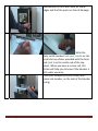
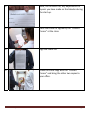
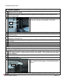
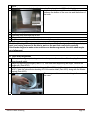
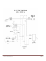
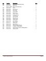
1
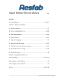
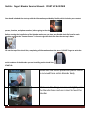
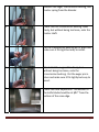
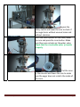
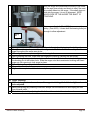
Start Up & Troubleshooting Manual
Resfab Equipment Inc.
725 Rossiter
725 Rossiter
St‐Jean‐Sur‐Richelieu
1‐450‐359‐0800
Website: resfab.com
Yogurt Blender Service Manual
Page
SECTION 1:
Start Up and Repair …………………………………….……………………………………..… 3 thru 11
SECTION 2: TROUBLE SHOOTING
#1: Elevator Alignment …………………………. ……………………………………...…............…12
#2 Elevator
#2:
El t Height
H i ht Adjustment
Adj t
t …………………… .………………………...…..…...….…12,
12 13
#3: Drive Shaft Alignment ………………………..………………………………..………….….13, 14
#4: Auger Vibrating ………………………………………...………………………………..…….…14,15
g Not Engaging
g g g ………………………….. …………..……………………………...…...…15
#5: Auger
#6: Auger Does Not Disengage ………………………….. ………………….………….…..…15, 16
#7: Grinding Noise From Aluminum Housing ………………………….………………...16, 17
#8: Rinse Water Valve is Leaking ……………………………………………………………….17, 18
#9: End Product Issues: …………………………………………. ………………………………….…..18
SECTION 3: DRAWINGS & PARTS LIST
Internal Drawings ………………………………………………………………………………..19 Thru 23
Electric Diagram 120V, 50/60 Hz ……………………………………………………………………. 24
Electric Diagram 220 V, 50/60 Hz …………………………………………………………………….25
Part List ……………………………………………………………………………………………….26 thru 28
2
Resfab : Yogurt Blender Service Manual : START UP & REPAIR You should schedule the start up with the information provided by Resfab; which includes your contact person, location, and phone number, before going to the site. Before starting the installation of the blender make sure you have one Resfab check list form for each machine and that the “Contact Person” is there to sign the check list after the start up is done. Fill out the top of the check lists, completing all information about the store. DO NOT forget to write the serial numbers of the blenders you are installing on the check lists. START UP: 1 2 Make sure the entire protective plastic shield is removed from entire blender body Make sure the 4 legs are screwed tightly onto the blender base and use a level to level the blender Resfab Start Up Page 3 3
Make sure blender is turned off and unplugged from the outlet. Remove the tray. 4
5
6
Resfab Start Up Remove the front panel, the mobile guard pins and mobile guards, the top and lower shield, the top cover and unscrew the cabinet and remove it. Screw (turning counter clockwise) the extrusion matrix onto the cone to make sure that it screws freely Page 4 7
Remove the auger, transmission bushing, and master spring from the blender. 8
Check that the transmission bushing slides freely, but without being too loose, onto the master shaft. 9
Put the transmission bushing pin in place and make sure it fits tight but easy to install. 10
Check that the auger slides freely, but
without being too loose, onto the transmission bushing. Put the auger pin in place and make sure it fits tightly but easy to insert. 11
Check the knife adjustment. The bottom of the knife blade should be at 5/32’’ from the bottom of the cone edge. Resfab Start Up Page 5 12
Check that the belt is well adjusted and not too tight. 13
Check that the elevator will move up and down without any resistance. 14
Check visually the aluminum base to make sure there are no cracks. 16
Check the stainless steel lever on each side and make sure there are no loose bolts, screws or nuts. Resfab Start Up Page 6 17
Check if the arm is screwed tightly and does not move inside the arm holder. 18
Put back the lower shield, the top shield, the mobile guard and the tray. 19
Plug blender into the outlet and turn unit on. Resfab Start Up Page 7 20
21
Bypass the safety switch and lower the arm to check if the auger turns without unusual noise and without vibration. With the rinse cylinder on the cone, lower the arm and press the rinse button. Make sure there are no leaks on the water valve. Check that the rise double water jet works properly. 22
Put the cone in the elevator and lower the arm to make sure the auger does not scratch the inside of the cone. Resfab Start Up Page 8 23
Reassemble the unit and check for sharp edges and that the parts are free of damage. 24
25
Resfab Start Up Write the date, serial numbers and your initials on the small start up sticker provided with the form and stick it on the inside end of the top panel. When you have a service call, this sticker will help you to know if the blender is still under warranty. Place your company service sticker, with name and number, on the side of the blender casing. Page 9 26
Note, on the check list, any adjustments or repairs you have made on the blender during the start up. 27
Have the check list signed by the “Contact
Person” at the store. 28
Sign the check list. 29
Leave the store copy with the “Contact
Person” and bring the other two copies to your office. Resfab Start Up Page 10 30
Resfab Start Up Fax or e‐mail the factory copy to the factory and mail the original, keeping the copy for your records. FAX: 352‐728‐1904 EMAIL: [email protected] Mail the invoice for the Start Up, along with the original Post Verification Inspection Start Up form to: Resfab Equipment 8645 Treasure Island Road Leesburg, FL 34788 Page 11 TROUBLE SHOOTING:
#1: Elevator Alignment:
If there is resistance when operating the arm, the aluminum elevator may be out of
1 alignment on the shafts.
Before performing any cleaning or service, always turn the machine off and unplug the unit
2 from the wall outlet.
3 Remove the front cover.
This is easily corrected by readjusting the turnbuckle
at the front, left side of the blender. Part #238
Nut
#238
4
5 Remove the mobile guard. Loosen the top nut over the aluminum shaft.
Readjust turnbuckle by turning it left or right, until aluminum elevator slides smoothly up and
6 down the shafts.
7 Retighten turnbuckle nuts.
Check alignment by raising and lowering the arm. Elevator should slide smoothly up and down
8 the shafts.
9 Reinstall mobile guards and front cover.
10 Plug unit back into outlet.
11 Alignment is complete and blender is ready for operation.
#2: Elevator Height Adjustment:
If the blender begins to make a noise; or if the cone begins to develop grooves; or if the
knife begins to wear; or the product is stuck in the matrix: The elevator stop pins need
1 to be adjusted.
Before performing any cleaning or service, always turn the machine off and unplug the unit
2 from the wall outlet.
3 Remove the front cover.
Two stop pins are located on each side of the top
front, near the mobile guards. Part #228 Adjustment
Screw.
#228
4
5 Pull arm down to raise cone and check the clearance between the cone and the bottom of the
Resfab Trouble Shooting Page 12 knife.
6 If readjustment is needed, begin by loosening the stop pin nuts #228 on both sides.
Adjust both side pins until there is a 5/32” clearance
between the bottom of the cone rim and the bottom of
the knife.
7
8
9
10
11
Retighten stop pin nuts #228 and recheck the clearance.
Reinstall front cover and top of unit.
Plug unit back into outlet.
Adjustment is complete and the blender is ready for operation.
All of the following different repairs have to be done with the front panel, mobile guard, top
panel, and casing removed to be able to work on the part that needs to be repaired.
If the blender begins to make noise and the cone becomes grooved, the drive shaft maybe
out of alignment.
#3: Drive Shaft Alignment:
Before performing any cleaning or service, always turn the machine off and unplug the unit
1 from the wall outlet.
Begin by removing the auger (Part #111) With one hand supporting the auger, remove the
2 auger pin. (Part #110)
Utilizing the auger pin, push the bushing pin (Part #106) out of the transmission bushing (Part
#107); slide the transmission bushing off of the master shaft (Part #103) along with the master
3 spring (Part #105).
Place auger and transmission bushing in the center of
the cone.
4
Resfab Trouble Shooting Page 13 With the auger and transmission bushing in the cone;
pull the arm down slowly and check to see if the main
drive shaft slides into the auger. If the shaft does not
slide into the auger, it is out of alignment. NOTE
WHICH SIDE OF THE AUGER THE SHAFT IS
TOUCHING.
5
First remove the belt, (Part #229) then remove the
pulley, (Part #102). Loosen both the bearing bolts just
enough to allow adjustment.
Bearing
Bolt
6
7 Looking into cone, check the alignment of the shaft and adjust by tapping the shaft gently.
Slowly lower the arm down to recheck the alignment. Shaft should slide smoothly into the
8 auger throughout the entire arm stroke.
9 When alignment is complete, retighten the baring bolts.
10 After tightening the bolts, make one final alignment check by lowering the arm slowly.
Place the large spring onto the main drive shaft and reinstall the transmission bushing, placing
the bushing pin in the bottom hole. Slide the auger onto the transmission bushing and insert
11 auger pin into opening to lock auger in place.
12 Reinstall the pulley and put the belt back on.
13 Plug unit back into outlet.
14 Alignment is complete and blender is ready for operation.
#4: Auger Vibrating:
1 If blender begins to make a noise, or the auger is shaking, the belt is too tight and needs
to be adjusted.
2 Before performing any cleaning or service, always turn the machine off and unplug the unit
from the wall outlet.
3 The belt is adjusted by adjusting the 4 bolts from the motor to the main channel.
Resfab Trouble Shooting Page 14 4
Use a ½” wrench to untighten the lower bolts from the
motor to the main channel. If you need to loosen the
belt more, tighten the upper bolts slightly.
Upper
Bolt
Lower
Bolt
5 Plug unit back into outlet.
6 Alignment is complete and blender is ready for operation.
#5: Auger not engaging:
1 If the machine does not start when lowering the arm: The back flapper (Part #250) is to
loose and cannot activate the micro switch.
2 Remove the front panel, top and cabinet.
3
Make sure the power switch is on.
4
Using your finger move the back flapper and check if it
is loose.
If it is loose, use a 9/16'' wrench and tighten the bolt of
the flapper. You should tighten with approximately 45
pound of torque.
5 Replace cabinet, top and front panel.
6 Plug unit back into outlet.
7 Service is complete and blender is ready for operation.
#6: Auger does not disengage:
1 If the auger does not stop turning, that means the micro switch (Part #241) is defective
and needs to be replaced.
Resfab Trouble Shooting Page 15 2 Remove the front panel, top and cabinet.
3 Make sure the power switch is ''OFF''.
4
First, with a screwdriver you will unscrew the 2 wires
on the micro switch and remove them from the micro
switch. Then use a 9/16'' wrench to remove the flat
nut at the back of the micro switch. Remove the
defective micro switch. Take the new micro switch
and screw it back in place and screw the electric wire
back into the switch.
5 Replace cabinet, top and front panel.
6 Plug unit back into outlet.
7 Service is complete and blender is ready for operation.
#7: Grinding Noise from Aluminum Housing:
1 If a grinding noise is coming from the aluminum housing over the auger, the bearing is
worn and the housing assembly glides need to be replaced.
2 Before performing any cleaning or service, always turn the machine off and unplug the unit
from the wall outlet.
3 Remove the front, top, cabinet cover, front plate and the belt guard.
4 Remove the auger (Part #111), transmission bushing (Part #107) and the waster spring (Part
#105).
5 Remove the belt (Part #229) to free the pulley
6 Loosen the setscrew of the pulley and remove the pulley (Part#102).
7
Loosen the 2 setscrews on the bearing (Part #104)
Bearing
and finally, by using a 5/16” allen key, unscrew the 2
Bolt
bolts on each side of the flange bearing (Part #104)
Bearing
until the housing is free. You may need a rubber
Bearing
Set Screw
hammer to hit the top of the master shaft if the
housing is stuck on the top plate.
8
9
Remove the housing; remove the 2 o’rings on the flat
side of the housing.
Place the two o’rings on the new housing.
Housing
Assembly
10 Slide the new housing shaft in the top plate hole, then with the allen key screw back the 2 bolts.
Resfab Trouble Shooting Page 16 11
12
13
14
15
16
Before tightening the bolts, align the shaft with the
auger and transmission bushing in the cone. Screw
the bolts very tightly and screw the 2 setscrews.
Put the pulley back into place and tighten the pulley setscrews.
Put the belt back on.
Replace cabinet, top and front panel.
Plug unit back into outlet.
Service is complete and blender is ready for operation.
#8: Rinse water valve is leaking.
1 If the rinse water valve is leaking…
2 Before performing any cleaning or service, always turn the machine off and unplug the unit
from the wall outlet.
3 Remove the plastic hose from the back nylon fitting (Part #312). You may need a screwdriver
to unscrew the collar or a cutter if the factory secured the tube and the fitting with an oeteker
clamp.
4 Using an 11/16" wrench, remove the nylon fitting (Part #312).
5 With a screw driver or a knife, remove the silver cap on the valve button (Part #301).
6
Use two screw drivers, one in the front screw and one
in the back inside screw of the valve and unscrew until
the valve piston (Part #309) can be removed.
Resfab Trouble Shooting Page 17 7
Change the 4 o’rings on the valve piston. The big
o'ring needs to be slightly tight between the washer
and the end of the piston.
Valve
Piston
Screw
Washer
Big O’Ring
Small
O’Ring
8 Slide the spring on the valve piston and re-insert the valve piston in the valve body. Using the
two screw drivers to screw the piston in place.
9 Screw back the nylon fitting.
10 Re-connect the plastic tubing.
11 Re-install the silver cap in the valve button.
12 Plug unit back into outlet.
13 Service is complete and blender is ready for operation.
#9: End Product Issues:
1- If the product is coming out like whipped cream it’s because the product is too soft or too
hard.
2- If the product comes out like a round tube it’s because the product is too hard.
The optimal product temperature is minus 5° F or minus 17° C. That is the product
temperature not the freezer ambient temperature. Check regularly and with a sanitized
probe. Check the internal temperature of the product in the freezer.
Resfab Trouble Shooting Page 18 Resfab Trouble Shooting Page 19 Resfab Trouble Shooting Page 20 Resfab Trouble Shooting Page 21 Resfab Trouble Shooting Page 22 Resfab Trouble Shooting Page 23 Resfab Trouble Shooting Page 24 Resfab Trouble Shooting Page 25 PART LIST
No.
101
102
103
104
105
106
107
108
109
110
111
112
113
114
115
116
117
118
119
120
201
202
203
204
205
206
207
208
209
210
211
212
213
214
215
216
217
Part No.
R4-14-101
R4-14-102
R4-14-103
R4-14-104
R4-14-105
R4-14-106
R4-14-107
R4-14-108
R4-14-109
R4-14-110
R4-14-111
R4-14-112
R4-14-113
R4-14-114
R4-14-115
R4-14-116
R4-14-117
R4-14-118
R4-14-119
R4-41-120
R4-14-201
R4-14-202
R4-14-203A
R4-14-204
R4-14-205
R4-14-206
R4-14-207
R4-14-208
R4-14-209
R4-14-210E
R4-14-211
R4-14-212
R4-14-213
R4-14-214
R4-14-215
R4-14-216
R4-14-217
Resfab Trouble Shooting Description
Driven pulley key
Driven pulley
Master shaft
Flange pillow block
Master spring
Bushing pin
Transmission bushing
Knife holder stem
Knife spring
Auger pin
Auger
Knife
Dismounting tool
Bearing housing
Ball bearing
Great snap ring
Small snap ring
O-ring
Spacer bushing
Rubber seal
Base
Elevator
Vertical guides for R4-14-243
Main power switch
Power switch plate
Junction box
Spring pins
Opposite major lever
Hub pressure screw
Lever ergonomic
Lever pressure screw
Lever holder
Casing
Cover
Front panel
Acrylic plate
Electric rinse button
Qty.
1
1
1
1
1
1
1
1
1
1
1
1
1
1
1
1
1
2
1
1
1
1
1
1
1
1
1
1
1
1
1
1
1
1
1
1
1
Page 26 No.
218
219
220
221
222
225
226
227
228
229
230
231
232
232
233
234
235
236
237
238
239
240
241
243
244
245
246
247
248
249
250
251
252
253
254
255
256
257
258
259
260
Part No.
R4-14-218
R4-14-219
R4-14-220
R4-14-221
R4-14-222
R4-14-225
R4-14-226
R4-14-227
R4-14-228
R4-14-229
R4-14-230
R4-14-231
R4-14-232
R4-14—232S
R4-14-233
R4-14-234
R4-14-235
R4-14-236
R4-14-237
R4-14-238
R4-14-239
R4-14-240
R4-14-241
R4-14-243
R4-14-244
R4-14-245
R4-14-246
R4-14-247
R4-14-248
R4-14-249
R4-14-250
R4-14-251
R4-14-252
R4-14-253
R4-14-254
R4-14-255
R4-14-256
R4-14-257
R4-14-258
R4-14-259
R4-14-260
Resfab Trouble Shooting Description
Top shield
Lower shield
Belt guard
Rinse cylinder
Cone
Mobile guard pin
Mobile guard
Mobile guard guide
Adjustment screw
Belt
Top front plate
Driver pulley
Tray « Deep collar »
Tray « Sliding matrix »
Main pivot
Secondary pivot
Electric water valve
Motor (110,220 v – 50-60 Hz)
Power cord
Turnbuckle
Top plate
Main column
Micro-swtich
Linear bearing (teflon) / R4-14-203A
Vertical lever support
Driver pulley key
Major lever
Angular brace
Vertical lever
Horizontal brace
Sliding lever
Micro-switch support
Bulkhead connector
Fitting and nut
Switch wire
Stiffening angle
Nylon tube
Nylon elbow
Adjustable leg
Nylon « T »
Assembled valve
Qty.
1
1
1
1
1
2
2
2
2
1
1
1
1
1
1
1
1
1
1
1
1
1
3
2
1
1
2
2
2
1
1
1
1
1
4
2 m.
3
4
1
1
Page 27 No.
261
262
263
264
301
302
303
304
305
306
307
308
309
310
311
312
319
320
321
332
Part No.
R4-14-261
R4-14-262
R4-14—262G
R4-14-263
R4-14-264
R4-14-301
R4-14-302
R4-14-303
R4-14-304
R4-14-305
R4-14-306
R4-14-307
R4-14-308
R4-14-309
R4-14-310
R4-14-311
R4-14-312
R4-14-319
R4-14-320
R4-14-321
R4-14-332
Resfab Trouble Shooting Description
Assembled bearing housing
Matrix nut
Matrix with slide Ass’y
Knob
Nylon fitting
Front plug
Front screw
Push button
Return spring
Cylindrical nut
Valve husing
Small O-ring
Great O-ring
Valve piston
Stop washer
Rear screw
Nylon fitting
Relay (model 920 only)
O-ring for Sliding Matrix
Red blocking screw for Sliding Matrix
Safety switch
Qty.
1
1
1
1
2
1
1
1
1
1
1
3
1
1
1
1
1
1
2
1
1
Page 28