1
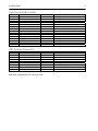
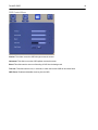
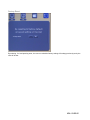
DURAVIS 3400
User Manual
MNL-0545-01 revB
REF ECO-1119
Effective: 27-APR-07
Disclaimer
Although the information contained herein has been carefully verified, Parvus Corporation assumes no
responsibility for errors that might appear in this document, or for damage to property or persons resulting from
improper use of this manual or related software. Parvus reserves the right to change the contents and form of
this document, as well as the features and specifications of its products at any time without notice. The
information in this publication does not represent a commitment on the part of Parvus. This document contains
proprietary information that is protected by copyright. All rights are reserved. No part of this document may be
photocopied, reproduced, or translated into another language without the prior written consent of Parvus.
Parvus Corporation
3222 S. Washington St.
Salt Lake City, Utah, USA 84115
Phone: +1 (801) 483-1533
Toll-Free:
+1 (800) 483-3152
Main:
+1 (801) 483-1533
Fax:
+1 (801) 483-1523
Email:
Sales:
[email protected]
Support:
[email protected]
Web-site:
http://www.parvus.com
Send us your comments and feedback: [email protected]
Parvus is the U.S. arm of the Eurotech Group (www.eurotech.com), a global family of technology companies
focused on innovative embedded and high performance computing solutions.
Trademarks
Trademarks and registered trademarks appearing in this document are the property of their respective owners.
MNL-0545B-01
DuraVIS-3400
3
IMPORTANT INFORMATION TO THE USER
Before proceeding further, please carefully read the following paragraphs:
Safety Notices and warnings
FCC information and compliance
This device has been designed to comply within the limits of a Class B digital device pursuant to Part 15 of the
FCC Rules. These limits are designed to provide reasonable protection against harmful interference. The device
generates, uses, and can radiate radio frequency energy and, if not installed and used in accordance with the
instructions, may cause harmful interference to radio communications or to devices that are not appropriately
shielded.
Parvus is not responsible for any radio or device, which may be affected by harmful interference. Appropriate
shielding of susceptible devices is not the responsibility of Parvus. Further, Parvus is not responsible for
unauthorized modifications of Parvus equipment including the substitution or attachment of cables and/or other
unauthorized equipment. If electrical interference is harmfully affecting a device, it is the responsibility of the user
to correct this interference.
In order to minimize the affects of electrical interference, use only shielded data cables with the system.
In accordance with FCC 15.21, changes or modifications not expressly approved by the party responsible for
compliance could void the user’s authority to operate the equipment.
Emissions information for Canada
This Class B digital apparatus complies with Canadian ICES-003. Cet appareil numérique de la classe B est
conforme à la norme NMB-003 du Canada.
CE Marking
This equipment complies with the requirements for CE marking when used in a residential,
commercial, vehicular or light industrial environment.
RAEE
The information below is issued in compliance with the regulations as set out by the 2002/96/CE directive,
subsequently superseded by 2003/108/CE, and refers electrical and electronic equipment and the management
of their waste (WEEE). When disposing of a device, including all of its components, subassemblies and
materials that are an integral part of the product, you should take the WEEE directive into consideration.
This symbol has been attached to the equipment or, in the case that this is not possible, on the
packaging, instruction literature and/or the guarantee sheet. By using this symbol it states that the
device has been marketed after August 13th 2005, and implies that you must separate all of its
components when possible, and dispose of them in accordance with local waste disposal legislations.
¾
Because of the substances present in the equipment, an improper use or disposal of the refuse can cause
damage to human health and to the environment.
¾
With reference to RAEE, it is compulsory to not dispose of the equipment with normal urban refuse,
arrangements should be instigated for separate collection and disposal.
¾
For more detailed information about recycling of RAEE, please contact your local waste
collection body.
¾
In case of illicit disposal, sanctions will be levied on transgressors.
RoHS
This device, including all it components, subassemblies and the consumable materials that are an integral
part of the product, has been manufactured in compliance with the European directive 2002/95/EC known as
the RoHS directive (Restrictions on the use of certain Hazardous Substances), this directive targets the
reduction of certain hazardous substances previously used in electrical and electronic equipment (EEE).
Anti-static precautions
Always use appropriate antistatic precautions when handing any board. This is to avoid damage
caused by ESD (Electro Static Discharge).
MNL-0545B-01
DuraVIS-3400
5
Conventions
The following table lists the conventions that are used throughout this manual.
Icon
Notice Type
Information note
Warning
Description
Important features or instructions
Information to alert you to potential
damage to a program, system or device
or potential personal injury
The “Mode” of the register:
R/W Read and write register.
RO Read only register.
W
Meaning of the register when written.
R
Meaning of the register when read.
Hexadecimal numbers:
Hexadecimal numbers are indicated with an “h” suffix (for example: 11Ch).
Other:
NC
Not internally connected
Reserved
Use reserved to Factory
Table of Contents
Disclaimer .............................................................................................................................................................2
Trademarks ...........................................................................................................................................................2
IMPORTANT INFORMATION TO THE USER .....................................................................................................3
Safety Notices and warnings..........................................................................................................................3
RAEE..............................................................................................................................................................4
RoHS ..............................................................................................................................................................4
Anti-static precautions...........................................................................................................................................4
Conventions ..........................................................................................................................................................5
Table of Contents ...................................................................................................................................................6
Chapter 1
Product Overview .............................................................................................................................8
Product Definition..................................................................................................................................................9
Chapter 2
Connector Descriptions ................................................................................................................ 10
DB9 Male (Serial)............................................................................................................................................... 10
High Density DB15 (VGA).................................................................................................................................. 11
DB9 Female (Power/Int)..................................................................................................................................... 11
Chapter 3
Interconnection/Cable Description .............................................................................................. 12
Chapter 4
Touch Screen Driver...................................................................................................................... 13
Installing the Driver ............................................................................................................................................ 14
Calibrating the Display ....................................................................................................................................... 14
Chapter 5
User Controls ................................................................................................................................. 15
Operating System Display buttons..................................................................................................................... 15
Chapter 6
On Screen Menu............................................................................................................................. 16
Window Structure............................................................................................................................................... 18
OSD Start Menu .......................................................................................................................................... 18
Main menu................................................................................................................................................... 18
Descriptions of Display Functions ............................................................................................................... 19
Image Function VGA mode ......................................................................................................................... 20
Position Functions VGA Mode .................................................................................................................... 21
MNL-0545B-01
DuraVIS-3400
7
Descriptions of Color Functions .................................................................................................................. 22
Descriptions of PIP-Control Functions ........................................................................................................ 22
OSD Control Menu ...................................................................................................................................... 23
Factory Reset .............................................................................................................................................. 24
Chapter 7
Troubleshooting............................................................................................................................. 25
Technical/Sales Assistance ............................................................................................................................... 25
Returning For Service ........................................................................................................................................ 25
LIMITED WARRANTY ....................................................................................................................................... 26
Chapter 1
Product Overview
The DuraVIS 3400 is a rugged 10.4" resistive touch screen flat panel display optimized for panel-mount
installations in ships, aircraft, and ground vehicles. Its 400 Nit SVGA (800x600) resolution color Liquid Crystal
Display is built into a robust mechanical design with internal shock and vibration isolation, hardened aluminum
housing, and integrated gaskets for water and EMI resistance.
MNL-0545B-01
DuraVIS-3400
9
Product Definition
Panel Type:
10.39" Diagonal TFT-LCD with CCFL Backlight
Touch screen:
Resistive Film Touch screen Overlay and RS-232 Controller
Viewable Area:
211.2mm (W) x 158.4mm (H)
Resolution:
SVGA (800x600 pixels)
Contrast Ratio:
500:1 (typical)
Number of Colors:
260,000
Response Time:
30ms (typical) black to white; 10ms (typical) white to black
Luminance:
400 cd/m² (nit) typical
Video Input:
Standard VGA Video Input, 800x600
Viewing Angle:
160 degree conical (-70~70° (H), -60~50° (V))
Power Input:
Input: 9-36VDC (12-28V nominal)
Vibe Isolation:
Internal Silastic Boot for Shock & Vibration Isolation
Material/Finish:
6061T6 Aluminum, Black Anodized Hardened Finish
Surface Treatments:
Anti-Glare and ITO Hard Coating 3H
Operating Temp:
-20°C to +60°C (-4°F to +140°F)
Storage Temp:
Weight: Approx.
-20°C to +80°C (-4°F to +176°F)
7.5 Lbs (3.4 Kg)
Options:
External protective boot for added handling protection in mobile applications.
External brightness control unit on the power cable to adjust brightness
externally.
Chapter 2
Connector Descriptions
The DuraVIS 3400 is equipped with two DB9 connectors and one DB15 connector. The male DB9 port is used
as an RS-232 interface for touch screen control. The VGA connector serves as the video input to the display and
the female DB9 connector is used for power input.
Front View
Rear View
DB9 Male (Serial)
Pin Number
1
2
3
4
5
6
7
8
9
Signal Name
N/C
Rx
Tx
N/C
GND
N/C
N/C
N/C
N/C
Input / Output
Comment
Input
Input
Receive
Transmit
Input
Ground
MNL-0545B-01
DuraVIS-3400
11
High Density DB15 (VGA)
Pin Number
1
2
3
4
5
6
7
8
9
10
11
12
13
14
15
Signal Name
Red
Green
Blue
N/C
Ground
Ground
Ground
Ground
VGA_Vcc
Ground
N/C
VGA_SDA
HSYNC
VSYNC
VGA_SCL
Input / Output
Input
Input
Input
Input
Input
Input
Input
Input
Input
Comment
VGA Signal
VGA Signal
VGA Signal
VGA Signal
Input
Input
Input
Input
VGA Signal
VGA Signal
VGA Signal
VGA Signal
Input / Output
Input
Input
Input
Input
Input
Input
Input
Input
Input
Comments
Incoming Power Interface Tied to Pin 6
Intensity Control
Intensity Control
DB9 Female (Power/Int)
Pin Number
1
2
3
4
5
6
7
8
9
Signal Name
Vin
Down
Up
Analog
GND_In
Vin
GND
GND
GND_In
Note: Input Voltage Range is 9 Volts to 36 Volts.
Incoming Power Interface
Incoming Power Interface. Tied to Pin 1
Intensity Control
Intensity Control
Incoming Power Interface
Chapter 3
Interconnection/Cable Description
The following cables are necessary to connect to the DuraVIS-3400:
•
Standard Male to Male VGA/SVGA cable.
•
Power cable with a DB9 Male Connector: The input voltage is applied to pin 1 or 6 (The two pins are
connected in the unit), and the ground input is applied to pin 5 or 9 (The two pins are connected in the
unit). The Ground signals of the DB9 (pins 7 or 8) are connected to the common of the Molex connector
(pin 1) of the external intensity control. Pins 3 and 2 of the DB9 connector are connected to pins 3 and 2
of the brightness control, respectively.
•
Serial Female to Female cable: In order to have the touch screen communicate with a computer, it is
necessary to use a straight-through, serial Female to Female cable. Pin 5 of both connectors are
connected together, pin 2 is connected to pin 2, and pin 3 is connected to pin 3. A null modem cable will
also work if your system has auto crossover.
MNL-0545B-01
DuraVIS-3400
Chapter 4
13
Touch Screen Driver
Parvus provides a Windows XP driver and calibration program for the DuraVIS 3400. This chapter describes
how to install this driver and run the calibration program.
Touch screen drivers for DOS and Linux are available upon request.
Installing the Driver
Follow these steps to install the touch screen driver:
•
Install SFT-0369X-01 by running setup.exe.
•
On the welcome screen, click next.
•
Read and accept the EULA, and click next.
•
On the next screen select “12 or10 Bit Controller” for controller type and “Serial (RS/232)” for the
controller interface then try to auto-detect. The touch screen controller should be detected.
•
On the next screen, ensure that the correct COM port for your serial port is selected and that the baud
rate is 9600. Make sure that the capacitive controller is not checked. Click next and finish.
•
Cycle the power on your system before you start using the touch screen.
•
After completing the preceding steps, a new program labeled “TPI Touch Screen Control Panel” should
be in your program directory. This program is used to calibrate and change settings on the touch
screen.
Calibrating the Display
To calibrate or change settings on the DuraVIS3400 follow these steps:
•
After installing the driver, open the “TPI Touch Screen Control Panel” program
•
Select the Calibration tab, and click Configure.
•
This will bring up a menu letting you choose the precision of the calibration. Select the number of touch
points and click OK.
•
Touch and hold where the bulls-eye appears until it says to release it.
•
Continue until the touch screen is fully calibrated, then click Accept.
•
To enable/disable touch sound, click Touch Settings and select/unselect touch sound.
•
Click exit to finish the calibration.
MNL-0545B-01
DuraVIS-3400
Chapter 5
15
User Controls
Operating System Display buttons
On the back side of the touch screen, under the OSD cover plate, there are several buttons to interface with the
display. The functions of these buttons are as follows:
Button
Name
Function
Button 1
Right/increase:
This button is used to scroll right in the OSD menu, and also increases the
value once an attribute is selected.
Button 2
Menu/Exit button
This button is used to enter the OSD menu mode, and is also used to exit
an attribute or exit the OSD menu.
Button 3
Left/Decrease
This button is used to scroll left in the OSD menu. It also decreases the
value once an attribute is selected.
Button 4
Select
This button is used to select an attribute that you would like to change.
Button 5
Increase
Brightness
This button increases the intensity of the backlight
Button 6
Decrease
Brightness
This button decreases the intensity of the backlight.
The brightness can be adjusted using the OSD buttons on the back of the unit or using the optional external
switches. It should be noted that the brightness control on the OSD menu is not interfaced with the brightness
up/down of the unit. This is an option that is not implemented in this design.
Chapter 6
On Screen Menu
All the display functions, except for backlight intensity, can be controlled and adjusted using an On-ScreenMenu. This chapter explains all functions and their factory settings (valid for Firmware v2.13 and above).
MNL-0545B-01
DuraVIS-3400
17
Window Structure
OSD Start Menu
The main menu consists of the main input symbol, the PIP symbol, the OSD setting symbol, and factory autoreset symbol. By selecting one of these symbols and pressing the Enter key, the sub-menus will be displayed.
Main menu
This menu is used to control the functions associated with the main input of choice. Main display consists of the
Display, Image, Position, Color, PIP Control, and Input Select sub menus.
MNL-0545B-01
DuraVIS-3400
19
Descriptions of Display Functions
Brightness: The brightness control on the OSD menu is not interfaced with the brightness up/down of the unit.
This is an option that is not implemented in this design. The backlight intensity can be controlled through the
OSD buttons on the back of the display or through the external switches (optional).
Contrast: Allows Contrast adjustment in the Y domain. The modification affects all color channels and all input
types and is a direct multiplication of the Y data after YUV black level adjustment.
Hue: Allows Hue adjustment in the UV domain. The modification affects all color channels and all input types.
Saturation: Allows Saturation adjustment in the UV domain. The modification affects all color channels and all
input types.
Flesh Tone: Allows adjustment of the gain of the V component in the UV domain. The modification affects all
color channels and all input types. The application of Flesh Tone is to correct the skin color to provide a natural
appearance of skin. This function has predefined values. Off/weak/soft/strong flesh-tone values can be selected.
Black Level: Allows Black Level adjustment in the Y domain. The modification affects all color channels and all
input types and is a subtracted from the Y data prior to YUV contrast adjustment.
Image Function VGA mode
Scaling: User can choose between 1:1, Fill, Aspect and Panorama modes.
Auto Adjust: Allows the performing of automatic setting adjustment. The display will change the settings for
optimum image quality.
Phase: This function is a slider to adjust the sampling phase of the analog interface. For optimum image quality,
input pixels should be sampled at the ideal sampling points as shown below:
Clock: This function is a slider to adjust the sample clock of the analog interface. This is helpful for improving the
image quality for non-standard display modes.
MNL-0545B-01
DuraVIS-3400
Position Functions VGA Mode
Zoom: Selection of image zooming in and out.
Zoom Horizontal Pan: Allows moving the zoomed image left and right.
Zoom Vertical Pan: Allows moving the zoomed image up and down.
Vertical: This slider moves the image up and down.
Horizontal: This slider moves the image left and right.
21
Descriptions of Color Functions
sRGB: Enables/Disables the standard RGB color space.
Gamma Correction: Turns gamma correction off, or sets its value to one of two predefined values.
Color Temperature: User can set the color temperature to either self defined values, or to predefined values of
6500K or 9300K.
Red/Green/Blue: These three sliders are used to decrease/increase intensities of each color.
Descriptions of PIP-Control Functions
This function is not implemented in the DuraVIS-3400 Series 10.4” displays
MNL-0545B-01
DuraVIS-3400
OSD Control Menu
Vertical: This slider moves the OSD left/right across the screen.
Horizontal: This slider moves the OSD up/down across the screen.
Blend: This slider sets the amount of blending of OSD into the background.
Time out: This slider sets the time, in seconds, in which the inactive OSD will shut itself down.
OSD Zoom: Enables and disables zooming into the OSD.
23
Factory Reset
By selecting ‘Yes’ and pressing enter, the user can reload the factory settings. All settings previously set by the
user will be lost.
MNL-0545B-01
DuraVIS-3400
25
Chapter 7 Troubleshooting
Technical/Sales Assistance
If you have a technical question or if you cannot isolate a problem with your PC/104 system, please call or e-mail
the Parvus Technical Support:
¾
Email: [email protected]
¾
Phone: +1 (801) 483-1533
¾
Fax: +1 (801) 493-1523
If you have a sales-related question, please contact your local Sales Representative.
Returning For Service
Before returning any Parvus product, you must contact Parvus to obtain a Returned Material Authorization
(RMA) number.
Note. You must have the RMA number in order to return any product for any reason!
Pack the module in an anti-static material and ship it in a sturdy cardboard box with enough packing material to
adequately cushion it.
Warning! Any product returned to Parvus improperly packed will immediately void the warranty for
that particular product!
For more information about this or other products in the Parvus line of embedded systems solutions, call (801)
483-1533 from 8:00AM to 5:00PM Mountain Time, E-mail us at [email protected] or visit our web-site at:
http://www.parvus.com
LIMITED WARRANTY
Parvus Corporation warrants this product to be free of defects in materials and workmanship, and that the
product meets or exceeds the current specifications published by Parvus. This Warranty is valid for a period of
one (1) year from the date of purchase. Parvus reserves the right to repair or replace any Warranted products at
its sole discretion. Any product returned to Parvus for repair or replacement under the provisions of this warranty
must be accompanied by a valid Return Material Authorization (RMA) number issued by the Parvus Customer
Service Department.
Parvus Corporation makes no warranty not expressly set forth in this document. Parvus disclaims and excludes
all implied warranties of merchantability and fitness for a particular purpose. The aggregate liability of Parvus
arising from or relating to (regardless of the form of action or claim) is limited to the total of all payments made to
purchase the product. Parvus shall not in any case be liable for any special, incidental, consequential, indirect or
punitive damages, even if Parvus has been advised of the possibility of such damages. Parvus is not
responsible for lost profits or revenue, loss of the use of software, loss of data, costs of recreating lost data, or
the cost of any substitute equipment or program.
This Warranty shall be governed by the laws of the United States of America and the State of Utah, and any
claim brought under this Warranty may only be brought in state or federal court located in Salt Lake County,
State of Utah, and purchaser hereby consents to personal jurisdiction in such courts.
For further information contact:
Parvus® Corporation
3222 S. Washington St.
Salt Lake City, Utah, USA 84115
(801) 483-1533, FAX (801) 483-1523
Web-site: http://www.parvus.com
MNL-0545B-01