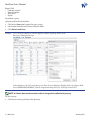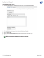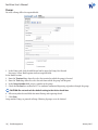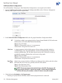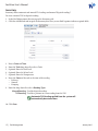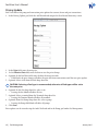
1
Fuel View
User’s Manual
W4 Fuel View Features
W4 Fuel View’s many features help simplify the management of fleet resources.
Improved Ease of Use
• Centralized, configurable reports covering one or more specific departments, one or more business units, or
the entire customer fleet.
• Online, context appropriate help, down to the field level.
• User customizable “views” within the application.
• Dashboard view of Key Performance Indicators.
Security
• Expanded capability to define users based on roles and privileges.
• Secure logins and configurable access to system.
• Enhanced audit trail and security features allow the system to track who did what and when at any time, for
any transaction or record change.
Improved Flexibility and Enhanced Reliability
• Online and backup stand-alone mode communications.
• Authorization and processing of transactions in both real-time and back-up modes.
• Supports multiple input devices: CANceiver Vehicle Information Transmitters (VIT™), magnetic and
proximity cards, key FOBs, and tags.
Fuel Tank Management
• Automated inventory management of liquid fuels through the interface with tank level sensing equipment or
manually through manual “dipstick method”.
• Site Status Reporting includes fuel reorder points and potential problems through the easy to use visual
status grid.
Simplified Operation and Maintenance
• Remote diagnostic and trouble-shooting.
Fuel View User’s Manual
Contents
1.Requirements...........................................................................................................................................................1
Hardware and Software Components....................................................................................................................................1
System Requirements...................................................................................................................................................................1
TCP Ports...........................................................................................................................................................................................2
Browser Support.............................................................................................................................................................................2
2. Basic Use....................................................................................................................................................................3
Logging In.........................................................................................................................................................................................3
Logging Off......................................................................................................................................................................................3
Directory............................................................................................................................................................................................4
Grids....................................................................................................................................................................................................5
Tool Bar..............................................................................................................................................................................................5
Query..................................................................................................................................................................................................5
Field Level Filters............................................................................................................................................................................7
Sort......................................................................................................................................................................................................7
Predefined Filters...........................................................................................................................................................................7
User-Defined Filters.......................................................................................................................................................................7
Toggle a Filter...............................................................................................................................................................................9
Clear Filter Criteria......................................................................................................................................................................9
Save a Filter...................................................................................................................................................................................9
Columns..........................................................................................................................................................................................10
Customize a Grid.......................................................................................................................................................................10
Add a Column............................................................................................................................................................................10
Remove a Column....................................................................................................................................................................11
Create a Group..........................................................................................................................................................................11
Export...........................................................................................................................................................................................12
Audit Trail........................................................................................................................................................................................13
Records............................................................................................................................................................................................13
Add Record.................................................................................................................................................................................13
View Record Details.................................................................................................................................................................14
Edit a Record..............................................................................................................................................................................14
Deactivate a Record.................................................................................................................................................................14
Re-activate a Record................................................................................................................................................................14
3.Dashboard.............................................................................................................................................................. 15
i | TOC January 2015
Fuel View User’s Manual
Directory..........................................................................................................................................................................................15
View Details....................................................................................................................................................................................16
Export...............................................................................................................................................................................................16
Export to PDF.............................................................................................................................................................................16
Export to Image........................................................................................................................................................................17
Transaction Analysis....................................................................................................................................................................18
Query............................................................................................................................................................................................19
4.Status....................................................................................................................................................................... 20
Tank and Pump Detail................................................................................................................................................................20
Tank Activity...............................................................................................................................................................................20
Alarms...........................................................................................................................................................................................20
Terminal Status.............................................................................................................................................................................21
Request Terminal Call.................................................................................................................................................................21
Tank Level Sensor Status...........................................................................................................................................................22
Tank Watch..................................................................................................................................................................................23
5. Asset Management............................................................................................................................................... 24
Departments..................................................................................................................................................................................24
Employees......................................................................................................................................................................................25
Change Employee Fueling Status ......................................................................................................................................26
Vehicles............................................................................................................................................................................................27
Vehicle Type...................................................................................................................................................................................30
Vehicle Emission Config.............................................................................................................................................................31
Site Cards........................................................................................................................................................................................32
6. Site Management.................................................................................................................................................. 33
Sites...................................................................................................................................................................................................34
Terminals.........................................................................................................................................................................................35
Tanks.................................................................................................................................................................................................37
Pumps..............................................................................................................................................................................................39
Manifolds........................................................................................................................................................................................40
Pump Chaining.............................................................................................................................................................................41
Terminal Alerts .............................................................................................................................................................................42
7. CANceiver Management...................................................................................................................................... 43
CANceiver Set Up.........................................................................................................................................................................43
Important Definitions.............................................................................................................................................................43
ii | TOC January 2015
Fuel View User’s Manual
CANceiver Events.........................................................................................................................................................................43
Create an Event Configuration............................................................................................................................................43
Edit a Configuration.................................................................................................................................................................46
Deactivate an Event Configuration....................................................................................................................................46
Reactivate an Event Configuration....................................................................................................................................46
Edit an Event Map....................................................................................................................................................................46
Delete a Event Map..................................................................................................................................................................46
CANceiver Logs.............................................................................................................................................................................46
Network Config.............................................................................................................................................................................47
GPIO..................................................................................................................................................................................................48
GPIO Vehicle Maps.......................................................................................................................................................................49
Configuration................................................................................................................................................................................49
Add Main Configuration........................................................................................................................................................50
For Vehicles.............................................................................................................................................................................50
For Departments...................................................................................................................................................................50
Add Network Configuration.................................................................................................................................................51
For Vehicles.............................................................................................................................................................................51
For Departments...................................................................................................................................................................51
Add Immediate Configuration............................................................................................................................................52
For Vehicles.............................................................................................................................................................................53
8. Transaction Management................................................................................................................................... 54
9. Fuel Management................................................................................................................................................. 56
Fuels..................................................................................................................................................................................................56
Inventory.........................................................................................................................................................................................57
Receipts...........................................................................................................................................................................................58
Tank Transfers................................................................................................................................................................................59
Adjustments...................................................................................................................................................................................60
Pump Totalizer...............................................................................................................................................................................61
Pricing Update..............................................................................................................................................................................62
View Historic Prices..................................................................................................................................................................63
10.Reporting................................................................................................................................................................ 64
Create Reports...............................................................................................................................................................................64
Reports.............................................................................................................................................................................................66
Alter Grid Reports........................................................................................................................................................................66
iii | TOC January 2015
Fuel View User’s Manual
Pivot Grids.......................................................................................................................................................................................67
Schedule an Auto Run Report.................................................................................................................................................68
11.Message Management......................................................................................................................................... 69
Message Management...............................................................................................................................................................69
Messages by Vehicle...................................................................................................................................................................70
Remove a Message..................................................................................................................................................................71
Discontinue a Message..........................................................................................................................................................71
Copy Messages to Another Vehicle....................................................................................................................................72
12.Security................................................................................................................................................................... 73
Users.................................................................................................................................................................................................73
Deactivate a User......................................................................................................................................................................74
Change a Password.....................................................................................................................................................................75
Appendix A................................................................................................................................................................... 76
PIDs ..................................................................................................................................................................................................76
Special PIDs....................................................................................................................................................................................77
Hard Acceleration/Braking....................................................................................................................................................77
Hard Acceleration.................................................................................................................................................................77
Hard Braking...........................................................................................................................................................................77
Waste Idle Time.........................................................................................................................................................................78
Appendix B................................................................................................................................................................... 79
Measurement Types....................................................................................................................................................................79
Ignition On..................................................................................................................................................................................79
Ignition Off..................................................................................................................................................................................79
Interval Current.........................................................................................................................................................................79
Interval Max................................................................................................................................................................................79
Interval Min.................................................................................................................................................................................79
Interval Avg................................................................................................................................................................................79
Threshold High..........................................................................................................................................................................80
Threshold Low...........................................................................................................................................................................80
Appendix C................................................................................................................................................................... 81
PID Examples.................................................................................................................................................................................81
Contact E.J. Ward......................................................................................................................................................... 82
iv | TOC January 2015
Fuel View User’s Manual
1. Requirements
Hardware and Software Components
Ward Fuel Tag
Installed on the vehicle fuel
filler neck and communicates
with the Hose Module.
Ward Hose Module
Allows authorization and data
transfer to and from the FCT
and transaction data from the
fuel islands and CANceivers.
Ward CANceiver
Advanced OBDII interface for
vehicle data transfer between the
FCT and Fuel View software.
Key FOB or Swipe Card
Fuel access and authorization
methods include HID badges,
key FOBs, magnetic stripe
cards, data keys, keypad entry,
or various combinations.
Ward Fuel Control Terminal
On-site interface with dispensing
systems for gasoline, diesel,
CNG, LNG, propane, and other
fuel or fluid solutions, as well
as gate open and car wash.
Ward Fuel View Software
Interface software to setup,
monitor, manage, and report
activity for sites, tanks, pumps, fleet
vehicles, employees and drivers.
NOTE: Specific hardware and software components utilized are on a client-by-client basis.
System Requirements
Ward strongly recommends the use of a dedicated server as a Fuel View HOST. If a customer
chooses to run the application on a non-dedicated server, it is the customer’s responsibility
to verify that the server has the proper resources for satisfactory performance.
NOTE: Consult with Ward’s Technical Support Team as early as possible if you intend to have
multiple applications sharing the Fuel System host computer.
• Fuel View should be installed on a dedicated server.
• Back up the Fuel View Server through an uninterruptible power supply with built-in surge suppression and is
capable of sustaining the operation for a minimum of 10 minutes of power failure.
• Incorporate the Fuel System host into your Disaster Recovery Plan and your organization-wide backup
schedule.
1 | Requirements January 2015
Fuel View User’s Manual
CAUTION: Perform regular backups to protect against electrical, environmental, or mechanical
failures.
The following are minimum requirements for running the Fuel View application:
• Windows Server 2008 R2 or newer
• .Net framework 3.5, 4, 4.5 are installed/configured
• Remote or VPN access
• Static IP addresses, subnet mask and gateway for the system
• Local Administrator level access
• Minimum screen resolution of 1280x768
NOTE: Other applicable requirements are dependent on system size and configuration.
TCP Ports
TCP Ports are required to be open on the server so that the Fuel View and communication
programs are available to users and field data collection devices across the network. The
following ports must be available and open for Fuel View to function properly:
• 5000 – 5015: Web site ports
• 3001: Connect Communications program
• 4001: Online Listener Communications program
• 4003: Online Listener Communications program
• 13000: CANceiver Listener Communications program
• 22: PuTTY Communications program
• 80: Moxa Communication
NOTE: Product Installation of Fuel View 4 software and updates are performed by Ward
technicians and may include custom configuration.
Browser Support
The Fuel View user interface allows users to access the application through
a Web browser. The following browsers support HTML5:
• Internet Explorer 9 or higher
• Mozilla Firefox
• Safari
• Opera
• Chrome
• Flashpeak
CAUTION: Running IE in compatibility mode will cause user interface errors. Ensure compatibility
mode is turned OFF, and all check-boxes in the Compatibility Mode window are unchecked.
Contact your Help Desk if you do not have Administrator rights to your PC.
2 | Requirements January 2015
Fuel View User’s Manual
2. Basic Use
Fuel View is a powerful, user-friendly, windows based application with a
graphical interface similar to other Windows applications.
Logging In
From a Web browser:
Enter the Fuel View URL in the address bar to open the Fuel View Login screen.
1. Enter your User Name and Password.
2. Click the Login button.
Save the login page as a home page or favorite for quicker access to Fuel View.
Logging Off
Fuel View may be exited from the Close tab in the Navigation bar.
1. Click the USER hyper-link in the upper right corner of the screen.
2. Click Log Off to close Fuel View and return to your Internet browser.
3 | Basic Use January 2015
Fuel View User’s Manual
Directory
The User interface uses a standard windows directory structure. Click the folder to open and close a directory.
1. Click the grid icon to open a data grid.
2. Click the miniature arrow tab in the center of the directory/grid divider to open or close the directory.
3. Adjust the directory panel and screen size by dragging the left screen border with the mouse.
NOTE: Fuel View menu selections may differ based on customized customer preferences
and User Access Level.
Keyboard Shortcut: Press F5 to refresh or clear a screen.
4 | Basic Use January 2015
Fuel View User’s Manual
Grids
The Fuel View interface is an extensive grid system that presents data for in depth review and queries. Columns
can be adjusted by pulling the header row borders to increase or decrease the width. Fleet information can be
exported in common file formats. Fuel View does not allow screens to be saved for reports. Reports must be
created from within the Reporting menu.
NOTE: Closing a grid or clicking on its icon in the Directory restores its default values.
Tool Bar
At the top of every grid, the Tool Bar enables users to customize and control screen layout and automate tasks for
simplified viewing, filtering, sorting, and exporting.
Tool Bar Functions
Refresh Restores column default widths, and updates the grid
with incoming data or other user entries.
Query Opens criteria menu.
Save Saves user customized settings as the default for exporting and reports.
Paging Opens a drop-down list for selecting the number of grid
rows visible on a screen page from 10 to 1000.
Columns Opens a drop-down list for placing and removing column categories to view in the grid.
Export Opens a drop-down list of file formats for saving data.
Add Records Opens Add Record screens particular to each grid.
NOTE: Additional information can be obtained by using the mouse to hover over a field for
pop‑up screen hints.
Query
The default state of every grid is Active Criteria Only. To view deactivated data a query must be used.
Queries contain fields that are unique to each grid and include two predefined column filters:
• Active Only (default)
• Inactive Only
• Query also contains predefined search filters for each field in that query:
5 | Basic Use January 2015
Fuel View User’s Manual
Begins With
• Contains (default)
• Doesn’t Contain
• Ends With
• Equals
To perform a query:
Open the grid for the desired data.
1. Click on the Query tool to open the query screen.
2. Select and or enter desired criteria within the fields.
3. Click Refresh and Close.
Example: To see all active employees with an employee number beginning with E in the
Emergency Management Dept:
In the Employee grid click on the Query tool. Enter E in the Employee Number field. Select Begins With.
Select EMER MANAGEMENT from the Department drop-down list. Click Refresh and Close.
NOTE: A Column does not have to be visible in the grid to be effected by a query.
To clear a query:
1. Click on the current grid icon in the directory.
6 | Basic Use January 2015
Fuel View User’s Manual
Field Level Filters
Field level filters offer the user the ability to quickly filter the data displayed on the grid in three ways.
1. Sort indicator icon
2. Predefined icon
3. User-defined icon
Sort
When a grid is opened, by default all active data for the grid is shown. Click anywhere in the column
heading and the data will toggle in descending and ascending order. An up or down arrow appears
indicating in which column and order the data is sorted. Only one column may be sorted at a time.
Predefined Filters
The Predefined Filter icon located next to the column name allows the user to filter data
in the column from a drop-down list selection. Choosing a predefined filter will bring
up all data that fits the criteria. Active filters are indicated with a darker icon.
All Default setting
Blanks Display blank data fields to ensure all required information is complete
Non Blanks Display records with data fields completed
User-Defined Filters
The user defined filter fields are located below each column category and work with any
combination of column criteria information. Active filters are indicated with a darker icon.
Click the pin icon next to the data entry field to display the drop-down list selections for
user defined criteria filters. There are two containers predefined filter categories:
Alphabetic and Date category user-defined filters:
Begins with
• Contains (default)
• Doesn’t contain
7 | Basic Use • Ends with
• Equals
• Doesn’t equal
January 2015
Fuel View User’s Manual
Numerical category user-defined filters:
• Equals (default)
• Doesn’t equal
• Is less than
• Is less than or equal to
• Is greater than
• Is greater than or equal to
Select the filter criteria and type in the data to include or not include in the results.
Example: To find all Ford vehicles:
Type ‘Ford’ or ‘fo’ in the Make field. Select Begins With from the drop-down list.
Only Ford manufactured vehicles are shown.
NOTE: Filters are not case sensitive.
Combinations of filters will quickly display very specific information.
Example: To find all Ford vehicles manufactured before the year 2000 in the Department of Transportation:
Type ‘fo’ in the Make field and select Begins With in the predefined drop-down list. Type ‘19’ in the Year
field and select Begins With in the predefined drop-down list. Type ‘DOT’ in the Department field and
select Equal To from the drop-down list.
All Ford vehicles manufactured before the year 2000 and assigned to the DOT are shown.
8 | Basic Use January 2015
Fuel View User’s Manual
Toggle a Filter
A criterion line appears at the bottom right corner of the screen in blue text to indicate the data combination
being filtered. A checked box indicates an active filter. To view unfiltered data but not lose the filter combination:
1. Click the check-box next to the criterion to clear and restore the
filter combination until a grid has been closed.
2. Click Clear to delete the filter criteria.
Clear Filter Criteria
To remove individual filters:
1. Click in the field to reveal the small X on the right side of the field.
2. Click on the X to clear the field.
To remove all filters at once:
1. Click the current grid icon in the directory, or open another grid.
Save a Filter
The Save tool saves the current active grid including queries, filters, and sorts as the default view for all users.
9 | Basic Use January 2015
Fuel View User’s Manual
Save options are provided in a drop-down list in the Save File tool pop-up:
Save this File (overwrite) Saves the grid’s viewable columns settings
Include Query Criteria Saves the query criteria if the Query tool was used for this grid view
Category Allows the user to create a description for the file
Example: If the user is saving a grid, the Category could be ‘Grid’, or if the user is
saving the results for a report, the Category could be ‘Report’.
Columns
The Columns tool allows users to create a customized view of the data to display on a grid.
The widths can be adjusted by hovering over the header’s border and dragging when the
black two-way arrow appears. The order of the columns can be changed by dragging the
column’s header to the desired location and releasing when the white arrows appear.
Customize a Grid
Click the Column tool to display the drop-down list of options for categories to make up a grid.
Choose Columns List of categories available for the current grid
Add All Columns Adds all available categories to the grid
Clear Columns Redefines the grid by removing all columns and
displays the Choose Columns window
Reset Columns Returns the grid to the default state
Add a Column
Click on the Columns tool to open the Choose Columns list.
10 | Basic Use January 2015
Fuel View User’s Manual
1. Drag a category to the desired grid location in the header area.
2. Drop the column when white arrows appear above and below the desired location.
Remove a Column
1. Click the Choose Columns menu option.
2. Drag a column heading to the Choose Columns window.
3. Release the column when the X appears.
Create a Group
Sub-levels can be defined by creating groups. Create a group by dragging a column to the bar above the columns
in the grid and releasing it when the white arrows appear.
11 | Basic Use January 2015
Fuel View User’s Manual
Example: To organize Sites by Departments, drag the Department field to the group bar at the top of the screen.
The department categories will automatically group and can be viewed by clicking the arrow icon on the
left of the row to open and close the category. Filters work within each group.
1. Department groups. Click the arrow icon to open and close a group.
2. Number of pages and items in the open department.
Remove a group by dragging the grid from the group level to the grid column titles.
Export
Grid category combinations may be exported for use in other files. To create an external file:
1. Click the Export tool for the drop-down list of options:
Adobe Acrobat (pdf)
Comma Separated File (csv)
Microsoft Excel (xls)
Microsoft Excel (xlsx)
Rich Text Format (rtf)
2. Select a format.
3. Enter a file name and select a location.
4. Click Save.
• Data will be exported based on the active data in the grid.
12 | Basic Use January 2015
Fuel View User’s Manual
NOTE: Saved files will export to the default download directory for your browser.
Audit Trail
Audit Trails are user actions and transaction results recorded in Fuel View and can be exported as required.
Audit columns include: Field Name, Old and New Values, Date/Time, User, and other technical applicable data.
Audit Trail grids are reached through the Directory, after a record has been opened. Audit actions include:
I
U
D
Insert
Update
Delete
NOTE: Audit Trail records are permanent and cannot be deleted.
Records
Every site, terminal, tank, pump, vehicle, card, department, employee, and user
requires a record in Fuel View. Records are connected in one-to-many relationships.
Instructions for adding records are covered in detail in the following chapters.
NOTE: Only users with Administrator rights may add, edit, deactivate, or reactivate a record.
Add Record
The Add Record screen is unique to each grid and is comprised sections of data specific
to each category. Bold captions indicate required fields and noted in the pop-up hints.
Drop‑down lists ensure consistency for data that has a one-to-many relationship.
13 | Basic Use January 2015
Fuel View User’s Manual
View Record Details
1. Open a grid.
• The blue fields are “primary” fields in a record for connecting grids.
2. Click on the blue hyper-link to open a record’s or category’s details.
Example: Clicking on a Site hyper-link in the Pump grid will open that site’s data entry screen.
NOTE: If you do not see a primary column, use the Columns tool to add it to the grid.
Edit a Record
1.
2.
3.
4.
Open a grid.
Click on the blue hyper-link in a primary column to open the record detail.
Edit the required fields.
Click Save.
Deactivate a Record
To deactivate a site, terminal, tank, pump, employee, card, or vehicle:
1. Open a grid.
2.
3.
4.
5.
Click on the blue hyper-link in a primary column to open the record detail.
Uncheck the Active check-box.
The current date and time will populate the Deactivated field.
Click Save.
Re-activate a Record
To reactivate a site, terminal, tank, pump, employee, card, or vehicle:
1. Create a query for the Show Inactive Only criteria field.
2. Click on the blue hyper-link in a primary column to display the record detail.
3. Check the Active check-box.
• The date and time will depopulate the Deactivated field.
4. Click Save.
14 | Basic Use January 2015
Fuel View User’s Manual
3. Dashboard
The Dashboard is the Home page for Fuel View and is designed for “at-a-glance” analysis of fleet
data in pie chart and bar graph formats, and can be exported and viewed in underlying detail.
The Dashboard is preprogrammed by Ward and updates upon manual entries and wireless data receipt.
Hovering over a segment will allow a pop-up to appear with that segments data points and percentage totals.
Directory
Click on the Dashboard folder within the Directory to reveal the two summary screens:
Fleet Dashboard - Fuel View home page
Fleet Emissions Summary
15 | Dashboard January 2015
Fuel View User’s Manual
View Details
To view the underlying data of a chart:
Click on the pie section or bar. The data that makes up that portion of the chart will open in a table.
1. Hover over the right column will allow a scroll bar to appear.
• Scroll down to view more data.
Export
The Dashboards can be exported to PDF and image formats for use in
programs like Word or Power Point. To export the Dashboard:
1. Click on the icon in the upper right corner of the dashboard screen to display the drop-down choices.
2. Click Export to PDF or Export to Image format.
Export to PDF
16 | Dashboard January 2015
Fuel View User’s Manual
1. Keep the default file name or enter a new file name.
• Keeping the default file name will create numbered versions.
2. For best results, in Page Layout, leave setting at Auto.
• The default is Landscape and auto fits to page size.
3. In select the page size from the Size drop-down list.
4. If no title is required, uncheck the Show Title check-box
5. Keep or enter a new title in the Title field.
6. Leave Filter State set at None.
7. Click Export to download the PDF.
8. Open or save the file to the download folder.
• Opening a file will not create a saved file. Save the newly created image or pdf from the viewing program.
Export to Image
1. Keep the default File Name or enter a new file name.
• Keeping the default file name will create a new version upon save with the (##) version number.
2. If no title is required, uncheck the Show Title check-box
3. Keep or enter a new title in the Title field.
4. Leave Filter State as None.
5. Choose an Image Format from the drop-down list.
6. Leave image Resolution set at 96 or lower to 72.
• 96 dpi is optimal for Power Point.
7. Click Export to download the image.
8. Open or save the file to the download folder.
• Opening a file will not create a saved file. Save the newly created image or pdf from the viewing program.
17 | Dashboard January 2015
Fuel View User’s Manual
Transaction Analysis
The Transaction Analysis screen displays user determined date ranges in a pivot grid.
A pivot grid is a summarization tool to automatically sort, count the total or give the average of a set of data
points. A pivot grid is also useful for quickly creating unweighted cross tabulations. The user sets up and changes
the summary’s structure by dragging and dropping fields graphically.
18 | Dashboard January 2015
Fuel View User’s Manual
Query
1. Click the Query tool for a list of criteria ranges and selections.
2. Working down the list, choose the criteria for the Transaction Analysis outcome.
• Cost
• Site Terminal
• Date and Time
• Transaction Type
• Department
• Vehicle Number
• Employee Number
• Vehicle Class
• Employee Last Name
• Volume
• Product
• Vehicle Cards/VIT
3. Click Refresh & Close
• The Pivot grid will update with the selected criteria.
19 | Dashboard January 2015
Fuel View User’s Manual
4. Status
Fuel View continually monitors sites for the status of every terminal, tank, and pump
for usage activity, real-time warnings, and communication failures.
• Terminal Status shows tank and pump details by FCT connections.
• Tank Level Sensor (TLS) Status shows tank and pump details within each site.
Tank and Pump Detail
The Tank Detail screen provides communication details and color coded tank level status.
Tank is above reorder level
Tank is approaching reorder level
Tank is below reorder level
Tank Activity
The tank detail also summarizes how much fuel was dispensed within
the previous 24 hours, 7 days, and 30 days for each tank.
Alarms
Hovering over a tab in Terminal status will provide a pop-up view of warning details without opening the screen.
20 | Status January 2015
Fuel View User’s Manual
Terminal Status
The Terminal Status screen provides at-a-glance viewing in two sections:
1. Tabular list of terminals.
2. Tanks and Pumps record activity and issue details.
Tools customize the page for:
Show Only Alarms
Auto Refresh
Open in a new Window
Show TLS Status
Display only terminals with alarms
Designate screen refresh interval (seconds per page)
Launch Terminal Status in a new window for continual display
Launch TLS Status in a new window for continual display
The blinking blue tab indicates which terminal is detailed on the right portion of
the screen. Click on any red terminal tab to view its detail. Uncheck Auto Refresh
to have Fuel View park on a terminal site for continual display.
Request Terminal Call
Initiating a Terminal Call retrieves transactions from a terminal and
sends the configuration information to the terminal.
To request a terminal call:
1. In the Status folder, open the Terminal Status screen.
2. Click on a Terminal tab to open that terminal’s status screen.
3. Click on the blue Request Terminal Call text link at the top of the page.
21 | Status January 2015
Fuel View User’s Manual
NOTE: For any changes or updates to take effect for Terminals, Tanks, or Pumps, a Request
Terminal Call must be made after the record is saved.
Tank Level Sensor Status
The TLS Status screen provides at-a-glance viewing in two sections:
1. Tabular list of sites.
2. Tank status, pump detail and record of activity and issues.
Tools customize the page for:
Show Only Alarms Display only terminals with alarms
Auto Refresh Designate screen refresh interval (seconds per page)
Open in a new Window Launch Terminal Status in a new window for continual display
Show TLS Status Launch TLS Status in a new window for continual display
The blinking blue tab indicates which site is detailed on the right portion
of the screen. Click on any red site tab to view its detail.
22 | Status January 2015
Fuel View User’s Manual
Tank Watch
Uncheck Auto Refresh to have Fuel View park on a terminal tank for continual display.
23 | Status January 2015
Fuel View User’s Manual
5. Asset Management
Fuel View provides the tools needed to manage your assets and associate
departments, employees, and site card information for your fleet.
Begin Asset Management setup by creating Departments, Employees,
Vehicles, and Sites. Bold captions indicate required fields.
Departments
To set up, manage, or deactivate departments open the Departments grid from the Asset Management directory.
1. In the Department grid, click the Add Record tool to open the Department New
Record Data Entry screen. Bold captions indicate required fields.
In the Profile section:
2. In the Code field, enter a code that identifies the new department.
3. The Code field accepts alpha-numeric entries up to 10 characters.
4. In the Department field, enter the name of the new department.
5. The Department field accepts alpha-numeric entries up to 32 characters.
6. Optional: Enter an Address, City, State, and Zip Code.
In the Contact Information section:
7. Optional: Enter Manager, Fax, and Phone.
In the Parent Department Information section:
8. Optional: Enter a Parent Department.
9. Click Save.
Set up another Department or proceed to Employees.
24 | Asset Management January 2015
Fuel View User’s Manual
Employees
In the Employees grid:
1. Click the Add Record tool to open the Employee New Record Data Entry screen. Bold captions indicate
required fields.
In the Employee Profile section:
2. In the Employee Number/PIN field, enter a unique number for the employee.
NOTE: An employee record does not require a card number unless their system uses Proxy
badges. In this case, the Proxy badge number must be the same as the Fuel View Card Number
field value. An Employee card may be used for fueling if authorized.
3. Optional: Check the Fueling Status check-box to allow Master/Site cards to use this employee number
for validation if the FCT prompts for an employee number while authorizing fueling transactions.
4. Optional: In the First and Last Name fields, enter the employee’s first name and last name.
5. Optional: From the Department drop-down list, select the employee’s department.
6. Optional: In the Assign Card section, assign a new card number to the employee do one of the following:
• In the Card Number field, type in a new card number or
• Click the Assign Card button to generate a new number.
NOTE: To assign a different card number to an employee use the Assign Card section to
retrieve the next available employee card number in the system.
7. Optional: To not assign a new card, leave the field blank
NOTE: Ward 4 hardware will only support Site Card validations.
In the Fuel Information section:
8. Optional: In Fuel 1 and Fuel 2 drop-down lists, select the Fuel Type(s)
the employee’s card is authorized to dispense.
25 | Asset Management January 2015
Fuel View User’s Manual
In the Comments section:
9. Optional: In the Comments field, add any additional information for the employee.
10.Click Save.
NOTE: If the employee has been assigned a card, the card details will populate the Card
Information section upon Save.
To activate the Employee Card for fueling at the terminals:
Open the employee’s record by clicking on the blue Employee number in the Employees grid.
In the Card Information section:
1. Check the Card Enabled field.
2. Click Save.
3. Set up another Employee or proceed to Vehicles.
Change Employee Fueling Status To change the Master/Site Card Validation status for an employee currently in Fuel View, open
the Employee record by clicking on the blue employee number in the Employee grid.
In the Employee Profile section:
To allow Master and Site Card Validation:
1. Check the Fueling Status box.
2. Click Save.
To prohibit Master and Site Card Validation:
1. Uncheck the Fueling Status box.
2. Click Save.
26 | Asset Management January 2015
Fuel View User’s Manual
Vehicles
1. In the Vehicles grid, click the Add Record tool to open the Vehicle New Record data entry screen. Bold
captions indicate required fields.
In the Identification section:
2. Optional: Fill in the Year, Make, and Model fields.
3. In the Vehicle Number field, assign a unique number to the vehicle.
4. Optional: Fill in Type, and License Plate fields.
5. In the VIN field, enter the vehicle’s 17 digit VIN number.
NOTE: VINs must be 17 characters long. In the event that there are not 17 characters – as with
heavy duty equipment – fill in with leading zeros.
6. In the Department drop-down list, assign the vehicle to a department.
7. Optional: Fill in the Agency Vehicle Code.
In the Restrictions and Readings section:
8. In the Offroad Use % field, enter the percentage of use the vehicle will be used off-road.
9. In the Maximum Volume field, enter the fuel tank capacity.
• A zero entry will allow unlimited fuel.
NOTE: The Maximum Volume is the amount of product a vehicle can acquire from each fueling
transaction.
10.In the Maximum Visits field, enter the authorized number of times per day the card is allowed to be used.
• A zero entry will allow unlimited fueling transactions.
27 | Asset Management January 2015
Fuel View User’s Manual
NOTE: This threshold will only be enforced if the Vehicle Information Transmitter (VIT) or
vehicle card is programmed to prompt for and strictly validate odometer readings. An entry
of zero flags the system to allow the vehicle to travel an unlimited number of miles between
fueling.
11.In the Odometer field, enter the current odometer reading of the vehicle.
• A zero entry will start the odometer at zero.
12.In the Hour Meter field, enter the current metered hours of the vehicle or device.
• A zero entry will start the hour at zero.
NOTE: The Hour Meter indicator must be used in conjunction with CVR Card number options to
operate properly.
13.If Hours is the usage tracking method, check the Meter Input box.
14.Select the Odometer Prompting behavior the terminals should
enforce for the vehicle currently being managed.
No Prompt The terminal will not prompt for a meter reading when the
vehicle attempts to authorize a fueling transaction.
Prompt Instructs the terminal to prompt for the vehicle odometer (or hour
meter, depending on the primary meter setting of the vehicle;
see Hour Me0), but does not validate the operator entry.
Prompt and Validate Instructs the terminal to prompt for the vehicle odometer (or hour meter)
and displays a warning message if the odometer is out of range.
The odometer reading is considered out of range if the odometer entered is greater
than the last odometer reading in the system for that particular vehicle by more
than the vehicle’s Maximum Travel Distance setting, and prompts for the odometer
reading again. If the operator re-enters an out of range odometer, the terminal will
accept the new odometer reading and authorize the fueling if the values match.
Validate Strictly Instructs the terminal to prompt for the vehicle odometer (or hour
meter) and will not authorize the fueling if the entered reading is
out of range. This setting only applies to systems that store a vehicle
database in the terminals; otherwise the programming of the vehicle
cards determines the terminal odometer prompting behavior.
NOTE: For vehicles set for Odometer Prompting “Validate Strictly” Ward recommends using a
high value such as 1000 miles for the first two months. When a baseline is established, reset to
actual values. If the vehicle travels beyond the set ‘Maximum Travel Distance’ before its first
fueling, the terminal will not dispense fuel to the vehicle.
In the CANceiver or VIT, Class, and Repair section:
15.Optional: Check the CANceiver (or VIT) Installed box if the vehicle is equipped with a Ward VIT.
NOTE: The CANceiver (or VIT) option is used by Fuel View for report purposes only. Vehicles
with VITs will be able to authorize fueling transactions via the FCT even if this box is not
checked.
16.Optional: If using a W3 CANceiver, enter an ID in the CANceiver ID field.
17.Optional: Fill in User Field 1 and User Field 2 to include variable information on the User.
28 | Asset Management January 2015
Fuel View User’s Manual
In the Assign Card section:
18.Fill out one of the following:
• Enter a number in the Card Number field; or
• Click the Assign Card button to let Fuel View generate a number.
NOTE: All vehicle records must to be assigned a card number. A card may be a magnetic strip
card, VIT, CANceiver, HID ProxyCard, Type I Tag, FOB, or a manually entered number. Each card is
associated with a specific vehicle, and is used to authorize fueling through an FCT.
NOTE: To prohibit the VIT from authorizing pumps, select the Disabled option in the Vehicle Card
Information section.
19.Optional: Fill in Fuel 1 and Fuel 2 for the fuel types the card is authorized to dispense.
20.Optional: Fill in User Field 3 for additional information for the Vehicle.
21.Click Save.
• The card details will populate the Card Information section upon saving.
NOTE: To assign a different card number to a vehicle use the Assign Card section to retrieve the
next available Vehicle card number in the system.
29 | Asset Management January 2015
Fuel View User’s Manual
Vehicle Type
Fuel View is programmed with pre-loaded vehicle types; however, the user is able to add extra vehicle types that
can be used to classify a vehicle or motorized equipment. Vehicle Types is also used to enter the Emission
footprint in the Emissions Reports and Dashboard.
1. In the Vehicle Type grid click the Add Record tool to open the New Record
Data Entry screen. Bold captions indicate required fields.
In the Profile section:
2. In the Vehicle Type field enter the Vehicle Type.
In the Emissions Information section:
3. Optional: Enter the N2O Coefficient if required for greenhouse gas emission calculation.
4. Optional: Enter the CH4 Coefficient if required for greenhouse gas emission calculation.
NOTE: Check with the vehicle’s manufacturer for emissions information.
5. Click Save.
Set up another Vehicle Type, set up Vehicle Emission Config, or proceed to Site Card.
30 | Asset Management January 2015
Fuel View User’s Manual
Vehicle Emission Config
1. Open the Vehicles Emission Configurations screen in the Asset Management directory.
2.
3.
4.
5.
Click Build Vehicle List to open the list of vehicle Make and Models.
Select a Vehicle Type.
Select a vehicle from the Vehicle List drop-down to associate with the Vehicle Type.
Click Save.
NOTE: See the Vehicle Type grid for N2O and CH4 Emissions.
31 | Asset Management January 2015
Fuel View User’s Manual
Site Cards
Fuel View is preloaded with 1024 Site Cards. Each Site Card must be individually activated before it can be used.
1. In the Asset Management folder, click on the Site Card icon the to open the Site Card grid.
2. Open an inactive card by clicking on the blue Site Card number. Bold captions indicate required fields.
In the Profile section:
3. In the Site drop-down field select the site where the card will be used.
4. Check the Card Status box to activate the card.
5. Leave the Active Card box checked.
6. To create a limit per transaction, enter the volume in the Maximum Quantity field.
In the Employee section:
7. In the Employee drop-down field select the employee who will be in possession of the Site Card.
In the Fuel section:
8. Select a fuel type for drop-down fields Fuel 1 and Fuel 2.
• This will control what type of fuel the card will be allowed to dispense.
9. Click Save.
Set up another Site Card or proceed to Site Management.
NOTE: Site cards allow managers the ability to override the Fuel View fueling script and should
only be used in an emergency.
32 | Asset Management January 2015
Fuel View User’s Manual
6. Site Management
The screens in the Site Management directory are used to manage customer sites. A site
is the location where fuel is received and stored and where vehicles refuel.
A Site consists of several grids and requires several steps to set up. Bold captions indicate required fields;
however, there are many data fields in each grid to provide extremely detailed and customized reporting.
Ward strongly recommends Sites be set up in the following order:
1. Sites
2. Terminals
3. Tanks
4. Manifolds (as required)
5. Pumps
6. Pump Chaining (as required)
33 | Site Management January 2015
Fuel View User’s Manual
Sites
Sites define the location of Terminals. To create a site:
1. Open the Site grid from the Site Management directory. Click the Add Record tool to open the Site New
Record data entry screen. Bold captions indicate required fields.
In the Profile section:
2. In the Site field, enter the site name.
• The Site field accepts up to 32 alpha-numeric characters.
CAUTION: Do not uncheck the default setting in the Active check-box.
3. Optional: Site Code and Department Code.
4. Optional: Address, City, State, and Zip.
In the Time Zone Information section:
5. Select the Time Zone from the drop-down list.
NOTE: The Time Zone will affect the time displayed on the FCTs assigned to this site.
In the Contact Information section:
6. Optional: Fill in the Manager, Fax, and Phone fields.
In the Scales section:
7. Optional: Fill in the Temperature, Liquid, and Distance fields.
8. Click Save.
Set up another Site or proceed to Terminals.
34 | Site Management January 2015
Fuel View User’s Manual
Terminals
Creating a Terminal sets up the FCT and its communication parameters.
To create a Terminal:
1. In the Terminal grid, click the Add Record tool to open the Terminal New Record Data entry screen. Bold
captions indicate required fields.
In the Profile section:
2. Select a Site from the drop-down list.
3. In the Terminal Number field, enter a unique terminal number.
NOTE: The Terminal Number must be unique.
35 | Site Management January 2015
Fuel View User’s Manual
NOTE: The Terminal Number field accepts only whole number entries greater than zero and
up to 255. Terminal numbers greater than 255 require special coding.
Example: If the system requires terminal numbers higher than 255 (i.e. the system consists of more than
255 terminals), the number may be four digits, but the last three digits must be between 001 and
255. Therefore, terminal #4250 is an acceptable terminal number, but terminal #4256 is not.
4. Check the On-line box to allow operators to authorize dispensing of consumable products at the terminal.
CAUTION: Do not uncheck the default setting in the Active check-box.
In the Configuration section:
5. Select the Terminal Type from the drop-down list.
6. Optional: Fill in the Terminal, Primary, and Backup Phone fields.
7. In the Call Baud Rate field, select the Communication Speed from the drop-down list.
8. Optional: Fill in the Call Time and Call In Limit fields.
9. In the Call In Interval field, enter the number of minutes between
communication cycles when the terminal is in dial-out mode.
NOTE: The Call In Interval setting only applies to Fast MAB FCT types.
10.Optional: Fill in the Shutdown Limit, Poll Interval, and Poll Time fields.
11.In the Enable Timeout field, enter the number of seconds that the operator
has to begin fueling after a pump has been made available.
NOTE: If the time limit is reached before the operator begins pumping, the transaction will
cancel (creating a zero quantity fueling); and the pump must be reauthorized to dispense
fuel.
12.In the Interpulse Timeout field, enter the number of seconds that the operator
is allowed to pause fueling before the FCT closes the transaction.
NOTE: Once a pump times-out, it must be reauthorized to dispense fuel.
13.In the Decay Timeout field, enter the number of seconds after the pump has been turned off that
the terminal allows for the fuel in the hose to flow through. The default setting is 5 seconds.
14.Optional: Fill in the Key Pad Entry Type and Gallon Limit fields.
15.Leave the Radio Channel set at zero.
• This is the default channel of the Skycomm radio.
In the TLS Information section:
16.In the TLS Type drop-down list, select the Tank Level Sensor unit that Fuel View will interface with:
TLS 250
TLS 350
TLS 350R
Incon TS-1001
Caldwell
17.Optional: Fill in the TLS Unit number, TLS Poll Time, and TLS Phone fields.
18.Click Save.
Create another Terminal or Proceed to Tanks.
36 | Site Management January 2015
Fuel View User’s Manual
CAUTION: For the changes or updates to take effect for Terminals, Tanks, or Pumps, the user must
complete a Request Terminal Call after the record is Saved. The Request Terminal Call can be
found on Terminal Status screen in the Status directory.
Tanks
To create a Tank, fill in the required fields.
1. In the Tank grid, click the Add Record tool to open the Tank New Record
Data entry screen. Bold captions indicate required fields.
In the Profile section:
2. Select a site from the Site drop-down list.
3. In the Tank Number field, enter the tank number.
4. Optional: Fill in the Tank Code field.
CAUTION: Do not uncheck the default setting in the Active check-box.
37 | Site Management January 2015
Fuel View User’s Manual
In the Fuel Information section:
5. Select the tank’s fuel type from the Fuel drop-down list.
NOTE: Fuel Type also contains non fuel product and functions such as Electric, Gate Opener,
and Car Wash.
If a fuel product was selected, proceed to the Level Information section at the bottom of the screen:
6. In the Capacity field, enter the tank’s maximum capacity.
7. In the Reorder Level field, enter the minimum capacity the tank is allowed to reach before reordering.
8. Optional: In the Current Level field, enter the current volume of fuel in the tank.
9. Optional: In the TLS Information section, enter a TLS Probe Number,
and select a TLS Terminal number from the drop-down list.
10.Click Save.
Set up another Tank, or proceed to Manifolds if the tanks are connected, or proceed to Pumps.
38 | Site Management January 2015
Fuel View User’s Manual
Pumps
To create a Pump, fill in the required fields:
1. In the Pump grid, click the Add Record tool to open the Pump New Record
Data entry screen. Bold captions indicate required fields.
In the Profile section:
2. From the Terminal drop-down list select the terminal to which the pump is located.
3. From the Tank drop-down list select the tank from which the pump will dispense.
4. In the Pump Number field, assign a number to the pump.
5. Check the On-line box to allow an FCT to authorize automated dispensing of product through the pump.
CAUTION: Do not uncheck the default setting in the Active check-box.
6. Fill out any other desired fields for more filtering and reporting details.
7. Click Save.
Setup another Pump, or proceed to Pump Chaining if pumps are to be chained.
39 | Site Management January 2015
Fuel View User’s Manual
Manifolds
A manifold connects multiple tanks to allow the fuel in each tank to be used evenly. If the site contains
manifolded tanks, Fuel View has the ability to monitor fuel levels in each tank.
When setting up a manifold, the following rules apply:
• A manifold must contain two or more tanks.
• The tanks must be in the same site.
• The tanks must contain the same fuel type.
• The same tank cannot be used in more than one manifold.
Example: If a site has eight tanks named 1 through 8 manifolded in two sets, and tanks 1-4 are manifolded,
tank 4 cannot also be manifolded in the second set; the second set must be tanks 5-8.
1. In the Manifold grid, click the Add Record tool to open the Manifold New
Record Data entry screen. Bold captions indicate required fields.
In the Profile section:
2. From the Site drop-down list, select the site were the manifold tanks are located.
3. In the Description field, enter a description to identify the manifold.
4. In the Date Activated field, select the date and time the manifold becomes active.
CAUTION: Do not uncheck the default setting in the Active check-box.
In the Tanks section:
5. From the Tanks drop-down list, select the connected tanks.
• Fuel View allows up to eight tanks to be connected with one manifold.
6. Click Save.
Set up another Manifold or proceed to Pumps.
40 | Site Management January 2015
Fuel View User’s Manual
Pump Chaining
Pump Chaining is Fuel View function that connects two pumps, and allows a secondary pump to be activated
without initiating a second transaction with an FCT card swipe after the primary pump has been activated.
Example: An Unleaded pump may be chained to an Oil pump. Once the Unleaded pump is enabled, the system
automatically enables the Oil pump – eliminating the need to return to the FCT to enable the Oil pump.
To create chained pumps:
1. In the Pump Chaining grid, click the Add Record tool to open the Pump Chaining
New Record Data entry screen. Bold captions indicate required fields.
2. From the Site drop-down list, select a site.
3. From the Terminal Number drop-down list, select a terminal.
4. From the Pump drop-down list, select a pump.
In the Chain Pumps section:
5. Check the pump numbers to be activated with the primary pump.
• Fuel View allows up to four pumps to be chained.
6. Click Save.
41 | Site Management January 2015
Fuel View User’s Manual
Terminal Alerts
The following alerts are gathered from the W4 FCT:
Alert Type
Intrusion
Fire
AC Power Restore
Auto Restart
Pump Went Off-line
Pump Switch Change
To view the Alert grid:
1. Open the Terminal Alerts grid from the Site Management directory.
NOTE: Alerts can be exported for use in reports with the export tool.
42 | Site Management January 2015
Fuel View User’s Manual
7. CANceiver Management
CANceiver Set Up
Setting up the CANceiver creates the commands to monitor vehicle status,
health and driver behavior for reporting within Fuel View.
Important Definitions
Event Map The settings for a particular CANceiver configuration.
PID The events that take place in the vehicle for
measurement, monitoring and reporting.
Polling Frequency How often a PID is updated from the On-board Diagnostics (OBD). Some
PID codes do not require a Polling Frequency (such as Hard Braking).
CAUTION: Do not set a Polling Frequency below two seconds.
Measurement Type Defines how a CANceiver Event is recorded.
CANceiver Events
CANceiver Event records are all of the activity data that was collected from
the CANceiver. Events may be exported for print and reporting.
Create an Event Configuration
1. Open the CANceiver Set up grid from the CANceiver folder in the directory.
2. Click the blue Create New hyper-link to open the Create Event Config screen.
3. In the Configuration Name field, enter a unique name to hold all the events the CANceiver will record.
4. In the Description field, enter a description if required to help describe the event.
43 | CANceiver Management January 2015
Fuel View User’s Manual
Examples: Configuration Name: Description: Configuration Name: Description: Sanitation
Maintenance and Safety
Department of Transportation
Utilization and Driver Behavior
5. Optional: In the Version field, enter a number increment to assign
version numbers to edits of the configuration.
6. Leave the Active box checked.
In the Card Options section:
7. Select Event Permissions by clicking in the check box options:
• PIN Required
• Ignore LOS (Loss of Signal)
• Allow Fueling with Ignition On
• Fuel Using an Hour Meter
8. Click Create.
• The Event Configuration section will open below the Card Options section.
9. Click the blue Add Event Map hyper-link on the right side of the section’s title bar.
• The Event Selections section will open.
In the Event Configuration section:
10.From the PID Type drop-down list, select an Event to record.
• The Event Configuration section will open.
NOTE: Light Duty and Heavy Duty vehicles have different PID supported functions.
11.Click the Add Event Map hyper-link on the right side of the section title bar.
In the Event Selections section:
12.From the PID Type drop-down list, select an Event to record.
13.Select a Measurement Type from the drop-down menu.
• A default polling frequency is automatically entered, change this entry if needed.
44 | CANceiver Management January 2015
Fuel View User’s Manual
The Polling frequency contents will populate with recommended frequencies
dependent upon the PID selection. Relative fields may be added.
For a list of supported PID’s see, Appendix A.
14.If required, in the Measurement Type drop-down list select the proper Measurement Parameter.
• For some PID Types, this field will auto fill.
For a description of Measurement Types, see Appendix B.
For Measurement Examples, see Appendix C.
15.Optional: Include GPS - Location is recorded.
16.Optional: Include GPS Extended: Addition information, such as elevation and GPS
Track to identify direction of motion will also be collected and recorded.
NOTE: Improved precision as additional satellites are utilized.
Important Definitions
Drive Cycle
Include GPS
Include GPS Extended
Drive cycle is the time frame between Ignition On and Off.
Check Drive Cycle to override Polling Frequency.
GPS coordinates are required for this Event Map.
Requires the GPS box to be checked and includes elevation
and satellite data with GPS coordinates.
NOTE: The vehicle must have GPS module installed to record GPS
coordinates.
Direction of motion 0 is North
0 - 359 degrees
GPS Satellites Number of satellites connected
Horizontal Dilution of Precision ratio of
GPS HDOP
position error to the range of error
<1Excellent
1-2
Excellent
2 - 5
Good
5 - 10 Moderate
10 - 20 Fair
>20Poor
GPS Track
17.Optional: Drive Cycle. Provides an override of polling frequency field. Drive
cycle is the the time frame between Ignition On and Off.
18.Click Save.
Create another Event Map, or click Back to List to return to the CANceiver Configurations grid.
45 | CANceiver Management January 2015
Fuel View User’s Manual
Edit a Configuration
In the directory, click the CANceiver Set up folder to open the Configurations grid.
1. Click on a blue hyper-link to open an Event Config Code.
2. Edit as required in the Event Map sections.
3. Click Save.
Deactivate an Event Configuration
An Event Configuration is a permanent record and cannot be deleted, it can
only be deactivated. To deactivate an Event Configuration:
1. Open the Events Configuration screen.
2. In the Profile section, uncheck the Active box.
3. Click Save.
Reactivate an Event Configuration
After being deactivated, an Event Configuration can be reactivated. To reactivate an Event Configuration:
1. Open the CANceiver Set up grid.
2. Click the Show Inactive hyper-link.
3. Click the blue Event Config Code name hyper-link to open the data entry screen.
4. Check the Active check box.
5. Click Save.
Edit an Event Map
Event Maps are editable.
1. Open the Event Map
2. Make a change to an event.
3. Click Save.
Delete a Event Map
1. In the directory, click the CANceiver Set up folder to open the Configurations grid.
2. Open an Event Config Code by click on the blue hyper-link.
3. Click Delete in the section(s) to be deleted.
CAUTION: Clicking Delete is an immediate deletion of the function. Delete cannot be reversed
and is not preceded by a confirmation screen. If an accidental delete occurs, the Event Map
must be recreated.
CANceiver Logs
CANceiver Logs are communication records between the CANceiver and Fuel View. Included in the
communication record is the date and time, firmware version of the CANceiver operating system,
and the Site/Card/Employee Card number. Logs may be exported for print and reporting.
46 | CANceiver Management January 2015
Fuel View User’s Manual
Network Config
Setting up the Network Configuration creates the communication hyper-link between
the CANceiver and host computer for collecting data with Fuel View.
1. Open the Network Configuration grid from the CANceiver Management folder in the directory.
2. Click the Add Record tool. Bold captions indicate required fields.
3. In the Configuration Name field, enter a unique network configuration name.
4. In the SSID field, enter Wi-Fi identification name assigned by your IT department.
NOTE: An SSID is the name of a wireless local area network (WLAN). All wireless devices on a
WLAN must employ the same SSID in order to communicate with each other. SSIDs are case
sensitive text strings of alphanumeric characters (letters or numbers) and have a maximum
length of 32 characters.
5. In the IP Address field, enter the IP address of the host computer each box contains an octet of the address
Example: If the communications server IP address is 192.168.72.1 then 192 is entered in the first
box, 168 is entered in the second box, 72 the third box, and 1 the fourth box.
6. From the Security drop-down list, select a Security Source.
• This is assigned by your IT Department; WPA2 Personal is the most commonly used and most secure.
7. In the System ID field, Enter your System ID as assigned by Ward.
8. In the Network Configuration Password field, enter the password assigned by your IT Department.
• The Network Configuration Password tells the CANceiver what access point
to connect to and what communication server to off load its data.
9. Leave the Active box checked.
10.Click Save.
47 | CANceiver Management January 2015
Fuel View User’s Manual
GPIO
General Purpose Input/Output (GPIO) is used on utility vehicles such as snow plows. The GPIO
grid provides options for additional input other than the ECM/PCM (Vehicle Computer).
1. Open the GPIO Definitions grid from the CANceiver Management folder in the directory.
2. Click the Add Record tool to open the GPIO Definitions screen. Bold captions indicate required fields.
3. Enter a meaningful name in the GPIO Definition field
4. In the GPIO Active Status field, enter a description of the vehicle in an active state.
Example: If the vehicle is a snow plow, the snow plow is active when the plow is
down; so the Active Status description would be Plow Down.
5. In the GPIO InActive Status field enter a description to display when the definition is in an inactive state.
Example: For the snow plow, it is inactive when the plow is up.
6. Leave the Active box checked.
7. Click Save.
48 | CANceiver Management January 2015
Fuel View User’s Manual
GPIO Vehicle Maps
1. Open the GPIO Vehicle Maps grid from the CANceiver Management folder in the directory.
2.
3.
4.
5.
6.
Click Add Record to open the GPIO Vehicle Maps data entry screen. Bold captions indicate required fields.
Select a Vehicle from the drop-down menu.
Select a GPIO definition from the drop-down menu.
Enter the I/O cable Number the input was connected to on the wiring harness for the CANceiver.
Leave the Active box checked.
7. Click Save.
Configuration
Configurations is how the CANceiver set up from the previous steps are assigned to the vehicles.
NOTE: Access to the Configuration directory and the ability to perform updates is
limited by User type.
49 | CANceiver Management January 2015
Fuel View User’s Manual
Add Main Configuration
1. In the Configuration folder under CANceiver Management open the Add Main Cfg screen. Bold captions
indicate required fields.
2. In the Select Main Configuration drop-down list, select the newly created Main Configuration.
3. Click the check box for By Vehicles or By Departments.
Set Up By Vehicles Allow vehicles from any department to be connected.
Set Up By Department Include every vehicle set up under that department.
For Vehicles
1. Choose the Vehicles from the drop-down list from which to collect CANceiver events.
2. Click Save.
For Departments
1. Chose the Departments from the drop-down list from which to collect CANceiver events.
2. Click Save.
50 | CANceiver Management January 2015
Fuel View User’s Manual
Add Network Configuration
Add Network Config is where the Network Configuration(s) from the previous steps are assigned to the vehicles.
1. In the Configuration folder under CANceiver Management open the Add Network Config screen. Bold
captions indicate required fields.
2. In the Select Network Configuration drop-down list, select the proper Network Configuration.
3. Check the box for By Vehicles or By Departments.
• Choosing Set Up By Vehicles will allow vehicles from any department to be connected.
• Choosing Set Up By Department will include every vehicle set up under that department.
For Vehicles
1. Choose the Vehicles from the drop-down list from which to send the Network Config.
2. Click Save.
For Departments
1. Chose the Departments from the drop-down list from which to send the Network Config.
2. Click Save.
51 | CANceiver Management January 2015
Fuel View User’s Manual
Add Immediate Configuration
The Add Immediate Config step is where Immediate Configuration(s) are assigned to the vehicles.
1. Open the Add Immediate Config screen from the Configuration folder in the CANceiver Management
directory. Bold captions indicate required fields.
2. In the Select Immediate Configuration field select the proper Immediate Configuration Mode:
VIT
Used when a vehicle is not equipped with an Engine Control Module (ECM) and cannot
broadcast data. VIT mode allows limited functionality.
Step 1: Select VIT Mode
Step 2: Set Measurement value to 1. A measurement
value of zero is Off, greater than zero is On.
Wet Hose
A unique parameter for the fueling process of large volumes of parked vehicles by
a mobile fueling truck. The parked vehicles are not started after fueling so will not
transmit validation data. The Wet Hose feature instructs the CANceiver to wake up
periodically, transmit validation data, and return to sleep mode.
Step 1: Select VIT Mode
Step 2: Set Measurement value to 1. A measurement
value of zero is Off, greater than zero is On.
Real Time
Wi-Fi
Mode is for customers that have Cellular Access Points in their vehicles and wish to have
Real-time data sent to the sever, generally used with GPS antenna.
Step 1: Select Real-time Wi-Fi
Step 2: Select Measurement Value
NOTE: The measurement value for Real-time is 0 to 255. Zero means off,
every integer value of 1 is worth 10 seconds. 1 means that the CANceiver
will connect every 10 seconds, a value of 2 means every 20 seconds.
3. Check the box for By Vehicles or By Departments.
• Choosing Set Up By Vehicles will allow vehicles from any department to be connected.
52 | CANceiver Management January 2015
Fuel View User’s Manual
• Choosing Set Up By Department will include every vehicle set up under that department.
For Vehicles
1. Choose the Vehicles from the drop-down list from which to send the Immediate Config.
2. Click Save.
For Departments
1. Chose the Departments from the drop-down list from which to send the Immediate Config.
2. Click Save.
53 | CANceiver Management January 2015
Fuel View User’s Manual
8. Transaction Management
Fuel View is National Type Evaluation Program certified, therefore, transactions cannot be edited or deleted
once entered in the system. Fueling transactions are associated to vehicles in the Fuel View system, but may also
be other fuel - consuming equipment, such as generators, lawn mowers, boats, airplanes, and even gas cans.
To manually enter a Transaction:
1. Open the Transactions grid from the Transaction Management directory.
2. Click the Add Record tool to open the Data Entry screen. Bold captions indicate required fields.
In the Transaction Detail section:
3. Leave the Transaction Numbers field blank.
4. Enter or select the Date from the drop-down calendar.
5. Optional: In the time field, enter the time of the transaction.
6. Select Transaction Code (Transaction Type) from the drop-down list.
• This is a transaction description.
7. Select a Pump from the drop-down list.
8. In the Quantity field, enter the volume dispensed.
54 | Transaction Management January 2015
Fuel View User’s Manual
In the Equipment section:
9. Select the Vehicle Card from the drop-down list of available numbers in the system.
10.Optional: In the Odometer field, enter the vehicle’s odometer at the time of the transaction.
11.Optional: In the Current Hour Meter field, enter the vehicles hour meter at the time of the transaction.
12.Optional: In the Employee Card field, enter or select from the drop‑down
list the employee that either fueled or drove the vehicle.
• Employee Card entry is company policy dependent.
In the Authorizations section:
13.Optional: in the Master Card field select the Master Card used to authorize the fueling transaction.
14.Optional: in the Site Card field, enter the card used to authorize the fueling transaction.
15.Click Save.
55 | Transaction Management January 2015
Fuel View User’s Manual
9. Fuel Management
Fuels
The Fuels grid is a predefined list of fuels, oils, and other liquid products that are managed by Fuel View. Site
cards, vehicle cards, and employee cards are connected to the Fuel grid for product access control.
NOTE: Only Ward support representatives may add, change, or delete fuel types in the system.
56 | Fuel Management January 2015
Fuel View User’s Manual
Inventory
Inventory shows automatic and manual TLS readings and manual “dipstick readings”.
To create a manual TLS or dipstick reading:
1. In the Fuel Management directory open the Inventory grid.
2. Click the Add Record tool to open the Inventory data entry screen. Bold captions indicate required fields.
3.
4.
5.
6.
7.
8.
Enter a Date and Time.
From the Tank drop-down list select a Tank.
Optional: Enter the Fuel Level.
Optional: Enter the Water Level.
Optional: Enter the Temperature.
Enter the Status of the tank at the time of the reading:
• Delivery
• Normal
• Pumping
9. From the drop-down list select a Reading Type:
Manual Reading Used for dipstick readings
TLS Reading Used for a printout or screen reading from the TLS
Automatic TLS Readings polled from the system will
automatically be entered here.
10.Click Save.
57 | Fuel Management January 2015
Fuel View User’s Manual
Receipts
To create a record for allowing delivery of Fuel to a tank:
1. In the Fuel Receipt grid, click the Add Record tool to open the New Record data entry screen. Bold captions
indicate required fields.
In the Entry section:
2. In the delivery Date and Time e fields enter the delivery date and time.
3. Select the Tank from drop-down list which will receive the fuel.
In the Invoice section:
4. Optional: In the Vendor field, enter the vendor name.
5. Optional: In the Invoice Number field, enter the invoice number.
6. Optional: In the Total Cost field, enter the total cost.
7. Click Save.
58 | Fuel Management January 2015
Fuel View User’s Manual
Tank Transfers
Fuel View validates the fuel quantity being transferred between tanks and will not
accept transfer quantities greater than the capacity of the destination tank.
1. In the Fuel Transfer grid, click the Add Record tool to open the New Record data entry screen. Bold captions
indicate required fields.
2.
3.
4.
5.
In the Date and Time fields, enter the date and time of the fuel transfer.
Select the Source Tank from the drop-down list of available tanks.
Select the Destination Tank from the drop-down list of available tanks.
Enter the Product Quantity to be transferred.
• Enter only whole positive or negative amounts.
NOTE: Fuel Transfers once saved cannot be removed; however, negative quantities may be used
to correct or reverse fuel transfers.
6. Click Save.
59 | Fuel Management January 2015
Fuel View User’s Manual
Adjustments
To reflect the same tank level reported by the client’s records, Fuel View allows for
manual updates of tank level to adjust the inventory for each tank. The Adjustments
grid displays all manual adjustments that have made for each fuel tank.
To create a manual adjustment to a tank, open the Adjustments grid, in the Fuel Management directory.
1. Click the Add Record tool to open the Fuel Adjustments data entry screen. Bold captions indicate required
fields.
2. Optional: Enter a Date and Time.
• The default is the current date and time.
3. In the Tank drop-down list, select a tank to adjust.
4. Optional: In the Old Level field, enter the current level of the tank.
5. Optional: In the New Level field, enter the new level of the tank.
6. From the Adjustment Type drop-down list, select an adjustment type:
• Fuel Transfer
• Manual Entry Error
• Manual Entry User Entry
• Other Correction
NOTE: Entries can not be deleted but a negative entry can be entered to make a correction. The
Manual Entry Error option is used to note corrected entries.
7. Click Save.
60 | Fuel Management January 2015
Fuel View User’s Manual
Pump Totalizer
The Pump Totalizer is a reconciliation tool that compares the actual
volume dispensed from a pump with Fuel View records.
To activate the Pump Totalizer:
1. Take a manual reading from the fuel pump’s totalizer dial.
2. Open the Pump Totalizer grid from the Fuel Management directory.
3. Click the Add Record tool to open the New Record screen. Bold captions indicate required fields.
In the Pump Totalizer Entry section:
4. Select the pump from the Pump Details drop-down list.
5. In the Date/Time fields, select or enter the date and time for which the pump’s totalizer was recorded.
• The units since Last Totalizer field will populate the field. If there has been a Previous Pump
Totalizer function update, the Previous Totalizer field will populate with the previous volume.
6. In the New Totalizer field, enter the recorded Totalizer volume.
7. Click Save.
61 | Fuel Management January 2015
Fuel View User’s Manual
Pricing Update
Fuel View allows fuel pump and transaction price updates for current, future and past transactions.
1. In the Pricing Update grid, click the Add Record tool to open the New Record data entry screen.
2. In the Price field, enter the new price.
3. In the Effective Date field, enter the date to start the price change.
4. Optional: In the End Date field, enter the date the new price ends.
• If left blank, the price change will affect the price for future transactions until the next price update.
5. Optional: Select a fuel from the Fuel drop-down list.
CAUTION: Selecting a Fuel type is recommended, otherwise all fuel types will be set to
the same price.
6. Optional: In the Site drop-down list, select a site.
• Leaving the Site blank will affect all sites.
7. Optional: Select a terminal from the Terminal drop-down list.
• Leaving the Terminal blank will affect all terminals.
8. Optional: From the Pump drop-down list, select a pump.
• Leaving the Pump field blank will affect all pumps.
9. Click Save.
Price updates can be viewed using the Audit Trail tool and in the Pump grid under Site Management.
62 | Fuel Management January 2015
Fuel View User’s Manual
View Historic Prices
Price updates can be viewed using the Audit Trail tool and in the Pump grid under Site Management.
To view historic prices:
1. Open the Transactions grid under the Transaction Management directory.
• The Unit cost column displays past prices.
2. Filter and or sort by Site, Tank, Pump, or Product.
63 | Fuel Management January 2015
Fuel View User’s Manual
10. Reporting
In Fuel View, reporting capability is preprogrammed to create reports for:
CANceiver Events
TLS Tank Level Inventory
Car Washes
Transactions
Credit Card Transactions
Transactions - Off Road Vehicle Summary
Employees
Transactions Extended
Fuel Adjustments
Transactions - PTO Vehicle Summary
Fuel Receipts
Vehicle Daily Analysis
Fuel Transfers
Vehicle Transactions
Tanks
Vehicles Not Fueled
TLS Alarm History
Create Reports
1. Open the Create grid from the Reports directory.
2. In the Create grid, click on one of the blue hyper-link categories in the Name
column to open the Query grid. Bold captions indicate required fields.
• If the Query Form opens first, click Close Form.
Each Query Form is unique, containing data pertinent to that category. To build a query:
3. Click on the Select Columns tool and add the data to include in the report
4. Drag column categories to the grid.
5. Optional: To group data results, click and drag a column to the Group creator at the top of the grid.
6. Close the Choose Columns screen.
7. Click the Query tool to open the query form.
8. In the Query form, enter the criteria in the sections as desired such as date range, sites, fuels etc.
• Criteria will vary depending on the query category.
9. Click Refresh Grid.
64 | Reporting January 2015
Fuel View User’s Manual
The results for the report will populate the grid. If the data has been grouped, the group title will be displayed. To
open and view a group, click on the arrow to the left of the group.
10.Reports can be saved in three different formats:
• Grid
• Report
• Pivot Grid
11.Click Save to open the Save form for the saving criteria.
12.Enter a Name in the Name field.
• This could be the name from blue hyper-link in the grid you will use to run the report.
13.Select a format from the Save As drop-down list.
14.Optional: In the Comments field, enter a descriptive reference.
15.Optional: In the Permissions drop-down list select Private or Public:
• Private allows only the creator access to the report.
• Public allows everyone in the system to access to the report.
16.Click Save.
65 | Reporting January 2015
Fuel View User’s Manual
Reports
To View Reports, Grids, or Pivot Grids:
1. Open the grid for Reports, Grids, or Pivit Grids from the Reporting directory.
2. Click on a blue hyper-link in the Name column.
Alter Grid Reports
A Grid report is the only report that can be altered after it has been saved.
1. To alter a grid, add, remove or reorder columns with the Choose Columns tool.
2. Click Save.
66 | Reporting January 2015
Fuel View User’s Manual
Pivot Grids
Among other functions, a pivot table can automatically sort, count total or give the average of the data A pivot
grid is a summarization tool to automatically sort, count the total or give the average of a set of data points.
A pivot grid is also useful for quickly creating unweighted cross tabulations. The user sets up and changes the
summary’s structure by dragging and dropping the columns and determining how to group information.
1. Select report type by clicking on the blue link in the Name column to open the Query Form.
2. In the Query form, enter a Date Range.
3. Click Refresh Grid.
4. Drag and drop columns to designate them as Column or Row Labels.
5. Optional: Add or remove columns with the Select Columns tool.
NOTE: The top section is a list of all available columns. Column labels are light tabs and row labels
are shaded.
67 | Reporting January 2015
Fuel View User’s Manual
Schedule an Auto Run Report
If the Fuel View server is setup with access to an SMTP (e-mail) server, it can schedule
reports to automatically run and be e-mailed to single or multiple addresses. The
Scheduled Reports grid contains the reports set up to auto run and e-mail.
1. From the Reporting directory, click on the Reports Scheduling icon to open the Scheduled Reports grid.
2. To create a scheduled report, click the Add Record tool.
In the Report Details section:
3. In the Report Name field, enter the name of the report to be scheduled.
4. In the Max Failed Attempts field, enter the number of times for report try to run if it fails.
5. In the Run Date/Time field enter the start date and time for the initial report.
In the Occurrences section:
6. In the Occurrence drop-down list select the frequency for the report to run.
7. Select when the report should be generated:
Daily Check the day(s) of the week
Weekly Select the interval between weeks and the day(s) of the week
Monthly Select the day of the month.
In the E-mail section:
8. In the E-mail From field, enter the source e-mail.
9. In the E-mail To field, enter the target e-mails.
• Separate multiple e-mail entries with a semi-colon.
10.Optional: Add extra e-mails as CCs.
11.In the SMTP Server Address field, enter the SMTP server provided by your IT or Network Manager.
12.Click Save.
To Edit an existing schedule:
1. Click the blue hyper-link to open the Report Title.
2. Change information fields as required.
3. Click Save to over-write the existing schedule.
68 | Reporting January 2015
Fuel View User’s Manual
11. Message Management
Fuel View Message Management features allows users to create up to 50 standard messages
such as maintenance reminders. Messages can be automated for delivery to the entire
fleet, groups of vehicles, or a single vehicle and triggers can be based on the odometer,
transactions, or time. The messages are displayed on the LCD at the terminal.
Message Management
To create an Automated Message:
1. Open the Message Management grid from the directory.
2. Click the Add Record tool to open the Data Entry screen.
In the Message section:
3. Assign a message number in the Message Number field.
• Numbers can only be used once, must be between 1-51, and do not have to be in sequential order.
4. In the Line One field, type in a message.
• This will appear as the top line of the FCT screen.
69 | Message Management January 2015
Fuel View User’s Manual
• The message is limited to 20 characters.
5. Optional: Use the Line Two field to add more detail to the message.
6. Check the Activate Message box to make the message available to send.
In the Attributes section:
7. In the Number of Seconds to Display Message field, enter the time interval for the message to display.
NOTE: For fueling scripts that prompts the driver to manually input hose #, hour, and/or
odometer, the driver must acknowledge receipt of the message, or wait for the set display
time to lapse before the operator may commence fueling.
8. Optional: To broadcast as a global message check the Send to All box.
9. Optional: To require the driver to contact Fleet Management, check the Disallow Fueling box.
NOTE: Selecting Disallow Fueling will prevent fueling to occur for that vehicle and require an
Operator, System, or Fuel Management to manually intervene.
In the Automation section:
10.Check the Trigger on Odometer or Hour Meter to activate the auto message.
11.Click Save.
NOTE: to edit a message, click on the blue Message Number hyper‑hyper-link.
12.To trigger message by Odometer, enter the exact mileage in the Odometer field.
CAUTION: To trigger by hour, the Hour Meter Input box must be checked for that vehicle in
the Asset Management directory.
Messages by Vehicle
To create a new Message by Vehicle record:
1. In the Message Management directory open the Messages by Vehicle grid.
2. Click the Add tool to open the Selected Vehicle screen.
3. From the Selected Vehicle drop-down list, select the vehicle desired to attach a message.
4. Click the Add Message tool.
In the Select New Message section:
5. Select a Message from the drop-down list.
6. Click OK.
70 | Message Management January 2015
Fuel View User’s Manual
• The message will load and will be displayed in the Message # box.
7. Click the Active check-box for the vehicle to receive the message once the requirements are met.
• If the meter is set a Meter Reading Trigger field will be present to edit.
• If the odometer is required to trigger the message, the field will be visible in the section:
8. In the Meter Reading Trigger field, enter the Odometer value.
NOTE: This is the exact odometer value that will trigger the message to be generated.
9. Click Add Message to add another message or click Save Messages.
10.Click Return to List when finished.
Remove a Message
To remove messages from a vehicle:
1. Click on the blue hyper-link in the Vehicle Number column.
2. Click Remove Message.
CAUTION: Clicking Remove Message is irreversible and will remove a vehicle from the
message list without clicking Save.
Discontinue a Message
To discontinue a messages from a vehicle:
1. Click on the blue hyper-link in the Vehicle Number column.
2. Uncheck the Active check-box.
3. Click Save Messages.
71 | Message Management January 2015
Fuel View User’s Manual
Copy Messages to Another Vehicle
To copy a message from one vehicles to another vehicle:
1. Open the vehicle from the grid with the blue hyper-link with the messages to be copied.
2. Click the Copy Messages tool.
• The Select Vehicle drop-down list will appear above the tool bar.
3. Select a vehicle from the Select Vehicle drop-down list.
4. Click Save Messages.
NOTE: For messages based on odometer readings, Operator, System, or Fuel Management will
need to update the record for that vehicle and provide an updated mileage target.
72 | Message Management January 2015
Fuel View User’s Manual
12. Security
Users
To set up security for a new user, open the Users grid in the Security directory.
Click the Add Record tool. Bold captions indicate required fields.
In the Account Information section:
1. In the User Name field, enter a user name to login to the system and identify the account.
• The User Name must be unique.
2. Leave the Active Account box checked.
3. Optional: Enter the Department Code the user is allowed access to.
• For multiple departments, enter a comma separated list.
• A blank entry will allow the user access to all departments.
CAUTION: The Department Code must match the codes from the Departments grid.
4. Optional: Enter the Site Code the user is allowed access to.
• For multiple sites, enter a comma separated list.
• A blank entry will allow the user access to all sites.
CAUTION: The Site Code must match the codes from the Sites grid.
5. Optional: In the Remarks field, enter any remarks that pertain to the user.
6. Enter a unique password in the Password field.
NOTE: Password must be between 6 and 20 characters and contain at least one upper case
letter and at least one number.
73 | Security January 2015
Fuel View User’s Manual
In the User Profile section:
7. Optional: Enter the user’s Last Name in the Last Name field.
8. Optional: Enter the user’s First Name in the First Name field.
9. Optional: Enter the user’s Phone Number in the Phone field.
10.Optional: Enter the user’s E-Mail Address in the E-mail Address field.
NOTE: To make use of Fuel View’s Messaging features, a valid e-mail address must be
provided.
In the User Security section:
11.Refer to the Permissions chart below to determine the User’s Access Level and check the appropriate box.
Role
Read Only
Operator
Operator Admin
System Admin
Reporter
Fuel Management
Vehicle Tracking
View
Screen Data
X
View
Reports
X
Add/Modify
Screen Data
X
X
X
X
X
X
X
X
X
(for CANceiver related
items only)
X
X
X
X
Add/Modify
Reports
X
X
X
X
X
Create/
Modify Users
X
12.Click Save.
Deactivate a User
To deactivate a User:
1. Uncheck the Active? box.
• The Deactivated Date will automatically populate with the current date and time.
2. Click Save.
74 | Security January 2015
Fuel View User’s Manual
Change a Password
To change a user’s Password, open the Change Password grid in the Security folder of the directory.
1. Click on the blue link in the Login column to open the User Password Change screen.
2. In the Password field, type in a new password.
NOTE: Password must be between 6 and 20 characters and contain at least one upper case
letter and at least one number.
3. Click Save.
75 | Security January 2015
Fuel View User’s Manual
Appendix A
PIDs
Light
Duty
Heavy
Duty
Hard Acceleration*
Yes
Yes
Yes
Hard Breaking*
Yes
Yes
Yes
No
Ignition Count
Yes
Yes
Absolute Throttle Position C
Yes
No
Ignition On
Yes
No
Accelerator Pedal Position D
Yes
No
Intake Manifold Absolute Pressure
Yes
Yes
Accelerator Pedal Position E
Yes
No
Location
Yes
Yes
Accelerator Pedal Position F
Yes
No
MAF
Yes
No
Yes
Yes
Light
Duty
Heavy
Duty
Absolute Evap System Vapor Pressure
Yes
No
Absolute Throttle Position
Yes
Absolute Throttle Position B
Parameter
Parameter
Air Inlet Temperature
Yes
Yes
Module Voltage
Alcohol Fuel Percentage
Yes
Yes
Odometer
Yes
Yes
Ambient Air Temperature
Yes
Yes
Oil Level
No
Yes
Average Fuel Economy
Yes
Yes
Oil Pressure
No
Yes
Barometric Pressure
Yes
Yes
PTO Fuel Consumed
Yes
Yes
Commanded Throttle Actuator Control
Yes
No
PTO Status
Yes
Yes
Coolant Temperature
Yes
Yes
Relative Throttle Position
Yes
No
Distance With MIL On
Yes
Yes
Seat Belt Status
Yes
Yes
Yes
Yes
DTC Odometer
Yes
No
Time
DTCs
Yes
Yes
Time Since DTCs Cleared
Yes
Yes
Emission Monitors
Yes
No
Time Since Engine Start
Yes
Yes
Emission Monitors This Drive Cycle
Yes
No
Time with MIL On
Yes
Yes
Engine Load
Yes
Yes
Total Engine Hours
Yes
Yes
Engine Oil Temperature
No
Yes
Total Fuel Used
Yes
Yes
Engine RPM
Yes
Yes
Total Idle Fuel Used
Yes
Yes
Equivalence Ratio
Yes
No
Total Idle Time
Yes
Yes
Yes
Yes
Evap Sysytem Vapor Pressure
Yes
No
Total PTO Hours
Exhaust Back Pressure
No
Yes
Transmission Oil Temperature
No
Yes
Exhaust Gas Temperature
No
Yes
Turbo Boost Pressure
No
Yes
Fuel Economy
No
Yes
Turbo Speed
No
Yes
Fuel Level
Yes
Yes
Vehicle Speed
Yes
Yes
Fuel Level 2
No
Yes
VIN
Yes
No
Fuel Pressure
Yes
Yes
Warmup Since DTCs Cleared
Yes
No
Fuel Rail Pressure
Yes
No
Warning Lamp Status
No
Yes
Waste Idle Time*
Yes
Yes
Fuel Type
Yes
Yes
GPIO*
Yes
Yes
*Special PID’s, see below.
76 | Appendix A January 2015
Fuel View User’s Manual
Special PIDs
Hard Acceleration/Braking
Hard acceleration or braking is a driver event when more force than normal is applied to the vehicle’s accelerator
or brake and are measured in Gravitational (G) force and requires the Threshold High Measurement Type.1
Example: Entering a value of 20 is equal to .2G. An Event is recorded when the threshold is passed.
NOTE: Since there can be different profile settings based upon vehicle type, it’s important to
know the Threshold settings for each vehicle.
NOTE: It should not be presumed that Hard Braking/Acceleration is always an indicator of unsafe
driving. Hard braking and acceleration events can also indicate crash avoidance, or that a driver
has been involved in an accident. If a driver has consistent Hard Braking events, it may indicate
non‑desirable driving patterns.
Hard Acceleration
Individual customer requirements determine the appropriate value for Hard Acceleration.
NOTE: A relatively quick, RWD mid engined car may experience about 0.75G at launch, but its
limited by the traction of the tires. It is unlikely that a value of 1 will ever be reached. High
performance racing vehicles may reach 1G.
Hard Braking
Hard Braking is an event out of the normal braking conditions. The intended
purpose of Hard Braking is to identify driver pattern behavior.
1 The National Highway Traffic Safety Administration (NHTSA) currently does not define Hard
Braking. The International Association of Oil and Gas Producers (OGP) recommend 6 mph
or 0.2736G. The In Vehicle Monitor Systems (IVMS) use 0.2736G.
77 | Appendix A January 2015
Fuel View User’s Manual
Waste Idle Time
Waste Idle Time is defined and calculated based on non-movement with vehicle the ignition on
after a set threshold time has passed. Waste Idle time measurement is in seconds. Since there
are many definitions and allowances for vehicle Idle Time, Fuel View provides customizable,
Waste Idle Time parameters. There are two components to Waste Idle Time:
1. Measurement Type
2. Measurement Parameter
The Measurement Parameter is Threshold High, which is used to delay the start of counting Waste Idle
Time. The Threshold provides an allowance for vehicles stopped at a traffic light or similar situation.
Example: If the Measurement Parameter is set to 120 seconds. Waste Idle Time will not be calculated until the
vehicle idles 121 seconds. Once the threshold time is reached, idle time begins recording, and includes
the 120 seconds. If the vehicle moves before the threshold expires, no time is recorded for this event.
When the Waste Idle Time threshold is reached, two Events are recorded:
Threshold Max Registers the date and time.
Threshold Value When the ignition is turned off or the vehicle moves, the entire Waste
Idle Time period, including the threshold time is recorded.
Non recorded Waste Idle Time does not accumulate.
78 | Appendix A January 2015
Fuel View User’s Manual
Appendix B
Measurement Types
A Measurement Type defines how a CANceiver Event is recorded.
Ignition On
The Parameter ID (PID) will be recorded when the ignition turns on.
Ignition Off
The PID event will be recorded when the ignition is turned off. In order to keep the
vehicle’s battery from draining, the CANceiver will go to sleep 15 minutes after the ignition
is turned off. When the vehicle is turned on, the CANceiver will wakeup.
Example: Fuel Gauge Level. The Fuel Gauge Level will be recorded as an
event every time the ignition is turned on or off.
Interval Current
A Measurement Parameter is required for all Interval Measurement events.
Interval Current will record the last value during that interval setting.
Example: For an Event setting with PID Speed, Interval Current and Measurement Parameter set
to 60 seconds. The speed value every 60 seconds is recorded in the Speed Event.
Interval Max
Interval Max will record the highest value within the interval range and is recorded in the Speed Event.
Example: If the vehicles speed range is 50 to 65 mph during the 60 second
interval, 65 mph is recorded in the Speed event.
Interval Min
The minimum Event value will be recorded within the interval period.
Example: If the vehicles speed range is 45 to 65 mph during the 60 second
interval, 45 mph is recorded in the Speed event.
Interval Avg
The average value over the course of the interval is the recorded event.
Example: If the vehicles speed range is 45 to 65 mph during the 60 second
interval, 55 mph is recorded in the Speed event.
79 | Appendix B January 2015
Fuel View User’s Manual
Threshold High
Threshold High requires a Threshold setting and records two events.
Example: PID Parameter Speed Threshold High setting is 70 mph, when the vehicle
reaches 71 mph, the 70 mph Threshold Value and time are recorded.
The CANceiver will continue to monitor the speed until the vehicle goes below threshold value. This
will create a second event of Threshold High Normal. The second event includes the time the vehicle
returned to or below the threshold setting and the highest speed reached during the interval.
Example: If the vehicle exceeded the 70 mph threshold high and reached speeds fluctuating between 71 and
95 mph, before returning to 70 mph, the second event will record the 95 mph maximum speed.
Threshold Low
In the Threshold Low setting records the lowest value in the Parameter range. The CANceiver
will continue monitoring until the vehicle returns to the threshold value. This will create a
second event of Threshold Low Normal. The second event includes the time the vehicle returned
to or above the threshold setting and the lowest value reached during the interval.
80 | Appendix B January 2015
Fuel View User’s Manual
Appendix C
PID Examples
Example: PID Type: Location
Measurement Type:
Polling Frequency: 60
Include GPS: Yes
Include GPS Extended: Yes
Drive Cycle Provides location of vehicle at defined intervals.
Example: PID Type: Coolant Temperature
Measurement Type: Threshold High
Polling Frequency: n/a
Measurement Parameter (C): 104 (degrees Celsius)
Include GPS: n/a
Include GPS Extended: n/a
Drive Cycle: n/a
Triggers alert when coolant exceeds recommended temperature
Example: PID Type: Idle Time Total
Measurement Type: Ignition Off
Polling Frequency: n/a
Include GPS: n/a
Include GPS Extended: n/a
Drive Cycle: Yes
Tracks Idle Time for each trip in a vehicle
Example: PID Type: Hard Braking (Acceleration)
Measurement Type: Threshold High
Measurement Parameter: .0.2736 (G’s)
Polling Frequency: n/a
Include GPS: Yes
Include GPS Extended: Yes
Drive Cycle: Yes
Tracks hard breaking events. Provides starting speed, ending speed, and G force.
With GPS enabled, the location of the event will also be recorded.
81 | Appendix C January 2015
Fuel View User’s Manual
Contact E.J. Ward
Contact Ward for questions related to:
• Troubleshooting malfunctions
• Ordering new replacement hardware
• Installation of new hardware or software
Phone.............................................................................................................................................................. ........210.824.7383
800.580.WARD(9273)
Fax ..................................................................................................................................................................210.824.2031
Email......................... ..............................................................................................................................support@ejward.com
Web.................................................................................................................................................................www.ejward.com
82 | Contact E.J. Ward January 2015