1
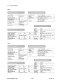
Sinewave Inverters
SWING pro 200VA and 350VA
User’s manual
1
Warranty
RIPEnergy is not manufacturer of these units . All technical information’s, data’s and dimension’s rely
on information’s given by the manufacturer. Therefore RIPEnergy AG is not responsible for the data’s
provided in this manual. Should work take place, which is not in accordance with guidelines, local
rules, instruction’s or specification’s, damage may occur. All of these matters will lead to loss of warranty. RIPEnergy AG can not accept any liability for damages or costs arising due to the use of these
inverters.
2
Distributor’s address
RIPEnergy AG, Talstrasse 2, CH-8702 Zollikon, Schweiz
Tel : ++41-(0)43-818 53 85
Fax : ++41-(0)43-818 53 87
Email: [email protected]
Internet: www.RIPEnergy.ch
3
Retail dealer’s address / Date of purchase
................................................................................................................
................................................................................................................
................................................................................................................
................................................................................................................
................................................................................................................
................................................................................................................
................................................................................................................
Manual Swing pro.doc
2/12
Version 2
Contents
1
2
3
4
5
6
7
8
9
10
11
12
Warranty ..................................................................................................................................... 2
Distributor’s address ................................................................................................................... 2
Retail dealer’s address / Date of purchase................................................................................. 2
General Information .................................................................................................................... 4
Use of this manual ...................................................................................................................... 4
Limitation of liability..................................................................................................................... 4
Warranty specifications (short form) ........................................................................................... 5
Unpacking ................................................................................................................................... 5
Environmental protection ............................................................................................................ 5
Description of the inverter........................................................................................................... 5
Block Diagram............................................................................................................................. 6
Safety Information....................................................................................................................... 6
12.1
General information ........................................................................................................... 6
12.2
Working with batteries ....................................................................................................... 7
13 Planning and mounting the inverter ............................................................................................ 7
13.1
Required power draw ........................................................................................................ 7
13.2
Installation ......................................................................................................................... 7
13.3
DC-Wiring .......................................................................................................................... 8
13.4
AC-Wiring .......................................................................................................................... 8
13.5
Grounding.......................................................................................................................... 9
14 Remote control unit..................................................................................................................... 9
15 Operation .................................................................................................................................. 10
16 LED-Indicator ............................................................................................................................ 10
16.1
Overload protection LED : (OLP) .................................................................................... 10
16.2
Over voltage protection LED: (OVP) ............................................................................... 10
16.3
Under voltage protection LED: (UVP) ............................................................................. 10
16.4
Over temp protection LED : (OTP) .................................................................................. 10
17 Maintenance ............................................................................................................................. 10
18 Technical data........................................................................................................................... 11
19 Trouble shooting ....................................................................................................................... 12
20 Further assistance and sending the unit for repair ................................................................... 12
Manual Swing pro.doc
3/12
Version 2
4
General Information
Thank you for choosing a product supplied by RIPEnergy AG. The product you have bought is manufactured to meet the highest quality standards. Our manufacturers have a very long experience in
manufacturing of high end electronic equipment.
5
Use of this manual
This user’s manual contains the information you need to install and operate this inverter correctly.
Check that you have the correct manual for your unit.
It is valid for the following units :
Sinewave Inverter Swing pro 200-12-230 and 200-24-230 and 200-48-230
Sinewave Inverter Swing pro 350-12-230 and 350-24-230 and 350-48-230
Read the manual carefully before installing or operating the inverter. If you do not understand or are uncertain about any operation or information, please contact your dealer. He
will be able to help you with an explanation or will demonstrate the operation.
The user must always have access to the user’s manual. The latest version of the manual
is provided and can be downloaded from the homepage of RIPEnergy AG.
These inverters must be only installed by qualified, authorized and trained personnel
familiar with the locally applicable standards and taking into consideration all relevant
safety guidelines and measures!
Never remove the type number plate. Important technical information required for service
or delivery of spare parts can be derived from the type number plate.
Modifications or breaking the warranty label without a written permission from RIPEnergy
AG means that warranty is lost immediately!
Always contact your dealer first if you have any problems.
6
Limitation of liability
RIPENERGY AG is not responsible or liable for any loss, damage or costs arising from operating
these inverters.
The products supplied by RIPEnergy AG are not for application’s in any medical equipment intended
for use as a component of any life support system. If products are used in such systems, a specific
written agreement between the manufacturer, RIPEnergy AG and the installer/manufacturer of the
system is needed. In addition, the manufacturer of the system must agree to indemnify RIPEnergy AG
from any claims arising from use of products supplied by RIPEnergy AG in the life support equipment.
Manual Swing pro.doc
4/12
Version 2
7
Warranty specifications (short form)
The chargers are built for RIPEnergy AG in according to the legally applicable standards. During production, and prior to delivery, all products are tested and inspected. RIPEnergy AG is looking to find
the best available products on the market. Good quality parts and the latest technology of the units will
ensure a long lasting and trouble free operation of these units.
If any problem occurs during warranty period, please contact your dealer first. He is able to serve you
with instructions and explains you how to send the unit to the nearest service center, if necessary.
Warranty can only be guaranteed if you enclose a document (Invoice or delivery documents) to the
defective units.
Damage attributable to normal wear and tear, overload or improper handling or installation is not covered by the warranty.
Modifications or breaking the warranty label without a written permission from RIPEnergy AG means
that the warranty is lost immediately!
Always return the units in it’s original package and completely assembled. A short description of the
failure/problem will help us to serve you better (see also instructions on item 17).
RIPEnergy AG is not paying for costs arising for transport of the unit or damage that arises during the
time the unit is unserviceable. The general terms of delivery and terms of sale of RIPEnergy AG are
valid.
8
Unpacking
After unpacking, carefully check the inverter for possible damage. If any damage due to transport is
visible immediately contact your dealer for further instructions.
Keep the original packing in case you need it to transport the inverter later.
9
Environmental protection
RIPEnergy AG continually commits a considerable part of its resources towards minimizing the environmental impact of its products. The inverter is manufactured with valuable materials and easy to
recycle.
10 Description of the inverter
The model Swing pro 200VA and Swing pro 350VA pure sinewave inverter supplies a 230VAC output
voltage either from a 12V, 24V or 48V DC power source. The shape of the output voltage is pure sinewave - clean power as from the grid.
The inverter design is based on state of the art high frequency technology. All functions are controlled
by a microprocessor. Extra input and output filtering to reduce EMI to extremely low levels. Reliability
features include an input fuse, thermal shutdown, current limiting and output short circuit shutdown
with automatic recovery.
The input and output is fully isolated. The superb overload capability supplies short time peak power to
start heavy equipment such as pumps and compressors.
Manual Swing pro.doc
5/12
Version 2
11 Block Diagram
12 Safety Information
12.1 General information
Read the manual carefully before installing or operating the inverter. If you do not understand or are
uncertain about any operation or information please contact your dealer. Before installation you must
be aware of local standards and rules applicable to use such equipment. For installation and use of
the inverter pay attention to local applicable standards, all relevant safety guidelines and measures.
These rules may be different to the information’s provided in this manual.
High voltages up to 1200V inside the inverter! Never open the enclosure. High voltage may harm or
even kill persons or animals. Never touch wires or blank connectors. Do not operate the inverter with
damaged or substandard wiring.
Check local standards for lightning protection of inverter systems.
No other inverter output, AC-Generator or other AC-Source may be connected to the inverters ACOutput. The inverter will be destroyed immediately!
The enclosure may heat up to 80°C! Never obstruct louvers nor place other items on the inverters
enclosure. If ventilation is not sufficient the unit may overheat and an automatic shut off may occur.
Even if DC-Wiring is not longer connected to the batteries, inbuilt large capacitors may hold DcVoltage for an extended period of time. The inverter may only be opened by skilled and authorized
personnel.
Modifications or breaking the warranty label without a written permission from RIPEnergy AG means
that warranty is lost immediately!
The inverter contains components which can produce arks and sparks. To prevent fire or explosion,
do not install or operate in compartments containing batteries or flammable materials. Never use or
operate the unit where there is danger of gas- or dust explosion.
After automatic shut down of the inverter because of any failure the inverter may switch ON automatic
again. The OFF period is depending on what causes the shut down and may vary from only seconds
to several minutes.
Manual Swing pro.doc
6/12
Version 2
12.2 Working with batteries
Using batteries in a wrong way may result in danger for personnel, animals or the environment. Check
information from battery manufacturer for safe installation and operation.
If battery acid contacts skin or clothing, wash immediately with soap and water. If acid contacts eyes,
immediately flush with running cold water for at least 20 minutes and get medical attention as soon as
possible.
Never smoke or allow a spark or flame in vicinity of batteries.
Do not drop metal tools on batteries. The resulting spark or short circuit may cause an explosion.
Remove personal metal items such as rings, bracelets, necklaces and watches when working with
batteries.
13 Planning and mounting the inverter
This section will provide you information’s about configuring and installing your inverter. Make sure
that you are aware of local rules and safety measurements.
13.1 Required power draw
Before connecting your appliances to the inverter, always check the power draw required. The inverter
is affordable to supply surge power for a short time, so as to start up electrical equipment such as
pumps, motors, etc. Some equipment needs more power while starting up.
The inverter is protected against overload and will switch off automatically when overload is applied.
As ambient temperature is above 20°C the inverters nominal power may be smaller due to reduced
cooling.
Using the inverter in high altitudes may also reduce nominal power of the inverter because of less heat
discharge. As a rule of thumb, the reduction of nominal power is approximately 1.5% per 100m elevation.
13.2 Installation
These units must be only installed by qualified, authorized and trained personnel familiar with the
locally applicable standards and taking into consideration all relevant safety guidelines and measures!
Before installing the unit check for correct DC-Voltage and power level of the inverter.
The Inverter may be installed in any position. Install the inverter in a dry, well ventilated and dust free
location. It must be installed out of reach for unauthorized personnel especially children’s. Do not install the inverter in the same compartment as the batteries.
Never use or install the inverter in locations where there is gas or explosive danger!
For proper cooling of the Inverter ensure that the airflow is not obstructed and keep a clearance distance of 2.5cm to other units. If the inverter is installed in a closed compartment the nominal power
may be reduced.
In order to keep the battery cables as short as possible (max. 6m) locate the inverter close to the DCDistribution or Battery. Be aware that during charging of batteries an explosive gas can be generated.
Manual Swing pro.doc
7/12
Version 2
13.3 DC-Wiring
Position of the switch on the front panel must be OFF.
A high power fuse must be installed direct to the battery to protect the DC-Wiring (not for Swing pro
200-12-230). DC – current according to the datasheet.
Not installing a fuse may result in melting or even burning DC-Cables in case of excessive overload or
failure of the inverter.
The way of wiring has influence on the EMC behaviour of the system. Most problems using inverter
are because of unprofessional wiring. Lay the cables in a metal duct. If this is not possible the cables
should be twisted and lay parallel to a metal bar.
To thin cable or loose connections can cause dangerous overheating of cables or terminals. Always
use DC cables of the correct size to avoid fire and other damage.
Use DC Cable with appropriate size and cable lug (see picture).
Only SWING pro 200-12-230
DC-Connector already mounted to DC-Cable. Do not remove. It is for use with cigarette lighter output
in your car. Check the fuse of your car for correct size (>15A).
Connect the cables with care to the battery/inline fuse. If possible use coloured cables. Red colour
means battery positive, while black is used for battery negative. Reversing positive and negative will
cause major damage to the inverter and is not covered by warranty.
Note: Large capacitors in the units may hold DC-Voltage for a long period of time. Also a spark may
occur while connecting the DC-cables or inserting the DC-Fuse after installation. This is normal.
If you connect other consumers to the battery contact your dealer.
13.4 AC-Wiring
Use the included AC-Connector to connect the AC-Load to the output of the inverter.
Even the inverter is protected against overload and short circuit, we recommend to use an AC-Circuit
breaker of correct size.
For safe operation it is necessary to connect earth (PE) and neutral (N) of the inverter output to central
ground of the inverter.
Even more safe is to use a 15mA or 30mA earth leakage switch in the AC-Installation.
Manual Swing pro.doc
8/12
Version 2
13.5 Grounding
The earth wire protection is only possible if the inverter enclosure is also connected to earth. Use a .
8-10mm2 cable (AWG 8) and connect it to the earth terminal of the inverter. This is also important for
lighting protection.
14 Remote control unit
The optional available remote control unit enables remote control of the inverter. The remote control
unit must be connected to the remote port located on the rear side of the inverter. When using the
remote control unit the main switch of the inverter must be in the “ON” position.
Remote port
Manual Swing pro.doc
9/12
Version 2
15 Operation
The Inverter is controlled by a single switch located on the front panel of the inverter.
Engaging
Switch to “ON-Position“. The green Power LED will illuminate and you will hear three beep.
The Inverter is ready to use.
Power down
Switch to „OFF-Position“. All LED’s are dark. The inverter is OFF.
Remark
Even if the inverter is switched to off, it is not disconnected from the battery. It still draws very little
power from the battery. If you don’t need the inverter for an extended period disconnect it from the
battery to avoid low discharge of battery.
16 LED-Indicator
16.1 Overload protection LED : (OLP)
The overload indicator indicates that the power inverter has shut itself down. When output voltage
over continue power, then must return to operate manually.
16.2 Over voltage protection LED: (OVP)
The over voltage indicator indicates that the power inverter has shut itself down because its input voltage exceeded the maximum input voltage.
16.3 Under voltage protection LED: (UVP)
The under voltage indicator indicates that the power inverter has shut itself down because its input
voltage fell below minimum input voltage.
16.4 Over temp protection LED : (OTP)
The over temp indicator indicates that the power inverter has shut itself down because its temp has
become overheated. The power inverter may overheat because it has been operated at power levels
above its rating, or because it has been installed in a location which does not allow it to dissipate heat
properly. The power inverter will automatically back up, once it has cooled off.
17 Maintenance
Only little maintenance is required to keep your inverter and system operating reliable. The inverter
must be switched off during maintenance and/or repair activities. It also must be secured against unexpected and unintentional switching on. Therefore switch off the connection between batteries and
inverter and be sure that third parties cannot reverse the measures taken.
The following Steps must be undertaken at least once a year. Check cable and wires for damage and
if they are still firmly connected. Defects such as loose connections ore damaged cables etc. must be
corrected immediately. Keep the inverter dry, clean it from dust in order to ensure good heat discharge.
Manual Swing pro.doc
10/12
Version 2
18 Technical data
200VA
350VA
Manual Swing pro.doc
11/12
Version 2
19 Trouble shooting
Warning – Never remove the cover of the inverter! Do not self repair the inverter, no serviceable
parts are inside the unit.
No function
DC-Low voltage
Check LED-Display to identify the reason.
According the failure indicated by the display see sections below to solve the
problem.
Check wiring for correct size, damage or loose screws.
Check batteries, battery fuse or fuse installed on AC-output.
If switch is in remote position but no remote cable is connected , switch it to the
„ON-Position“.
The battery voltage dropped below 1.75V/Cell.
Check battery fuse.
Charge the battery – if charging is not solving the problem maybe the battery is
defect.
The wiring may be too thin or check installation for loose connections.
Note: If battery voltage rises above 2.1V/Cell, the inverter restarts automatically.
DC-Over voltage
Over temperature
The battery voltage is above 2.55V/Cell.
Remove the battery charger and stop charging the battery.
Note: If battery voltage is dropping below 2.5V/Cell the inverter restarts automatically.
If load is smaller than nominal power of inverter – check if ventilation of the
inverter is blocked. Maybe the ambient temperature is too high.
If load is exceeding nominal power of inverter – reduce the load.
Note: The inverter will switch on automatically if temperature of the inverter is
within normal operating temperature range.
Overload
Reduce load. Remove unnecessary consumers.
Reset the inverter with the front panel switch OFF than ON.
Other failures
Check system for correct grounding or contact your dealer.
V/Cell: The nominal voltage using lead acid batteries is 2VDC/Cell. Example: A 12V-Battery contains 6
single cells, a 24V-Battery contains 12 single cells etc.
20 Further assistance and sending the unit for repair
In the rare case the unit is not working contact your dealer providing him some details as:
1.
2.
3.
4.
5.
Check Battery voltage, wiring and display for possible failures.
Note: Type of unit and serial number.
Now call your dealer or nearest service center. They will help you with further instructions.
If he recommends to send the unit back for repair, use the original packing.
Include a copy of the invoice (Warranty repair is only possible with a copy of invoice or certificate
showing date of purchase) and a short notice about your system and the failure observed.
6. In case you have to send the unit over state borders please make sure to fill the correct papers
needed for customs. To reduce time and save money, contact the consignee how to declare the
delivery. Arising costs for customs have to be paid by the sender.
7. Transport costs to send the unit back to RIPEnergy AG are not covered from Warranty.
Manual Swing pro.doc
12/12
Version 2