1
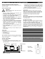
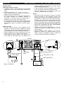
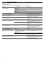
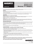
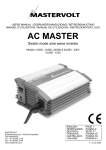
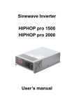
USER’S MANUAL INV10120700 / INV20120700 / INV30120700 INV10121000 / INV20121000 / INV10121500 INV20121500 / INV30121500 / INV10240700 INV20240700 / INV10241000 / INV10241500 INV20121500 Pure sine wave inverter MARINCO N85W12545 Westbrook Crossing Menomonee Falls, WI 53051 www.marinco.com ENGLISH: NEDERLANDS: DEUTSCH: FRANÇAIS: CASTELLANO: ITALIANO: PAGE 1 PAGINA 13 SEITE 25 PAGINA 37 PÁGINA 49 PÁGINA 61 10000006303/05 ENGLISH 1 QUICK INSTALLATION INSTRUCTIONS This section provides a brief overview of a basic stand alone installation of the Inverter 5 Connect the battery to the DC input. Integrate a fuse holder in the positive battery wire, but do not place the fuse yet. However; please review the entire manual for connection of additional features and to ensure best performance and years of trouble-free operation. Use isolated tools! Read safety instructions (page 3) 2 Disconnect the electrical power: 3 Switch off all consumers, Switch off all charging systems. Remove the battery fuse. Check with a suitable voltmeter whether the DC installation is voltage free. Move the main switch of the Inverter to the OFF position Red wire POS (+) Connect red wire to +, black wire to –. Incorrect polarity will damage the Inverter! 6 Connect the AC load to the AC socket. 120V: 4 Mount the Inverter with four screws to a solid surface. Allow at least 10 cm / 4 inch space around the apparatus! Black wire NEG (–) 230V: For safe installation, The chassis ground terminal (see Figure 1, reference 7) must be connected to the central grounding point of the vehicle/ ship The neutral conductor (N) of the AC output of the Inverter must be connected to the safety ground (PE/GND) and a ground fault circuitinterrupter (GFCI) must be integrated in the wiring of the AC output Refer to section NEUTRAL GROUNDING of this user’s manual 7 Check all wiring. If all wiring is OK: Place the inverter fuse. Switch on the Inverter. 2 USER’S MANUAL 700, 1000, 1500 WATT INVERTER PRODUCT DESCRIPTION AND APPLICATION The Marinco inverters convert a DC voltage to a pure AC sine wave voltage. SAFETY INSTRUCTIONS WARNING! Before using the Inverter, read and save the safety instructions Use the Inverter following the instructions and specifications stated in this manual. Connections and safety features must be executed according to the locally applicable regulations Operation of the Inverter without proper grounding may lead to hazardous situations! Use DC-cables with an appropriate size. Integrate a fuse in the positive wiring and place it nearby the battery. Refer to the specifications. If the positive and negative wires on the DC-input (battery) are exchanged, the Inverter will be damaged. Damage of this kind is not covered by guarantee. Check whether all connections are connected correctly before placing the fuse. Do not connect the AC-output of the inverter to an incoming AC source. Never connect the Inverter in parallel with any other inverter. Never open the housing as high voltages may be present inside! The neutral conductor (N) of the AC output of the Inverter must be connected to the safety ground (PE/GND) and a ground fault circuit-interrupter (GFCI) must be integrated in the wiring of the AC output. See below for model specific information. Refer to locally applicable regulations on these issues! 120V models With the 120V models the neutral conductor of the AC output circuit of the Inverter is internally connected to the safety ground during inverter operation automatically and a ground fault circuit-interrupter (GFCI) is already integrated in the AC output circuit of the Inverter. 230V models With the 230V models there is no connection made inside the inverter between either the line or neutral conductor to the safety ground. DIP SWITCH SETTINGS See Figure 1, ref. 6. Under normal circumstances there is no need to change the default settings of the DIP switches: the inverter is immediately ready for use. To save energy from the battery in no load operation, DIP switches S1, S2 and S3 can be used to adjust the Power Saving Mode. The Power Saving Mode scans the output and when it detects a load which is higher than the selected threshold value, the inverter is switched on automatically. Model UNPACKING The delivery consists of the following parts: The inverter This user’s manual Four ring terminals After unpacking, check the Inverter for possible damage. Do not use the Inverter if it is damaged. If in doubt, contact your supplier. NEUTRAL GROUNDING For safe installation, The chassis ground terminal (see Figure 2, ref. 7) must be connected to the central grounding point of the vehicle/ ship 1 Main switch 2 AC output ENGLISH Power Saving Mode 700 1000/1500 DISABLE DISABLE 15W 20W 25W 40W 40W 55W 50W 75W 65W 95W 75W 115W 85W 135W S1 S2 S3 0 1 0 1 0 1 0 1 0 0 1 1 0 0 1 1 0 0 0 0 1 1 1 1 DIP switch S4 is used to select the output frequency Output frequency S4 50Hz 0 60Hz 1 LED indicators 3 4 R AC output 120V models: 5 6 DIP switches AC output 230V models: Figure 1: Front side 3 ENGLISH USER’S MANUAL 700, 1000, 1500 WATT INVERTER 24V input voltage). Also check that the output voltage satisfies loading requirements A DC fuse holder must be integrated in the positive wiring. The DC fuse should be placed last of all. Use four Ø4.5mm (No. 8) screws to mount the Inverter to a solid surface. See Figure 3. INSTALLATION Choosing a location to install Install the Inverter in a well-ventilated room protected against rain, snow, spray, vapour, bilge, moisture and dust. Ambient temperature: –25 ... 40°C / –13…104°F; Never use the Inverter at a location where there is danger of gas or dust explosions Mount the Inverter in such a way that obstruction of the airflow through the ventilation openings is prevented. No objects must be located within a distance of 10 cm / 4 inch around the Inverter. Do not install the Inverter in the same compartment as the batteries. Do not mount the Inverter straight above the batteries because of possible corrosive sulphur fumes. Wiring Connect DC wiring as shown in Figure 2: the black terminal (9) NEG (–) to the negative (–) pole of the power source / battery, the red terminal (8) POS (+) to the positive (+) pole of the power source/ battery. Integrate a DC fuse holder in the positive wiring, but do not place the fuse yet. Assemble the DC wiring exactly as indicated. Do not place anything between the ring terminal and the terminal surface. Make sure that all DC connections are tight. Recommended torque: 11.7-13 Nm / 104-115 InLbs Chassis ground: Use a cable AWG8 / 6 mm² to connect the CHASSIS GROUND terminal (7) to the central ground. Remote operation switch (option). If you want to operate the Inverter on a remote location, you can install a switch as indicated in Figure 2. When the contact is closed, the Inverter is switched on. Before you start Be sure that the output of the supplying source (battery) is switched off during installation. Also be sure that no consumers are connected to the battery during installation, to prevent hazardous situations. Before installing the Inverter make sure the main switch (Figure 1, ref. 1) is set to the OFF position. Check that the battery voltage is the same as the input voltage of the Inverter (e.g. 24V battery for a Inverter 10 7 Remote operation switch (option) 8 9 Red wire POS (+) Grounding point Fuse holder + Fuse Black wire NEG (–) OFF Figure 2: rear side 4 ON Battery USER’S MANUAL 700, 1000, 1500 WATT INVERTER COMMISSIONING AFTER INSTALLATION 1. Check the polarity of the DC-connections. Do not place the DC fuse if the polarity is not correct. 2. Place a DC-fuse (see SPECIFICATIONS) in the fuse holder. When placing this fuse, a spark may occur, caused by internal capacitors of the Inverter. This is normal. 3. AC voltage: the load can be plugged into the ACoutput (Figure 1, ref. 2) directly. OPERATION Switching on: Move the main switch (Figure 1, ref. 1) to “ON”. The Inverter will start a self-test indicated by two beeps from the buzzer and flashing LED indicators. This may last for approximate two seconds. Finally the buzzer will produce another beep and the Inverter will switch on, indicated by two green LED indicators.. Now the Inverter is ready to supply load connected to the AC-output. Switching off: Move the main switch (Figure 1, ref. 1) to the “OFF” position. Note that switching off the Inverter does not break the connection to the batteries! Remote operation: The Inverter can be operated on a remote location by means of an optional remote switch. Move the main switch (Figure 1, ref. 1) to the “REMOTE” position. When the remote contact is closed, the Inverter is switched on. GFCI (120V models only): In case of a ground fault, the Ground-Fault Circuit Interrupter (GFCI) trips and cuts off the AC output. To switch on the AC output again, push the reset button (Figure 1, ref. R) LED indicators See Figure 1. The operation of the inverter is made visible by means of LED indicators (3), (4) and (5). “INPUT LEVEL” (ref. 3) displays the input voltage of the inverter: Indication of the LED RED blinking slow RED ORANGE GREEN ORANGE blinking RED blinking fast Input voltage (V) 12V models 24V models 10.3~10.6 20.5~21.2 10.6~11.0 21.2~21.8 11.0~12.1 21.8~24.1 12.1~14.2 24.1~28.6 14.2~15.0 28.6~30.0 > 15.0 > 30.0 ENGLISH “LOAD LEVEL” (ref. 4) shows the output load level: LED indication Model LED off GREEN ORANGE RED RED blinking Power level (W) 700W 0-56 56-230 230-525 525-672 >672 1000W 0-80 80-330 330-750 750-960 >960 1500W 0-120 120-495 495-1125 1125-1450 >1450 “STATUS” (ref. 5) shows the operation mode of the inverter. As long this LED isn’t illuminated red, no failure is detected: the inverter is operating normally. If an error occurs, it is detected by the apparatus itself: the “STATUS” LED turns red. Indication of the LED ▬▬▬▬▬▬▬▬▬▬▬ GREEN, uninterrupted ▬ ▬ ▬ ▬ GREEN, slow blinking ▬ ▬ ▬ ▬ ▬ ▬ ▬ RED, fast blinking ▬ ▬ ▬ ▬ RED, slow blinking -- -- -- -- -RED, intermittently blinking ▬▬▬▬▬▬▬▬▬▬▬ RED, uninterrupted Meaning Power OK Power saving mode, see DIP SWITCH SETTINGS DC-input voltage too high DC-input voltage too low Internal temperature too high Overload / short circuit Maintenance No specific maintenance is required. If necessary, use a soft clean cloth to clean the Inverter. Never use any liquids, acids and/or scourers. Check the wiring on a regular base. Defects such as loose connections, burnt wiring etc. must be corrected immediately. DECOMMISSIONING Proceed as follows for decommissioning of the inverter: 1. Move the main switch (Figure 1, ref. 1) to the OFF position. 2. Remove the DC fuse. Be sure that others can not reverse this action taken. 3. Now the inverter can be demounted in a safe way. 5 ENGLISH USER’S MANUAL 700, 1000, 1500 WATT INVERTER TROUBLE SHOOTING Consult an installer, if you cannot solve the problem by means of the table below. Problem No output voltage, all LED indicators are off No output voltage, STATUS LED (ref 5) is slowly blinking green. No output voltage, STATUS LED (ref 5) is fast blinking red. Possible cause Main switch (ref 1) is set to the OFF position Main switch (ref 1) is set to REMOTE but no remote present The remote switch is off (if applied) DC fuse blown Inverter is in power saving mode DC input voltage too high No output voltage, STATUS LED is slowly blinking red. DC input voltage too low (flat battery) No output voltage, STATUS LED is intermittently blinking red. AC Output is overloaded Airflow insufficient No output voltage, STATUS LED is uninterruptedly lit red. AC output overloaded or short circuit. No output voltage, STATUS LED is uninterruptedly lit green Inverter switches on and off. STATUS LED is slowly blinking red. (120V models only:) internal GFCI tripped DC input voltage too low because of voltage drop across the DC cables due to too long or too narrow cables Flat battery Loose or corroded connections Some loads like televisions and clocks do not operate correctly 6 Wrong setting of output frequency What to do? Set the main switch (ref 1) in ON position Set the main switch (ref 1) in ON position Close the remote operation switch Replace the fuse Increase the load or adjust the power setting mode; See DIP SWITCH SETTINGS Check battery voltage; switch off charger. The inverter will switch on again when the input voltage is <14.3 / <28.6V Charge the battery. The inverter will switch on again when the input voltage is >12.7V / >25.2V Reduce the load and let the inverter cool down. The inverter will switch on again when the internal temperature is < 45°C / 113°F Check the airflow through the inverter. The operation of the cooling fan may not be blocked. Reduce the load and/or check the AC wiring for possible short circuits. Then reset the inverter manually by switching the main switch (ref. 1) off and on again Press the reset button of the GCFI (Figure 1, ref. R) Reduce the length of the DC cables or use cables with a larger gauge. Disconnect the load and recharge the battery Tighten the connections; burnt cables must be corrected immediately. Check the specified input frequency of the load with the output frequency of the Inverter. If necessary, adjust the output frequency. See DIP SWITCH SETTINGS. USER’S MANUAL 700, 1000, 1500 WATT INVERTER ENGLISH SPECIFICATIONS 700W models Model Inverter 12/700-120V US 24/700-120V US 12/700-230V Br 12/700-230V EU 24/700-230V EU Part number: Function of the apparatus: Supplier: INV20120700 INV20240700 INV30120700 INV10120700 INV10240700 Conversion of a DC voltage to a pure AC sine wave voltage Marinco 12VDC (10.5-15.0VDC) 24VDC (21.0-30.0VDC) 12VDC (10.5-15.0VDC) 12VDC (10.5-15.0VDC) 24VDC (21.0-30.0VDC) Tamb=40°C, cosφ 1 700W 700W 700W 700W 700W Max. peak load 1400W 1400W 1400W 1400W 1400W Input voltage: Nom Power Output waveform True sine wave (THD <3%) Maximum efficiency 89% 91% 91% 91% 93% Output voltage 120V+/-5% 120V+/-5% 230V ±3% 230V ±3% 230V ±3% Frequency (selectable) 60Hz ±0.05Hz 60Hz ±0.05Hz 60 Hz ±0.05Hz 50 Hz ±0.05Hz 50 Hz ±0.05Hz AC outlet GFCI Dimensions See chapter Dimensions Schuko / UK / Australia / Universal Weight: 2.7 kg / 5.4 lbs 2.7 kg / 5.4 lbs 2.7 kg / 5.4 lbs 2.7 kg / 5.4 lbs 2.7 kg / 5.4 lbs Protection degree IP21 IP21 IP21 IP21 IP21 Technology Shut down voltage low battery Restart voltage low battery Shut down voltage high battery Restart voltage high battery Maximum allowed ripple on DC Input current @ nominal load External DC fuse required Recommended battery capacity: DC cable (up to 3m / 10ft) No load power consumption: Off mode HF / Switch mode 10.2V (±0.5V) 20.3V (±0.5V) 10.2V (±0.5V) 10.2V (±0.5V) 20.3V (±0.5V) 12.7V (±0.5V) 25.2V (±0,5) 12.7V (±0.5V) 12.7V (±0.5V) 25.2V (±0,5) 15.3V (±0.5V) 30.6V (±0.5V) 15.3V (±0.5V) 15.3V (±0.5V) 30.6V (±0.5V) 14.3V (±0.5V) 28.6V (±0.5V) 14.3V (±0.5V) 14.3V (±0.5V) 28.6V (±0.5V) 64A 32A 64A 64A 32A 100A 50A 100A 100A 50A ≥100Ah ≥55Ah ≥100Ah ≥100Ah ≥55Ah 25mm² - 4AWG 16mm² - 6AWG 25mm² - 4AWG 25mm² - 4AWG 16mm² - 6AWG 0mA 0mA 0mA 0mA 0mA 5% RMS Power Saving Mode 0.25A 0.15A 0.25A 0.25A 0.15A ON @ Unom Operating temperature specified (will meet specified tolerances) Practical operating temperature (may not meet specified tolerances) Cooling: Non-operating temperature (storage temperature) 1.25 A 0.64A 1.20A 1.20A 0.60A Full specifications at ambient temperature 0 to 40°C (32 to 104°F), Derating with 5%/°C (3%/°F) at 40 to 60°C (104 to 140°F), Shutdown at over temperature, auto recover after cooling down Ambient temperature -25 to 40°C (-13 to 104°F) Derating with 5%/°C (3%/°F) at 40°C to 60°C (104 to 140°F). Shutdown at over temperature, auto recover after cooling down Temperature and load regulated fan Ambient temperature -30°C to 70°C / -22°F to 158°F Safety: Protected against humidity and condensing air by conformal coating on both sides of all PCB’s. Max 95% relative humidity, non-condensing. Meet UL458 EN60950-1 EMC: FCC class A Relative humidity EN55022, EN61000-3-2, EN61000-3-3, EN55024 e-mark N/A Protections: Overload, short circuit, over / under voltage, over temperature N/A N/A Reversed polarity: Internal fuse, reversed polarity may lead to permanent damage N/A N/A 7 ENGLISH USER’S MANUAL 700, 1000, 1500 WATT INVERTER SPECIFICATIONS 1000W models Model Inverter 12/1000-120V USA 12/1000-230V EU 24/1000-230V EU Part number: Function of the apparatus: Supplier: INV20121000 INV10121000 INV10241000 Input voltage: Nom Power 12VDC (10.5-15.0VDC) 12VDC (10.5-15.0VDC) 24VDC (21.0-30.0VDC) Tamb=40°C, cosφ 1 1000W 1000W 1000W Max. peak load 2000W 2000W 2000W Conversion of a DC voltage to a pure AC sine wave voltage Marinco Output waveform True sine wave (THD <3%) Maximum efficiency 89% 91% 94% Output voltage 120V+/-5% 230V ±3% 230V ±3% Frequency (selectable) 60Hz ±0.05Hz 50 Hz ±0.05Hz 50 Hz ±0.05Hz AC outlet GFCI Schuko / UK / Australia / Universal Dimensions See chapter Dimensions Weight: 4.0 kg / 8.8 lbs 4.0 kg / 8.8 lbs 4.0 kg / 8.8 lbs Protection degree IP21 IP21 IP21 Technology Shut down voltage low battery Restart voltage low battery Shut down voltage high battery Restart voltage high battery Maximum allowed ripple on DC Input current @ nominal load External DC fuse required Recommended battery capacity: DC cable (up to 3m / 10ft) No load power consumption: Off mode HF / Switch mode 10.2V (±0.5V) 10.2V (±0.5V) 20.3V (±0.5V) 12.7V (±0.5V) 12.7V (±0.5V) 25.2V (±0.5V) 15.3V (±0.5V) 15.3V (±0.5V) 30.6V (±0.5V) 14.3V (±0.5V) 14.3V (±0.5V) 28.6V (±0.5V) 92A 92A 46A 150A 150A 80A ≥120Ah ≥120Ah ≥100Ah 35mm² - 2AWG 35mm² - 2AWG 25mm² - 4AWG 0mA 0mA 0mA Power Saving Mode 0.25A 0.25A 0.15A ON @ Unom Operating temperature specified (will meet specified tolerances) Practical operating temperature (may not meet specified tolerances) Cooling: Non-operating temperature (storage temperature) 1.43A 1.25A 0.65A 5% RMS Full specifications at ambient temperature 0 to 40°C (32 to 104°F), Derating with 5%/°C (3%/°F) at 40 to 60°C (104 to 140°F), Shutdown at over temperature, auto recover after cooling down Ambient temperature -25 to 40°C (-13 to 104°F) Derating with 5%/°C (3%/°F) at 40°C to 60°C (104 to 140°F). Shutdown at over temperature, auto recover after cooling down Temperature and load regulated fan Ambient temperature -30°C to 70°C / -22°F to 158°F Safety: Protected against humidity and condensing air by conformal coating on both sides of all PCB’s. Max 95% relative humidity, non-condensing. Meet UL458 EN60950-1 EMC: FCC class A EN55022, EN61000-3-2, EN61000-3-3, EN55024 e-mark N/A N/A Protections: Overload, short circuit, over / under voltage, over temperature Reversed polarity: Internal fuse, reversed polarity may lead to permanent damage Relative humidity 8 N/A USER’S MANUAL 700, 1000, 1500 WATT INVERTER ENGLISH SPECIFICATIONS 1500W models Model Inverter 12/1500-120V US 12/1500-230V Br 24/1500-230V Br 12/1500-230V EU 24/1500-230V EU Part number: Function of the apparatus: Supplier: INV20121500 INV30121500 INV30241500 INV10121500 INV10241500 Conversion of a DC voltage to a pure AC sine wave voltage Marinco 12VDC (10.5-15.0VDC) 12VDC (10.5-15.0VDC) 24VDC (21.0-30.0VDC) 12VDC (10.5-15.0VDC) 24VDC (21.0-30.0VDC) Tamb=40°C, cosφ 1 1500W 1500W 1500W 1500W 1500W Max. peak load 3000W 3000W 3000W 3000W 3000W Input voltage: Nom Power Output waveform True sinewave (THD <3%) Maximum efficiency 88% 90% 93% 90% 93% Output voltage 120V+/-5% 230V+/-3% 230V ±3% 230V ±3% 230V ±3% Frequency (selectable) 60Hz ±0.05Hz 60Hz ±0.05Hz 60 Hz ±0.05Hz 50/60 Hz ±0.05Hz 50/60 Hz ±0.05Hz AC outlet GFCI Schuko / UK / Australia / Universal Dimensions See chapter Dimensions Weight: 4.8 kg / 10.6 Lbs 4.8 kg / 10.6 Lbs 4.8 kg / 10.6 Lbs 4.8 kg / 10.6 Lbs 4.8 kg / 10.6 Lbs Protection degree IP21 IP21 IP21 IP21 IP21 Technology Shut down voltage low battery Restart voltage low battery Shut down voltage high battery Restart voltage high battery Maximum allowed ripple on DC Input current @ nominal load External DC fuse required Recommended battery capacity: DC cable (up to 3m / 10ft) No load power consumption: Off mode HF / Switch mode 10.2V (±0.5V) 10.2V (±0.5V) 20.3V (±0.5V) 10.2V (±0.5V) 20.3V (±0.5V) 12.7V (±0.5V) 12.7V (±0.5V) 25.2V (±0,5) 12.7V (±0.5V) 25.2V (±0,5) 15.3V (±0.5V) 15.3V (±0.5V) 30.6V (±0.5V) 15.3V (±0.5V) 30.6V (±0.5V) 14.3V (±0.5V) 14.3V (±0.5V) 28.6V (±0.5V) 14.3V (±0.5V) 28.6V (±0.5V) 125A 125A 64A 125A 64A 200A 200A 100A 200A 100A ≥150Ah ≥150Ah ≥100Ah ≥150Ah ≥100Ah 50mm² - 1/0AWG 50mm² - 1/0AWG 35mm² - 2AWG 50mm² - 1/0AWG 35mm² - 2AWG 0mA 0mA 0mA 0mA 0mA 5% RMS Power Saving Mode 0.28A 0.28A 0.15A 0.28A 0.15A ON @ Unom Operating temperature specified (will meet specified tolerances) Practical operating temperature (may not meet specified tolerances) Cooling: Non-operating temperature (storage temperature) 1.45A 1.40A 0.70A 1.40A 0.70A Full specifications at ambient temperature 0 to 40°C (32 to 104°F), Derating with 5%/°C (3%/°F) at 40 to 60°C (104 to 140°F), Shutdown at over temperature, auto recover after cooling down Ambient temperature -25 to 40°C (-13 to 104°F) Derating with 5%/°C (3%/°F) at 40°C to 60°C (104 to 140°F). Shutdown at over temperature, auto recover after cooling down Temperature and load regulated fan Ambient temperature -30°C to 70°C / -22°F to 158°F Safety: Protected against humidity and condensing air by conformal coating on both sides of all PCB’s. Max 95% relative humidity, non-condensing. Meet UL458 EN 60950-1 EMC: FCC class A EN55022, EN61000-3-2, EN61000-3-3, EN55024 e-mark N/A N/A Protections: Overload, short circuit, over / under voltage, over temperature Reversed polarity: Internal fuse, reversed polarity may lead to permanent damage Relative humidity N/A N/A N/A 9 ENGLISH USER’S MANUAL 700, 1000, 1500 WATT INVERTER 700 Watt 163 [6.4] 1000 Watt 166 [6.5] 1500 Watt 175 [6.9] SINE WAVE INVERTER I 0 INPUT LEVEL ON LOAD LEVEL OFF STATUS REMOTE FREQ. S4 S3 S2 S1 PWR. SAV. O AC OUTPUT 700 Watt 179 [7.0] 1000 Watt 182 [7.2] 1500 Watt 191 [7.5] Figure 3 Dimensions in mm [inch] ORDERING INFORMATION Part number INVR-1 10 Description Remote panel for Marinco inverter I 700 Watt 71.5 [2.8] 1000 Watt 88 [3.5] 1500 Watt 88 [3.5] 700 Watt 151 [5.9] 1000 Watt 154 [6.0] 1500 Watt 163 [6.4] 196 [7.7] 700 Watt: 273 [10.8] 1000 Watt: 340 [13.4] 1500 Watt: 370 [14.6] 700 Watt: 33.5 [1.3] 1000 Watt: 43.5 [1.7] 1500 Watt: 43.5 [1.7] DIMENSIONS USER’S MANUAL 700, 1000, 1500 WATT INVERTER GUARANTEE TERMS Marinco guarantees that this product was built according to the legally applicable standards and stipulations. During production and before delivery all products are exhaustively tested and controlled. If you fail to act in accordance with the regulations, instructions and stipulations in this user’s manual, damage can occur and/or the product will not fulfil the specifications. This may mean that the guarantee will become null and void. The guarantee is limited to the costs of repair and/or replacement of the product by Marinco only. Costs for installation labour or shipping of the defective parts are not covered by this guarantee. ENGLISH For making an appeal on warranty you can directly contact your supplier, mentioning your complaint, application, date of purchase and part number / serial number. The standard guarantee period is 2 years. LIABILITY Marinco cannot be held liable for: Possible errors in this manual and the consequences of these. Damage due to use that is inconsistent with the purpose of the product. EC DECLARATION OF CONFORMITY We, Manufacturer Address Marinco N85 W12545 Westbrook Crossing Menomonee Falls, WI 53051 USA Represented in the EU by: Address: Mastervolt B.V. Snijdersbergweg 93 1105 AN Amsterdam The Netherlands declare under our sole responsibility that products: INV10120700 INV10240700 INV10121000 INV10241000 INV10121500 INV10241500 Marinco Inverter 12/700-230V EU Marinco Inverter 24/700-230V EU Marinco Inverter 12/1000-230V EU Marinco Inverter 24/1000-230V EU Marinco Inverter 12/1500-230V EU Marinco Inverter 24/1500-230V EU are in conformity with the provisions of the following EU directives: 2004/108/EC (EMC Directive) 2006/95/EC (Low Voltage Directive) 2011/65/EU (RoHS Directive) The following harmonised standards have been applied: Generic emission standard: Generic Immunity standard: Low voltage standard: EN 55022: 2010 EN 55024: 2010 EN 60950-1:2006 + A11:2009 + A1:2010 Amsterdam, 19 December 2013, H.A. Poppelier Manager New Product Development 11 MARINCO N85W12545 Westbrook Crossing Menomonee Falls, WI 53051 Phone 800-307-6702 or 262-293-1700; Fax: 262-293-7022 Email: [email protected] 12