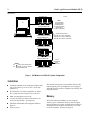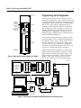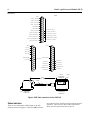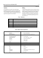
1
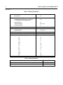
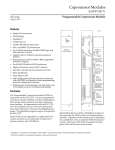
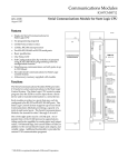
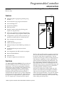
Programmable Controller AD693SLP300 State Logic Processor Module (SLP) GFK-0733A February 1994 a45130 Features OK D Natural English Language Programming using ECLiPS Î Î D Structured State Logic program architecture D Advanced Diagnostics STATE LOGIC PROCESSOR D Simulation capabilities D PID Loop control D Handles complex math easily (floating point, square root, trig functions) Î Î D Allows any combination of Natural English State Logic and Ladder Logic programs in same system D Configurable to operate with any IC693 PLC system that uses the model 331 or model 341 CPU D Up to 512 inputs and 512 outputs D CCM2 Protocol D 8 Mhz, 80C188 microprocessor D 46 Kbytes battery-backed CMOS logic memory on board D One RS-422/RS-485 port and one RS-232 serial port D Soft configuration (No DIP switches or jumpers) D Restart/ResetPushbutton D OK Status LED D Occupies a single slot in an IC693 rack Functions The State Logic Processor Module (SLP) provides real time multi-tasking control for machine and process applications. It can also be programmed to perform computations, data acquisition, data communications and operator interface functions. The SLP is programmed using the English Control Language Programming System (ECLiPS) software package. It communicates with the PLC CPU over the backplane and can access user and system data. Many SLPs can be supported in a single IC693 PLC system and each SLP can support up to 512 inputs and 512 outputs. The PLC CPU and SLP modules together in the IC693 PLC provide a dual processor architecture which can be used in a wide variety of applications. The SLP provides total state logic control, including diagnostic and simulation capablities, for those applications requiring reduced development and startup times. For those applications where both ladder logic and state logic programming is desired, the dual processor architecture allows a user to create both ladder logic and state logic application programs in any combination for efficient parallel processing solutions. In IC693 PLC ladder logic control systems, the SLP module can be added to provide high level machine and process level diagnostics which can drastically reduce total system downtime. Also, the SLP module can provide machine or process simulation capabilities to IC693 PLC ladder logic control systems to help reduce debug and startup times. IBM is a registered trademark of International Business Machines Corporation 2 State Logic Processor Module (SLP) GFK-0733A Î Î Î Î ÎÎ ÎÎ ÎÎÎÎÎÎ a45126 CPU BASEPLATE C S P L U P PC DISCRETE/ANALOG/OPTION Î Î Î Î Î Î ÎÎÎÎÎÎÎÎ ÎÎ Î Î Î Î Î ÎÎ ÎÎÎÎÎÎÎÎ ÎÎÎÎÎÎÎÎ ÎÎ ÎÎ ÎÎ ÎÎÎÎÎÎ Î Î ÎÎ Î Î ÎÎ ÎÎ Î ÎÎÎÎ EXPANSION BASEPLATE DISCRETE/ANALOG/OPTION EXPANSION BASEPLATE NOTE TOTAL MAXIMUM DISTANCE FROM MAIN BASEPLATE TO LAST EXPANSION BASEPLATE IS 50 FEET (15 METERS) I/O EXPANSION CABLES IC693CBL300 3 FEET (.9 METERS) IC693CBL301 6 FEET (I.8 METERS) IC693CBL302 50 FEET (15 METERS) DISCRETE/ANALOG/OPTION EXPANSION BASEPLATE DISCRETE/ANALOG/OPTION Î Î Î Î ÎÎ Î ÎÎ Î Î Î ÎÎÎÎÎ ÎÎ ÎÎ ÎÎ EXPANSION BASEPLATE LEGEND: SLP STATE LOGIC PROCESSOR CPU MODEL 331 OR 341 CENTRAL PROCESSING UNIT I/O BUS TERMINATOR PLUG 1C693ACC307 DISCRETE/ANALOG/OPTION Figure 1. SLP Module in an IC693 PLC System Configuration Installation D Installation should not be attempted without referring to the State Logic Processor User’s Guide (see reference 1). D The IC693 SLP can only be installed in an IC693 The module should power up and blink the top LED, indicating that power up diagnostics are in progress. When the diagnostics have completed successfully the top LED stays on. PLC system that uses a model 331 or 341 CPU. D Make sure baseplate power is off. D Connect the battery to either of the battery connectors on the module. (See figure 2) D Install the SLP Module in the baseplate. (Refer to figure 1) D Turn on power. Memor y The SLP module has 46 Kbytes of user program memory space. Additional memory exists for Input, Output, Register, and other variable data (see table 3). The battery which supports this memory is located on the SLP module as shown in figure 2. State Logic Processor Module (SLP) 3 GFK-0733A Programming and Configuration a45131 OK BD OK ÎÎ CURRENTLY INSTALLED BATTERY CONNECTOR RESTART ÎÎ ÎÎ ÎÎ ÎÎÎÎ ÎÎ OPEN REPLACEMENT BATTERY CONNECTOR There are no user DIP switches or jumpers on this module for configuration. However, the module must be configured into the overall PLC system using IC641 configurator software (reference 4). An IBM-compatible PC-XT or AT computer with the ECLiPS programming system software installed is connected to port 1, (top port) as shown in figure 3. Port 1 is the default programming port, but the SLP can also be configured to be programmed through port 2. The Default setting is 19,200 bps. Port 1 is an RS-232 port; Port 2 is an RS-422/RS-485 port. BATTERY Port communication speed, parity, stop bits, and other port parameters can be configured independently for operation with a variety of serial devices such as operator interfaces, bar code readers, weigh scales, etc. One of the two ports can also be configured to communicate with the CCM2 protocol as a slave, typically for use with operator interface terminals. PORTS 1 AND 2 SLP 300 Signals and their pins for both ports 1 and 2 are provided on the SLP’s single 25 pin connector. A WYE cable provided with the SLP module breaks out the single connector to two ports, 1 and 2, as shown in figures 3 and 4. Refer to the State Logic Processor User’s Guide (reference 1) for details of operation. Figure 2. State Logic Processor Module User Details IC647 PROGRAMMER AND IBM PS/2 25-PIN MALE Î ÎÎ ÎÎ Î ÎÎ Î Î ÎÎ PIN IC690CBL705 PIN 2 3 4 5 8 20 7 TXD RXD RTS CTS DCD DTR GND 25-PIN FEMALE 3 2 5 20 8 1 7 RXD TXD CTS DTR DCD SHLD GND 25-PIN MALE ÎÎ Î Î Î Î ÎÎ PCM IC693 SLP 25-PIN FEMALE PC RS-232 (DEFAULT PORT) ÎÎ ÎÎÎÎÎÎÎÎÎ ÎÎÎÎÎÎÎÎÎ ÎÎÎÎÎÎÎÎÎ Î Î a45128 WYE CABLE ÎÎ ÎÎ Î PCM COMM. CABLE IC693CBL305B ECLiPS PROGRAMMING SOFTWARE Figure 3. Development PC System Running ECLiPS and its Connection to SLP 4 State Logic Processor Module (SLP) ÎÎÎ ÎÎÎ ÎÎ ÎÎÎ ÎÎ GFK-0733A SHIELD a45090 1 14 ( PORT 1 ) RS–232 TD 2 ( PORT 1 ) RS–232 RD 3 ( PORT 1 ) RS–232 RTS 4 ( PORT 1 ) RS–232 CTS 5 NO CONNECTION 6 SIGNAL GROUND 7 ( PORT 1 ) RS–232 DCD 8 15 16 17 18 19 ( PORT 2 ) RS–485 SD ( A ) 20 RS–232 DTR ( PORT 1 ) 21 RS–485 SD ( B ) (PORT 2 ) 22 RS–485 RTS ( B ) ( PORT 2 ) 9 ÎÎÎ ÎÎÎ ÎÎÎ ÎÎÎ ÎÎ ÎÎÎ ÎÎÎ ÎÎÎ ÎÎ ÎÎÎ ÎÎ ÎÎÎ ÎÎ ÎÎ ÎÎÎ ÎÎ ÎÎÎ ( PORT 2 ) RS–485 RTS ( A ) ( PORT 2 ) RS–485 CTS ( A’ ) ( PORT 2 ) TERMINATION ( CTS ) ( PORT 2) RS–485 RD ( A’ ) SHIELD 1 RS–232 TD 2 10 23 RS–485 CTS ( B’ ) ( PORT 2 ) 24 TERMINATION ( RD ) (PORT 2) 25 RS–485 RD ( B’ ) ( PORT 2 ) 11 12 13 SHIELD 1 14 14 2 15 RS–232 RD 3 RS–232 RTS 4 15 3 16 16 4 17 RS–232 CTS 17 5 5 18 18 6 6 19 SIGNAL GROUND 20 RS–232 DCD 19 SIGNAL GROUND 7 7 20 RS–232 DTR 8 8 21 21 RS–485 SD ( A ) 9 ÎÎ ÎÎÎ ÎÎ ÎÎÎ ÎÎ 22 RS–485 RTS ( A ) 10 23 RS–485 CTS ( A’ ) 11 24 TERMINATION ( CTS ) 12 25 RS–485 RD ( A’ ) 13 ÎÎ ÎÎ PIN 1 ÎÎÎ ÎÎ ÎÎÎ ÎÎ ÎÎ ÎÎÎ PCM COMM. CABLE IC693CBL305B RS-232 25-PIN MALE CONNECTOR 22 RS–485 RTS ( B ) 23 RS–485 CTS ( B’ ) 24 TERMINATION ( RD ) 25 RS–485 RD ( B’ ) 10 11 12 13 RS–232 25-PIN FEMALE CONNECTOR 1 FOOT (+2.0 INCH, –0 INCH) LABEL RS–485 SD ( B ) 9 ÎÎ a44225 PIN 1 PORT 1 PORT 2 RS-232/RS-485 25-PIN FEMALE CONNECTOR PIN 1 Figure 4. WYE Cable connections for the IC693 SLP Status Indication There is one visable status LED located on the SLP module as shown in figure 2. This LED (OK) indicates the condition of the module and is ON during normal operation. There are two other LEDs on the board which are not used and will always be off. State Logic Processor Module (SLP) 5 GFK-0733A Controls Battery One pushbutton is provided. Push and hold the pushbutton for less than 5 seconds will simply restart the user application program if it was configured to ”auto-run” at power up. Push and hold for more than 5 seconds and the module is reinitialized and the user application program must be reloaded. A lithium battery (IC697ACC301) is installed as shown in figure 2. This battery maintains user memory when power is removed. Be sure to install a new battery before removing the old battery (two connectors are provided). Indication of a low battery is provided through the ECLiPS programming system software (see reference 2) and IC641 Programming Software (see reference 4). Table 1. References Reference Title 1 PLC State Logic Processor User’s Guide 2 PLC ECLiPS User’s Manual 3 PLC OnTOP User’s Guide 4 Programming Software User’s Manual 5 Programmable Logic Controller Reference Manual 6 PLC Installation Manual Table 2. Module Hardware Specifications Battery: ShelfLife 10 years at 20°C (68°F) Memory Retention 6 months nominal without applied power Environmental: OperatingTemperature 0 to 60°C (140°F) Storage Temperature –40 to +85°C (–40 to +185°F) Humidity 5 to 95% non-condensing Vibration 3.5 mm, 5-9 Hz 1.0 G 9-150 Hz Shock: 15 G’s 11 msec Serial Ports: TwoRS-232/422/485compatible Current required from 5 VDC backplane bus: 400 mA ComplieswithStandards: UL 508, 840 CSA C.22.2 No. 142 FCC 15J Part A NEMA/ICS 1-109.60 through 1-109.66 (showering arc) ANSI/IEEE C-37.90A,37.90.1 IEC 801-3:1984 6 State Logic Processor Module (SLP) GFK-0733A Table 3. Firmware Specifications Tasks 256 States per task 255 Integer Variables (range –32768 to +32767) 1000 Floating Point Variables (range ±1.175494E–38 to ±3.402823E+38) 32–bit IEEE format 1000 String Variabales 100 String VariableSize 80 characters Character Variables 64 PID Loops 10 Number of Timers unlimited Timer Resolution 1/100second MaximumTotal Number of States 600 Available ProgramMemory 46 Kbytes User Reference Type and Quantity Available %I 512 %Q 512 %AI 128 %AQ 64 %T 256 %M 1024 %G 1280 %S 32 %SA 32 %SB 32 %SC 32 %R 2048 Table 4. Ordering Information Description of Item Catalog Number IC693 State Logic Processor Module (46 Kbytes) AD693SLP300 Lithium Battery IC693ACC301