1
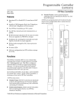
September 23, 1994
GFK-1040A
IMPORTANT PRODUCT INFORMATION
READ THIS INFORMATION FIRST
Product:
CPU State Logicr Module
IC697CSE784-JA*
This is the initial production release of the IC697CSE784 State Logic CPU module. The information in this Important
Product Information document covers the IC697 State Logic Operating System version 1.02.
* Note that the suffix was changed to add CSA and FM approval. No hardware or software changes were required.
Table 1. Catalog Numbers
New Catalog Number
Replaces
IC697CSE784-JA
IC697CSE784-HA
Identification
Hardware and software identification is summarized in the following tables.
Table 2. Hardware Identification
Catalog Number
Board
Identification
Board Revision
IC697CSE784-JA
CPHA2
44A729676-G01 R07 or later
Table 3. Software Identification
Catalog Number
IC697CSE784-JA
EPROM Location
EPROM/Diskette
Label
U72
U73
U74
U75
397-005C 5.00
397-006C 5.00
397-002E5.00
397-001E5.00
Function
not applicable
Update Information
Not applicable, since this is the initial version of the IC697CSE784 State Logic CPU module.
rState Logic is a registered trademark of Adatek, Inc.; tECLiPS is a trademark of Adatek, Inc.
2
Important Product Information
GFK-1040A
Documentation
The following table lists the applicable documentation for the IC697CSE784 State Logic CPU module.
Table 4. User Documentation
Catalog Number
Data Sheet
User Manual
IC697CSE784-JA
GFK-1035
see below
Read this document before installing or attempting to use the IC697CSE784 PLC CPU State Logic Module. For
more information, refer to the applicable State Logic Control System User’s Manual, Programmable Controller
Installation Manual, Programming Software User’s Manual, Programmable Controller Reference Manual, and
Important Product Information for the IC697CPU782 CPU.
Operating Notes
1. Storing a New Folder
Whenever the IC641 programming software program folder is stored from the programmer to
the controller (stop mode store), the State Logic program must also be downloaded again using
the ECLiPS program development software.
t
The reason that the State Logic program must be downloaded again is that the memory location
for the State Logic program changes according to the size of the IC641 programming software
program folder. Changes to the program folder may corrupt or invalidate the State Logic
program.
The State Logic CPU will not recognize State Logic Programs that were stored prior to storing
the IC641 programming software program folder.
Run mode store and on-line changes of ladder logic DO NOT require the State Logic program to
be downloaded.
2. Control Program Space
The memory space reserved for the control program is split into two sections. One section is
reserved for State Logic programs and the other section for programs entered with IC641
programming software, either Relay Ladder Logic and/or C block programs. There are about
156,000 bytes available for State Logic and about 60,000 bytes for Relay Ladder Logic and /or C
block programs.
3. System Status Bits
There are three %M status bits set by the State Logic operating system that can be accessed from
other system programs and devices. These bits are:
%M 1030 - Run Status Bit, set to 1 when the State Logic program is running.
%M 1031 - Digital Force Status Bit, set to 1 when a digital point is forced in State Logic.
%M 1032 - Analog Force Status Bit, set to 1 when an analog channel is forced in State Logic.
Important Product Information
3
GFK-1040A
The system status bits allow any device that is working at the IC641 programming software level
or SNP level to assess the current status of the State Logic CPU program. As an example a
program that is using Ladder Logic in addition to State Logic Programming could us %M1030 to
make sure that the Ladder program would halt execution if the State Logic program halts,
(%M1030 would be turned off).
4. Run-time Error Messages
Run-time error messages are filtered so that a stream of identical messages are not repeatedly
displayed filling up the display screen. When an error message is displayed, its contents are
stored so that another identical message is not displayed immediately. The stored message is
erased every minute on the minute so that if more errors occur, a new message is displayed
every minute, on the minute.
5. State Logic CPU Operational Lights
There are three LEDs on the State Logic CPU module which indicate the current state of the
CPU. The normal state of these LEDs when a State Logic Program is running in the CPU is ON.
The LEDs are off or flashing to indicate special or failure conditions.
Top LED - System OK
The top LED, labeled OK, is an indicator of the health of the CPU. It is ON when the CPU is
functioning properly. The LED blinks when the CPU executes the power-up diagnostics and
when the system has failed. The LED is OFF when the system has failed and the CPU cannot
communicate with the programmer.
Middle LED - Run
The second LED is an indicator of the run/stop status of the CPU. It is ON when the CPU is in
the RUN/ENABLE or RUN/DISABLE mode. The LED is OFF when the CPU is in STOP mode.
The CPU must be put into run mode using IC641 programming software. ECLiPS cannot
communicate with the State Logic CPU if the CPU is in STOP mode.
Bottom LED - Enabled
The bottom LED, labeled ENABLED indicates the state of the outputs. The LED is ON when the
outputs are enabled and the State Logic Program is running. The LED is OFF when the outputs
are disabled.
NOTE
The CPU will not go into RUN/ENABLED mode using IC641 programming software. Attempting to place the program into RUN/ENABLED mode from IC641
programming software will place the CPU into RUN/DISABLED mode. In order
to enter RUN/ENABLED mode the CPU must be loaded with a State Logic Program and the program must be running. ECLiPS programming software is used
to create, load, and run the State Logic Programs.
6. Run Enable/Disable Switch
A small switch is located beneath the operation LEDs on the State Logic CPU; the switch can be
used to control the Run Status of the CPU. The switch has positions that control the Run Status;
Up for Run/Enabled, Middle for Run/Disabled, and Down for Stop.
4
Important Product Information
GFK-1040A
The switch overrides the Run Status set by IC641 programming software or ECLiPS. If the
switch is moved to the down position, the State Logic program and any other programs in the
CPU stop execution and outputs are disabled. If the switch is then moved to the Run/Enabled
position the outputs become enabled, any ladder logic or C block programs begin execution, but
the State Logic program starts execution only if configured to run on power up.
If ladder logic and/or C block programs are used, it is possible to have the ladder logic or C block
program executing with the State Logic program halted. There are two ways to avoid this
condition:
1. Only use IC641 programming software and ECLiPS to set the run state of the programs.
2. Use the State Logic system status bits described above to control ladder logic or C block
program execution.
7. Reserved Memory Locations
Some %P memory locations are reserved for the State Logic Controller. The %P memory locations
reserved are in the range of 1 through 300. Do not use these %P memory locations in other programs.
8. Loading the State Engine Operating System with IC641 Programming Software
The IC697 State Logic System User’s Manual explains in Chapter 2 the procedure for loading the
State Engine Operating System into the CPU with IC641 programming software. The
description in the manual suggests loading the State Engine directly from the folder on the
floppy disk.
A better way to load the State Engine is to first use the IC641 programming software to copy the
folder called ENGINE from the floppy disk to the hard drive. Then follow the directions in the
manual to load the State Engine from the hard drive folder rather than from the floppy drive
folder.
The reason for this suggested procedure is that loading the State Engine from the folder on the
floppy drive is quite a bit slower than loading it from a folder on the hard drive. Loading the
State Engine from the floppy disk works properly, but is slower.
Restrictions and Open Problems
1. Automatic Program Execution
The State Logic program is normally halted when power is first applied to the system. Commands
from ECLiPS or OnTOP are used to start the State Logic program executing. The system can easily
be configured to start executing automatically when power is applied to the system.
To configure the system to start program execution on power up, select the System
Configuration option from the ECLiPS DEFINE menu. Select the CPU module configuration by
pressing the Enter key with the CPU module highlighted. To configure the system to execute
the State Logic program automatically when power is applied to the system, set the Run Program
at Power Up blank on the form to Y and press F9 to save the change.
Important Product Information
5
GFK-1040A
CAUTION
There is a remote possibility that retentive data in the controller can become corrupted during a power cycle. If there are any variables set to be retentive or any
Task is set to restart in the State that was last active using the Start_In_Last_State
keyword, the controller checks for that corruption possibility on power-up. If the
controller detects that there has been some corruption, the controller does not
start the program running, sends a message to be displayed by ECLiPS, and clears
all memory locations including any retentive memory locations.
If ECLiPS is not connected to the State Logic controller when data corruption is
detected, no other indication of the problem is displayed. To start the program
executing again, cycle the power using the power switch on the power supply.
The program starts executing with every Task starting in the Power-Up State.
If it is important that the program never power up with the program halted, do
not use the retentive option for any of the variables and do not set any Task to
start in the State that was last active. Ladder Logic programming should be
used to save data or to save the active States over a power cycle.
2. State Logic Processor and Serial Communications Module Compatibility
When using a State Logic Processor (SLP) together with a Serial Communication Module (SCM),
make sure that the SLP is not installed between the CPU and the SCM. Always install the SCM
in slots as close to the CPU as possible.
4. Get User Input Perform Function
This function is used to receive serial input. Any variable type may be used to store the input
received into the program. If the serial input data type is not valid for the variable type selected,
an error message is displayed and the program will continue to look for the correct type of data.
5. Communication Errors
In the unlikely event that a communications error occurs, ECLiPS displays an option to view
error codes. The error codes displayed are of two different types, major error code and minor error
code. The following table provides some more information on the meanings of these error codes.
To receive more information on this error contact technical support with the error number
displayed.
Major Code
01h
02h
03h
04h
Meaning
Slave doesn’t recognize Message type.
Slave doesn’t recognize Command.
Received a Type B Message without having previously received a type C Message.
General error, see Minor error code for details.
6
Important Product Information
GFK-1040A
Minor Code
01h
02h
03h
Meaning
07h
08h
09h
0Ah
0Bh
0Ch
0Dh
0Eh
0Fh
10h
11h
Tried to read from invalid variable type such as %R in DOS State Engine.
Tried to read from data that is outside the total number of the specified Variable.
Trying to write to invalid variable type such as %R in DOS State Engine or Digital I/O point in any
State Engine.
Trying to write data to a Variable that will exceed the total number of the specified Variable.
Trying to write more than an 80 character String value without a terminating ASCII Null.
Trying to Force an invalid variable type such as %R in DOS State Engine or an Integer variable in
any State Engine.
Trying to Force a Variable that will exceed the total number of the specified Variable.
Trying to force more than 32 variables of one type.
Not used
Trying to Clear a Force on a point that isn’t currently Forced.
Asking for Return of Forces when there are no Forced Variables.
Trying to Define in a Datagram an invalid variable type such as %R in DOS State Engine.
Trying to Define in a Datagram a Variable that will exceed the total number of the specified Variable.
Total data returned could exceed allowable maximum amount of data.
No data defined in Datagram.
Tried to change a non-existent Task.
Tried to change to a non-existent State.
30h
31h
32h
33h
No active messages at this time.
No active R term at this time.
No active Write_Buffer messages at this time.
No active Read_Buffer term at this time.
40h
41h
42h
43h
44h
49h
State Engine already in requested operating mode.
State Engine must be in Halt mode for this command.
Date or time asked for is invalid.
Trace Setup parameter is invalid.
Invalid Fault Clearing Parameters.
Invalid State Engine Control command.
60h
61h
62h
63h
64h
65h
66h
67h
68h
69h
6Ah
6Bh
6Ch
6Dh
6Eh
Download not allowed because controller is in Run mode.
Program too large for available memory.
Bad state for downloaded trace.
Download did not match the number of type P messages received.
Online Download not allowed because controller is in Halt mode.
Too many States for this Task
No Online Download Task waiting to be started.
Invalid active State number.
Received a message other than a P block during a download.
Function not supported by this State Engine.
Bad PSM detected in downloaded data.
Bad . type command (G. etc) in downloaded data.
Bad download for unknown reason.
Unknown error to Online Download Complete.
CSE924 memory protection key set.
04h
05h
06h
Problems Resolved by This Upgrade
Not applicable since this is a new module.