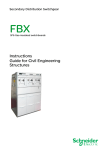
1
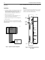
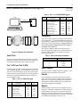
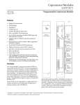
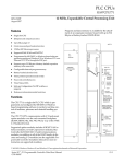
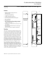
1
Communications Modules
IC697CMM712
56
GFK-1039B
August 1997
Serial Communications Module for State Logic CPU
Serial Communications Module for State Logic CPU (IC697CMM712)
datasheet GFK-1039B
Features
a47025
• Single slot Serial Communications for
State Logic CPU
• No programming required
OK
• CCM2 Protocol (slave only)
•
•
•
•
•
12 Mhz, 80C186 microprocessor
Two RS-422/RS-485 or RS-232 serial ports
Reset pushbutton
One Status LED
Soft Configuration (No dip switches or jumpers)
using IC641 (MS-DOS) programming software
configuration function
• Simultaneous communications on both ports at up
to 19.2 Kbaud
• Provides Serial Communications for State Logic
Control System
• All necessary memory supplied with module
Functions
The Serial Communications Module (SCM) provides
I/O ports for serial communications to the State Logic
Control System. The State Logic CPU control system
program uses the SCM to receive input from a serial
device and to transmit information to a serial device.
Each module provides two ports that may each be
configured to be RS-232 or RS-422/RS-485 ports. The
State Logic Control System supports up to four Serial
Communications Modules providing a capacity of a
total of eight serial ports. The Serial Communications
Modules are inserted in slots 2 through 5 of rack 0.
One of the eight ports may be a CCM2 port. An expanded form of the CCM2 protocol is supported providing read/write capability for analog input and output
values, %M internal flags, and current States of Tasks, in
addition to the normal discrete inputs and outputs, and
variable values. Additional functionality is provided for
custom CCM communication programs.
r MS-DOS is a registered trademark of Microsoft Corporation.
COMMUNICATIONS
COPROCESSOR
ÎÎ
ÎÎ
Î
ÎÎ
ÎÎ
Î
Î
ÎÎ
ÎÎ Î
Î
ÎÎ
ÎÎ
ÎÎ
Î
ÎÎ
Î
ÎÎ
Î
ÎÎ
Î
ÎÎ
Î
ÎÎ
Î
Î
ÎÎ
ÎÎÎ
Î
ÎÎ
Î
ÎÎ
Î
ÎÎ
Î
ÎÎ
Î
ÎÎ
Î
ÎÎ
Î
ÎÎ
Î
ÎÎ
Î
ÎÎ
Î
ÎÎ
Î
ÎÎ
Î
ÎÎ
Î
ÎÎ
Î
ÎÎ
Î
ÎÎ
Î
ÎÎ
Î
ÎÎ
Î
Î
ÎÎ
Î
Î
ÎÎ
Î
CMM 712
MODULE OK
ON = OK
PUSH TO RESTART
BATTERY
CONNECTIONS
INSTALL NEW
BATTERY BEFORE
UNPLUGGING OLD
BATTERY. USE
IC697ACC701
PORT 1
RS-232 OR
RS-422/485
COMPATIBLE
MODULE FUNCTION
SERIAL
COMMUNICA TIONS
FOR STATE LOGIC
CONTROL SYSTEM
PORT 2
RS-232 OR
RS-422/485
COMPATIBLE
MODULE
IC697CMM712
LABEL
44A726758-145R01
Communications Modules
2
GFK-1039B
August 1997
Serial Communications Module for State Logic CPU
Installation
Memor y
• Installation should not be attempted without referring to the applicable Programmable Controller
Installation Manual (see reference 3) and State Logic
Control System User’s Manual (see reference 1).
The Serial Communications Module does not require
a memory expansion daughter board. All necessary
memory is provided with the module.
• Make sure rack power is off.
a47026
• Connect the battery to either of the battery connectors on the module. (See Figure 2)
• Install in slots 2 through 5 of rack 0 (see Figure 1).
MODULE OK
STATUS
INDICATOR
• Turn on power.
The module should power up and blink the top LED.
When the diagnostics have completed successfully the
top LED stays on.
ÎÎ
ÎÎ
ÎÎ
ÎÎ
ÎÎ
Î
ÎÎ
ÎÎ
ÎÎ
ÎÎ
ÎÎ
ÎÎ
ÎÎ
ÎÎ
ÎÎ
Î
ÎÎ
ÎÎ
ÎÎ
ÎÎ
ÎÎ
ÎÎ
ÎÎ
ÎÎ
ÎÎ
Î
ÎÎ
ÎÎ
ÎÎ
ÎÎ
ÎÎ
ÎÎ
ÎÎ
ÎÎ
Î
ÎÎ
ÎÎ
ÎÎ
ÎÎ
ÎÎÎ
Î
ÎÎ
ÎÎ
ÎÎ
ÎÎ
ÎÎ
Î
ÎÎ
ÎÎ
ÎÎ
ÎÎ
ÎÎ
ÎÎ
ÎÎ
ÎÎ
ÎÎ
Î
ÎÎ
ÎÎ
ÎÎ
ÎÎ
ÎÎÎÎÎÎÎÎÎÎÎÎ
ÎÎÎÎÎÎÎ
RACK 0
P
S
OPEN
REPLACEMENT
BATTERY
CONNECTOR
CURRENTLY
INSTALLED
BATTERY
CONNECTOR
a47022
ÎÎ
ÎÎ
Î
ÎÎ
ÎÎ
Î
ÎÎ
ÎÎÎ
ÎÎ
Î
ÎÎ
ÎÎ
Î
ÎÎ
Î
ÎÎ
Î
ÎÎ
Î
ÎÎ
Î
ÎÎ
Î
Î
ÎÎ
ÎÎÎ
ÎÎ
Î
ÎÎ
Î
ÎÎ
Î
ÎÎ
Î
ÎÎ
Î
ÎÎ
Î
ÎÎ
Î
ÎÎ
Î
ÎÎ
Î
ÎÎ
Î
ÎÎ
Î
ÎÎ
Î
ÎÎ
Î
ÎÎ
Î
ÎÎ
Î
Î
ÎÎ
Î Î
CMM 712
MODULE OK
ON = OK
PUSH TO RESTART.
BATTERY
CONNECTIONS
C S S S S
P C C C C
U M M M M
INSTALL NEW
BATTERY BEFORE
UNPLUGGING OLD
BATTERY. USE
IC697ACC701
PORT 1
RS-232 OR
RS-422/485
COMPATIBLE
MODULE FUNCTION
SERIAL
COMMUNICATIONS
FOR STATE LOGIC
CONTROL SYSTEM
PORT 2
RS-232 OR
RS-422/485
COMPATIBLE
SERIAL
OR
CCM2
DEVICES
MODULE
IC697CMM712
LABEL
44A726758-145R01
CMM712
Figure 1. Typical PLC System Configuration
Figure 2. Serial Communications Module
User Details
Communications Modules
3
GFK-1039B
August 1997
Serial Communications Module for State Logic CPU
Î
Î
Î
a47023
PC-AT
SCM
IC690CBL702
RS-232
(DEFAULT PORT)
ÎÎÎÎÎÎÎÎÎ
ÎÎÎÎÎÎÎÎÎ
ÎÎÎÎÎÎÎÎÎ
PC-AT
9-PIN
MALE
ÎÎ
ÎÎ
ÎÎ
ÎÎÎ
Î
ÎÎÎÎ
Table 2. Port 1 or 2 RS-422/RS-485 Signals
4PL
PIN
PIN
DCD
1
RD
TD
DTR
RTS
CTS
GND
2
3
4
7
8
5
1
2
3
9-PIN
FEMALE
3PL
8
5
20
7
ÎÎ
ÎÎ
a42832
SHLD
TD
RD
DCD
CTS
DTR
GND
25-PIN
MALE
SCM
25-PIN
FEMALE
PIN
9
10
11
12
13
21
22
23
24
25
FUNCTION
Send Data (A)
Request to Send (A)
Clear to Send (A)
Termination for pin 13
Receive Data (A)
Send Data (B)
Request to Send (B)
Clear to Send (B)
Termination for pin 23
Receive Data (B)
Serial Ports
Output
Output
Input
Input
Output
Output
Input
Input
Configuration
There are no DIP switches or jumpers on this module
for configuration. Use the IC641 (MS-DOS) programming software configuration function to configure the
State Logic CPU for this module. Configure this module as catalog number IC697PCM711 with Configuration Mode set to PCM CFG.
Table 3. Slot to Port Number Correlation
Both ports are RS-232 and RS-422/RS-485 compatible.
Both ports acting simultaneously can each support up
to 19.2 Kbaud full duplex data communications.
SLOTNUMBER
PORT NUMBER
2
3
4
5
1 and 2
3 and 4
5 and 6
7 and 8
Port 1 (3PL) and Port 2 (4PL)
Connectors 3PL and 4PL contain signals for both RS-232
and RS-422/RS-485 types of communication circuits. The
pin-out for the RS-232 signals are per the RS-232 specification with an exception that pins not normally used for
RS-232 are used for RS-422/RS-485 signals. Details are
shown in tables 1 and 2.
Table 1. Port 1 or 2 RS-232 Signals
1
2
3
4
5
7
8
20
I/O
SD (A)
RTS (A)
CTS (A)
RD (A)
SD (B)
RST (B)
CTS (B)
RD (B)
The SCM is installed in slots 2 through 5 of rack 0.
The following table explains the correlation between
the slot number and the port number used in the
State Logic program.
Figure 3. Connection to PC Serial Port
PIN
SIGNAL
NAME
FUNCTION
Shield
Transmitted Data
Received Data
Request To Send
Clear To Send
Signal Ground
Data Carrier Detect
Data Terminal Ready
SIGNAL
NAME
TD
RD
RTS
CTS
0V
DCD
DTR
I/O
Output
Input
Output
Input
Input
Output
Status Indication
One Status LED is available as shown in Figure 2. This
LED indicates the condition of the module.
Controls
One pushbutton is provided. Push and hold for less
than 5 seconds to reset the module. Push and hold for
more than 5 seconds and the module factory default
configuration will be installed which may require the
State Logic program to be reloaded.
Batteries
A lithium battery (IC697ACC701) is installed as shown
in figure 2. This battery maintains serial port configuration information when power is removed. Be sure to
install the new battery before removing the old battery.
If during power-up diagnostics a low battery is detected
the Module OK LED (top) will not stay on.
Communications Modules
4
GFK-1039B
August 1997
Serial Communications Module for State Logic CPU
Table 4. References
Reference
1
2
3
Title
State Logic Control System User ’s Manual
Programmable Controller Reference Manual
Programmable Controller Installation Manual
Table 5. Specifications for IC697CMM712 [
[
Battery:
Shelf life
Memory retention
10 years at 20°C (68°F)
6 months nominal without applied power.
Serial Ports
RS-232/RS-422/RS-485 compatible
Current Required from +5 VDC Backplane Bus
0.7 amps
VME
System designed to support the VME standard C.1
Refer to GFK-0867B, or later for product standards and general specifications. For installations requiring compliance to more
stringent requirements (for example, European Union), refer to Installation requirements for Conformance to Standards.
Table 6. Ordering Information
Description
Serial Communications Module for State Logic, 12 Mhz, 20 Kbyte
Lithium Battery
Catalog Number
IC697CMM712
IC697ACC701
Note: For Conformal Coat option, or Low Temperature Testing option please consult the
factory for price and availability.