1
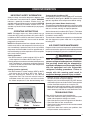
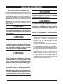
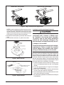
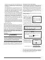
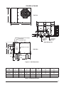
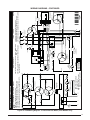
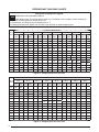
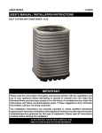
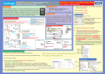
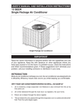
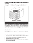
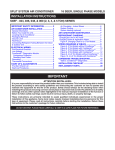
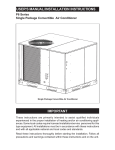
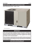
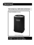
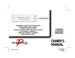
10 SEER P3RA SERIES USER’s MANUAL & INSTALLATION INSTRUCTIONS R-22 Single Package Air Conditioner IMPORTANT User, please read this information thoroughly and become familiar with the capabilities and use of your appliance before attempting to operate or maintain this unit. Keep this literature where you have easy access to it in the future. If a problem occurs, check the instructions and follow recommendations given. If these suggestions don’t eliminate your problem, call your servicing contractor. The Installation Instructions are primarily intended to assist qualified individuals experienced in the proper installation of this appliance. Some local codes require licensed installation/ service personnel for this type of equipment. Please read all instructions carefully before starting the installation. DO NOT DESTROY. PLEASE READ CAREFULLY AND KEEP IN A SAFE PLACE FOR FUTURE REFERENCE. USER INFORMATION Important Safety Information ....................................3 Operating Instructions ...............................................3 Cooling Operation .....................................................3 Heating Operation .....................................................3 Turning the Air Conditioner Off ..................................3 Operating the Indoor Blower Continuously ................3 Air Conditioner Maintenance.....................................3 Troubleshooting..........................................................3 WARRANTY INFORMATION A warranty certificate with full details is included with the Air Conditioner. Carefully review these responsibilities with your dealer or service company. The manufacturer will not be responsible for any costs found necessary to correct problems due to improper setup, improper installation, adjustments, improper operating procedure on the part of the user, etc. Some specific examples of service calls which are not included in the limited warranty are: • Correcting wiring problems in the electrical circuit supplying the Air Conditioner. • Resetting circuit breakers or other switches. • Adjusting or calibrating of thermostat. INSTALLER INFORMATION Important Safety Information ....................................4 General Information ................................................... 5 Before You Install this Unit ........................................5 Locating the Air Conditioner ....................................5 Minimum Clearance Requirements ......................... 5 Service Access Clearances .................................. 5 Clearances to Combustible Materials ...................5 Air Duct System .......................................................5 Air Conditioner Installation ....................................... 6 Unpacking the Unit ..................................................6 Installing Return & Supply Collars ............................6 Supply Duct ...........................................................6 Return Duct ...........................................................6 Connecting the Return & Supply Air Flexible Ducts ........................................................................ 6 Locating & Installing the Return Air Assembly.......... 6 Locating & Installing the Supply Dampers ................7 Condensate Drainage ..............................................8 Electrical Connections ............................................... 8 Pre - Electrical Checklist........................................... 8 Line Voltage .............................................................. 8 Overcurrent Protection ............................................. 9 Grounding ................................................................. 9 Unbalanced 3-Phase Supply Voltage ........................9 Thermostat / Low Voltage Connections .................. 10 Cooling Thermostat .............................................. 10 Heat/Cool Thermostat .......................................... 10 Blower Speed ......................................................... 10 Standard Motor (3, 4, & 5 Ton) ............................. 10 2 Startup & Adjustments ............................................ 11 Pre - Start Checklist................................................ 11 Installing Initial Refrigerant Charge ........................11 Start - Up Procedure .............................................. 11 System Cooling .................................................... 11 Short Cycle Protection ......................................... 11 Adjustment of Refrigerant Charge ..........................11 Charge Verification for R-22 Units in AC Mode w/ Outdoor Temperatures above 55° F ........................11 Air Conditioner Maintenance................................... 12 Component Functions ............................................. 12 High Pressure Switch ............................................. 12 Low Pressure Switch .............................................. 12 Replacement Parts ................................................... 12 Figures & Tables ....................................................... 13 Figure 11 - Unit Dimensions ................................ 13 Table 1 - P3RA Physical Data .............................. 13 Wiring Diagrams ..................................................... 14 Figure 12 - Single Phase - 3, 4, & 5 Ton .............. 14 Figure 13 - Three Phase - 5 Ton Only .................. 15 Refrigerant Charging Charts .................................. 16 Figure 14 - 3 Ton Units ......................................... 16 Figure 15 - 4 Ton Units ......................................... 16 Figure 16 - 5 Ton Units ......................................... 17 Blower Performance ............................................... 17 Table 2 - P3RA Airflow Data................................. 17 Installation / Performance Checklist ....................... 20 USER INFORMATION IMPORTANT SAFETY INFORMATION Safety markings are used to designate a degree or level of seriousness and should not be ignored. WARNING indicates a potentially hazardous situation that if not avoided, could result in personal injury or death. CAUTION indicates a potentially hazardous situation that if not avoided, may result in minor or moderate injury or property damage. OPERATING INSTRUCTIONS NOTE: Thermostat styles vary. Some models may not include the AUTO mode and others will have the AUTO in addition to HEAT and COOL selections. Please refer to the thermostat manufacturer’s User manual for detailed programming instructions. NOTE: If the temperature level is re-adjusted, or the system mode is reset, the fan and compressor in the unit may not start immediately. A protective timer circuit may hold the compressor and the outdoor fan off for approximately 5 minutes following a previous operation or the interruption of the main electrical power. Cooling Operation 1. Set the thermostat’s system mode to COOL or AUTO and change the fan mode to AUTO. See Figure 1. 2. Set the temperature selector to the desired temperature level.The outdoor fan, compressor, and blower motor will all cycle on and off to maintain the indoor temperature at the desired cooling level. Heating Operation (optional) 1. Set the thermostat’s system mode to HEAT or AUTO and change the fan mode to AUTO. See Figure 1. 2. Set the temperature selector to the desired temperature level. The furnace or electric heater kit and blower motor will cycle on and off to maintain the indoor temperature at the desired heating level. Turning the Air Conditioner OFF Change the thermostat’s system mode to OFF and the fan mode to AUTO (See Figure 1). NOTE: The system will not operate, regardless of the temperature selector setting. Operating the Indoor Blower Continuously The continuous indoor blower operation is typically used to circulate the indoor air to equalize a temperature unbalance due to a sun load, cooking, or fireplace operation. Set the thermostat fan mode to ON (Figure 1). The indoor blower starts immediately, and will run continually until the fan mode is reset to AUTO. The continuous indoor blower operation can be obtained with the thermostat system mode set in any position, including OFF. AIR CONDITIONER MAINTENANCE Proper maintenance is most important to achieve the best performance from the appliance and should be performed frequently at the beginning of each air conditioning season. WARNING: Your Air Conditioner contains liquid and gaseous refrigerant under pressure. Installation and servicing should only be attempted by qualified, trained personnel thoroughly familiar with the equipment and safe responsible refrigerant handling procedures. Failure to comply with this warning could result in equipment damage, personal injury, or death. • Keep the unit clean. Hose off periodically and keep unit fins clear of leaves and grass clippings. • Keep the unit clear of obstructions. DO NOT obstruct airflow with tall plants or shrubs. DO NOT store gasoline or other flammable materials on or near the unit. • Never operate the appliance without a filter installed in the return air duct. Inspect filters frequently and replace when necessary with filter of same dimensional size. TROUBLESHOOTING Fan Mode System Mode Temperature Selector Figure 1. Digital Thermostat If the unit fails to operate, check the following: • Check the thermostat setting. Make sure the system mode and temperature settings are correct. • Check the electrical panel for tripped circuit breakers. • Check the filters for dust accumulation. • Check the unit and make sure it is clean and not covered with grass or leaves. • If the items above don’t resolve your problems, then call your nearest service technician. 3 INSTALLER INFORMATION IMPORTANT SAFETY INFORMATION Please read all instructions before servicing this equipment. Pay attention to all safety warnings and any other special notes highlighted in the manual. Safety markings are used frequently throughout this manual to designate a degree or level of seriousness and should not be ignored. WARNING indicates a potentially hazardous situation that if not avoided, could result in personal injury or death. CAUTION indicates a potentially hazardous situation that if not avoided, may result in minor or moderate injury or property damage. WARNING: Shut off all electrical power to the unit before performing any maintenance or service on the system. Failure to comply may result in personal injury or death. WARNING: Unless noted otherwise in these instructions, only factory authorized parts or accessory kits may be used with this product. Improper installation, service, adjustment, or maintenance may cause explosion, fire, electrical shock or other hazardous conditions which may result in personal injury or property damage. WARNING: P3RA Single Package Air Conditioners leave the factory with a nitrogen holding charge. Follow all charging instructions for maximum unit performance and efficiency. Some local codes require licensed installation/service personnel to service this type of equipment. Refrigerant charging must be done by qualified personnel familiar with safe and environmentally responsible refrigerant handling procedures. Under no circumstances should the owner attempt to install and/or service this equipment. Failure to comply with this warning could result in property damage, personal injury, or death. 4 CAUTION: This unit uses refrigerant R-22. DO NOT use any other refrigerant in this unit. Use of another refrigerant will damage the unit. WARNING: The information listed below must be followed during the installation, service, and operation of this unit. Unqualified individuals should not attempt to interpret these instructions or install this equipment. Failure to follow safety recommendations could result in possible damage to the equipment, serious personal injury or death. • The installer must comply with all local codes and regulations which govern the installation of this type of equipment. Local codes and regulations take precedence over any recommendations contained in these instructions. Consult local codes for special installation requirements. • All electrical wiring must be completed in accordance with local, state and national codes and regulations. • This equipment contains nitrogen gas. Installation or servicing should only be performed by qualified trained personnel thoroughly familiar with this type equipment. • This unit is designed for outdoor installations only and should be located in a position as shown on page 5. • Follow all precautions in the literature, on tags, and on labels provided with the equipment. Read and thoroughly understand the instructions provided with the equipment prior to performing the installation and operational checkout of the equipment. The P3RA packaged air conditioner is designed only for outdoor ground level installations and can be readily connected to the high static duct system of a home.This unit has been tested for capacity and efficiency in accordance with A.R.I. Standards and will provide many years of safe and dependable comfort, providing it is properly installed and maintained. Abuse, improper use, and/or improper maintenance can shorten the life of the appliance and create unsafe hazards. To achieve optimum performance and minimize equipment failure, it is recommended that periodic maintenance be performed on this unit. The ability to properly perform maintenance on this equipment requires certain mechanical skills and tools. Before You Install this Unit The cooling load of the area to be conditioned must be calculated and a system of the proper capacity selected. It is recommended that the area to be conditioned be completely insulated and vapor sealed. Check the electrical supply and verify the power supply is adequate for unit operation. If there is any question concerning the power supply, contact the local power company. All units are securely packed at the time of shipment and upon arrival should be carefully inspected for damage prior to installing the equipment at the job site. Verify coil fins are straight. If necessary, comb fins to remove flattened or bent fins. Claims for damage (apparent or concealed) should be filed immediately with the carrier. Please consult your dealer for maintenance information and availability of maintenance contracts. Please read all instructions before installing the unit. Locating the Air Conditioner • Survey the job site to determine the best location for mounting the outdoor unit. Select a solid, level position, preferably on a concrete slab, slightly above the grade level, and parallel to the home. If possible, select a site for the unit that is as close as possible to the proposed return grille location. DO NOT PLACE UNIT UNDER THE HOME. • The unit should be located with consideration of minimizing the length of the supply and return ducts. If practical, place the air conditioner and its ducts in an area where they will be shaded from the afternoon sun, when the heat load is greatest. • The length of the supply and return ducts should be kept to a minimum with no sharp radius bends. • Overhead obstructions, poorly ventilated areas, and areas subject to accumulation of debris should be avoided. The hot condenser air must be discharged up and away from the home, and if possible, in a direction with the prevailing wind. Do not place the unit in a confined space. • Consideration should also be given to availability of electric power, service access, noise, and shade. Minimum Clearance Requirements Sufficient clearance for unobstructed airflow through the outdoor coil must be maintained in order to provide room for proper servicing and achieve rated performance. See Figure 2 for minimum clearances to obstructions. Service Access Clearances Blower access panel side .......................................... 24” Electrical compartment access panel side ............... 12” Clearance between overhang and top of unit ........ 72” Clearance around condenser coil area to wall or shrubs (excludes duct panel side) ............................. 12” Clearances to Combustible Materials Supply and return air ducts .........................................0” Duct connection side ...................................................0” 12" 24" TOP OF UNIT TO BE UNOBSTRUCTED GENERAL INFORMATION 12" 0" Figure 2. Minimum Unit Clearances Air Duct System Air ducts must be installed in accordance with local codes and regulations for air conditioning and ventilation standards. • The supply duct system, including the number and type of registers, will have much more effect on the performance of the system than any other factor. The duct must be sufficiently large to conduct an adequate amount of air to each register. See Figure 4 (page 7). • Duct work should be attached directly to the unit flanges for horizontal applications. • For highly resistive duct systems it may be necessary to add an additional return air duct and or supply to achieve maximum performance and prevent coil icing and refrigerant flood back • The air conditioning output of the system will not cool the home if air is lost to the outside through leaks in the duct system. Ducts that are collapsed or restricted by foreign objects will also prevent adequate air flow. 5 • All duct work passing through unconditioned space must be properly insulated to minimize duct losses and prevent condensation. Use insulation with an outer vapor barrier. Refer to local codes for insulation material requirements. AIR CONDITIONER INSTALLATION Unpacking the Unit It is recommended that the unit be unpacked at the installation site to minimize damage due to handling. CAUTION: Do not tip the unit on its side. Oil may enter the compressor cylinders and cause starting trouble. If unit has been set on its side, restore to upright position and do not run for several hours. Then run unit for a few seconds. Do this three or four times with five minutes between runs. 1. Remove the bands from around the unit. 2. Unfold the top and bottom cap flanges. 3. Carefully remove the top cap and tube. Installing Return & Supply Air Collars The supply and return fittings are included with the unit and located in the supply duct. They attach to the unit openings (Figure 3) with a flange and bead arrangement and may be secured with sheet metal screws. For easier access, install fittings before positioning unit in final location. See Figure 11 and Table 1 (page 13) for air opening sizes. Supply Duct 1. Position the supply duct collar so the edge of the unit opening fits between the flange and the bead. 2. Overlap the collar ends keeping the small screw holes underneath. 3. Align the holes in the crimped area and install one screw. Note: It may be necessary to loosen the four screws that hold the transition duct in order to install the supply fitting. Re-tighten when installation is complete. Duct Dimples Transition ws Duct Scre ir Supply A Return Duct 1. Align the slots with the holes in the collar and install two screws. 2. Position the collar over the opening and align the four holes in the collar with the four dimples or holes (depending on unit model) in the panel. 3. Using self-drilling screws (10-16x.5) attach the collar to the rear panel. Connecting the Return & Supply Air Flexible Ducts • The return duct collar for 3 ton models is 12” diameter and 14” for 4 & 5 ton models. • The supply duct collar for all models is 12” diameter. • Flexible ducts can be connected to the corresponding fittings with the clamps provided with the ducts. See Table 1. Note: To prevent a loss in cooling capacity, make sure all connections are tight. • The flexible ducts may be cut to the required length, see instructions packed with duct. Keep all ducts as short and straight as possible. Avoid sharp bends. • Ducts may be spliced with sheet metal sleeves and clamps. • After the inner duct is connected to the proper fitting, the insulation and plastic sleeve should be pulled over the connection and clamped. • Homes with multiple supply ducts (or special applications), a Y fitting is available to divide the supply air so it can be ducted to different areas of the home for more efficient cooling. Note: For maximum performance, insulate the Y fitting. Locating & Installing the Return Air Assembly To simplify installation, locate and install the return air assembly first. If desired, the return opening can be located inside a closet with louvered doors that has an open area equal to or greater than a 12” x 20” grille. The return air grille can be placed in the wall of a closet and the air ducted into the filter box through a boxed-in area at the closet floor level (Figure 5, page 7). Verify the filter is readily accessible. NOTE: The return air box with grille and filter should not be located in heavy traffic areas like hallways or center of rooms. A good spot is in a corner or under a table, if a minimum two inch clearance is available. ir Return A Figure 3. Return & Supply Air Collars 6 4. Tap collar (if necessary) to ensure engagement with unit opening and install second screw. 5. Tighten first screw and rotate collar clockwise so joint is near three o’clock position. 1. Start the installation from under the home by cutting a small hole in the subfloor. Determine how the floor joist location will affect cutting the opening needed for the return air box. NOTE: Floor joists are generally located on 16” centers, leaving 14-3/8” between joists. 2. After measuring the return air box (approximately 121/4” x 20-1/4”), cut the hole through the floor so that the box will fit between the floor joists. Care should be taken when cutting through carpeting to avoid snags. SINGLE DUCT APPLICATION MULTIPLE DUCT APPLICATION Figure 4. Single & Multiple Duct Applications NOTE: In most installations it will be necessary to cut a similar hole in the fiberboard directly under the hole in the floor. However, if the floor is more than ten inches deep, it will only be necessary to cut a hole for the collar on the return air box or for the insulated duct. 3. Set the box into the opening and fasten with screws or nails. 4. Install the filter and return air grille in the air box. Locating & Installing the Supply Damper(s) CAUTION: If installing this air conditioning system in conjunction with a furnace, a damper must be installed in the furnace base assembly to prevent cold air from being discharged around the heat exchanger. Damage to the heat exchanger and asphyxiation may occur if a damper is not installed. Check with the furnace manufacturer for damper requirements. Failure to install the required furnace damper may invalidate code agency listing and limited warranty on the furnace. Figure 5. Return Air Box Figure 6. Supply Damper When locating the supply damper(s), carefully check floor joists and frame members that could interfere with the installation of the damper or flexible duct. Ideally, the damper (Figure 6) should be located in the bottom of the main duct, forward of center of the home, at least three feet from the nearest register. The round supply opening in the slanted side of the damper should face the side of the home where the air conditioner is located. 1. Locate the center of the heat duct by cutting a small hole in the fiberboard below the duct at the desired location. 2. Cut a hole approximately 3/4” larger than the damper opening in the fiberboard. 3. Cut a 9-1/8” x 13-1/8” hole in the duct and bend over all tabs flat on the inside of the heat duct. 4. Insert the damper into the duct and bend over all tabs flat on the inside of the heat duct. 5. Seal the opening between the fiberboard and damper or flexible duct. 7 Condensate Drainage A 3/4” condensate fitting extends out of the side of the unit (Figure 3). The drain trap, shipped in the electrical compartment, must be installed to prevent water from collecting inside the unit. 1. Thread the elbow provided with the unit into the drain connection until hand tight. 2. Connect the condensate tubing onto the fitting, forming a trap near the drain connection. 3. Route the condensate tube from the trap to a suitable drain. NOTE: For proper drainage, make sure the trap is level to the ground and tubing outlet is below trap level. WARNING: To avoid risk of electrical shock, personal injury, or death, disconnect all electrical power to the unit before performing any maintenance or service. The unit may have more than one electrical supply. Label all wires prior to disconnection when servicing the unit. Wiring errors can cause improper and dangerous operation. • All electrical connections must be in compliance with all applicable local codes, ordinances, and current national codes. Elbow P-Trap Figure 7. Drain Trap Line Voltage Low Voltage Figure 8. Power Entry 8 ELECTRICAL CONNECTIONS Pre-Electrical Checklist Verify that the voltage, frequency, and phase of the supply source match the specifications on the unit rating plate. Verify that the service provided by the utility is sufficient to handle the additional load imposed by this equipment. Refer to the unit wiring label for proper high and low voltage wiring. Verify factory wiring is in accordance with the unit wiring diagram (Figures 12 or 13, pages 14 & 15). Inspect for loose connections. Phase balance on 3 phase units must always be checked. See Unbalanced 3-Phase Supply Voltage section (page 9). Line Voltage • A wiring diagram is located on the inside cover of the electrical box of the unit. The installer should become familiar with the wiring diagram before making any electrical connections to the unit. • An electrical disconnect must be located within sight of and readily accessible to the unit. This switch shall be capable of electrically de-energizing the unit. • Line voltage to the unit should be supplied from a dedicated branch circuit containing the correct fuse or circuit breaker for the unit. Incoming field wiring and minimum size of electrical conductors and circuit protection must be in compliance with information listed on the unit data label. Any other wiring methods must be acceptable to authority having jurisdiction. • Provide power supply for the unit in accordance with the unit wiring diagram, and the unit rating plate. Connect the line-voltage leads to the terminals on the contactor inside the control compartment. Extend leads through power wiring hole (Figure 8). Connect L1 & L2 directly to the contactor. For 3 phase models, connect L3 to the contactor. • The unit requires both power and control circuit electrical connections. Refer to the wiring diagram / schematic • • • • (Figures 12 & 13, pages 14 & 15)) for identification and location of unit field wiring interfaces. Make all electrical connections in accordance with all applicable codes and ordinances. Overcurrent protection must be provided at the branch circuit distribution panel and sized as shown on the unit rating label and according to applicable local codes. See the unit rating plate for minimum circuit ampacity and maximum overcurrent protection limits. Use only copper wire for the line voltage power supply to this unit. Use proper code agency listed conduit and a conduit connector for connecting the supply wires to the unit. Use of rain tight conduit is recommended. 208/230 Volt units are shipped from the factory wired for 230 volt operation. For 208V operation, remove the lead from the transformer terminal marked 240V and connect it to the terminal marked 208V. Optional equipment requiring connection to the power or control circuits must be wired in strict accordance of all applicable local codes, and the instructions provided with the equipment. Overcurrent Protection Generally, the best fuse or breaker for any air conditioner is the smallest size that will permit the equipment to run under normal usage and provide maximum equipment protection. Properly sized fuses and breakers also prevent nuisance trips during unit startup. If a fuse blows or a breaker trips, always determine the reason. Do not arbitrarily install a larger fuse or breaker and do not, in any case, exceed the maximum size listed on the data label of the unit. Grounding WARNING: The unit cabinet must have an uninterrupted or unbroken electrical ground to minimize personal injury if an electrical fault should occur. Do not use gas piping as an electrical ground! This unit must be electrically grounded in accordance with local codes or, in the absence of local codes, with the national codes. Ground the air conditioning unit using the green grounding screw provided in the control panel. Unbalanced 3-Phase Supply Voltage Voltage unbalance occurs when the voltages of all phases of a 3-phase power supply are no longer equal. This unbalance reduces motor efficiency and performance. Some underlying causes of voltage unbalance may include: Lack of symmetry in transmission lines, large single-phase loads, and unbalanced or overloaded transformers. A motor should never be operated when a phase imbalance in supply is greater than 2%. Perform the following steps to determine the percentage of voltage imbalance: 1. M e a s u r e t h e l i n e voltages of your 3 phase power supply where it enters the building and at a location that will only be dedicated to the unit installation (at the units circuit protection or disconnect). Example: AB = 226V BC = 230V AC = 227V 2. Determine the average voltage in the power supply. In this example, the measured line voltages were 226, 230, and 227. The average would be 228 volts (226 + 230 + 227 = 683 / 3 = 228). 3. Determine the maximum deviation: Example: From the values given in step 1, the BC voltage (230V) is the greatest difference in value from the average: Highest Value 230 - 228 = 2 228 - 226 = 2 228 - 227 = 1 4. Determine percent of voltage imbalance by using the results from steps 2 & 3 in the following equation. % Voltage Imbalance = 100 x Example: 100 x 2 = 0.88% 228 max voltage deviation from average voltage average voltage The amount of phase imbalance (0.88%) is satisfactory since the amount is lower than the maximum allowable 2%. Please contact your local electric utility company if your voltage imbalance is more than 2%. 9 Thermostat / Low Voltage Connections • The unit is designed to operate from a 24 VAC Class II control circuit.The control circuit wiring must comply with applicable local codes having jurisdiction. Thermostat connections should be made in accordance with the instructions supplied with the thermostat and the indoor equipment. • The low voltage wires must be properly connected. Route 24V control wires through the sealing grommet (Figure 8, page 8) near the power entrance. • Single stage thermostats can be used with this equipment. • The thermostat should be mounted about 5 feet above the floor on an inside wall. DO NOT install the thermostat on an outside wall or any other location where its operation may be adversely affected by radiant heat from fireplaces, sunlight, or lighting fixtures, and convective heat from warm air registers or electrical appliances. Refer to the thermostat manufacturer’s instruction sheet for detailed mounting information. Cooling Thermostat Connect the red & yellow wires from the unit to the R & Y terminals on the thermostat subbase. Connect the green wire to the yellow wire at the unit. See Figure 9. Heat/Cool Thermostat This unit requires the use of a single stage Heating/ Cooling thermostat. The heat/cool thermostat prevents simultaneous operation of the heating and cooling modes of operation and is equipped with an ON-AUTO fan mode that allows the home owner to operate the indoor blower when only air circulation is desired. Connect the red, yellow, green and brown low voltage wires to the R or RC, Y, G, & W terminals respectively on the thermostat base. The black wire is the 24 volt common required on some thermostats. See Figure 9. 4 Wire Heat/Cool Thermostat 2 Wire Cooling Thermostat R RED R Y YELLOW Y G GREEN GREEN W BROWN BROWN RED YELLOW ORANGE Single Stage Electric Heat R RED Y YELLOW G GREEN W BROWN ORANGE Control Wire Legend Green - Blower Relay Red - Transformer 24V Yellow - Cooling 1st Stage Brown - Heating 1st Stage Orange - Heating 2nd Stage Two Stage Electric Heat Optional Outdoor Thermostat (Field Supplied) Figure 9. Low Voltage Connections 10 If you have one thermostat for heating and another for cooling, they must be interlocked to prevent simultaneous operation. See Figure 10. 1. Turn the heating thermostat to its lowest possible setting. 2. If the cooling thermostat has an “On/Off” switch, turn it “On.” 3. Set the cooling thermostat to the desired temperature. 4. Turn the power on. Your air conditioner should start when room temperature exceeds the thermostat setting. Cooling Thermostat Furnace Thermostat R R Double Throw Double Pole Switch To Air Conditioner To Furnace Figure 10. Thermostat Interlock System Blower Speed For optimum system performance and comfort, it may be necessary to change the factory speed setting. WARNING: To avoid electric shock, personal injury, or death, turn off the electric power at the disconnect or the main service panel before making any electrical connections. Standard Motor (3, 4, & 5 Ton) 1. Disconnect all electrical power to the unit and remove the service panel. 2. Place the desired blower speed lead on the COM terminal. Use another wire tie (field supplied) to bundle the remaining motor leads. 3. Check all factory wiring as shown in the wiring diagram and inspect the connections to make sure none of them loosened during shipping or installation. START UP & ADJUSTMENTS Before You Start the Unit The following check list should be observed prior to starting the unit. Verify the unit is level and allows proper condensate drainage. Verify the outdoor coil and top of the unit are free from obstructions and debris, and all equipment access/ control panels are in place. Unit must be installed with the proper clearances as listed in Figure 2 (page 5). Verify that the duct work is sealed to prevent air leakage. Verify that the line voltage power leads are securely connected and the unit is properly grounded. Check the condenser fan to make sure it turns freely. Verify the thermostat is wired correctly and installed in a proper location. Make sure the low voltage wires are securely connected to the correct leads on the low voltage terminal strip. Verify that the power supply branch circuit overcurrent protection is sized properly. Installing Initial Refrigerant Charge IMPORTANT: Before you start unit, perform the following procedures to install the initial charge on units that are factory shipped with a nitrogen holding charge: 1. Read all installation instructions first. 2. Purge the nitrogen holding charge. 3. Evacuate the unit to 350 - 500 microns. 4. Allow the unit to remain under vacuum for at least 30 minutes. 5. Inspect the unit rating plate for the proper type of refrigerant and quantity. 6. Weigh in the proper amount of new (or reclaimed) refrigerant. Start-Up Procedure The control circuit may consist of an anti-short cycle timer that will not let the compressor re-start before 5 minutes have elapsed. 1. Set the system mode to OFF and the temperature mode to its highest setting. 2. Turn power on at the disconnect switch. 3. Set the system mode to ON or COOL. 4. Set the temperature mode below room temperature. Verify that the indoor blower, outdoor fan, and compressor energize and the cooling function starts. 5. Verify the discharge air grilles are adjusted and the system air is balanced. 6. Verify the duct work has no air leaks. 7. Verify the condensate drain is installed correctly and functions properly. 8. Set the temperature mode above room temperature. The unit should stop. 9. Instruct the homeowner on unit and thermostat operation and filter servicing. System Cooling Set the thermostat’s system mode to COOL and the fan mode to AUTO. Change the thermostat temperature selector below the existing room temperature. Allow the cooling system to operate for several minutes and check for the discharge of cool air at the supply registers. Verify HI and LO refrigerant pressures. FOR 3-Phase Models Only: If refrigerant pressures are abnormal and the compressor is rotating backwards, shut off main power to the unit and switch any two field wires at the disconnect. DO NOT alter unit wiring. Short Cycle Protection The control circuit may be equipped with a time-delay feature for protection against short cycling. With the system operating in the cooling mode, gradually raise the thermostat temperature setting until the whole system deenergizes. Immediately lower the thermostat temperature to the original setting and verify that the indoor blower is energized. After approximately 5 minutes the compressor and the outdoor fan will energize. Adjustment of Refrigerant Charge CAUTION: This air conditioner contains liquid and gaseous refrigerant under pressure. Adjustment of refrigerant charge should only be attempted by qualified, trained personnel thoroughly familiar with the equipment and safe responsible refrigerant handling procedures. Under no circumstances should the homeowner attempt to install and/or service this equipment. Failure to comply with this warning could result in equipment damage, personal injury, or death. • To achieve rated capacity and efficiency the compressor must run for a minimum of 12 hours. • The refrigerant charge can be checked and adjusted through the service ports provided external to the unit. Use only gage line sets which have a “Schrader” depression device present to actuate the valve. Charge Verification for R-22 Units in AC Mode with Outdoor Temperatures Above 55° F 1. With the system operating at steady-state, measure the discharge refrigerant pressure in psig at the service valve. 2. Measure the suction refrigerant pressure (psig) at the service valve. 3. Determine the appropriate charge from the charts (Figures 14 - 16, pages 16 - 17) for the discharge temperature measured. 11 COMPONENT FUNCTIONS AIR CONDITIONER MAINTENANCE WARNING: To prevent electrical shock, personal injury, or death, disconnect all electrical power to the unit before performing any maintenance or service. The unit may have more than one electrical supply. Proper maintenance is important to achieve optimum performance from the air conditioner.The ability to properly perform maintenance on this equipment requires certain mechanical skills and tools. If you do not possess these skills, contact your dealer for maintenance. Consult your local dealer about the availability of maintenance contracts. Routine maintenance should include the following: • Inspect and clean or replace air filters at the beginning of each heating and cooling season, or more frequently if required. • Inspect the condensate drain and outdoor coil at the beginning of each cooling season. Remove any debris. Clean the outdoor coil and louvers as necessary using a mild detergent and water. Rinse thoroughly with water. • Inspect the electrical connections for tightness at the beginning of each heating and cooling season. Service as necessary. High Pressure Switch (HPS) - Optional A high-pressure switch may be installed and located in the liquid line internal to the unit. The switch is designed to protect the system when very high pressures occur during abnormal conditions. Under normal conditions, the switch is closed. If the liquid pressure rises above 425 psig, the switch will open and de-energize the unit. The switch will close again once the liquid pressure decreases to 360 psig. Please note that the switch interrupts the thermostat inputs to the unit. When the switch opens and then closes, there may be a 5 minute short cycling delay before the unit will energize. Low Pressure Switch (LPS) - Optional A low-pressure switch may be installed and located in the suction line internal to the unit. The switch is designed to protect the compressor from a loss of charge. Under normal conditions, the switch is closed. If the suction pressure falls below 5 psig, the switch will open and deenergize the unit. The switch will close again once the suction pressure increases above 20 psig. Please note that the switch interrupts the thermostat inputs to the unit. When the switch opens and then closes, there may be a 5 minute short cycling delay before the unit will energize. REPLACEMENT PARTS Replacement parts are available through all Nordyne distributors. Please have the complete model and serial number of the unit when ordering replacement parts. ELECTRICAL: Capacitors Temperature Limit Switches Compressors Thermostats Contactors Time Delay Relays Pressure Switches Transformers Relays CAUTION: The unit should never be operated without a filter in the return air system. Replace disposable filters with the same type and size. • Do not attempt to add additional oil to motors unequipped with oil tubes. The compressor is hermetically sealed at the factory and does not require lubrication. 12 MOTORS: Blower Motor Fan Motor COMPONENTS: Blower Assembly Fan Grille Cabinet Panels Filter/Driers FIGURES & TABLES W Top View A 5.5 3.0 B L 9.15 1" 3.15 9.04 Electric Heater Power Supply Power Supply 17.50 12" diameter Supply Duct Opening Low Voltage Supply 14" diameter Return Duct Opening Back (Duct) View H 17.86 15.36 Control Access Panel Blower Access Panel Side View 10.10 1" 3/4" NPT Drain Connection 1.38 3.2 18.01 3.2 5.29 12.13 Figure 11. Unit Dimensions Model No. P3RA- Length -L- Width W Height -H- -A- -B- Return Diameter (in) Supply Diameter (in) 036KA 49 35 22.2 35.02 2.48 12 12 048KA 49 35 30.2 35.02 2.48 14 12 060KA 49 35 30.2 35.02 2.48 14 12 060CA 49 35 30.2 35.02 2.48 14 12 Table 1. P3RA Physical Data 13 4 6 3 AMP FUSE L2 T2 COMPRESSOR RCB N.O. R R G G Logic C Y C C RCB COM RELAY CONTROL BOARD CC1 5 RCB N.C. CAPACITOR L S S W2 SEE NOTE 5 9 7 TRANSFORMER SEE NOTE 6 F Figure 12. P3RA - Single Phase with PSC Motor - 3, 4, & 5 Ton Models C T1 CC 3 1 208/230 Volt L1 C BLACK FIELD WIRING LOW VOLTAGE HIGH VOLTAGE LEGEND: R S RED YELLOW BLUE ORANGE BLACK CONTACTOR On Units with no Pressure Switch a Yellow Wire connects Y to CC C RED BLACK BROWN BROWN GREEN YE/BK STRIPE LOW PRESS SW BLACK WHITE N.O. N.C. COM (SELECT MODELS) YE/BK STRIPE G R XFMR-R OUTDOOR FAN MOTOR YELLOW HIGH PRESS SW (SELECT MODELS) YELLOW YELLOW TRANSFORMER SEE NOTE 6 COM 208 240 24V RED XFMR-C SPEED UP RELAY CONTROL BOARD CAPACITOR 1-Phase Supply Voltage 5. Two speed motor lead connections: Black - High (default) Red - Low 6. For 208V operation remove white wire from 230V tap and place on 208V tap. - Indicates plug connection Number indicates pin location RCB - Relay Control Board CC - Contactor Coil 1 HIGH LOW PRESS SW PRESS SW (SELECT MODELS) 2 24V COM 208 240 R H C DUAL CAPACITOR BLOWER MOTOR R FAN MOTOR H S LINE VOLTAGE NOTES: 1. Disconnect all power before servicing. 2. For supply connections use copper conductors only. 3. Not suitable on systems that exceed 150V to ground. 4. For replacement wires use conductors suitable for for 105° C. Small Packaged Air Conditioner C YELLOW T1 H H Y G R WHITE W2 R S C 0310 7110860 ¢711086-¤ RED RED Jumper Plug must be in place if no electric heat is applied COMPRESSOR BK/WH STRIPE YE/BK STRIPE WHITE ORANGE BROWN RED WHITE SEE NOTE 5 RED 9 Pin Plug for Heater Kit connection GRAY YELLOW BLUE BLOWER MOTOR C To Thermostat RED L S Circuit Breaker (optional) Ground Screw DUAL CAPACITOR F T2 L1 FUSE L2 L1 L2 60Hz 1. Couper le courant avant de faire letretien. 2. Employez uniquement des conducteurs en cuivre. 3. Ne convient pas aux installations de plus de 150V a la terre. Single Phase 1 2 3 4 5 6 7 8 9 14 1 2 3 4 5 6 7 8 9 WIRING DIAGRAM WIRING DIAGRAMS 3 AMP FUSE L3 4 6 CC2 CC3 5 T2 T3 RCB N.O. RCB N.C. CAPACITOR R R G G Logic C Y RELAY CONTROL BOARD L2 C T3 L W2 C F CAPACITOR 7 TRANSFORMER SEE NOTE 6 T1 9 CC CC1 3 1 208/230 Volt L1 C BLACK FIELD WIRING LOW VOLTAGE HIGH VOLTAGE LEGEND: R S RED YELLOW BLUE ORANGE BLACK CONTACTOR On Units with no Pressure Switch a Yellow Wire connects Y to CC C RED BLACK BROWN BROWN GREEN YE/BK STRIPE LOW PRESS SW BLACK WHITE N.O. N.C. COM (SELECT MODELS) YE/BK STRIPE G R XFMR-R OUTDOOR FAN MOTOR YELLOW HIGH PRESS SW (SELECT MODELS) YELLOW YELLOW TRANSFORMER SEE NOTE 6 COM 208 240 24V RED XFMR-C SPEED UP RELAY CONTROL BOARD CAPACITOR L3 3-Phase Supply Voltage 5. Two speed motor lead connections: Black - High (default) Red - Low 6. For 208V operation remove white wire from 230V tap and place on 208V tap. - Indicates plug connection Number indicates pin location RCB - Relay Control Board CC - Contactor Coil 1 T1 SEE NOTE 5 COMPRESSOR BLOWER MOTOR HIGH LOW PRESS SW PRESS SW (SELECT MODELS) 2 24V COM 208 240 R S FAN MOTOR T2 RCB COM H S LINE VOLTAGE NOTES: 1. Disconnect all power before servicing. 2. For supply connections use copper conductors only. 3. Not suitable on systems that exceed 150V to ground. 4. For replacement wires use conductors suitable for for 105° C. 60Hz T3 L3 FUSE L2 Y L S R W2 WHITE ORANGE BROWN RED T1 RED T2 0310 7110900 ¢711090u¤ BK/WH STRIPE T3 COMPRESSOR Jumper Plug must be in place if no electric heat is applied RED WHITE SEE NOTE 5 RED 9 Pin Plug for Heater Kit connection WHITE GRAY YELLOW BLUE C YE/BK STRIPE BLOWER MOTOR To Thermostat G H RED CAPACITOR Ground Screw Circuit Breaker (optional) YELLOW T2 T1 L2 L1 L1 1. Couper le courant avant de faire letretien. 2. Employez uniquement des conducteurs en cuivre. 3. Ne convient pas aux installations de plus de 150V a la terre. Three Phase 1 2 3 4 5 6 7 8 9 Small Packaged Air Conditioner 1 2 3 4 5 6 7 8 9 WIRING DIAGRAM WIRING DIAGRAMS - CONTINUED Figure 13. P3RA Wiring Diagram - 3 Phase with PSC Motor (5 Ton Models Only) 15 REFRIGERANT CHARGING CHARTS Refrigerant Charging Chart Legend: Shaded boxes indicate flooded conditions. Rated design values. The suction pressure will vary from design value if outdoor air flow, entering dry bulb, or entering wet bulb temperatures vary. 1. All pressures are listed psig and all temperatures in °F 2. Discharge temperatures greater than charted values indicate an undercharged system. OUTDOOR TEMPERATURE Suct. Press. 70° F 75° F 80° F 85° F 90° F 95° F 100° F 105° F Dis. Dis. Dis. Dis. Dis. Dis. Dis. Dis. Dis. Dis. Dis. Dis. Dis. Dis. Dis. Dis. Press. Temp. Press. Temp. Press. Temp. Press. Temp. Press. Temp. Press. Temp. Press. Temp. Press. Temp. 67 192 159 69 194 165 208 163 71 196 170 210 168 224 167 73 198 175 212 173 226 172 239 171 75 202 178 214 178 228 177 242 175 255 174 179 271 178 273 182 287 231 181 244 180 257 234 184 247 184 260 183 81 250 188 263 187 275 186 289 185 303 185 83 254 191 266 191 279 190 291 189 305 188 270 195 282 194 295 194 307 192 286 199 298 198 311 197 302 202 314 201 318 206 77 218 181 79 85 87 89 181 91 93 Figure 14. Charging Chart for 3 Ton Units OUTDOOR TEMPERATURE Suct. Press. 70° F 75° F 80° F 85° F 90° F 95° F 69 205 160 71 207 165 222 105° F 165 73 210 170 224 170 238 170 75 211 177 226 175 240 175 255 175 77 215 180 228 181 242 180 257 180 271 180 185 287 185 289 189 304 245 185 259 185 273 248 188 261 189 275 189 83 265 192 278 193 291 193 306 194 320 194 85 268 196 282 197 295 197 308 198 322 198 285 201 298 202 312 202 324 202 302 206 315 206 328 207 318 211 332 211 335 216 79 81 87 89 231 184 91 93 95 Figure 15. Charging Chart for 4 Ton Units 16 100° F Dis. Dis. Dis. Dis. Dis. Dis. Dis. Dis. Dis. Dis. Dis. Dis. Dis. Dis. Dis. Dis. Press. Temp. Press. Temp. Press. Temp. Press. Temp. Press. Temp. Press. Temp. Press. Temp. Press. Temp. 190 REFRIGERANT CHARGING CHARTS - CONTINUED OUTDOOR TEMPERATURE Suct. Press. 70° F 75° F 80° F 85° F 90° F 95° F 100° F 105° F Dis. Dis. Dis. Dis. Dis. Dis. Dis. Dis. Dis. Dis. Dis. Dis. Dis. Dis. Dis. Dis. Press. Temp. Press. Temp. Press. Temp. Press. Temp. Press. Temp. Press. Temp. Press. Temp. Press. Temp. 62 208 161 64 211 166 226 167 172 66 213 172 228 243 173 68 70 72 74 76 78 80 82 84 86 88 214 218 179 182 230 177 245 178 232 235 183 186 248 182 250 253 188 191 261 263 178 183 265 188 267 271 274 192 196 199 278 280 184 188 282 193 285 288 292 197 201 205 295 297 189 193 299 198 303 306 309 202 206 210 312 314 194 198 316 202 320 324 327 207 211 215 330 332 199 203 333 207 338 341 345 212 216 221 Figure 16. Charging Chart for 5 Ton Units BLOWER PERFORMANCE Model Number P3RA 036KA 048KA 060KA 060CA External Static Pressure (in. WC)1 0.1 0.2 0.3 0.4 0.5 0.6 High 1480 1440 1390 1330 1270 1190 Low 1270 1230 1190 1140 1080 1000 High 1840 1780 1730 1650 1580 1500 Low 1700 1650 1590 1540 1470 1390 High 1800 1740 1680 1620 1540 1470 Low 1660 1610 1560 1500 1430 1360 High 1800 1740 1680 1620 1540 1470 Low 1660 1610 1560 1500 1430 1360 1 Based on 230 Volt operation, dry coil, and no filters. NOTE: Blower performance data shown above 0.30” WC external static pressure(ESP) is for reference only. Maximum allowable external static pressure with electric heat added to unit is 0.30” WC. Table 2. P3RA Airflow Data 17 18 19 INSTALLATION / PERFORMANCE CHECK LIST REFRIGERATION SYSTEM: INSTALLATION ADDRESS: Was unit given 24 hr warm up period for crankcase heaters (if installed)? CITY ________________________ YES NO STATE ________________ UNIT MODEL # ________________________________________ Stage-1 Liquid Pressure (high side) ________________________ UNIT SERIAL # ________________________________________ Stage-1 Suction Pressure (low side) ________________________ Unit Installed Minimum clearances per Figure 2 (page 5)? Has the owner’s information been reviewed with the customer? YES NO Has the Literature Package been left with the unit? YES NO YES NO INSTALLER NAME: CITY _______________________ STATE ________________ INSTALLER ELECTRICAL SYSTEM: Electrical connections tight? YES NO Line voltage polarity correct? YES NO Has the thermostat been calibrated? YES NO Is the thermostat level? YES NO Is the heat anticipator setting correct? (If Applicable) YES NO PLEASE LEAVE THESE INSTALLATION INSTRUCTIONS WITH THE HOMEOWNER. This section for 3-Phase models only Rated Voltage: ______________________________________ VOLTS L1-L2 Volts: ________________________________________ VOLTS L1-L3 Volts: ________________________________________ VOLTS L2-L3 Volts: ________________________________________ VOLTS Avg. Volts: _________________________________________ VOLTS Max. deviation of voltage from avg. volts:______________________________________ VOLTS % Volt imbalance: ___________________________________ VOLTS ¢709180#¤ O’ Fallon, MO 7091800 7091800 (Replaces 7085580) Specifications & illustrations subject to change without notice or incurring obligations. Printed in U.S.A. (04/10)