1
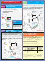
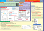
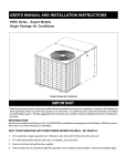
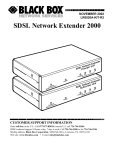
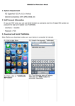
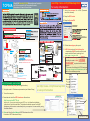
TCP54A
iProx RFID Embedded TCP/IP Ethernet Access Controller
for 5,000 users and 50,000 Transaction Records
Dimensions: 101mm x 71mm x 32mm
see http://avea.cc/tcp54asetup.html
for setup information
www.av ea.cc
7. Setup the password for LOGIN (Password
cannot be reversed)
8. Setup the RFID reader
9. Setup the System PIN
10. Define the workgroup for reports
11. ADD Cards and enter Card Information
- download and SAVE the add card file (serial
number with the ID card’s packing) from
http://avea.cc/serialno.html
12. Goto the Access Manager , click “PUT” to
put setting to reader & click “UPLOAD
TO READER” to upload card information
to reader
*** Please see User Manual of NET Attendance
http://avea.cc/spec/net%20attendance.pdf for
details of Access Manager setup.
DATA TO SLAVE (TD to KS232S’ RJ45 socket - PIN4)
DATA FROM SLAVE (RD to KS232S’ RJ45 socket - PIN5)
GROUND (G to KS232S’RJ45 socket - PIN3)
no t
in use
CR1220 battery for clock
(Battery not included)
RE LAY TERMINAL
- ma x i mu m r a t ing 2A / 2 4 Vdc
or 2A / 120Va c
( T O E LECT RI C STR I KE)
10
8
NET ATTENDANCE - QUICK START
1. Connect cables and power (see Wiring Instruction)
see http://avea.cc/tcp54asetup.html
2. Setup the reader’s IP address and parameters (see Reader Setup)
for setup information
12
9
3. Turn on the computer.
User Manual
Installation Manual of
NET Attendance from Start
4.Download and install the NET Attendance software from
http://avea.cc/sw/NETTA.zip
Unzip the file - Execute the installer program NETTA.msi. Just f ollow the installation
instruction to finish the installation . The detailed installation manual for the NET
Attendance will be installed automatically into your computer. You can read it by using
the Adobe Reader.
NET Attendance
User Manual
NET Attendance
6
11
7
5. Print and follow the User Manual of NET Attendance from Start
For details of NET Attendance's Setup.
Ref: tcp54a\20110808
FOUR MODES OF OPERATION - Wiring Instruction
Access
Control
(Single
reader
- outside
premises)
IN Mode : Access
Control
(Single
reader
- outside
the the
premises)
IN
for Entrance
with
- forMode
Entrance- with
or without
PINor without PIN
In this mode, the TCP54A
unit is installed
is installed
outside
outside
the premises.
the premises.
1. connect an electric strike to the RELAY TERMINAL
2. connect Ethernet to the RJ45 socket
3. Connect the POWER
3
22
3
G N D ( P o w e r sup ply n e g at iv e t e rm in al)
DC I N ( P ow e r s u pply positive t er mina)
ET H ERNET
CABL E
DATA TO SLAVE (TD to KS232S’ RJ45 socket - PIN4)
DATA FROM SLAVE (RD to KS232S’ RJ45 socket - PIN5)
GROUND (G to KS232S’RJ45 socket - PIN3)
OPEN
1NORMAL
COMMON
CR1220 battery for clock
(Battery not included)
(P OWE R 9 - 1 2 V 5 0 0mA )
(TO P O W E R)
1
NORMAL CLOSE
3
Bypass
switch
Power
ETHERNE T
CA B L E
1
CLOCK Mode :
as
Time Clock/
CLOCK
Mode : Time Recorder
Time Clock
/ Time
Recorder
- as
access
control
feature
is disabled
Electric
strike
-
RELAY TERMINAL
- maximum rating 2A/24Vdc
or 2A/120Vac
- connect power to the POWER TERMINAL
- connect Ethernet to the RJ45 socket
RELAY TER M INAL
(TO EL E CT R IC S T RIK E )
2
OUT Mode + Access Control (Dual readers)
TCP54A as MASTER for exit + KS232S as SLAVE for entrance
Slave
(Optional)
(BYPA S S SWI T CH)
5
RJ45
Socket
- access control feature is disabled
not
in us e
Access Control (Dual readers)
TCP54A as MASTER for entrance + KS232S as SLAVE for exit
-
In this mode, the unit is installed outside the premises as the master. A
KS232S is installed inside the premises as the slave unit. An electric
strike and a bypass switch are connected to the slave and are installed
inside the premises. Pressing the bypass switch or presenting the
authorized cards will release the strike.
4
PO W ER TERMINAL
(TO POWER 9 -12V 500mA)
RJ45
Socket
IN Mode +
Slave
+
4
I N3 PIN
N5
t o PD ” t o t o PI
”
“
“ T “ RD ” P I N 6
to
“+”
TCP54A r eader
PIN1
PIN2
PIN3
PIN4
PIN5
PIN6
PIN7
PIN8
K S2 32 S sla ve r e a de r
* * * R emove al l j u m p ers o n sla v e
-
In this mode, the unit is installed inside the premises as the master. A
KS232S is installed outside the premises as the slave unit. An electric
strike is connected to the master inside the premises. Authorized cards
will release the strike. The controller’s states and card information can
be uploaded by the NET Attendance software through the ethernet
network.
RJ45
Socket
4
3
E THERNE T
CABL E
POWER TE R MIN A L
(TO P OW E R 9-12V 500mA )
DC IN
GND
SLAVE T E RMINAL
(RD to PIN5)
DATA FROM SLAVE
DATA TO SLAVE
(TD to PIN4)
1
2
T C P54A read er
“ -” to PI N 3
“T D ” to PIN4
“RD” to PIN 5
"+"t o PI N 6
PIN1
PIN2
PIN3
PIN4
PIN5
PIN6
PIN7
PIN8
REL AY TER M I N AL
- m aximu m r at i ng 2 A /24Vd c or 2A/120Vac
(TO ELECT R IC STRIKE)
KS2 3 2S slave reader
* * * Remov e all jumpers o n s l ave
TCP54A READER SETUP
To enter configuration mode : hold the '*' key while applying the power
to the reader. 'CONF' will be shown on the reader. Place an ID card
over the reader will register a 'MASTER' card to configuration later
without power off the reader. By presenting the 'MASTER card to the
reader, it will enter the configuration mode directly.
Press ' ' to cycle the parameters to be configured:
*
Parameter
IP
Gate
Net
Port
Description
IP address of the reader itself
Gateway IP address
Netmask
Port number
Default
192.168.1.234
192.168.1.1
255.255.255.0
1668
To edit the parameter, press '#' key. '.' is entered by pressing '#' key,
i.e. use enter 192.168.1.123, the key sequence is 192#168#1#123,
then press '#' key to confirm entry or '*' key to cancel the operation.