1
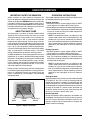
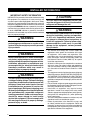
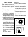
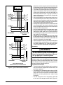
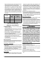
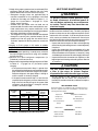
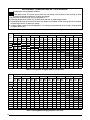
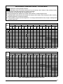
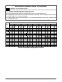
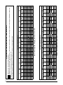
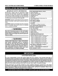
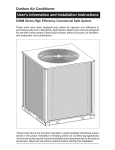
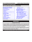
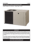
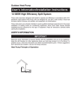
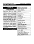
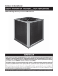
Split system HEAT PUMP
R-22, 13 SEER
User’s Manual / Installation Instructions
User Information
Important Safety Information.................. 3
About the Heat Pump...................................... 3
Operating Instructions................................ 3
Cooling Operation.................................................. 3
Heating Operation.................................................. 3
Emergency Heat.................................................... 3
Defrost Operation................................................... 3
Operating the Heat Pump for Automatic
Cooling & Heating.................................................. 4
Operating the Indoor Blower Continuously............ 4
Turning the Heat Pump Off.................................... 4
Heat Pump Maintenance................................ 4
Troubleshooting............................................ 4
Installer Information
Important Safety Information.................. 5
Heat Pump Installation................................. 6
General Information............................................... 6
Before You Install this Unit...................................... 6
Locating the Heat Pump........................................ 6
Packaging Removal............................................... 6
Ground Level.......................................................... 6
Connecting Refrigerant Tubing between the
Indoor & Outdoor Unit............................................ 7
Electrical Wiring............................................ 7
Pre - Electrical Checklist........................................ 7
Line Voltage............................................................ 7
Grounding.............................................................. 8
Thermostat Connections........................................ 8
Startup & Adjustments................................ 9
Pre - Start Checklist............................................... 9
Start-up Procedures............................................... 9
Air Circulation - Indoor Blower............................. 9
System Cooling.................................................... 9
System Heating.................................................... 9
Refrigerant Charging.................................. 9
Charging R-22 Units in AC Mode with
Outdoor Temperatures Above 55° F..................... 10
Heat Pump Maintenance.............................. 10
Replacement Parts....................................... 10
Figures & Tables............................................ 11
Figure 4. Unit Dimensions ............................... 11
Refrigerant Charging Charts................................ 11
Figure 5. Charging Chart for 1.5 Ton Units....... 11
Figure 6. Charging Chart for 2 Ton Units ......... 12
Figure 7. Charging Chart for 2.5 Ton Units ...... 12
Figure 8. Charging Chart for 3 Ton Units ......... 13
Figure 9. Charging Chart for 3.5 Ton Units....... 13
Figure 10. Charging Chart for 4 Ton Units........ 14
Figure 11. Charging Chart for 5 Ton Units........ 14
Refrigerant Charging Tables - Cooling Mode....... 15
Table 4. Charging Table for 1.5 Ton Units......... 15
Table 5. Charging Table for 2 Ton Units............ 15
Table 6. Charging Table for 2.5 Ton Units......... 16
Table 7. Charging Table for 3 Ton Units............ 16
Table 8. Charging Table for 3.5 Ton Units......... 17
Table 9. Charging Table for 4 Ton Units............ 17
Table 10. Charging Table for 5 Ton Units.......... 18
Refrigerant Charging Tables - Heating Mode....... 19
Table 11. Charging Table for 1.5 Ton Units....... 19
Table 12. Charging Table for 2 Ton Units.......... 19
Table 13. Charging Table for 2.5 Ton Units....... 20
Table 14. Charging Table for 3 Ton Units.......... 20
Table 15. Charging Table for 3.5 Ton Units....... 21
Table 16. Charging Table for 4 Ton Units.......... 21
Table 17. Charging Table for 5 Ton Units.......... 22
Electrical Information........................................... 23
Figure 12. Wiring Diagram................................ 23
Table 18. Electrical Specs & Physical Data...... 24
INSTALL. / PERFORMANCE CHECKLIST.......... 24
IMPORTANT
Please read this information thoroughly and become familiar with the capabilities and use of your appliance
before attempting to operate or maintain this unit. Keep this literature where you have easy access to
it in the future. If a problem occurs, check the instructions and follow recommendations given. If these
suggestions don’t eliminate the problem, call your servicing contractor.
The Installation Instructions are primarily intended to assist qualified individuals experienced in the proper
installation of this appliance. Some local codes require licensed installation/service personnel for this
type of equipment. Please read all instructions carefully before starting the installation.
DO NOT DESTROY. PLEASE READ CAREFULLY AND
KEEP IN A SAFE PLACE FOR FUTURE REFERENCE.
USER INFORMATION
important SAFETY INFORMATION
Operating Instructions
Safety markings are used frequently throughout this
manual to designate a degree or level of seriousness and
should not be ignored. WARNING indicates a potentially
hazardous situation that if not avoided, could result in
personal injury or death. CAUTION indicates a potentially
hazardous situation that if not avoided, may result in minor
or moderate injury or property damage.
Please refer to the thermostat manufacturer’s User manual
for detailed programming instructions.
About the Heat Pump
Your heat pump is a unique, all weather comfort-control
appliance that will heat and cool your home year round
and provide energy saving comfort. It’s an unknown fact
that heat is always in the air, even when the outside
temperature is below freezing. The heat pump uses this
basic law of physics to provide energy saving heat during
the winter months. For example, If the outdoor temperature
is 47° F (8° C), your heat pump can deliver approximately
3.5 units of heat energy per each unit of electrical energy
used, as compared to a maximum of only 1 unit of heat
energy produced with conventional heating systems.
In colder temperatures, the heat pump performs like an air
conditioner run in reverse. Available heat energy outside
the home is absorbed by the refrigerant and exhausted
inside the home. This efficient process means you only
pay for “moving” the heat from the outdoors to the indoor
area. You do not pay to generate the heat, as is the case
with more traditional furnace designs.
During summer, the heat pump reverses the flow of the
heat-absorbing refrigerant to become an energy-efficient,
central air conditioner. Excess heat energy inside the
home is absorbed by the refrigerant and exhausted
outside the home.
Fan
Mode
System
Mode
Temperature
Selector
Figure 1. Digital Thermostat
2
Cooling Operation
1.Set the thermostat’s system mode to COOL or AUTO
and change the fan mode to AUTO. See Figure 1
2.Set the temperature selector to the desired temperature
level.The outdoor fan, compressor, and blower motor will
all cycle on and off to maintain the indoor temperature
at the desired cooling level.
NOTE: If the temperature level is re-adjusted, or the
system mode is reset, the fan and compressor in the
outdoor unit may not start immediately. A protective
timer circuit holds the compressor and the outdoor fan
off for approximately 5 minutes following a previous
operation or the interruption of the main electrical
power.
Heating Operation
1.Set the thermostat’s system mode to HEAT or AUTO
and change the fan mode to AUTO. See Figure 1.
2.Set the temperature selector to the desired temperature
level. The compressor, outdoor fan, and blower motor
will cycle on and off to maintain the indoor temperature
at the desired heating level.
NOTE: If the temperature level is re-adjusted, or the
system mode is reset, the fan and compressor in the
outdoor unit may not start immediately. A protective
timer circuit holds the compressor and the outdoor fan
off for approximately 5 minutes following a previous
operation or the interruption of the main electrical
power.
Emergency Heat
Some thermostats may include a system mode called EM
HT or AUX HT, etc. This is a back-up heating mode that
should only be used if a problem is suspected. With the
mode set to EM HT, etc., the compressor and outdoor fan
will be locked off and supplemental heat (electric resistance
heating) will be used as a source of heat. Sustained use
of electric resistance heat in place of the heat pump will
result in an increase in electric utility costs.
Defrost Operation
During cold weather heating operation, the outdoor unit
will develop a coating of snow and ice on the heat transfer
coil. This is normal and the unit will defrost itself. This unit
monitors ambient and coil temperatures to regulate the
defrost function accordingly.
USER INFORMATION
At the beginning of the defrost cycle, both the outdoor
condenser fan and compressor will turn off. After
approximately 30 seconds, the compressor will turn on
and begin to heat the outdoor coil causing the ice and
snow to melt.
NOTE: While the ice and snow is melting, some steam
may rise from the outdoor unit as the warm coil causes the
melting frost to evaporate. When defrost is completed, the
outdoor fan motor will start, and the compressor will turn
off again. In approximately 30 seconds the compressor
will start up again and continue normal operation.
Operating the Heat Pump for Automatic Cooling
and Heating
1.Set the thermostat system switch to AUTO and the
thermostat fan switch to AUTO. See Figure 1.
NOTE: Thermostat styles vary. Some models will
not include the AUTO mode and others will have the
AUTO in place of the HEAT and COOL. Others may
include all three. Refer to the instructions supplied
with your thermostat for specific instructions.
2.Set the thermostat temperature to the desired
temperature level.The outdoor unit and the indoor blower
will then cycle on and off in either the heating or cooling
mode of operation as required to automatically maintain
the indoor temperature within the desired limits.
Operating the Indoor Blower Continuously
The continuous indoor blower operation is typically used to
circulate the indoor air to equalize a temperature unbalance
due to a sun load, cooking, or fireplace operation.
Set the thermostat fan mode to ON (Figure 1). The indoor
blower starts immediately, and will run continually until
the fan mode is reset to AUTO.
The continuous indoor blower operation can be obtained
with the thermostat system mode set in any position,
including OFF.
Turning the Heat Pump Off
Change the thermostat’s system mode to OFF and the fan
mode to AUTO. See Figure 1. NOTE: The system will not
operate, regardless of the temperature selector setting.
HEAT PUMP MAINTENANCE
CAUTION:
Shut off all electrical power to the unit before
performing any maintenance. Failure to comply
may result in personal injury or death.
Proper maintenance is most important to achieve the best
performance from the appliance and should be performed
by a qualified service technician at least once a year. Read
the maintenance items below and follow the instructions
for years of safe, trouble free operation.
Regular Cleaning
WARNING:
Do not place combustible material on or against
the unit cabinet. Do not place combustible
materials, including gasoline and any other
flammable vapors and liquids, in the vicinity
of the unit.
• Clean or replace the indoor air filter at the start of each
heating and cooling season, and when an accumulation
of dust and dirt is visible on the air filter.
• Remove any leaves and grass clippings from around
the coil of the outdoor unit, being careful not to damage
the aluminum fins.
• Check and remove any obstructions, such as twigs,
sticks, etc.
TROUBLESHOOTING
If the unit fails to operate, check the following:
• The thermostat is properly set. See Cooling Operation
for air conditioning or Heating Operation for furnace.
• The unit disconnect fuses are in good condition and
the electrical power to the unit is turned on.
Warranty Information
A warranty certificate with full details is included with the
Heat Pump. Carefully review these responsibilities with
your dealer or service company. The manufacturer will not
be responsible for any costs found necessary to correct
problems due to improper setup, improper installation,
adjustments, improper operating procedure on the part
of the user, etc. Some specific examples of service calls
which are not included in the limited warranty are:
• Correcting wiring problems in the electrical circuit
supplying the Heat Pump.
• Resetting circuit breakers or other switches.
• Adjusting or calibrating of thermostat.
3
INSTALLER INFORMATION
important SAFETY INFORMATION
INSTALLER: Please read all instructions before servicing
this equipment. Pay attention to all safety warnings and
any other special notes highlighted in the manual. Safety
markings are used frequently throughout this manual to
designate a degree or level of seriousness and should not
be ignored. WARNING indicates a potentially hazardous
situation that if not avoided, could result in personal injury
or death. CAUTION indicates a potentially hazardous
situation that if not avoided, may result in minor or moderate
injury or property damage.
WARNING:
Shut off all electrical power to the unit before
performing any maintenance or service on the
system. Failure to comply may result in personal
injury or death.
WARNING:
Unless noted otherwise in these instructions,
only factory authorized parts or accessory kits
may be used with this product. Improper service,
installation, adjustment, or maintenance may
cause explosion, fire, electrical shock or other
hazardous conditions which may result in
personal injury or property damage.
WARNING:
This split system heat pump left the factory with
a nitrogen holding charge. Follow all charging
instructions for maximum unit performance and
efficiency. Some local codes require licensed
installation/service personnel to service this
type of equipment. Refrigerant charging must
be done by qualified personnel familiar with safe
and environmentally responsible refrigerant
handling procedures. Under no circumstances
should the owner attempt to install and/or
service this equipment. Failure to comply with
this warning could result in property damage,
personal injury, or death.
4
CAUTION:
This unit uses R-22 refrigerant. DO NOT use
any other refrigerant in this unit. Use of another
refrigerant will damage the unit.
WARNING:
The information listed below must be followed
during the installation, service, and operation
of this unit. Unqualified individuals should
not attempt to interpret these instructions or
install this equipment. Failure to follow safety
recommendations could result in possible
damage to the equipment, serious personal
injury or death.
• The installer must comply with all local codes and
regulations which govern the installation of this type
of equipment. Local codes and regulations take
precedence over any recommendations contained in
these instructions. Consult local building codes and
the National Electrical Code (ANSI CI) for special
installation requirements.
• All electrical wiring must be completed in accordance
with local, state and national codes and regulations
and with the National Electric Code (ANSI/NFPA 70)
or in Canada the Canadian Electric Code Part 1 CSA
C.22.1.
• This equipment contains liquid and gaseous refrigerant
under high pressure. DO NOT USE ANY PORTION OF
THE CHARGE FOR PURGING OR LEAK TESTING.
Installation or servicing should only be performed by
qualified trained personnel thoroughly familiar with this
type equipment.
• Fully annealed, refrigerant grade copper tubing should
be used when installing the system. Refrigerant suction
line tubing should be fully insulated.
• Installation of equipment may require brazing
operations. Installer must comply with safety codes
and wear appropriate safety equipment (safety glasses,
work gloves, fire extinguisher, etc.) when performing
brazing operations.
• This unit is designed for outdoor installations only and
should be located as descibed on page 5.
• Follow all precautions in the literature, on tags, and
on labels provided with the equipment. Read and
thoroughly understand the instructions provided with
the equipment prior to performing the installation and
operational checkout of the equipment.
Heat Pump INSTallATION
General Information
This split system heat pump is designed only for outdoor
rooftop or ground level installations. The unit has been
tested for capacity and efficiency in accordance with
AHRI Standards and will provide many years of safe
and dependable comfort, providing it is properly installed
and maintained. Abuse, improper use, and/or improper
maintenance can shorten the life of the appliance and
create unsafe hazards.
To achieve optimum performance and minimize equipment
failure, it is recommended that periodic maintenance be
performed on this unit. The ability to properly perform
maintenance on this equipment requires certain
mechanical skills and tools.
Before You Install this Unit
√ The cooling load of the area to be conditioned must be
calculated and a system of the proper capacity selected.
It is recommended that the area to be conditioned be
completely insulated and vapor sealed.
√ Check the electrical supply and verify the power supply
is adequate for unit operation.The system must be wired
and provided with circuit protection in accordance with
local building codes. If there is any question concerning
the power supply, contact the local power company.
√ The indoor section (air handler, furnace, etc) should be
installed before routing the refrigerant tubing. Refer to
the indoor unit's installation instructions for installation
details.
√ All units are securely packed at the time of shipment and
upon arrival should be carefully inspected for damage
prior to installing the equipment at the job site. Verify
coil fins are straight. If necessary, comb fins to remove
flattened or bent fins. Claims for damage (apparent or
concealed) should be filed immediately with the carrier.
√ Please consult your dealer for maintenance information
and availability of maintenance contracts. Please read
all instructions before installing the unit.
Locating the Heat Pump
• Survey the job site to determine the best location for
mounting the outdoor unit. See Figure 4 (page 10) for
unit dimensions.
• Overhead obstructions (Figure 2), poorly ventilated
areas, and areas subject to accumulation of debris
should be avoided.
• Sufficient clearance for unobstructed airflow through the
outdoor coil must be maintained in order to achieve rated
performance. See Figure 2 for minimum clearances to
obstructions.
• Consideration should be given to availability of electric
power, service access, noise, and shade.
Packaging Removal
NOTE: To prevent damage to the tubing connections,
carefully remove the carton and user’s manual from the
equipment. Discard the shipping carton.
Ground Level
Ground level installations must be located according to
local building codes or ordinances and these requirements:
• Clearances must be in accordance with those shown
in Figure 2.
• A suitable mounting pad must be provided and separate
from the building foundation. The pad must be level
and strong enough to support the weight of the unit.
The slab height must be a minimum of 2” (5 cm) above
grade and with adequate drainage. See Figure 2.
Roof Mount
• The method of mounting should be designed so that it
does not overload roof structures or transmit noise to
the interior of the structure. The roof must be structurally
capable of handling the weight of the unit.
• Full perimeter support is required under the unit.
Support must be made of weather resistant materials
and installed prior to unit installation.
• The support must be built to raise the unit 6" above
the roof.
6” from Building
or Structure
24" for
Service Access
12" or 18”
See Note
12" or 18”
See Note
DO NOT
OBSTRUCT
TOP OF UNIT
NOTE: Units require full perimeter clearances. Installer must maintain
18” between two units or 12” between single unit and structure.
48”
2” Mounting Pad
Figure 2. Clearance Requirements
5
Connecting Refrigerant Tubing Between the Indoor
& Outdoor Unit
CAUTION:
This system uses R-22 refrigerant which may
contain POE oil. When servicing, cover or seal
openings to minimize the exposure of the refrigerant system to air to prevent accumulation
of moisture and other contaminants. See page
9 for additional info.
After outdoor and indoor unit placement has been
determined, route refrigerant tubing between the
equipment in accordance with sound installation practices.
• When connecting refrigerant linesets together, it is
recommended that dry nitrogen be flowing through
the joints during brazing to prevent internal oxidation
and scaling.
• Refrigerant tubing should be routed in a manner that
minimizes the length of tubing and the number of bends
in the tubing. If precise forming of refrigerant lines is
required, a copper tubing bender is recommended.
Avoid sharp bends and contact of the refrigerant lines
with metal surfaces.
• Refrigerant tubing should be supported in a manner
that the tubing will not vibrate or abrade during system
operation.
• Tubing should be kept clean of foreign debris during
installation.
• Every effort should be made by the installer to ensure
that the field installed refrigerant containing components
of the system have been installed in accordance with
these instructions and sound installation practices to
insure reliable system operation and longevity.
• The maximum recommended interconnecting
refrigerant line lengths is 75 ft. and the vertical elevation
difference between the indoor and outdoor sections
should not exceed 20 ft.
COPPER WIRE SIZE — AWG
(1% Voltage Drop)
200
Supply Wire Length-Feet
150
100
50
Supply Circuit
Ampacity
6
4
8
6
10
8
14
12
15
20
4
6
8
10
25
4
4
6
10
30
3
4
6
8
35
3
4
6
8
40
2
3
4
6
45
2
3
4
6
50
2
1
3
2
4
3
6
4
55
60
Wire Size based on N.E.C. for 60° type copper conductors.
Table 1. Copper Wire Size
6
• To maintain the unit's warranty, it is required that a
filter drier be installed when the system is open to
the atmosphere. This includes, but is not limited to,
replacing the evaporator and/or condenser of a system.
The filter drier must be installed in strict accordance
with the manufacturer’s installation instructions.
• Optional equipment such as liquid line solenoid
valves, low ambient, etc., should be installed in
strict accordance with the manufacturer’s installation
instructions.
ELECTRICAL WIRING
WARNING:
To avoid risk of electrical shock, personal
injury, or death, disconnect all electrical power
to the unit before performing any maintenance
or service. The unit may have more than one
electrical supply.
Label all wires prior to disconnection when
servicing the unit. Wiring errors can cause
improper and dangerous operation.
• All electrical connections must be in compliance with
all applicable local codes and ordinances, and with
the current revision of the National Electric Code
(ANSI/NFPA 70).
• For Canadian installations the electrical connections
and grounding shall comply with the current Canadian
Electrical Code (CSA C22.1 and/or local codes).
Pre-Electrical Checklist
√ Verify that the voltage, frequency, and phase of the
supply source match the specifications on the unit
rating plate. See Table 18 (page 24).
√ Verify that the service provided by the utility is sufficient
to handle the additional load imposed by this equipment.
Refer to the unit wiring label for proper voltage wiring.
√ Verify factory wiring is in accordance with the unit
wiring diagram or Figure 12 (page 22). Inspect for
loose connections.
Line Voltage
• A wiring diagram is located on the inside cover of the
electrical box of the outdoor unit. The installer should
become familiar with the wiring diagram before making
any electrical connections to the outdoor unit.
• An electrical disconnect must be located within
sight of and readily accessible to the unit. This
switch shall be capable of electrically de-energizing
the outdoor unit.
• Line voltage to the unit should be supplied from a
dedicated branch circuit containing the correct fuse
or circuit breaker for the unit. Incoming field wiring
and minimum size of electrical conductors and circuit
Thermostat
G R W 2C E O Y
Green
G
Red
R
White
W
•
E
R
•
W2
C O Y
•
Black
C
•
Air Handler
Heat Pump OD
Section
Typical Heat Pump with
Outdoor Thermostat
and Air Handler
Thermostat
G R W 2C E O Y
Green
G
Red
R
•
E
R
White
W
W2
C O Y
Black
Grounding
WARNING:
The unit cabinet must have an uninterrupted or
unbroken electrical ground to minimize personal
injury if an electrical fault should occur. Do not
use gas piping as an electrical ground!
C
Air Handler
•
protection must be in compliance with information listed
on the outdoor unit data label. Any other wiring methods
must be acceptable to authority having jurisdiction.
The outdoor unit requires both power and control circuit
electrical connections. Refer to the wiring diagram /
schematic for identification and location of outdoor unit
field wiring interfaces Figure 12 (page 22). Make all
electrical connections in accordance with all applicable
codes and ordinances.
Overcurrent protection must be provided at the branch
circuit distribution panel and sized as shown on the unit
rating label and according to applicable local codes.
See the unit rating plate for minimum circuit ampacity
and maximum overcurrent protection limits.
Provide power supply for the unit in accordance with the
unit wiring diagram, and the unit rating plate. Connect
the line-voltage leads to the terminals on the contactor
inside the control compartment.
Use only copper wire for the line voltage power supply
to this unit as listed in Table 1 (page 6). Use proper
code agency listed conduit and a conduit connector
for connecting the supply wires to the unit. Use of rain
tight conduit is recommended.
208/230 Volt units are shipped from the factory wired
for 230 volt operation. For 208V operation, remove the
lead from the transformer terminal marked 240V and
connect it to the terminal marked 208V.
Optional equipment requiring connection to the power
or control circuits must be wired in strict accordance
of the NEC (ANSI/NFPA 70), applicable local codes,
and the instructions provided with the equipment.
Heat Pump OD
Section
Typical Heat Pump with
Outdoor Thermostat and Air Handler
Figure 3. Typical Thermostat Connections
This unit must be electrically grounded in accordance
with local codes or, in the absence of local codes, with
the National Electrical Code (ANSI/NFPA 70) or the CSA
C22.1 Electrical Code. Use the grounding lug provided in
the control box for grounding the unit.
Thermostat Connections
• Thermostat connections should be made in accordance
with the instructions supplied with the thermostat and
the indoor equipment.
• The outdoor unit is designed to operate from a 24 VAC
Class II control circuit. The control circuit wiring must
comply with the current provisions of the NEC (ANSI/
NFPA 70) and with applicable local codes having
jurisdiction.
• The low voltage wires must be properly connected
to the units low voltage terminal block (Figure 3).
7
Recommended wire gauge and wire lengths for typical
thermostat connections are listed in Table 2.
• The thermostat should be mounted about 5 feet
above the floor on an inside wall. DO NOT install the
thermostat on an outside wall or any other location
where its operation may be adversely affected by radiant
heat from fireplaces, sunlight, or lighting fixtures, and
convective heat from warm air registers or electrical
appliances. Refer to the thermostat manufacturer’s
instruction sheet for detailed mounting and installation
information.
Thermostat
Wire Gauge
Recommended T-Stat Wire
Unit to T-Stat (Length in FT)
2-Wire
(Heating)
5-Wire
(Heating/Cooling)
24
55
25
22
90
45
20
140
70
18
225
110
Table 2. Thermostat Wire Gauge
START UP & ADJUSTMENTS
Pre-Start Check List
√ Verify the indoor unit is level and allows proper
condensate drainage.
√ Verify the outdoor coil and top of the unit are free from
obstructions and debris, and all equipment access/
control panels are in place.
√ Verify air filters are cleaned and properly installed.
√ Verify duct work is sealed to prevent air leakage.
√ Verify line voltage power leads are securely connected
and the unit is properly grounded.
√ Verify low voltage wires are securely connected to the
correct leads on the low voltage terminal strip.
√ Verify power supply branch circuit overcurrent protection
is sized properly.
√ Verify the thermostat is wired correctly.
Start-Up Procedures
The thermostat's function mode should be set to OFF and
the fan mode should be set to AUTO. Close all electrical
disconnects to energize the system.
Air Circulation - Indoor Blower
1.Set the thermostat system mode on OFF and the fan
mode to ON.
2.Verify the blower runs continuously. Check the air delivery
at the supply registers and adjust register openings for
balanced air distribution. If insufficient air is detected,
examine ductwork for leaks or obstructions.
3.Set the thermostat fan mode to AUTO and verify the
blower stops running.
System Cooling
1.Set the thermostat’s system mode to COOL and the
fan mode to AUTO. Gradually lower the thermostat
8
temperature setpoint below room temperature and
verify the outdoor unit and indoor blower energize.
2.Verify blower wheel is spinning in direction indicated by
arrow. Feel the air being circulated by the indoor blower
and verify that it is cooler than ambient temperature.
Listen for any unusual noises. If unusual sounds occur,
determine the source of the noise and correct as
necessary.
3.Verify HI and LO refrigerant pressures.
4.Allow the system to operate for several minutes and then
set the temperature selector above room temperature.
Verify the fan and compressor cycle off with the
thermostat. NOTE: The blower should also stop unless
fan mode is set to the ON position.
System Heating (optional)
1.Set the thermostat's system mode to HEAT and the
temperature mode above room temperature.
2.Verify the optional heating equipment (furnace or
electric heat) and indoor blower energize. Feel the air
being circulated by the indoor blower and verify that
it is warmer than ambient temperature. Listen for any
unusual noises. If unusual sounds occur, determine the
source of the noise and correct as necessary.
Refrigerant Charging
WARNING:
This split system heat pump left the factory
with a nitrogen holding charge. DO NOT
operate any unit while it contains a Nitrogen
holding charge. Doing so may damage the
units compressor. Follow these charging
instructions for maximum unit performance and
efficiency. Some local codes require licensed
installation/service personnel to service this
type of equipment. Refrigerant charging must
be done by qualified personnel familiar with safe
and environmentally responsible refrigerant
handling procedures. Under no circumstances
should the owner attempt to install and/or
service this equipment. Failure to comply with
this warning could result in property damage,
personal injury, or death.
To properly charge these units:
1.Read all Installation Instructions first.
2.Complete any brazing operations. (e.g. Split system
line-sets)
3.Leak check and evacuate the whole system using proper
methods.
4.Purge the nitrogen holding charge.
5.Evacuate the unit to 350-500 microns.
6.Allow the unit to remain under vacuum for at least 30
min.
7.Weigh-In the proper amount of new (or reclaimed) R-22
refrigerant. Refer to Table 3 below or the units rating
label to determine the correct amount of charge.
• Refrigerant charging charts are applicable only to
matched assemblies of this equipment and listed
airflows for the indoor coil. Refer to Figures 5 - 11
(pages 10 - 13) and Tables 4 - 10 (pages 14 - 17) for
correct system charging.
• Outdoor units with indoor coils not listed are not
recommended. Deviations from rated airflows or nonlisted combinations may require modification to the
expansion device and refrigerant charging procedures
for proper and efficient system operation.
• The refrigerant charge can be checked and adjusted
through the service ports provided external to the
outdoor unit. Use only gage line sets which have a
“Schrader” depression device present to actuate the
valve.
Charging an R-22 system in AC mode at outdoor
temperatures above 55° F for optimized sub-cooling of
10° F - 12° F.
1.With the system operating at steady-state, measure
the liquid refrigerant pressure (in psig) at the outdoor
unit service valve.
2.Measure the liquid refrigerant temperature (in
Fahrenheit) at the service valve.
3.Determine the required liquid refrigerant pressure. Refer
to Tables 11 - 17 (pages 18 - 21) for correct system
charging.
•If the pressure measured in Step 1 is greater than
the required liquid refrigerant pressure determined in
Step 3, then there is too much charge in the system.
Remove refrigerant and repeat Steps 1 through 3
until the system is correctly charged.
•If the pressure measured in Step 1 is less than the
required liquid refrigerant pressure determined in
Step 3, there is too little charge in the system. Add
refrigerant and repeat Steps 1 through 3 until the
system is correctly charged.
Restrictor Bore Size
(inches)
Indoor
Outdoor
System
Charge
R2 (oz.)
1.5 Ton
0.053
0.041
93
2 Ton
0.061
0.047
96
Unit Size
(Ton)
2.5 Ton
0.069
0.049
144
3 Ton
0.078
0.057
155
3.5 Ton
0.083
0.059
248
4 Ton
0.090
0.065
248
5 Ton
0.101
0.071
268
Table 3. 13 SEER Split System Heat Pump Orifice
Heat Pump MAINTENANCE
WARNING:
To prevent electrical shock, personal injury,
or death, disconnect all electrical power to
the unit before performing any maintenance
or service. The unit may have more than one
electrical supply.
Proper maintenance is important to achieve optimum
performance from the Heat Pump. The ability to properly
perform maintenance on this equipment requires certain
mechanical skills and tools. If you do not possess these
skills, contact your dealer for maintenance. Consult your
local dealer about the availability of maintenance contracts.
Routine maintenance should include the following:
• Inspect and clean or replace air filters at the beginning
of each heating and cooling season, or more frequently
if required.
• Inspect the condensate drain and outdoor coil at the
beginning of each cooling season. Remove any debris.
Clean the outdoor coil and louvers as necessary using
a mild detergent and water. Rinse thoroughly with water.
• Inspect the electrical connections for tightness at the
beginning of each heating and cooling season. Service
as necessary.
CAUTION:
The unit should never be operated without
a filter in the return air system. Replace
disposable filters with the same type and size.
• Do not attempt to add additional oil to motors
unequipped with oil tubes. The compressor is
hermetically sealed at the factory and does not require
lubrication.
REPLACEMENT PARTS
Replacement parts are available through your distributor. Please
have the complete model and serial number of the unit when
ordering replacement parts.
ELECTRICAL:
Capacitors
Temperature Limit Switches
Compressors
Thermostats
Contactors
Time Delay Relays
Pressure Switches
Transformers
Relays
MOTORS:
Blower Motor
Fan Motor
COMPONENTS:
Blower Assembly
Fan Grille
Cabinet Panels
Filter/Driers
Expansion Valves
9
FIGURES & TABLES
D
W
H
*Picture is representative only, may not be exact match
Unit Size (Ton)
Height -H-
Width -W-
Depth -D-
1.5 Ton
27"
30 3/4"
30 3/4"
2 Ton
27"
30 3/4"
30 3/4"
2.5 Ton
39"
30 3/4"
30 3/4"
3 Ton
43"
30 3/4"
30 3/4"
3.5 Ton
39"
30 3/4"
30 3/4"
4 Ton
5 Ton
43"
43"
30 3/4"
30 3/4"
30 3/4"
30 3/4"
Figure 4. Unit Dimensions
reffrigerant Charging Charts
375
350
Remove refrigerant when above curve
Liquid Pressure (psig)
325
300
275
250
225
200
175
Add refrigerant when below curve
150
125
75
80
85
90
95
100
105
110
Liquid Temperature (F)
Figure 5. Charging Chart for 1.5 Ton Units
10
115
120
125
130
350
325
Liquid Pressure (psig)
Remove refrigerant when above curve
300
275
250
225
200
Add refrigerant when below curve
175
150
75
80
85
90
95
100
105
110
115
120
125
130
Liquid Temperature (F)
Figure 6. Charging Chart for 2 Ton Units
350
325
Liquid Pressure (psig)
Remove refrigerant when above curve
300
275
250
225
200
Add refrigerant when below curve
175
150
75
80
85
90
95
100
105
110
115
120
125
130
Liquid Temperature (F)
Figure 7. Charging Chart for 2.5 Ton Units
11
350
325
Remove refrigerant when above curve
Liquid Pressure (psig)
300
275
250
225
200
Add refrigerant when below curve
175
150
75
80
85
90
95
100
105
110
115
120
125
130
135
Liquid Temperature (F)
Figure 8. Charging Chart for 3 Ton Units
350
325
Remove refrigerant when above curve
Liquid Pressure (psig)
300
275
250
225
200
Add refrigerant when below curve
175
150
75
80
85
90
95
100
105
110
115
Liquid Temperature (F)
Figure 9. Charging Chart for 3.5 Ton Units
12
120
125
130
135
350
325
Remove refrigerant when above curve
Liquid Pressure (psig)
300
275
250
225
200
Add refrigerant when below curve
175
150
75
80
85
90
95
100
105
110
115
120
125
130
135
Liquid Temperature (F)
Figure 10. Charging Chart for 4 Ton Units
350
Liquid Temperature (psig)
330
Remove refrigerant when above curve
310
290
270
250
230
210
190
Add refrigerant when below curve
170
150
75
80
85
90
95
100
105
110
115
120
125
130
135
Liquid Temperature (F)
Figure 11. Charging Chart for 5 Ton Units
13
Refrigerant Charging tables - Cooling Mode
Shaded boxes indicate flooded conditions.
Rated design values. The suction pressure will vary from design value if indoor air flow, entering dry bulb,
or entering wet bulb temperatures are lower than design.
1.All pressures are listed in psig and all temperatures in ° F
2.Discharge temperatures greater than charted values indicate an undercharged system.
3.In Cooling Mode suction pressure will be lower than design value if indoor air flow, entering dry bulb, or entering
wet bulb temperatures are lower than design.
4.In Heating Mode, charge should be weighed in. It is strongly recommended to verify charge in Cooling Mode
at ambient above 70°F.
OUTDOOR TEMPERATURE (° F)
Suct.
Press.
70
75
80
85
90
95
100
105
Liq.
Dis.
Liq.
Dis.
Liq.
Dis.
Liq.
Dis.
Liq.
Dis.
Liq.
Dis.
Liq.
Dis.
Liq.
Dis.
Press. Temp. Press. Temp. Press. Temp. Press. Temp. Press. Temp. Press. Temp. Press. Temp. Press. Temp.
73
140
135
75
143
140
155
137
77
145
146
157
143
170
79
147
150
160
148
172
145
185
81
151
153
162
152
175
150
187
147
200
166
155
177
154
189
151
202
149
215
147
181
157
192
155
204
153
217
151
87
196
159
207
157
219
155
232
153
244
89
199
163
211
161
222
159
234
157
246
154
214
165
226
163
237
161
248
158
229
167
241
165
252
163
244
169
256
167
259
172
83
85
140
142
91
144
93
95
230
149
97
151
99
Table 4. Cooling Mode Charging Table for 1.5 Ton Units
OUTDOOR TEMPERATURE (° F)
Suct.
Press.
70
75
80
85
90
95
100
Liq.
Dis.
Liq.
Dis.
Liq.
Dis.
Liq.
Dis.
Liq.
Dis.
Liq.
Dis.
Liq.
Dis.
Liq.
Dis.
Press. Temp. Press. Temp. Press. Temp. Press. Temp. Press. Temp. Press. Temp. Press. Temp. Press. Temp.
71
149
137
73
151
143
164
75
154
148
166
146
176
77
156
153
169
151
181
150
194
149
79
160
155
171
156
184
155
196
153
175
159
186
159
198
158
211
157
224
190
162
202
162
213
161
226
160
239
160
85
205
166
217
165
228
164
241
164
254
87
208
169
220
169
232
168
243
168
256
167
224
173
235
173
247
172
258
171
239
177
81
83
89
91
141
145
209
152
156
93
95
97
Table 5. Cooling Mode Charging Table for 2 Ton Units
14
105
163
250
176
262
175
254
180
265
180
269
184
Refrigerant Charging tables - Cooling Mode
Shaded boxes indicate flooded conditions.
Rated design values. The suction pressure will vary from design value if indoor air flow, entering dry bulb,
or entering wet bulb temperatures are lower than design.
1.All pressures are listed in psig and all temperatures in ° F
2.Discharge temperatures greater than charted values indicate an undercharged system.
3.In Cooling Mode suction pressure will be lower than design value if indoor air flow, entering dry bulb, or entering
wet bulb temperatures are lower than design.
4.In Heating Mode, charge should be weighed in. It is strongly recommended to verify charge in Cooling Mode
at ambient above 70°F.
OUTDOOR TEMPERATURE (° F)
Suct.
Press.
70
75
80
85
90
95
100
105
Liq.
Dis.
Liq.
Dis.
Liq.
Dis.
Liq.
Dis.
Liq.
Dis.
Liq.
Dis.
Liq.
Dis.
Liq.
Dis.
Press. Temp. Press. Temp. Press. Temp. Press. Temp. Press. Temp. Press. Temp. Press. Temp. Press. Temp.
70
143
72
145
136
141
158
139
74
147
147
160
144
76
150
152
162
149
175
147
188
78
153
155
165
154
177
152
190
149
202
168
157
180
156
192
154
204
152
217
183
159
195
158
207
156
219
154
232
152
84
198
161
210
160
221
158
234
156
86
202
165
213
164
225
162
236
160
249
158
217
168
228
166
240
164
251
162
232
170
80
82
173
142
145
88
147
90
150
92
247
154
243
169
255
167
247
173
258
171
261
176
94
96
Table 6. Cooling Mode Charging Table for 2.5 Ton Units
OUTDOOR TEMPERATURE (° F)
Suct.
Press.
70
75
80
85
90
95
100
105
Liq.
Dis.
Liq.
Dis.
Liq.
Dis.
Liq.
Dis.
Liq.
Dis.
Liq.
Dis.
Liq.
Dis.
Liq.
Dis.
Press. Temp. Press. Temp. Press. Temp. Press. Temp. Press. Temp. Press. Temp. Press. Temp. Press. Temp.
71
148
144
73
150
149
164
75
152
155
166
152
179
77
155
158
168
157
181
154
195
152
79
159
161
171
161
183
159
197
156
174
164
187
163
199
161
212
158
226
190
166
202
165
214
163
228
161
241
159
85
206
168
218
167
230
165
243
163
257
87
209
172
221
171
233
169
245
167
259
165
225
174
237
173
249
171
261
169
240
177
81
83
89
91
147
149
210
154
156
93
95
161
252
175
264
173
256
180
268
178
271
182
97
Table 7. Cooling Mode Charging Table for 3 Ton Units
15
Refrigerant Charging tables - Cooling Mode
Shaded boxes indicate flooded conditions.
Rated design values. The suction pressure will vary from design value if indoor air flow, entering dry bulb,
or entering wet bulb temperatures are lower than design.
1.All pressures are listed in psig and all temperatures in ° F
2.Discharge temperatures greater than charted values indicate an undercharged system.
3.In Cooling Mode suction pressure will be lower than design value if indoor air flow, entering dry bulb, or entering
wet bulb temperatures are lower than design.
4.In Heating Mode, charge should be weighed in. It is strongly recommended to verify charge in Cooling Mode
at ambient above 70°F.
OUTDOOR TEMPERATURE (° F)
Suct.
Press.
70
75
80
85
90
95
100
105
Liq.
Dis.
Liq.
Dis.
Liq.
Dis.
Liq.
Dis.
Liq.
Dis.
Liq.
Dis.
Liq.
Dis.
Liq.
Dis.
Press. Temp. Press. Temp. Press. Temp. Press. Temp. Press. Temp. Press. Temp. Press. Temp. Press. Temp.
71
144
73
146
150
155
159
152
75
148
161
161
157
77
152
163
164
162
177
158
191
79
155
165
167
164
179
163
193
159
206
171
167
183
166
195
164
208
160
222
186
169
198
167
210
165
224
162
237
159
85
202
171
214
169
226
166
239
163
87
205
174
217
172
229
170
241
167
255
164
221
176
233
174
245
171
257
168
236
178
81
83
175
153
154
89
156
91
157
93
253
160
248
175
260
172
252
180
264
177
267
181
95
97
Table 8. Cooling Mode Charging Table for 3.5 Ton Units
OUTDOOR TEMPERATURE (° F)
Suct.
Press.
70
75
80
85
90
95
132
130
71
134
136
149
73
136
141
151
140
166
75
137
149
153
145
168
145
183
77
140
152
154
152
170
150
185
149
200
149
158
155
172
155
188
154
203
153
176
158
81
135
140
145
218
153
190
158
205
158
220
157
235
157
83
193
162
207
162
222
162
237
161
252
85
197
166
211
166
225
166
239
165
254
165
214
170
229
170
243
170
256
169
232
174
87
89
91
93
95
Table 9. Cooling Mode Charging Table for 4 Ton Units
16
105
Liq.
Dis.
Liq.
Dis.
Liq.
Dis.
Liq.
Dis.
Liq.
Dis.
Liq.
Dis.
Liq.
Dis.
Liq.
Dis.
Press. Temp. Press. Temp. Press. Temp. Press. Temp. Press. Temp. Press. Temp. Press. Temp. Press. Temp.
69
79
100
161
246
174
260
174
250
178
264
178
267
183
Refrigerant Charging tables - Cooling Mode
Shaded boxes indicate flooded conditions.
Rated design values. The suction pressure will vary from design value if indoor air flow, entering dry bulb,
or entering wet bulb temperatures are lower than design.
1.All pressures are listed in psig and all temperatures in ° F
2.Discharge temperatures greater than charted values indicate an undercharged system.
3.In Cooling Mode suction pressure will be lower than design value if indoor air flow, entering dry bulb, or entering
wet bulb temperatures are lower than design.
4.In Heating Mode, charge should be weighed in. It is strongly recommended to verify charge in Cooling Mode
at ambient above 70°F.
OUTDOOR TEMPERATURE (° F)
Suct.
Press.
70
75
80
85
90
95
100
105
Liq.
Dis.
Liq.
Dis.
Liq.
Dis.
Liq.
Dis.
Liq.
Dis.
Liq.
Dis.
Liq.
Dis.
Liq.
Dis.
Press. Temp. Press. Temp. Press. Temp. Press. Temp. Press. Temp. Press. Temp. Press. Temp. Press. Temp.
66
143
68
145
152
159
149
70
147
157
161
154
72
148
164
163
159
178
157
192
74
152
167
165
165
180
162
194
159
208
169
168
182
167
196
164
210
161
224
185
170
198
168
212
166
226
164
240
161
80
202
172
215
170
228
168
242
165
82
205
175
218
174
232
172
244
169
258
167
222
178
235
176
248
174
260
171
238
180
76
78
84
86
146
175
152
155
157
159
88
90
256
163
252
178
265
176
255
182
268
180
271
185
92
Table 10. Cooling Mode Charging Table for 5 Ton Units
17
18
10
20
30
40
50
60
132
139
146
153
15
16
17
105
103
101
107
111
109
113
28
29
27
26
25
24
23
10
155
161
167
149
138
144
132
112
110
108
114
118
116
120
171
176
181
167
157
162
152
119
117
115
121
125
123
127
46
47
45
44
43
42
41
187
191
195
184
176
180
173
126
124
122
128
132
130
134
56
57
55
54
53
52
51
209
216
223
202
188
195
181
138
135
132
140
146
143
149
20
30
OUTDOOR TEMPERATURE (° F)
40
Table 11. Heating Mode Charging Table for 1.5 Ton Units
37
38
36
35
34
33
32
66
67
65
64
63
62
61
50
229
236
243
222
208
215
201
154
149
145
158
167
163
172
75
76
74
73
72
71
70
60
249
256
263
242
228
235
221
170
164
158
176
188
182
195
127
134
141
148
155
162
13
14
15
16
17
18
120
12
99
97
95
101
105
103
107
26
27
25
24
23
22
21
159
165
171
153
141
147
135
111
109
107
113
117
115
119
169
174
179
165
155
160
150
123
121
119
125
129
127
131
42
43
41
40
39
38
37
180
184
187
176
169
173
165
134
132
130
136
140
138
142
51
52
50
49
48
47
46
197
204
211
190
176
183
169
146
144
141
149
155
152
158
Table 12. Heating Mode Charging Table for 2 Ton Units
34
35
33
32
31
30
29
61
62
60
59
58
57
56
212
219
226
205
191
198
184
159
154
150
163
172
168
177
71
72
70
69
68
67
66
228
235
242
221
207
214
200
171
165
159
177
189
183
196
Suc. Liquid Disch. Suc. Liquid Disch. Suc. Liquid Disch. Suc. Liquid Disch. Suc. Liquid Disch. Suc. Liquid Disch. Suc. Liquid Disch.
Press Press. Temp. Press. Press. Temp. Press. Press. Temp. Press. Press. Temp. Press. Press. Temp. Press. Press. Temp. Press. Press. Temp.
0
118
125
14
18
19
111
13
Suc. Liquid Disch. Suc. Liquid Disch. Suc. Liquid Disch. Suc. Liquid Disch. Suc. Liquid Disch. Suc. Liquid Disch. Suc. Liquid Disch.
Press Press. Temp. Press. Press. Temp. Press. Press. Temp. Press. Press. Temp. Press. Press. Temp. Press. Press. Temp. Press. Press. Temp.
0
OUTDOOR TEMPERATURE (° F)
Shaded boxes indicate flooded conditions.
Rated design values. Suction pressure will vary from design value if outdoor air flow, entering dry bulb, or entering wet bulb temperatures vary.
1. All pressures are listed psig and all temperatures in °F
2. Discharge temperatures greater than charted values indicate an undercharged system.
Refrigerant Charging tables - heating mode
19
10
20
30
40
50
60
136
143
150
157
16
17
102
100
98
104
108
106
110
27
28
26
25
24
23
22
10
161
167
173
155
143
149
137
111
109
107
113
117
115
119
179
183
188
174
164
169
159
121
119
117
123
127
125
129
44
45
43
42
41
40
39
196
200
203
192
185
189
181
130
128
126
132
136
134
138
53
54
52
51
50
49
48
219
226
233
212
198
205
191
142
139
136
145
150
147
153
20
30
OUTDOOR TEMPERATURE (° F)
40
Table 13. Heating Mode Charging Table for 2.5 Ton Units
35
36
34
33
32
31
30
61
62
60
59
58
57
56
50
239
246
253
232
218
225
211
157
152
148
161
170
165
174
70
71
69
68
67
66
65
60
258
265
272
251
237
244
230
171
165
159
177
190
183
196
137
144
151
158
16
17
18
19
15
116
123
130
13
14
112
110
108
114
118
116
120
27
28
26
25
24
23
22
160
166
172
154
142
148
136
117
115
113
119
123
121
125
36
37
35
34
33
32
31
130
122
120
118
124
128
126
40
45
46
44
43
42
41
176
191
194
198
187
180
183
136
128
126
124
130
134
132
49
54
55
53
52
51
50
183
211
218
225
204
190
197
Table 14. Heating Mode Charging Table 3 Ton Units
175
180
185
171
161
166
156
139
136
134
142
148
145
151
64
65
63
62
61
60
59
229
236
243
222
208
215
201
157
152
148
161
170
166
175
73
74
72
71
70
69
68
246
253
260
239
225
232
218
174
168
162
181
193
187
199
Suc. Liquid Disch. Suc. Liquid Disch. Suc. Liquid Disch. Suc. Liquid Disch. Suc. Liquid Disch. Suc. Liquid Disch. Suc. Liquid Disch.
Press Press. Temp. Press. Press. Temp. Press. Press. Temp. Press. Press. Temp. Press. Press. Temp. Press. Press. Temp. Press. Press. Temp.
18
19
0
122
129
14
15
115
13
Suc. Liquid Disch. Suc. Liquid Disch. Suc. Liquid Disch. Suc. Liquid Disch. Suc. Liquid Disch. Suc. Liquid Disch. Suc. Liquid Disch.
Press Press. Temp. Press. Press. Temp. Press. Press. Temp. Press. Press. Temp. Press. Press. Temp. Press. Press. Temp. Press. Press. Temp.
0
OUTDOOR TEMPERATURE (° F)
Shaded boxes indicate flooded conditions.
Rated design values. Suction pressure will vary from design value if outdoor air flow, entering dry bulb, or entering wet bulb temperatures vary.
1. All pressures are listed psig and all temperatures in °F
2. Discharge temperatures greater than charted values indicate an undercharged system.
Refrigerant Charging tables - heating mode
20
10
20
30
40
50
60
157
164
171
27
118
110
108
106
112
116
114
27
32
33
31
30
29
28
140
10
163
169
175
158
146
152
124
116
114
112
118
122
120
31
151
170
175
180
165
156
161
130
122
120
118
124
128
126
35
40
41
39
38
37
36
162
177
180
184
173
166
169
136
128
126
124
130
134
132
44
49
50
48
47
46
45
173
201
208
215
194
180
187
149
137
134
132
140
146
143
20
30
OUTDOOR TEMPERATURE (° F)
40
Table 15. Heating Mode Charging Table for 3.5 Ton Units
36
37
35
34
33
32
58
63
64
62
61
60
59
206
50
234
241
248
227
213
220
168
150
145
141
154
163
159
72
77
78
76
75
74
73
239
60
267
274
281
260
246
253
187
162
156
150
168
181
175
121
128
135
142
149
156
14
15
16
17
18
19
114
13
107
105
103
109
113
111
115
26
27
25
24
23
22
21
156
162
168
150
138
144
132
113
111
109
115
119
117
121
169
174
179
165
155
160
150
119
117
115
121
125
123
127
43
44
42
41
40
39
38
183
186
190
179
172
175
168
125
123
121
127
131
129
133
52
53
51
50
49
48
47
203
210
217
196
182
189
175
139
136
133
142
147
144
150
Table 16. Heating Mode Charging Table for 4 Ton Units
35
36
34
33
32
31
30
62
63
61
60
59
58
57
222
229
236
215
201
208
194
160
155
151
164
173
169
178
71
72
70
69
68
67
66
241
248
255
234
220
227
213
180
174
168
187
199
193
205
Suc. Liquid Disch. Suc. Liquid Disch. Suc. Liquid Disch. Suc. Liquid Disch. Suc. Liquid Disch. Suc. Liquid Disch. Suc. Liquid Disch.
Press Press. Temp. Press. Press. Temp. Press. Press. Temp. Press. Press. Temp. Press. Press. Temp. Press. Press. Temp. Press. Press. Temp.
28
29
0
150
26
25
129
136
143
23
24
Suc. Liquid Disch. Suc. Liquid Disch. Suc. Liquid Disch. Suc. Liquid Disch. Suc. Liquid Disch. Suc. Liquid Disch. Suc. Liquid Disch.
Press. Press. Temp. Press. Press. Temp. Press. Press. Temp. Press. Press. Temp. Press. Press. Temp. Press. Press. Temp. Press. Press. Temp.
0
OUTDOOR TEMPERATURE (° F)
Shaded boxes indicate flooded conditions.
Rated design values. Suction pressure will vary from design value if outdoor air flow, entering dry bulb, or entering wet bulb temperatures vary.
1. All pressures are listed psig and all temperatures in °F
2. Discharge temperatures greater than charted values indicate an undercharged system.
Refrigerant Charging tables - heating mode
21
10
20
30
40
50
60
121
128
135
142
149
156
13
14
15
16
17
18
114
12
133
131
129
135
139
137
141
25
26
24
23
22
21
20
165
171
176
159
147
153
141
137
135
133
139
143
141
145
187
192
196
182
173
177
168
141
139
137
143
147
145
149
41
42
40
39
38
37
36
209
213
217
206
198
202
195
145
143
141
147
151
149
153
50
51
49
48
47
46
45
237
244
251
230
216
223
209
155
152
149
158
163
160
166
Table 17. Heating Mode Charging Table for 5 Ton Units
33
34
32
31
30
29
28
60
61
59
58
57
56
55
264
271
278
257
243
250
236
171
166
162
175
184
180
189
70
71
69
68
67
66
65
290
297
304
283
269
276
262
187
181
175
193
206
200
212
Suc. Liquid Disch. Suc. Liquid Disch. Suc. Liquid Disch. Suc. Liquid Disch. Suc. Liquid Disch. Suc. Liquid Disch. Suc. Liquid Disch.
Press Press. Temp. Press. Press. Temp. Press. Press. Temp. Press. Press. Temp. Press. Press. Temp. Press. Press. Temp. Press. Press. Temp.
0
OUTDOOR TEMPERATURE (° F)
Shaded boxes indicate flooded conditions.
Rated design values. Suction pressure will vary from design value if outdoor air flow, entering dry bulb, or entering wet bulb temperatures vary.
1. All pressures are listed psig and all temperatures in °F
2. Discharge temperatures greater than charted values indicate an undercharged system.
Refrigerant Charging tables - heating mode
Figure 12. Wiring Diagram
PTCR - Positive Temperature
Coefficient Resistor
LPS
(IF EQUIPPED)
ODT
(IF EQUIPPED)
Low Voltage
Terminals
C
Y
O
F
C
H
CCH
DFT
RVS
C
T1
T2
C
Y
O
W2
R
4
DFT
C
1
3
Control
Logic
DF2
2
T2
Defrost Control Board
1
R Outdoor
Fan Motor
S
S Compressor
R
Compressor
Contacts
Defrost Board Operation:
1 Closing during defrost. Rating: 1 Amp. Max.
2 Opens during defrost. Rating: 2 HP at 230 Vac Max.
3 Closed when "Y" is on. Open when "Y" is off.
Provides "off" delay time of 5 min. when "Y" opens.
4 With DFT closed and "Y" closed, compressor run time is accumulated.
Opening of DFT during defrost or interval period resets the interval to 0.
CC
LLS (IF
EQUIPPED)
Dual Capacitor
PTCR (If equipped)
W2
R
E
T1
L1
DF1
L2
T2
T3
S
T1
R
C
R
S
Start
Relay
5
Yellow
Yellow
1
2
ORANGE
OUTDOOR FAN MOTOR
BLUE
YELLOW
RED
BLACK
YELLOW
PTCR
(If equipped)
PTCR
YELLOW
to T1 on contactor
Start
Capacitor
Black
COMPRESSOR
C
to T2 on
contactor
Red
to “H” on capacitor
OPTIONAL HARD START KIT
H
Legend
F
High Voltage
RED
ODT (IF
EQUIPPED)
BLACK
BLACK
L2
T2
CC
LLS
(IF
EQUIPPED)
04/08
7108050
¢710805ª¤
SINGLE PHASE
FIELD SUPPLY
BLACK
L1
T1
DFT
E
DF1 DF2
R
T1
T2
C
Y
O
O
W2
DEFROST CONTROL BOARD
CONTACTOR
GROUNDING
LUG
YELLOW
CCH
(IF EQUIPPED)
Field Wiring
Factory Wiring:
Low Voltage
C
YELLOW
DEFROST
THERMOSTAT
RED
BLACK
REVERSING
VALVE
SELENOID
LPS
(IF EQUIPPED)
1. Couper le courant avant de faire letretien.
2. Employez uniquement des conducteurs en cuivre.
3. Ne convient pas aux installations de plus de
150 volt a la terre.
CC - Contactor Coil
CCH - Crankcase Heater (If Equipped)
DFT - Defrost Thermostat
LLS - Liquid Line Solenoid (If Equipped)
RVS - Reversing Valve Solenoid
ODT - Outdoor Thermostat (If Equipped)
LPS - Low Pressure Switch (If Equipped)
Disconnect all power before servicing.
For supply connections use copper conductors only.
Not suitable on systems that exceed 150 volts to ground.
For replacement wires use conductors suitable for 105 C.
For ampacities and overcurrent protection, see unit rating plate.
Connect to 24 vac/40va/class 2 circuit. See furnace/air handler
instructions for control circuit and optional relay/transformer kits.
7. DO NOT install a Hard Start Kit on a model with a PTCR installed.
1.
2.
3.
4.
5.
6.
Single Phase
BLACK
NOTES:
BLUE
Split System Heat Pump (Outdoor Section)
BLACK
22
BLACK
WIRING DIAGRAM
electrical Diagrams & Tables
Unit Size (Ton)
1 Ton
2 Ton
2.5 Ton
Total Amps
9.9
11.8
14.6
Delay Fuse Max. (2)
20
25
30
Min. Circuit Ampacity
12.1
14.5
18.0
Volts-Cycles-Phase (1)
Electrical
Data
Coil
4 Ton
5 Ton
15.7
17.5
19.7
26.4
30
35
40
50
19.4
21.6
24.3
32.6
Area
15.17
15.17
22.88
25.42
22.88
25.42
25.42
Rows-FPI
1 - 18
1 - 18
1 - 20
1 - 20
2 - 16
2 - 16
2 - 16
3/8” O.D.
Type
Fan Motor
Fan Blade
Compressor Data
PSC
Amps
0.91
0.91
1.00
1.00
1.00
1.4
1.4
HP
Dia-#
Blades
1/8
1/8
1/4
1/4
1/4
1/4
1/4
SCFM
2370
2370
3000
3000
3000
4000
4000
RLA
8.3
10.8
13.4
15.3
19.2
19.8
25.3
LRA
40.3
56
68
87
112
105
146
0-24 ft.
Refrigerant suction line: Length/O.
25-39 ft.
Liquid Line: All Lengths - 3/8” O.D.
40-75 ft.
R-22 Refrigerant charge (in ounces):
(Outdoor unit, Indoor Unit 15’ Line Set)
Approximate Weight (lbs.)
3.5 Ton
208/230-60-1
Tube Dia
Component
Data
3 Ton
24” - 3
3/4”
3/4”
3/4”
3/4”
7/8”
7/8”
7/8”
3/4”
3/4”
3/4”
7/8” (3)
7/8”
7/8”
1-1/8” (4)
3/4”
3/4”
7/8” (3)
7/8” (3)
7/8”
1-1/8” (4)
1-1/8” (4)
93
96
144
155
248
248
268
Net
166
171
190
204
252
276
285
Ship
175
180
200
215
265
290
300
(1) Operating Voltage Range: 198v min. - 253v max.
(2) HACR type circuit breakers may be used.
(3) Requires 7/8" to 3/4" reducer from line to unit.
(4) Requires 1 1/8" to 7/8" reducer from line to unit.
Table 18. Electrical Specifications & Physical Data
23
INSTALLATION / PERFORMANCE CHECK LIST
INSTALLATION ADDRESS:
CITY_________________________
ELECTRICAL SYSTEM
STATE_________________
UNIT MODEL #_________________________________________
UNIT SERIAL #________________________________________
Unit Installed Minimum clearances per
Figure 1 (page 5)?
YES
NO
INSTALLER NAME:
CITY________________________
Has the owner’s information been
reviewed with the customer?
Has the Literature Package been left
with the unit?
Electrical connections tight?
YES
NO
Line voltage polarity correct?
YES
NO
Rated Voltage:____________________________________ VOLTS
L1-L2 Volts:______________________________________ VOLTS
L1-L3 Volts:______________________________________ VOLTS
L2-L3 Volts:______________________________________ VOLTS
STATE_________________
Avg. Volts:_______________________________________ VOLTS
YES
NO
Max. deviation of voltage
from avg. volts:____________________________________ VOLTS
YES
NO
% Volt imbalance:_________________________________ VOLTS
Blower Motor HP:_________ Sheave Setting____________ # Turns
REFRIGERATION SYSTEM
Was unit given 24 hr warm up period
for crankcase heaters?
YES
NO
Stage-1 Liquid Pressure (high side)_________________________
Has the thermostat been calibrated?
YES
NO
Is the thermostat level?
YES
NO
Is the heat anticipator setting correct?
(If Applicable)
YES
NO
Stage-1 Suction Pressure (low side)_________________________
ATTENTION INSTALLERS:
It is your responsibility to know this product better than your customer. This includes being able to install the product according
to strict safety guidelines and instructing the customer on how to operate and maintain the equipment for the life of the product.
Safety should always be the deciding factor when installing this product and using common sense plays an important role as
well. Pay attention to all safety warnings and any other special notes highlighted in the manual. Improper installation of the
furnace or failure to follow safety warnings could result in serious injury, death, or property damage.
These instructions are primarily intended to assist qualified individuals experienced in the proper installation of this appliance.
Some local codes require licensed installation/service personnel for this type of equipment. Please read all instructions carefully
before starting the installation. Return these instructions to the customer’s package for future reference.
Specifications & illustrations subject to change without notice or incurring obligations.
Jackson, MI | Printed in U.S.A. (09/12)
7094790 (NEW)