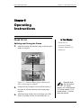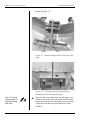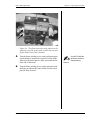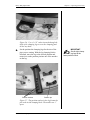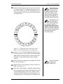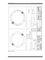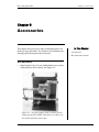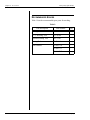
1
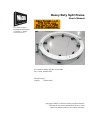
Heavy Duty Split Frame
User’s Manual
E.H. Wachs Company
600 Knightsbridge Parkway
Lincolnshire, IL 60069
www.wachsco.com
E.H. Wachs Company Part No. 06-113-MAN
Rev. 0-1006, October 2006
Revision History:
Original
October 2006
Copyright © 2006 E.H. Wachs Company. All rights reserved.
This manual may not be reproduced in whole or in part
without the written consent of E.H. Wachs Company.
Table of Contents
Chapter 1: About This Manual . . . . . . . . . . . . . . . . . . . . . . . . . . . . . . . . . . . . . . . . . . . . . . . . . 1
Purpose of This Manual . . . . . . . . . . . . . . . . . . . . . . . . . . . . . . . . . . . . . . . . . . . . . . . . . . . . . . . . . 1
How to Use The Manual . . . . . . . . . . . . . . . . . . . . . . . . . . . . . . . . . . . . . . . . . . . . . . . . . . . . . . . . 2
Symbols and Warnings . . . . . . . . . . . . . . . . . . . . . . . . . . . . . . . . . . . . . . . . . . . . . . . . . . . . . . . . . 2
Manual Updates and Revision Tracking . . . . . . . . . . . . . . . . . . . . . . . . . . . . . . . . . . . . . . . . . . . . 3
Chapter 2: Safety . . . . . . . . . . . . . . . . . . . . . . . . . . . . . . . . . . . . . . . . . . . . . . . . . . . . . . . . . . . . . 5
Operator Safety . . . . . . . . . . . . . . . . . . . . . . . . . . . . . . . . . . . . . . . . . . . . . . . . . . . . . . . . . . . . . . . 5
Protective Equipment Requirements . . . . . . . . . . . . . . . . . . . . . . . . . . . . . . . . . . . . . . . . . . . . 6
Safety Labels . . . . . . . . . . . . . . . . . . . . . . . . . . . . . . . . . . . . . . . . . . . . . . . . . . . . . . . . . . . . . . . . . 6
Machine Safety . . . . . . . . . . . . . . . . . . . . . . . . . . . . . . . . . . . . . . . . . . . . . . . . . . . . . . . . . . . . . . . 7
Chapter 3: Introduction to the Heavy Duty Split Frame . . . . . . . . . . . . . . . . . . . . . . . . . . . . 9
Usage and Applications . . . . . . . . . . . . . . . . . . . . . . . . . . . . . . . . . . . . . . . . . . . . . . . . . . . . . . . . . 9
Mechanical Overview . . . . . . . . . . . . . . . . . . . . . . . . . . . . . . . . . . . . . . . . . . . . . . . . . . . . . . . . . . 9
Accessories . . . . . . . . . . . . . . . . . . . . . . . . . . . . . . . . . . . . . . . . . . . . . . . . . . . . . . . . . . . . . . . . . 11
Chapter 4: Assembly, Disassembly, and Storage . . . . . . . . . . . . . . . . . . . . . . . . . . . . . . . . . . 13
Storing the HDSF . . . . . . . . . . . . . . . . . . . . . . . . . . . . . . . . . . . . . . . . . . . . . . . . . . . . . . . . . . . . . 14
Environmental Requirements . . . . . . . . . . . . . . . . . . . . . . . . . . . . . . . . . . . . . . . . . . . . . . . . . . . 18
Long-Term Storage . . . . . . . . . . . . . . . . . . . . . . . . . . . . . . . . . . . . . . . . . . . . . . . . . . . . . . . . . . . 19
Shipping . . . . . . . . . . . . . . . . . . . . . . . . . . . . . . . . . . . . . . . . . . . . . . . . . . . . . . . . . . . . . . . . . . . . 19
Chapter 5: Operating Instructions . . . . . . . . . . . . . . . . . . . . . . . . . . . . . . . . . . . . . . . . . . . . . 21
Frame Set-Up . . . . . . . . . . . . . . . . . . . . . . . . . . . . . . . . . . . . . . . . . . . . . . . . . . . . . . . . . . . . . . . . 21
Splitting and Closing the Frame . . . . . . . . . . . . . . . . . . . . . . . . . . . . . . . . . . . . . . . . . . . . . . 21
Mounting The Frame on the Workpiece . . . . . . . . . . . . . . . . . . . . . . . . . . . . . . . . . . . . . . . . 24
Connecting Power . . . . . . . . . . . . . . . . . . . . . . . . . . . . . . . . . . . . . . . . . . . . . . . . . . . . . . . . . . . . 27
Pneumatic Power . . . . . . . . . . . . . . . . . . . . . . . . . . . . . . . . . . . . . . . . . . . . . . . . . . . . . . . . . . 27
Hydraulic Power . . . . . . . . . . . . . . . . . . . . . . . . . . . . . . . . . . . . . . . . . . . . . . . . . . . . . . . . . . 28
Tracking Slide Set-Up . . . . . . . . . . . . . . . . . . . . . . . . . . . . . . . . . . . . . . . . . . . . . . . . . . . . . . . . . 31
Slide Set-Up for Cutting and Beveling . . . . . . . . . . . . . . . . . . . . . . . . . . . . . . . . . . . . . . . . . 32
Slide Set-Up for Offset Cutting . . . . . . . . . . . . . . . . . . . . . . . . . . . . . . . . . . . . . . . . . . . . . . . 35
Operation . . . . . . . . . . . . . . . . . . . . . . . . . . . . . . . . . . . . . . . . . . . . . . . . . . . . . . . . . . . . . . . . . . . 35
Maintenance Notes . . . . . . . . . . . . . . . . . . . . . . . . . . . . . . . . . . . . . . . . . . . . . . . . . . . . . . . . 36
Chapter 6: Routine Maintenance . . . . . . . . . . . . . . . . . . . . . . . . . . . . . . . . . . . . . . . . . . . . . . 37
Lubrication . . . . . . . . . . . . . . . . . . . . . . . . . . . . . . . . . . . . . . . . . . . . . . . . . . . . . . . . . . . . . . . . . . 37
Tool Inserts . . . . . . . . . . . . . . . . . . . . . . . . . . . . . . . . . . . . . . . . . . . . . . . . . . . . . . . . . . . . . . . . . 38
Heavy Duty Split Frame
Chapter 7: Service and Repair . . . . . . . . . . . . . . . . . . . . . . . . . . . . . . . . . . . . . . . . . . . . . . . . 39
Adjusting the Bearings . . . . . . . . . . . . . . . . . . . . . . . . . . . . . . . . . . . . . . . . . . . . . . . . . . . . . . . . 39
Chapter 8: Parts Lists and Drawings . . . . . . . . . . . . . . . . . . . . . . . . . . . . . . . . . . . . . . . . . . . 45
Chapter 9: Accessories . . . . . . . . . . . . . . . . . . . . . . . . . . . . . . . . . . . . . . . . . . . . . . . . . . . . . . . . 59
Accessories . . . . . . . . . . . . . . . . . . . . . . . . . . . . . . . . . . . . . . . . . . . . . . . . . . . . . . . . . . . . . . . . . 59
Recommended Spares . . . . . . . . . . . . . . . . . . . . . . . . . . . . . . . . . . . . . . . . . . . . . . . . . . . . . . . . . 60
Chapter 10: Ordering Information . . . . . . . . . . . . . . . . . . . . . . . . . . . . . . . . . . . . . . . . . . . . .
Ordering Replacement Parts . . . . . . . . . . . . . . . . . . . . . . . . . . . . . . . . . . . . . . . . . . . . . . . . . . . .
Repair Information . . . . . . . . . . . . . . . . . . . . . . . . . . . . . . . . . . . . . . . . . . . . . . . . . . . . . . . . . . .
Warranty Information . . . . . . . . . . . . . . . . . . . . . . . . . . . . . . . . . . . . . . . . . . . . . . . . . . . . . . . . .
Return Goods Address . . . . . . . . . . . . . . . . . . . . . . . . . . . . . . . . . . . . . . . . . . . . . . . . . . . . . . . . .
Part No. 06-113-MAN, Rev. 0-1006
61
61
61
62
62
E.H. Wachs Company
Heavy Duty Split Frame
Chapter 1: About This Manual
Chapter 1
About This Manual
In This Chapter
PURPOSE OF THIS MANUAL
This manual explains how to operate and maintain the
heavy duty split frame with O.D. tracking slides. It includes
instructions for set-up, operation, and maintenance. It also
contains parts lists and diagrams, and troubleshooting
instructions to help you order replacement parts and perform user-serviceable repairs.
PURPOSE OF THIS MANUAL
HOW TO USE THE MANUAL
SYMBOLS AND WARNINGS
MANUAL UPDATES
Before operating the split frame, you should read through
this manual and become familiar with all instructions. At a
minimum, make sure you read and understand the following
chapters:
• Chapter 1, About This Manual
• Chapter 2, Safety
• Chapter 3, Introduction to the Heavy Duty Split Frame
• Chapter 5, Operating Instructions
• Chapter 9, Accessories
If you will be performing service or repairs, make sure you
read and understand these chapters:
• Chapter 1, About This Manual
• Chapter 4, Assembly and Disassembly
• Chapter 6, Routine Maintenance
• Chapter 7, Troubleshooting and Repair.
You will also want to refer to Chapter 8, Parts Lists and
Drawings.
E.H. Wachs Company
Part No. 06-113-MAN, Rev. 0-1006
1
Chapter 1: About This Manual
Heavy Duty Split Frame
HOW TO USE THE MANUAL
Throughout this manual, refer
to this column for warnings,
cautions, and notices with
supplementary information.
This manual is organized to help you quickly find the information you need. Each chapter describes a specific topic on
using or maintaining the equipment.
Each page is designed with two columns. This large column
on the inside of the page contains instructions and illustrations. Use these instructions to operate and maintain the
equipment.
The narrower column on the outside contains additional
information such as warnings, special notes, and definitions.
Refer to it for safety notes and other information.
SYMBOLS AND WARNINGS
The following symbols are used throughout this manual to
indicate special notes and warnings. They appear in the outside column of the page, next to the section they refer to.
Make sure you understand what each symbol means, and
follow all instructions for cautions and warnings.
This is the safety alert symbol. It is used
to alert you to potential personal injury
hazards. Obey all safety messages that
follow this symbol to avoid possible
injury or death.
NOTE
This symbol indicates a user notice.
Notices provide additional information to
supplement the instructions, or tips for
easier operation.
2
Part No. 06-113-MAN, Rev. 0-1006
E.H. Wachs Company
Heavy Duty Split Frame
Chapter 1: About This Manual
MANUAL UPDATES AND REVISION TRACKING
Occasionally, we will update manuals with improved operation or maintenance procedures, or with corrections if necessary. Revised chapters will be available for customers. If
you receive revised chapters for your manual, remove the
old chapters from your binder and replace them with the
new chapters.
Current versions of E.H.
Wachs Company manuals
are also available in PDF format. You can request an
electronic copy of this manual
by emailing customer service
at [email protected].
When a manual is revised, we will update the revision history on the title page and at the bottom of the pages in the
revised chapters. It is important to put the current title page
with the revision history in your manual. This will help you
make sure you have all current information.
You may have factory service or upgrades performed on the
equipment. If this service changes any technical data or
operation and maintenance procedures, we will include
revised sections of the manual when we return the equipment to you. Remove the old chapters from your manual
and replace them with the revised chapters.
E.H. Wachs Company
Part No. 06-113-MAN, Rev. 0-1006
3
Chapter 1: About This Manual
4
Heavy Duty Split Frame
Part No. 06-113-MAN, Rev. 0-1006
E.H. Wachs Company
Heavy Duty Split Frame
Chapter 2: Safety
Chapter 2
Safety
The E.H. Wachs Company takes great pride in designing
and manufacturing safe, high-quality products. We make
user safety a top priority in the design of all our products.
Read this chapter carefully before operating the heavy duty
split frame. It contains important safety instructions and recommendations.
In This Chapter
OPERATOR SAFETY
SAFETY LABELS
SAFETY PRECAUTIONS
MACHINE SAFETY
OPERATOR SAFETY
Follow these guidelines for safe operation of the equipment.
•
•
•
•
READ THE OPERATING MANUAL. Make sure
you understand all setup and operating instructions
before you begin.
INSPECT MACHINE AND ACCESSORIES. Before
starting the machine, look for loose bolts or nuts, leaking lubricant, rusted components, and any other physical
conditions that may affect operation. Properly maintaining the machine can greatly decrease the chances for
injury.
ALWAYS READ PLACARDS AND LABELS. Make
sure all placards, labels, and stickers are clearly legible
and in good condition. You can purchase replacement
labels from E.H. Wachs Company.
KEEP CLEAR OF MOVING PARTS. Keep hands,
arms, and fingers clear of all rotating or moving parts.
Always turn machine off before doing any adjustments
or service.
E.H. Wachs Company
Part No. 06-113-MAN, Rev. 0-1006
Look for this symbol throughout the
manual. It indicates
a personal injury
hazard.
5
Chapter 2: Safety
Heavy Duty Split Frame
•
•
SECURE LOOSE CLOTHING AND JEWELRY.
Secure or remove loose-fitting clothing and jewelry, and
securely bind long hair, to prevent them from getting
caught in moving parts of the machine.
KEEP WORK AREA CLEAR. Keep all clutter and
nonessential materials out of the work area. Only people
directly involved with the work being performed should
have access to the area.
Protective Equipment Requirements
WARNING
Always wear impact resistant eye protection while operating or working near
this equipment.
For additional information on eye and face protection, refer
to Federal OSHA regulations, 29 Code of Federal Regulations, Section 1910.133., Eye and Face Protection and
American National Standards Institute, ANSI Z87.1, Occupational and Educational Eye and Face Protection. Z87.1 is
available from the American National Standards Institute,
Inc., 1430 Broadway, New York, NY 10018.
CAUTION
Personal hearing protection is recommended when operating or working near
this tool.
Hearing protectors are required in high noise areas, 85 dBA
or greater. The operation of other tools and equipment in the
area, reflective surfaces, process noises, and resonant structures can increase the noise level in the area. For additional
information on hearing protection, refer to Federal OSHA
regulations, 29 Code of Federal Regulations, Section
1910.95, Occupational Noise Exposure and ANSI S12.6
Hearing Protectors.
SAFETY LABELS
There is no safety labeling on the heavy duty split frame.
6
Part No. 06-113-MAN, Rev. 0-1006
E.H. Wachs Company
Heavy Duty Split Frame
Chapter 2: Safety
MACHINE SAFETY
To avoid damaging the heavy duty split frame, follow these
usage guidelines.
•
•
Lubricate the machine according to the recommendations in Chapter 6.
Before starting the machine, make sure the star wheel is
aligned as described in Chapter 5.
E.H. Wachs Company
Part No. 06-113-MAN, Rev. 0-1006
7
Chapter 2: Safety
8
Heavy Duty Split Frame
Part No. 06-113-MAN, Rev. 0-1006
E.H. Wachs Company
Heavy Duty Split Frame
Chapter 3: Introduction to the HDSF
Chapter 3
Introduction to the
Heavy Duty Split
Frame
Read this chapter carefully to become familiar with the
components of the heavy duty split frame.
In This Chapter
USAGE AND APPLICATIONS
MECHANICAL OVERVIEW
USAGE AND APPLICATIONS
ACCESSORIES
The heavy duty split frame is a pipe cutting and beveling
machine using outside diameter (O.D.) tracking slides for
even, efficient cutting of pipes that are out of round or that
are not centered within the frame of the machine. The split
frame is available in various sizes, each with a pipe size
range of 12 inches in diameter.
The machine is supplied with a custom storage case to hold
all components and accessories. Keep the split frame stored
in its case when it is not in use.
MECHANICAL OVERVIEW
Figure 3-1 illustrates the components of the heavy duty split
frame. Figure 3-2 shows one of the tracking slides.
Figure 3-3 shows one of the machine’s clamping legs. Refer
to these figures during set-up instructions for identifying the
parts of the machine.
E.H. Wachs Company
Part No. 06-113-MAN, Rev. 0-1006
9
Chapter 3: Introduction to the HDSF
Heavy Duty Split Frame
Splitting jack frame
Rotating ring (top)
Stationary ring (bottom)
Slide mounting position
Split point
Slide mounting position
Split point
Clamping leg
Clamping pad
Figure 3-1. The photo illustrates components of the
4860 (48 inch to 60 inch pipe) heavy duty split frame.
Tool holder
Tracking wheel
End plate
Jacking screw Star wheel
Bar guides
Figure 3-2. The photo shows the components of the
O.D. tracking slide.
10
Part No. 06-113-MAN, Rev. 0-1006
E.H. Wachs Company
Heavy Duty Split Frame
Chapter 3: Introduction to the HDSF
Clamping leg position notches
Clamping pad
Clamping pad alignment rod
Figure 3-3. The photo illustrates the parts of the
clamping leg. There are eight legs used on the HDSF
4860 machine.
ACCESSORIES
•
Speed control valve (for use with hydraulic power units
without built-in flow control). See Figure 3-4.
E.H. Wachs Company
Part No. 06-113-MAN, Rev. 0-1006
11
Chapter 3: Introduction to the HDSF
Heavy Duty Split Frame
Pressure hose from power unit
Pressure hose to HDSF
Flow/speed control lever
Flow bypass circuit
Return hose to power unit
Return hose from HDSF
Figure 3-4. The flow control valve is used to set the
cutting speed of the HDSF when there is no flow control on the hydraulic power unit.
12
Part No. 06-113-MAN, Rev. 0-1006
E.H. Wachs Company
Heavy Duty Split Frame
Chapter 4: Assembly, Disassembly, and Storage
Chapter 4
Assembly,
Disassembly, and
Storage
The major components of the heavy duty split frame are
factory assembled and ready for set-up. The machine is split
apart and packaged in a custom case for shipping and storage, as shown in Figure 4-1. (Depending on the size of the
split frame, the way the components are arranged in the case
may be different.)
In This Chapter
STORING THE HDSF
ENVIRONMENTAL
REQUIREMENTS
LONG-TERM STORAGE
SHIPPING
Figure 4-1. The heavy duty split frame is stored and
shipped in a custom-built case.
See the Set-Up section of Chapter 5 for instructions on
opening the ring for mounting it on a workpiece.
E.H. Wachs Company
Part No. 06-113-MAN, Rev. 0-1006
13
Chapter 4: Assembly, Disassembly, and Storage
Heavy Duty Split Frame
STORING THE HDSF
Split the machine into halves before putting it into the storage case. Reverse this procedure to remove the machine
from the case.
Keep the flow
control valve
assembly out of the
crate until you have stored
both halves of the HDSF ring.
1. Remove the slides, trip assembly, and hydraulic motor
from the machine. Store them in the case as shown in
Figure 4-2.
Slides
Hydraulic motor
Jack
Trip assembly
Figure 4-2. Store the smaller components of the
machine in the bottom of the storage case.
2. Rotate the rotating ring until the split points on both
rings are aligned.
14
Part No. 06-113-MAN, Rev. 0-1006
E.H. Wachs Company
Heavy Duty Split Frame
Chapter 4: Assembly, Disassembly, and Storage
Figure 4-3. Turn the rotating ring so that the split
lines on both rings are aligned.
3. Swivel the frame locking levers in toward the center
of the machine to lock the rotating and stationary rings
together.
4. Turn the frame jacking screw on each split point in to
separate the halves of the ring. Turn the screws until
the dowel pins that align the halves are fully out of
their holes.
Figure 4-4. Turn the frame jacking screw into the
block to separate the frame at the split point.
E.H. Wachs Company
Part No. 06-113-MAN, Rev. 0-1006
15
Chapter 4: Assembly, Disassembly, and Storage
Store the rings in
the case with the
rotating ring side
down.
Heavy Duty Split Frame
5. Attach a crane to one half of the ring using lifting
straps. Lower the ring half into the crate in the position shown in Figure 4-5.
Figure 4-5. Put the first half of the ring into the crate
as shown. The ends of the ring should rest on the support blocks in the corners.
6. Attach the crane to the other half of the ring using lifting straps and lower it into the crate as shown in
Figure 4-6.
Figure 4-6. Put the second half of the ring into the
crate and position it on the taller mounting blocks.
16
Part No. 06-113-MAN, Rev. 0-1006
E.H. Wachs Company
Heavy Duty Split Frame
Chapter 4: Assembly, Disassembly, and Storage
7. Put the flow control assembly in the case alongside the
split frame.
Figure 4-7. Put the flow control assembly along the
side of the case.
8. Strap the split frame to the eye bolts on the bottom of
the crate using the provided straps, as shown in fig.
E.H. Wachs Company
Part No. 06-113-MAN, Rev. 0-1006
17
Chapter 4: Assembly, Disassembly, and Storage
Heavy Duty Split Frame
Figure 4-8. Secure the split frame in the case using
the four straps provided.
ENVIRONMENTAL REQUIREMENTS
The heavy duty split frame can be used in any industrial
environment. The machine can be used for dry cutting or
with coolant applied to the workpiece.
18
Part No. 06-113-MAN, Rev. 0-1006
E.H. Wachs Company
Heavy Duty Split Frame
Chapter 4: Assembly, Disassembly, and Storage
LONG-TERM STORAGE
If you will be storing the heavy duty split frame, take the
following steps to prepare it:
• Make sure the machine is thoroughly cleaned and
cleared of chips and debris.
• Spray the machine with a rust preventative.
• Add a desiccant to the storage case.
• Always store the machine and its accessories in the storage case provided.
SHIPPING
The heavy duty split frame should be shipped in its storage
case. Make sure all components are correctly positioned and
fastened in the case, and securely fasten the case lid.
E.H. Wachs Company
Part No. 06-113-MAN, Rev. 0-1006
19
Chapter 4: Assembly, Disassembly, and Storage
20
Part No. 06-113-MAN, Rev. 0-1006
Heavy Duty Split Frame
E.H. Wachs Company
Heavy Duty Split Frame
Chapter 5: Operating Instructions
Chapter 5
Operating
Instructions
In This Chapter
FRAME SET-UP
Splitting and Closing the Frame
FRAME SET-UP
1. Align the rotating and stationary rings so that the split
CONNECTING POWER
points are aligned.
TRACKING SLIDE SET-UP
OPERATION
Figure 5-1. Turn the rotating ring so that the split
lines on both rings are aligned.
2. Swing the frame locking levers toward the inside of
the frame to lock the stationary and rotating rings
together.
3. Attach the hinge and the jack to the hinge side of the
Required tools:
3/8” hex wrench,
1/2” socket
wrench, 3/4” socket wrench,
7/8” socket wrench, 1-1/8”
socket wrench, 1-1/8 inch
open end wrench.
frame. (The hinge side has two threaded holes, as
E.H. Wachs Company
Part No. 06-113-MAN, Rev. 0-1006
21
Chapter 5: Operating Instructions
Heavy Duty Split Frame
shown in Figure 5-3.)
Hinge
Jack
Figure 5-2. Attach the hinge and the jack to the split
point.
Figure 5-3. The hinge side of the frame has two
threaded holes for attaching the hinge.
Use a 1-1/8 inch
socket wrench to
loosen the swing
latch nuts.
4. There are four swing latches at each split point—two
22
Part No. 06-113-MAN, Rev. 0-1006
on the top (rotating) side of the frame, and two on the
bottom (stationary) side of the frame. Loosen all eight
swing latch nuts and swing the latches out of their
channels.
E.H. Wachs Company
Heavy Duty Split Frame
Chapter 5: Operating Instructions
Figure 5-4. The photo shows the swing latches on the
stationary ring side of the frame. Loosen the nuts and
lift the latches out of their channels.
5. Turn the frame jacking screws on the split point opposite the hinge to separate the two halves of the frame.
Make sure the dowel pins are fully retracted from the
other side of the frame.
Use a 3/8 inch hex
wrench to turn the
frame jacking
screws.
6. Turn the frame jacking screws on the split point with
the hinge to separate the frame. Make sure the dowel
pins are fully retracted.
E.H. Wachs Company
Part No. 06-113-MAN, Rev. 0-1006
23
Chapter 5: Operating Instructions
Heavy Duty Split Frame
Figure 5-5. Turn the frame jacking screw into the
block to separate the frame at the split point.
CAUTION: Make
sure the halves of
the ring do not
close again while
operating the jack. The dowel
pins could bind and break if
they are in the alignment
holes while you are opening
the ring.
7. Operate the frame jack to pull the sides of the hinge
WARNING:
Make sure that no
one is near the split
frame while
operating the lift.
1. Lift the split frame into position over the workpiece.
together. Open the frame as far as necessary to install
it on the workpiece.
Mounting The Frame on the Workpiece
2. Turn the frame jacking screws back out to allow the
split points to close.
3. Reverse the ratchet on the frame jack. Operate the jack
to close the hinge.
4. Push the swing latches back into their channels at all
four locations and tighten the nuts to secure the split
points.
5. Screw the clamping pads all the way into the clamping
legs using a socket wrench inserted through the back
of each clamping leg.
24
Part No. 06-113-MAN, Rev. 0-1006
E.H. Wachs Company
Heavy Duty Split Frame
Chapter 5: Operating Instructions
Figure 5-6. Use a 1-1/8” socket inserted through the
back of the clamping leg to screw the clamping pads
all the way back.
6. Set the position the clamping legs for the size of the
pipe you are cutting. With the leg clamping blocks
loosened, move the leg to the desired position and
rotate it to set the position pin into one of the notches
on the leg.
Position notches
IMPORTANT:
Set all eight clamping legs at the
same position notch.
Position pin
Figure 5-7. The position notches in the leg fit onto the
pin in the inside clamping block. The notches are 1”
apart.
E.H. Wachs Company
Part No. 06-113-MAN, Rev. 0-1006
25
Chapter 5: Operating Instructions
Heavy Duty Split Frame
Figure 5-8. After positioning the leg, tighten the
clamping block bolts to secure it.
7. Insert a 1-1/8” socket through the back of each clamp-
ing leg and adjust them so that the pads are just touching the pipe.
Figure 5-9. Tighten the clamping pads using a 1-1/8”
socket inserted through the back of the clamping leg.
8. Securely tighten all clamping legs to firmly affix the
frame to the pipe.
9. Remove tension on the lift slowly, making sure the
ring does not shift. Remove the lift chains or straps.
26
Part No. 06-113-MAN, Rev. 0-1006
E.H. Wachs Company
Heavy Duty Split Frame
Chapter 5: Operating Instructions
CONNECTING POWER
Pneumatic Power
1. Install the air motor on the motor mount, as shown in
Figure 5-12.
2. Adjust the clearance between the pinion gear and the
rotating frame gear using the pinion clearance adjustment screw (see Figure 5-13). The pinion gear should
be as close as possible to the frame gear without binding.
Figure 5-10. Install the air motor on the frame and
tighten the two bolts (underneath) that secure it.
E.H. Wachs Company
Part No. 06-113-MAN, Rev. 0-1006
The air supply
should provide 95
cfm (2690 lpm).
Maximum pressure should be
no more than 90 psi (1300
bar).
Use the following
tools to attach and
adjust the air
motor: 3/4” socket to tighten
the motor mounting bolts and
the pinion clearance set
screw; 1/2” socket to turn the
pinion clearance adjustment
screw.
27
Chapter 5: Operating Instructions
Heavy Duty Split Frame
Mounting bolts
Pinion clearance Pinion clearance
set screw
adjustment screw
Figure 5-11. Two bolts fasten the air motor mount to
the frame. To set the pinion clearance, loosen the set
screw and turn the adjustment screw. Re-tighten the
set screw.
3. Attach the air line to the connector on the air motor.
Use the following
tools to attach and
adjust the hydraulic
motor: 3/4” socket to tighten
the motor mounting bolts and
the pinion clearance set
screw; 1/2” socket to turn the
pinion clearance adjustment
screw.
28
Hydraulic Power
1. Install the hydraulic motor on the motor mount, as
shown in Figure 5-12.
2. Adjust the clearance between the pinion gear and the
rotating frame gear using the pinion clearance adjustment screw (see Figure 5-13). The pinion gear should
be as close as possible to the frame gear without binding.
Part No. 06-113-MAN, Rev. 0-1006
E.H. Wachs Company
Heavy Duty Split Frame
Chapter 5: Operating Instructions
Figure 5-12. Install the hydraulic motor on the frame
and tighten the two bolts (underneath) that secure it.
Mounting bolts
Pinion clearance Pinion clearance
set screw
adjustment screw
Figure 5-13. Two bolts fasten the motor mount to the
frame. To set the pinion clearance, loosen the set
screw and turn the adjustment screw. Re-tighten the
set screw.
E.H. Wachs Company
Part No. 06-113-MAN, Rev. 0-1006
29
Chapter 5: Operating Instructions
Heavy Duty Split Frame
3. Connect the hoses from the hydraulic power unit
(HPU) to the flow control valve assembly, as shown in
Figure 5-14
4. Connect the hoses from the hydraulic motor on the
split frame to the flow control valve assembly as
shown in Figure 5-14.
Pressure hose from power unit
Pressure hose to HDSF
Flow bypass circuit
Return hose to power unit
Return hose from HDSF
Figure 5-14. Connect the flow control valve as shown
between the HPU and the split frame motor.
5. Set the flow lever on the flow control valve to 0, and
set the flow lever on the motor to the closed position.
6. To operate the split frame, open the flow valve on the
hydraulic motor, then move the flow control lever on
the control valve to increase the flow.
30
Part No. 06-113-MAN, Rev. 0-1006
E.H. Wachs Company
Heavy Duty Split Frame
Chapter 5: Operating Instructions
Flow control lever (in “0” position)
Figure 5-15. Move the flow control lever down to
open flow to the hydraulic motor.
TRACKING SLIDE SET-UP
The tracking slides provide uniform cutting and beveling on
pipes that are out of round or in situations where the split
frame is not centered on the pipe. The spring-tensioned
tracking mechanism allows radial motion (perpendicular to
the side of the pipe) of up to 1/2 inch, keeping the cutting
tool on the pipe at all times and compensating for a maximum 1 inch out-of-roundness.
Two tracking slides are provided. One includes a tool fitting
for a parting tool; the other can hold either a parting tool or
a beveling tool. You can use these slides to perform a cutting and beveling operation, or an offset severing operation
with two parting tools.
E.H. Wachs Company
Part No. 06-113-MAN, Rev. 0-1006
31
Chapter 5: Operating Instructions
Do not tighten the
mounting bolts yet.
You will tighten
them when you finish positioning the slide.
Heavy Duty Split Frame
Slide Set-Up for Cutting and Beveling
1. Position the slide mounting blocks for the parting tool
slide on the split frame rotating ring and insert the
mounting bolts, as shown in Figure 5-16.
Figure 5-16. Install the slide mounting blocks on the
rotating ring. Leave the mounting bolts loose.
The parting tool
slide can be
mounted at either
slide position on the frame.
2. Mount the parting tool slide onto the rotating ring by
Use a 1-1/8 inch
open end wrench
to turn the jacking
nut.
3. Turn the jacking screw on the parting tool slide so that
32
Part No. 06-113-MAN, Rev. 0-1006
sliding the base plate into the channels on the undersides of the slide mounting blocks. Leave the mounting bolts loose.
the end plate is all the way forward (toward the bar
guides). Turn the nut back one turn.
E.H. Wachs Company
Heavy Duty Split Frame
Chapter 5: Operating Instructions
Jacking nut
End plate
Figure 5-17. Turn the slide jacking nut to retract the
end plate all the way back (fully compressing the
springs). After fully retracting, turn the nut back one
turn.
4. Push the slide all the way toward the pipe until the
tracking wheel contacts the pipe surface.
5. Tighten down the bolts on the mounting blocks until
they are just snug enough to keep the slide from moving freely. Do not tighten them completely; the slide
will need to move when you run the machine to set the
high point.
Use a 3/4 inch
socket wrench to
tighten the
mounting bolts.
6. Repeat Steps 1-5 for the beveling tool slide.
7. Release the frame locking levers to allow the rotating
ring to turn.
8. Engage the power and slowly drive the frame around
the pipe one complete rotation. As the tracking wheel
on each slide travels over the surface of the pipe, it
will push the slide back so that it is in position to contact the pipe at the high point (the location where the
clearance is least).
WARNING:
Keep hands and
clothing clear of the
machine while
operating it.
9. Without moving the slides, securely tighten the bolts
E.H. Wachs Company
Part No. 06-113-MAN, Rev. 0-1006
33
Chapter 5: Operating Instructions
Heavy Duty Split Frame
on the slide mounts.
10. Turn the jacking nuts on both slides back until the end
plate almost touches the bar guide.
Jacking nut
End plate
Close this gap to about 1/16”
Figure 5-18. Turn the jacking nut back until the end
plate is almost fully retracted. There should be about
1/16” clearance between the endplate collar and the
jacking nut post.
Use a 1-1/8 inch
socket wrench to
turn the star wheel.
11. Turn the star wheel on the parting tool slide to fully
retract the tool mount away from the pipe.
12. Insert the tool into the tool mount.
13. Turn the star wheel to drive the tool toward the pipe
until the blade is 1/16” from the pipe surface.
14. Repeat Steps 11-13 for the beveling tool slide.
15. Install the trip assembly on the stationary frame.
WARNING:
Keep hands and
clothing clear of the
machine while
operating it.
16. Using the air motor, rotate the frame to position one of
34
Part No. 06-113-MAN, Rev. 0-1006
the star wheels over the trip assembly.
E.H. Wachs Company
Heavy Duty Split Frame
Chapter 5: Operating Instructions
17. Loosen the trip locking lever. Using the trip adjustment knob, slide the trip toward or away from the
frame to position it beneath the star wheel.
Trip lock lever
The height of the
trip is not adjustable. It is fixed in
relation to the slide.
Trip adjustment knob
Figure 5-19. Loosen the trip lock lever and slide the
trip adjustment knob to position the trip beneath the
star wheel on the slide.
Slide Set-Up for Offset Cutting
Follow the same procedure as the previous section for
installing both slides. When you install the beveling tool
slide, insert a parting tool instead of a beveling tool.
The beveling tool slide is designed to hold a parting tool
with a 1/16” offset from the tool in the parting tool slide.
This will result in a cut 1/16” wider than the cut made by a
single parting tool.
CAUTION: Do not
operate the split
frame with a single
parting tool only. A
beveling tool or second parting tool is required to keep
the parting tool from binding
in the cutting groove.
OPERATION
1. Power on the hydraulic power unit or air compressor
supplying power to the machine.
2. If you are using air power, engage the air motor to
start the machine. Adjust the speed with the air motor
controller.
E.H. Wachs Company
Part No. 06-113-MAN, Rev. 0-1006
WARNING:
Keep hands and
clothing clear of the
machine while
operating it.
35
Chapter 5: Operating Instructions
Heavy Duty Split Frame
3. If using hydraulic power, open the flow valve on the
hydraulic motor.
4. If you are using the hydraulic flow control valve,
slowly move the flow control lever on the valve to
provide power to the motor. At the maximum flow of
about 15 gpm, the split frame will rotate at approximately 8.7 RPM.
Make sure that both star wheels are engaging the trip(s) on
every rotation.
Use coolant on the cutting surface to improve cutting and
extend tool life.
If the beveling
blade contacts the
pipe before the
parting blade, stop the
machine and adjust the slides
by turning the star wheel.
As the tools penetrate the pipe surface, watch to make sure
both slides are advancing at the same rate. (Depending on
the type of material being cut, the difference in resistance on
the two tools may cause one to advance more slowly.) If one
slide is advancing too rapidly, slow the machine to the slowest speed possible and retract the slide slightly using a
socket on the star wheel.
CAUTION: Watch
the tracking
wheels to make
sure that they stay
clear of chips.
If you are operating with the split frame horizontal (cutting
a vertical pipe), you may have to clear chips from the tracking wheels. Use compressed air to blow the chips out as the
slides pass, or stop the machine and brush the chips out of
the wheel assembly.
Maintenance Notes
Every 8 hours of operation, remove and clean the tracking
wheel and bearings on both slides.
36
Part No. 06-113-MAN, Rev. 0-1006
E.H. Wachs Company
Heavy Duty Split Frame
Chapter 6: Routine Maintenance
Chapter 6
Routine Maintenance
The heavy duty split frame requires minimal maintenance.
Follow the lubrication guidelines in this chapter.
Clean the slides of all chips and debris after each use. Make
sure that all chips are cleared from around the tracking
wheel.
In This Chapter
LUBRICATION
TOOL INSERTS
LUBRICATION
Before each machining operation, lubricate the slide rods on
both slides.
Lubricate the slide rods using conventional grease
Figure 6-1. Lubricate the slides before each machining operation.
E.H. Wachs Company
Part No. 06-113-MAN, Rev. 0-1006
37
Chapter 6: Routine Maintenance
Heavy Duty Split Frame
Apply standard grease to all grease fittings on the split
frame every time you use the machine.
TOOL INSERTS
Check the sharpness of the tool inserts frequently. Replace
dull inserts as necessary.
38
Part No. 06-113-MAN, Rev. 0-1006
E.H. Wachs Company
Heavy Duty Split Frame
Chapter 7: Service and Repair
Chapter 7
Service and Repair
The heavy duty split frame is a durable system with little
required maintenance. This chapter contains information on
performing machine adjustments and service.
In This Chapter
ADJUSTING THE BEARINGS
ADJUSTING THE BEARINGS
You should adjust the bearings in the split frame if you can
feel play between the rotating and stationary rings. To check
for play, lay the assembled split frame on a work surface
with the rotating ring down. Push back and forth on the stationary ring; if it moves, the bearings need to be adjusted
according to the following procedure.
1. Lay the split frame on the work surface with the rotating ring up.
2. Remove the tool slides, if necessary.
Required tools:
1/4” hex wrench,
3/8” hex wrench,
7/8” socket wrench, 1-1/8”
socket wrench.
3. Align the rotating ring with the stationary ring so that
the split points are aligned.
E.H. Wachs Company
Part No. 06-113-MAN, Rev. 0-1006
39
Chapter 7: Service and Repair
Heavy Duty Split Frame
Figure 7-1. Turn the rotating ring so that the split
lines on both rings are aligned.
4. Set the frame locking lever on both sides of the frame.
Figure 7-2. Swivel the frame locking levers toward
the outside of the frame to lock the stationary and
rotating rings together.
40
Part No. 06-113-MAN, Rev. 0-1006
E.H. Wachs Company
Heavy Duty Split Frame
Chapter 7: Service and Repair
5. There are four swing latches at each split point—two
on the top (rotating) side of the frame, and two on the
bottom (stationary) side of the frame. Loosen all eight
swing latch nuts and swing the latches out of their
channels.
Use a 1-1/8 inch
socket wrench to
loosen the swing
latch nuts.
Figure 7-3. The photo shows the swing latches on the
stationary ring side of the frame. Loosen the nuts and
lift the latches out of their channels.
6. Turn in the frame jacking screws on both split points
to separate the two halves of the frame. Once the
frame is separated, turn the jacking screws back out all
the way.
E.H. Wachs Company
Part No. 06-113-MAN, Rev. 0-1006
Use a 3/8” hex
wrench to turn the
frame jacking
screws.
41
Chapter 7: Service and Repair
Heavy Duty Split Frame
Figure 7-4. Turn the frame jacking screw into the
block to separate the frame at the split point.
7. Pull the two halves of the frame apart.
8. Swing the frame locking lever toward the inside of the
frame to allow the rotating ring to turn.
Perform steps 9-12
for both halves of
the ring.
9. On each half of the frame, turn the rotating ring out of
Check the
condition of all
bearings, and
replace any components that
are worn or damaged.
10. Using a 7/8” socket, loosen the Nylock hex nut on
the stationary ring and remove it. Turn the stationary
ring over to access the bearing nuts on the back.
each bearing just enough to allow the eccentric shafts
to rotate smoothly. Turn the ring back over.
11. Rotate all eccentric shafts so that the notch in the bearing surface points toward the inside of the ring.
12. Slide the rotating ring back into the stationary ring and
reset the frame locking lever.
13. Reassemble the two halves of the frame, aligning the
dowel pins into the corresponding alignment holes.
14. Set all eight swing latches back in their channels and
tighten them to secure the frame.
15. Release the frame locking lever to allow the rotating
ring to turn.
42
Part No. 06-113-MAN, Rev. 0-1006
E.H. Wachs Company
Heavy Duty Split Frame
Chapter 7: Service and Repair
16. Turn the rotating ring so that you can access bearing
#1 (shown in Figure 7-5) through the bearing access
hole in the rotating ring. NOTE: depending on the size
of the split frame, you may need to use the motor drive
to turn the frame.
19
9
1
13
21
7
5
15
17
3
11
12
4
Position the split
frame so that the
section you are
working on hangs over the
edge of the work surface.
You will need to access the
bearing you are adjusting
from both sides of the frame.
Depending on the
size of the split
frame, there may
be a different number of
bearings than shown in the
diagram. Follow the general
pattern of tightening opposite
pairs, then moving to another
pair approximately 90°
around the frame.
16
18
8
6
22
14
2
10
20
Figure 7-5. Tightening order of bearings in split
frame. View is looking down onto rotating ring.
17. Insert a 1/4” hex wrench through the bearing access
hole and turn the eccentric shaft of the bearing clockwise until the bearing feels fully seated in the groove.
Hold the eccentric shaft at this position with the
wrench.
18. On the back of the stationary ring, tighten the Nylock
hex nut for bearing #1.
19. Repeat steps 16-18 for bearing #2, then #3 and #4 in
Use a 7/8” socket
to tighten the
Nylock nuts.
order. (See Figure 7-5.)
20. After these four bearings, re-align the rotating and stationary rings and swivel the frame locking levers back
to the locked positions. If the levers cannot be fully
seated in the locked position, loosen bearings #1-#4
and repeat steps 16-18. Do not proceed until the bear-
E.H. Wachs Company
Part No. 06-113-MAN, Rev. 0-1006
43
Chapter 7: Service and Repair
Heavy Duty Split Frame
ings are adjusted so that the locking levers will seat
properly.
Do NOT force the
bearing tight
against the groove.
21. Starting with bearing #5, use the 1/4” hex wrench to
turn the eccentric shaft counter-clockwise until you
can feel the bearing just touch the groove. While holding the bearing in this position, tighten the Nylock nut
on the back of the stationary ring.
22. Repeat step 21 for the remaining bearings in order.
After adjusting each pair of opposite bearings, set the
frame locking levers to make sure they fully seat. If
the levers do not seat, re-do the adjustment of the pair
of bearings just completed.
23. Go back to bearing #1 and turn the eccentric shaft
back counter-clockwise until it just touches the
groove. While holding the bearing in this position,
tighten the Nylock nut on the back of the stationary
ring.
24. Repeat step 23 for bearings #2 through #4. Check that
locking levers seat after each pair of bearings.
25. After adjusting all bearings, check that the rotating
ring turns freely on the stationary ring. If it doesn’t,
repeat steps 21-24.
26. Looking through the alignment pin hole, turn the
rotating ring through one full revolution and make
sure each bearing turns with the machine. If they
don’t, repeat steps 21-24.
44
Part No. 06-113-MAN, Rev. 0-1006
E.H. Wachs Company
Heavy Duty Split Frame
Chapter 8: Parts Lists and Drawings
Chapter 8
Parts Lists and
Drawings
Refer to the parts lists and drawings in this chapter for
ordering and maintenance.
You can call E.H. Wachs Company service at (800) 3238185 for assistance in ordering.
E.H. Wachs Company
Part No. 06-113-MAN, Rev. 0-1006
45
Chapter 8: Parts Lists and Drawings
Heavy Duty Split Frame
4860 HDSF Frame
1
1
4
38
38
2
1
4
1
38
1
2
38
38
2
2
4
24
2
1
1
1
1
1
1
2
12
03-010-001-60
03-010-002-60
03-010-005
51-017-00
51-018-00
03-010-014
03-010-016
03-010-015
03-010-017
51-024-00
03-010-200
03-010-201
90-095-52
90-045-08
90-211-22
90-121-32
90-125-51
90-062-05
90-225-04
90-317-30
90-205-04
90-215-51
90-205-59
90-175-54
90-072-07
90-214-30
90-093-10
1
1
1
4
4
2
1
1
3
1
1
1
1
1
1
1
1
3
1
1
1
03-010-080
03-010-081
03-010-082
90-050-07
90-070-07
90-091-18
90-095-03
90-075-00
90-095-52
90-086-10
03-010-202
90-059-48
03-010-203
09-025-00
09-026-00
09-027-00
09-028-00
90-098-58
02-215-00
90-074-17
90-074-05
ROTATING RING (60" ID)
STATIONARY RING (60" ID)
GUARD, STRIP
SHAFT, ECCENTRIC
SPACER, BEARING
ARM, HINGE RATCHET
HINGE, MAIN
PLATE, LIFTING
STUD, HINGE
BEARING, GUIDE
RATCHET, HINGE
LOCK, FRAME
WASHER 1/2" SAE
NUT, NYLOCK 1/2-13
3/4-10 x 2-1/4 HHCS Gr 8
7/8-9 x 3-1/4 HHCS Gr 8
7/8 SAE WASHER
5/16-18 x 1/2" BHCS
NUT, NYLOCK 7/8-9
3/4" X 3" SHOULDER SCREW
NUT, NYLOCK
3/4 SAE WASHER
5/8 SAE WASHER
WASHER, X-TRA THICK STAINLESS
BHCS, 3/8-16 X 3/4"
3/4-10 X3" SSS
FHCS 1/2-13 x 1"
ECCENTRIC
ECCENTRIC
HINGE ARM
RACHET
RACHET
GUARD
RACHET
HINGE, MAIN
HINGE, MAIN
HINGE, MAIN
HINGE, MAIN
STUD, HINGE
STUD, HINGE
CLAMP BLOCK
LIFT PLATE
03-010-405 Single Hydraulic Drive
46
HOUSING, PINION
COVER, PINION HOUSING
GEAR, PINION
SHCS, 1/4-20 x 3/4" LNG.
SHCS, 3/8-16 x 3/4" LNG.
HHCS, 1/2-13 x 1-3/4 LNG. (GRADE 8/9)
NUT, 1/2-20 JAM
NUT, 3/8-16 JAM
WASHER, 1/2 SAE
DOWEL PIN, 7/16 DIA. x 1" LNG.
PIN, LOCATING ADJUSTABLE
WDRF KEY 1/4 x 1"
MOTOR
QD, FEMALE
QD, MALE
DUST CAP, MALE QD
DUST CAP, FEMALE QD
NIPPLE, 1/2 HEX HP
BALL VALVE
SSS, 3/8-16 X 3/4 OVAL POINT
SSS, 3/8-16 X 1/2
Part No. 06-113-MAN, Rev. 0-1006
COVER, PINION HOUSING
MOTOR, HYDRAULIC
HOUSING, PINION
HOUSING, PINION
HOUSING, PINION
2 HOUSING, 1 ADJ. LOCATING PIN
HOUSING, PINION
HOUSING, PINION
SHAFT, MOTOR
PIN, LOCATING ADJUSTABLE
GEAR, PINION
E.H. Wachs Company
Heavy Duty Split Frame
Qty
1
1
4
32
32
2
1
4
1
32
43'
1
2
32
32
2
2
4
2
24
1
1
1
1
2
12
1
1
1
1
1
1
4
4
2
1
1
3
1
1
1
1
1
1
1
1
4
Chapter 8: Parts Lists and Drawings
3648 Split Frame (4 or 8 leg mount)
Part No.
Description
03-010-001-48
ROTATING RING (48" ID)
03-010-002-48
STATIONARY RING (48" ID)
03-010-005
GUARD, STRIP
51-017-00
SHAFT, ECCENTRIC
51-018-00
SPACER, BEARING
03-010-014
ARM, HINGE RATCHET
03-010-016
HINGE, MAIN
03-010-015
PLATE, LIFTING
03-010-017
STUD, HINGE
51-024-00
BEARING, GUIDE
SEAL, FELT WIPER
RATCHET, HINGE
LOCK, FRAME
90-095-52
WASHER 1/2" SAE
90-045-08
NUT, NYLOCK 1/2-13
3/4-10 x 2-1/4 HHCS Gr 8
7/8-9 x 3-1/4 HHCS Gr 8
7/8 SAE WASHER
NUT, NYLOCK 7/8-9
90-062-05
5/16-18 x 1/2" BHCS
3/4" X 3" SHOULDER SCREW
NUT, NYLOCK
90-215-51
3/4 SAE WASHER
90-205-59
5/8 SAE WASHER
3/4-10 X3" SSS
FHCS 1/2-13 x 1"
WASHER, X-TRA THICK STAINLESS
90-072-07
BHCS, 3/8-16 X 3/4"
Pneumatic Drive
03-010-080
03-010-081
03-010-082
66-100-00
02-106-00
90-098-01
E.H. Wachs Company
HOUSING, PINION
COVER, PINION HOUSING
GEAR, PINION
MOTOR, PNEUMATIC
SHCS, 5/16-18 x 3/4" LNG.
SHCS, 1/4-20 x 3/4" LNG.
HHCS, 1/2-13 x 1-3/4 LNG. (GRADE 8/9)
NUT, 1/2-20 JAM
NUT, 3/8-16 JAM
WASHER, 1/2 SAE
DOWEL PIN, 7/16 DIA. x 1" LNG.
PIN, LOCATING ADJUSTABLE
WDRF KEY 1/4 x 1"
GEAR
SSS, FLAT POINT, 3/8-16 X 1" LNG.
SSS, CUP POINT, 3/8-16 X 3/4" LNG
CONTROL, SPEED
OILER, AIRLINE
NIPPLE, 1/2" NPT
Part No. 06-113-MAN, Rev. 0-1006
47
Heavy Duty Split Frame
Chapter 8: Parts Lists and Drawings
03-010-401 OD Tracking Slide Assembly
2
4
4
12
4
2
2
2
2
2
2
2
2
2
2
2
1
1
2
2
2
2
8
2
2
2
2
6
4
4
2
2
2
4
2
1
1
1
12
6
8
6
6
12
8
4
12
2
2
4
2
16
03-010-030
03-010-031
03-010-032
03-010-033
03-010-034
03-010-035
03-010-036
03-010-037
03-010-038
03-010-040
03-010-041
03-010-042
03-010-043
03-010-044
03-010-045
03-010-046
03-010-047
03-010-048
03-010-049
03-010-050
03-010-206
03-010-207
03-010-208
03-010-209
03-010-210
03-010-211
03-010-212
03-010-213
03-010-214
03-010-215
03-010-216
03-010-217
03-010-218
03-010-219
03-010-220
90-800-30
90-800-29
90-800-40
90-050-10
90-070-10
90-070-12
90-070-15
90-070-17
90-070-25
90-073-10
90-091-12
90-091-15
90-091-41
90-064-05
90-066-07
90-066-61
90-095-54
E.H. Wachs Company
PLATE, BASE
CLAMP, SLIDE
BAR, GUIDE
MOUNT, GUIDE BAR
RETAINER, SPRING
SLIDE, TOOL
PLATE, TRACKING BAR END
BAR, TRACKING
STARWHEEL
SCREW, FEED
NUT, FEED
BUSHING, TRACKING BAR
BLOCK, FEED SCREW
NUT, SLIDE RETRACTING
WHEEL, TRACKING
PIN, TRACKING WHEEL
HOLDER, COMBINATION TOOL
HOLDER, TOOL
PLATE, TOOL RETAINING
PIN, SLIDE COUPLING
BEARING, .75 x .875 x .50 LG. SLEEVE
BEARING, 2.0 x 2.188 x 1.5 LG. SLEEVE
BEARING, 1.003 x 1.253 x 1.0 LG. SLEEVE
BEARING, .753 x .878 x 1.5 LG. SLEEVE
BEARING, .750 x 1.00 x .75 LG. NEEDLE
BEARING, .75 x 1.25 x .0781 THRUST NEEDLE
BEARING, .50 x .937 x .0781 THRUST NEEDLE
WASHER, .75 x 1.25 x .063 THRUST
WASHER, .50 x .937 x .032 THRUST
WASHER, 1.0 X 1.75 x .058 THRUST
WASHER, .75 x 1.072 x .015 WAVE
RING, .937 x .021 W. - I.D. RETAINING
RING, .585 x .025 W. - O.D. RETAINING
SPRING, .1.795 x 1.271 x 6 LG.
COLLAR .75 x 1.5 x .50 SHAFT
WRENCH, 3/4" COMBINATION
WRENCH, 1-1/8" COMBINATION
WRENCH, LARGE HEX KEY SET
SHCS, 1/4-20 x 1" LG.
SHCS, 3/8-16 x 1" LG.
SHCS, 3/8-16 x 1-1/4" LG.
SHCS, 3/8-16 x 1-1/2" LG.
SHCS, 3/8-16 x 1-3/4" LG.
SHCS, 3/8-16 x 2-1/2" LG.
FHCS, 3/8-16 x 1" LG.
HHCS, 1/2-13 x 1-1/4" LG. (GRADE 8/9)
HHCS, 1/2-13 x 1-1/2" LG. (GRADE 8/9)
HHCS, 1/2-13 x 4" LG. FULLY THREADED (GRADE 8/9)
SSS, 5/16-18 x 1/2" LG.
PIN, 5/16 x 3/4, DOWEL
PIN, 5/16 x 1-1/8, ROLL
WASHER, 1/2" HARDENED
Part No. 06-113-MAN, Rev. 0-1006
TRACK BAR END PLATE
SLIDE
SLIDE
FEED SCREW BLOCK
TRACKING ROLLER
FEED SCREW BLOCK
SPRING RETRACT
FEED SCREW
SPRING RETRACT
TRACKING WHEEL
FEED SCREW
SPRING RETRACT
PIN, SLIDE COUPLING
SLIDE
FEED SCREW
TRACK BAR END PLATE
TOOL HOLDER
TOOL RETAINING PLATE
TOOL HOLDER
TOOL HOLDER (BEVEL TOOL)
GUIDE BAR MOUNT
FEED SCREW BLOCK
GUIDE BAR
SLIDE CLAMP
TOOL SLIDE RETRACT
TRACKING BAR
TOOL SLIDE
STARWHEEL
12 SLIDE CLAMP /4 GUIDE BAR
48
Chapter 8: Parts Lists and Drawings
Heavy Duty Split Frame
03-010-403 Spring Loaded Trip Assembly
1
1
1
1
1
1
1
1
1
3
1
3
1
03-010-062
03-010-063
03-010-064
03-010-065
03-010-066
03-010-228
03-010-229
03-010-230
20-033-00
90-091-20
90-074-10
90-095-54
90-046-06
4
90-086-10
TRIP, FEED
HOUSING, FEED TRIP
RETAINER, FEED TRIP
BLOCK, TRIP POSITIONING
BLOCK, TRIP MOUNTING
SPRING, .329 x .211 x 2 LG.
T-NUT, .625 SLOT x 1.0 WIDE x 1/2-13 THD.
HANDLE
KNOB
HHCS, 1/2-13 x 2" LG.
SSS, 3/8-16 X 1" LNG
WASHER, 1/2" HARDENED
PIN, 3/16 x 5/8, DOWEL
2 TRIP MNT BAR / 1 TRIP HSG
KNOB
2 TRIP MNT BAR / 1 TRIP HSG
TRIP PIN
PIN, 7/16 x 1, DOWEL
TRIP MOUNTING BAR
TRIP
TRIP MOUNT
BLOCK, TRIP POSITIONING
03-010-412 Leg Assembly
8
8
8
16
8
8
1
1
1
32
16
8
8
03-010-070
03-010-071
03-010-075
03-010-073
03-010-222
03-010-223
90-800-63
90-800-37
90-800-32
90-091-41
90-095-54
90-086-10
90-086-15
1
2
1
1
1
1
2
2
2
4
2
2
2
2
03-010-136
03-010-138
03-010-225
90-098-58
03-010-226
03-010-227
03-010-137
90-050-30
90-055-06
90-055-03
09-025-00
09-026-00
09-027-00
09-028-00
HOUSING, CLAMP LEG REV a
SCREW, CLAMP LEG
FOOT ASSEMBLY
BLOCK, CLAMP LEG MOUNTING
WASHER, 1.0 x 1.562 x .063 THRUST
RING, 1.00 . x .042 W. - O.D RETAINING
WRENCH, 1/2" RATCHET
EXTENTION, 1/2" x 5" LG. SOCKET
SOCKET, 1-1/8" SIX POINT x 1/2"
HHCS, 1/2-13 x 4" LG. (GRADE 8/9)
WASHER, 1/2" HARDENED
PIN, 7/16 x 1", DOWEL
PIN, 7/16 x 1-1/2", DOWEL
CLAMP LEG
LEGS
CLAMP LEG
CLAMP LEG
CLAMP LEG
CLAMP LEG MOUNTING BLOCK
CLAMP LEG MOUNTING BLOCK
CLAMP LEG MOUNTING BLOCK
CLAMP LEG MOUNTING BLOCK
03-010-413 Hydraulic Speed Control
49
AIR CADDY WELDMENT
SPACER
FLOW CONTROL
NIPPLE, 1/2 HEX HP
ELBOW, 1/2 MPT X 3/4-16 SAE 37 X 90 DEGREE
TEE, 3/4-16 SAE 37 X 1/2 MPT X 1/2 MPT
HOSE ASSEMBLY
SHCS, 1/4-20 X 3
NUT, 1/4-20 NYLOCK
WASHER, 1/4 FLAT
QD, FEMALE
QD, MALE
DUST CAP, MALE QD
DUST CAP, FEMALE QD
Part No. 06-113-MAN, Rev. 0-1006
E.H. Wachs Company
Heavy Duty Split Frame
Chapter 8: Parts Lists and Drawings
3648 heavy duty split frame.
E.H. Wachs Company
Part No. 06-113-MAN, Rev. 0-1006
50
Heavy Duty Split Frame
Chapter 8: Parts Lists and Drawings
Frame components
E.H. Wachs Company
Part No. 06-113-MAN, Rev. 0-1006
51
Chapter 8: Parts Lists and Drawings
Heavy Duty Split Frame
Tracking slide components (1 of 2)
52
Part No. 06-113-MAN, Rev. 0-1006
E.H. Wachs Company
Heavy Duty Split Frame
Chapter 8: Parts Lists and Drawings
Tracking slide components (2 of 2)
E.H. Wachs Company
Part No. 06-113-MAN, Rev. 0-1006
53
Chapter 8: Parts Lists and Drawings
54
Heavy Duty Split Frame
Part No. 06-113-MAN, Rev. 0-1006
E.H. Wachs Company
Heavy Duty Split Frame
Chapter 8: Parts Lists and Drawings
Drive Components
E.H. Wachs Company
Part No. 06-113-MAN, Rev. 0-1006
55
Chapter 8: Parts Lists and Drawings
56
Heavy Duty Split Frame
Part No. 06-113-MAN, Rev. 0-1006
E.H. Wachs Company
Heavy Duty Split Frame
Chapter 9: Accessories
Chapter 9
Accessories
This chapter lists accessories and recommended spares for
the heavy duty split frame. See Chapter 8 for information on
ordering replacement parts and accessories.
In This Chapter
ACCESSORIES
RECOMMENDED SPARES
ACCESSORIES
•
Speed control valve (for use with hydraulic power units
without built-in flow control). See Figure 9-1.
Figure 9-1. The flow control valve is used to set the
cutting speed of the HDSF when there is no flow control on the hydraulic power unit.
E.H. Wachs Company
Part No. 06-113-MAN, Rev. 0-1006
59
Chapter 9: Accessories
Heavy Duty Split Frame
RECOMMENDED SPARES
Table 1 lists the recommended spare parts for stocking.
Table 1:
Part Description
60
Part Number
Qty
Parting Tool
43-711-01
37.5° Beveling Tool
53-703-00
Optional Parting Tool
60-711-01
Facing Tool
52-701-01
Tool Holders
03-010-710
1
03-010-711
1
03-010-712
1
Part No. 06-113-MAN, Rev. 0-1006
E.H. Wachs Company
Heavy Duty Split Frame
Chapter 10: Ordering Information
Chapter 10
Ordering Information
To place an order, request service, or get more detailed
information on any E.H. Wachs Company products, call us
at one of the following numbers:
In This Chapter
REPLACEMENT PARTS
REPAIR INFORMATION
U.S.
800-323-8185
International: 847-537-8800
WARRANTY INFORMATION
RETURN GOODS ADDRESS
ORDERING REPLACEMENT PARTS
When ordering parts, refer to the parts lists in Chapter 8.
Please provide the part description and part number for all
parts you are ordering.
REPAIR INFORMATION
Please call us for an authorization number before returning
any equipment for repair or factory service. We will advise
you of shipping and handling. When you send the equipment, please include the following information:
• Your name/company name
• Your address
• Your phone number
• A brief description of the problem or the work to be
done.
Before we perform any repair, we will estimate the work
and inform you of the cost and the time required to complete it.
E.H. Wachs Company
Part No. 06-113-MAN, Rev. 0-1006
61
Chapter 10: Ordering Information
Heavy Duty Split Frame
WARRANTY INFORMATION
Enclosed with the manual is a warranty card. Please fill out
the registration card and return to E.H. Wachs Company.
Retain the owner’s registration record and warranty card for
your information.
RETURN GOODS A DDRESS
Return equipment for repair to the following address.
E.H. Wachs Company
600 Knightsbridge Parkway
Lincolnshire, Illinois 60069 USA
62
Part No. 06-113-MAN, Rev. 0-1006
E.H. Wachs Company