1
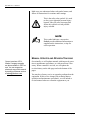
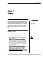
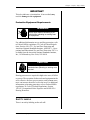
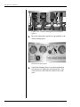
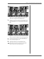
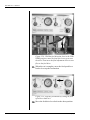
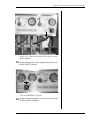
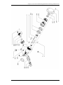
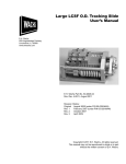
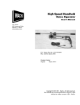
Rail Mill
User’s Manual
E.H. Wachs Company
600 Knightsbridge Parkway
Lincolnshire, IL 60069
www.wachsco.com
E.H. Wachs Company Part No. 03-012-MAN
Rev. 0-0307, March 2007
Revision History:
Original
March 2007
Revision 1
June 2007
Copyright © 2007 E.H. Wachs Company. All rights reserved.
This manual may not be reproduced in whole or in part
without the written consent of E.H. Wachs Company.
Rail Mill User’s Manual
Part No. 03-012-MAN, Rev. 1-0607
E.H. Wachs Company
Table of Contents
Table of Contents
Chapter 1: About this Manual . . . . . . . . . . . . . . . . . . . . . . . . . . . . . . . . . . . . . . . . . . . . . . . . . . 1
Purpose of This Manual . . . . . . . . . . . . . . . . . . . . . . . . . . . . . . . . . . . . . . . . . . . . . . . . . . . . . . . . . 1
How to Use The Manual . . . . . . . . . . . . . . . . . . . . . . . . . . . . . . . . . . . . . . . . . . . . . . . . . . . . . . . . 1
Symbols and Warnings . . . . . . . . . . . . . . . . . . . . . . . . . . . . . . . . . . . . . . . . . . . . . . . . . . . . . . . . . 1
Manual Updates and Revision Tracking . . . . . . . . . . . . . . . . . . . . . . . . . . . . . . . . . . . . . . . . . . . . 2
Chapter 2: Safety . . . . . . . . . . . . . . . . . . . . . . . . . . . . . . . . . . . . . . . . . . . . . . . . . . . . . . . . . . . . . 3
Operator Safety . . . . . . . . . . . . . . . . . . . . . . . . . . . . . . . . . . . . . . . . . . . . . . . . . . . . . . . . . . . . . . . 3
Safety Symbols . . . . . . . . . . . . . . . . . . . . . . . . . . . . . . . . . . . . . . . . . . . . . . . . . . . . . . . . . . . . 4
Protective Equipment Requirements . . . . . . . . . . . . . . . . . . . . . . . . . . . . . . . . . . . . . . . . . . . . 5
Safety Labels . . . . . . . . . . . . . . . . . . . . . . . . . . . . . . . . . . . . . . . . . . . . . . . . . . . . . . . . . . . . . . . . . 5
Machine Safety . . . . . . . . . . . . . . . . . . . . . . . . . . . . . . . . . . . . . . . . . . . . . . . . . . . . . . . . . . . . . . . 6
Chapter 3: Set-Up and Operation . . . . . . . . . . . . . . . . . . . . . . . . . . . . . . . . . . . . . . . . . . . . . . . 7
Clamping the Mill to the Workpiece . . . . . . . . . . . . . . . . . . . . . . . . . . . . . . . . . . . . . . . . . . . . . . . 7
Securing the Chain-Clamping Model . . . . . . . . . . . . . . . . . . . . . . . . . . . . . . . . . . . . . . . . . . 11
Securing the Cable-Clamping Model . . . . . . . . . . . . . . . . . . . . . . . . . . . . . . . . . . . . . . . . . . 12
Hydraulic Connections . . . . . . . . . . . . . . . . . . . . . . . . . . . . . . . . . . . . . . . . . . . . . . . . . . . . . . . . 14
Machine-Mounted Controls . . . . . . . . . . . . . . . . . . . . . . . . . . . . . . . . . . . . . . . . . . . . . . . . . . 14
Topside Control Unit . . . . . . . . . . . . . . . . . . . . . . . . . . . . . . . . . . . . . . . . . . . . . . . . . . . . . . . 14
Connect Hoses to TCU . . . . . . . . . . . . . . . . . . . . . . . . . . . . . . . . . . . . . . . . . . . . . . . . . . 14
Connect Hoses to the Rail Mill . . . . . . . . . . . . . . . . . . . . . . . . . . . . . . . . . . . . . . . . . . . . 16
Installing the Blade . . . . . . . . . . . . . . . . . . . . . . . . . . . . . . . . . . . . . . . . . . . . . . . . . . . . . . . . . . . 18
Operating the Mill . . . . . . . . . . . . . . . . . . . . . . . . . . . . . . . . . . . . . . . . . . . . . . . . . . . . . . . . . . . . 20
Machine-Mounted Controls . . . . . . . . . . . . . . . . . . . . . . . . . . . . . . . . . . . . . . . . . . . . . . . . . . 20
Topside Control Unit . . . . . . . . . . . . . . . . . . . . . . . . . . . . . . . . . . . . . . . . . . . . . . . . . . . . . . . 22
Removing the Mill . . . . . . . . . . . . . . . . . . . . . . . . . . . . . . . . . . . . . . . . . . . . . . . . . . . . . . . . . . . . 29
Removing the Chain-Clamping Model . . . . . . . . . . . . . . . . . . . . . . . . . . . . . . . . . . . . . . . . . 29
Removing the Cable-Clamping Model . . . . . . . . . . . . . . . . . . . . . . . . . . . . . . . . . . . . . . . . . 30
Chapter 4: Routine Maintenance . . . . . . . . . . . . . . . . . . . . . . . . . . . . . . . . . . . . . . . . . . . . . . . 33
Lubrication . . . . . . . . . . . . . . . . . . . . . . . . . . . . . . . . . . . . . . . . . . . . . . . . . . . . . . . . . . . . . . . . . . 33
Chapter 5: Parts Lists and Ordering Information . . . . . . . . . . . . . . . . . . . . . . . . . . . . . . . . . 35
Drawings and Parts Lists . . . . . . . . . . . . . . . . . . . . . . . . . . . . . . . . . . . . . . . . . . . . . . . . . . . . . . . 35
Ordering Information . . . . . . . . . . . . . . . . . . . . . . . . . . . . . . . . . . . . . . . . . . . . . . . . . . . . . . . . . . 46
Ordering Replacement Parts . . . . . . . . . . . . . . . . . . . . . . . . . . . . . . . . . . . . . . . . . . . . . . . . . 46
Repair Information . . . . . . . . . . . . . . . . . . . . . . . . . . . . . . . . . . . . . . . . . . . . . . . . . . . . . . . . . 46
Warranty Information . . . . . . . . . . . . . . . . . . . . . . . . . . . . . . . . . . . . . . . . . . . . . . . . . . . . . . 46
Return Goods Address . . . . . . . . . . . . . . . . . . . . . . . . . . . . . . . . . . . . . . . . . . . . . . . . . . . . . . 46
E.H. Wachs Company
Part No. 03-012-MAN, Rev. 1-0607
1
Rail Mill User’s Manual
2
Part No. 03-012-MAN, Rev. 1-0607
E.H. Wachs Company
Chapter 1, About this Manual
Chapter 1
About this Manual
PURPOSE OF THIS MANUAL
This manual explains how to operate and maintain the rail
mill. It includes instructions for set-up, operation, and
maintenance. It also contains parts lists and diagrams to
help you order replacement parts and perform user-serviceable repairs.
In This Chapter
PURPOSE OF THIS MANUAL
HOW TO USE THE MANUAL
SYMBOLS AND WARNINGS
MANUAL UPDATES AND
REVISION TRACKING
HOW TO USE THE MANUAL
This manual is organized to help you quickly find the information you need. Each chapter describes a specific topic on
using or maintaining the equipment.
Throughout this manual, refer
to this column for warnings,
cautions, and notices with
supplementary information.
Each page is designed with two columns. This large column on the inside of the page contains instructions and
illustrations. Use these instructions to operate and maintain
the equipment.
The narrower column on the outside contains additional
information such as warnings, special notes, and definitions. Refer to it for safety notes and other information.
SYMBOLS AND WARNINGS
The following symbols are used throughout this manual to
indicate special notes and warnings. They appear in the outside column of the page, next to the section they refer to.
E.H. Wachs Company
Part No. 03-012-MAN, Rev. 1-0607
1
Rail Mill User’s Manual
Make sure you understand what each symbol means, and
follow all instructions for cautions and warnings.
This is the safety alert symbol. It is used
to alert you to potential personal injury
hazards. Obey all safety messages that
follow this symbol to avoid possible
injury or death.
NOTE
This symbol indicates a user notice.
Notices provide additional information to
supplement the instructions, or tips for
easier operation.
MANUAL UPDATES AND REVISION TRACKING
Current versions of E.H.
Wachs Company manuals
are also available in PDF format. You can request an
electronic copy of this manual
by emailing customer service
at [email protected].
Occasionally, we will update manuals with improved operation or maintenance procedures, or with corrections if necessary. When a manual is revised, we will update the
revision history on the title page and at the bottom of the
pages.
2
Part No. 03-012-MAN, Rev. 1-0607
You may have factory service or upgrades performed on the
equipment. If this service changes any technical data or
operation and maintenance procedures, we will include a
revised manual when we return the equipment to you.
E.H. Wachs Company
Chapter 2, Safety
Chapter 2
Safety
In This Chapter
The E.H. Wachs Company takes great pride in designing
and manufacturing safe, high-quality products. We make
user safety a top priority in the design of all our products.
Read this chapter carefully before operating the rail mill. It
contains important safety instructions and recommendations.
OPERATOR SAFETY
SAFETY LABELS
MACHINE SAFETY
OPERATOR SAFETY
Follow these guidelines for safe operation of the equipment.
•
•
•
•
READ THE OPERATING MANUAL. Make sure
you understand all setup and operating instructions
before you begin.
INSPECT MACHINE AND ACCESSORIES.
Before starting the machine, look for loose bolts or
nuts, leaking lubricant, rusted components, and any
other physical conditions that may affect operation.
Properly maintaining the machine can greatly decrease
the chances for injury.
ALWAYS READ PLACARDS AND LABELS.
Make sure all placards, labels, and stickers are clearly
legible and in good condition. You can purchase
replacement labels from E.H. Wachs Company.
KEEP CLEAR OF MOVING PARTS. Keep hands,
arms, and fingers clear of all rotating or moving parts.
E.H. Wachs Company
Part No. 03-012-MAN, Rev. 1-0607
Look for this symbol throughout the
manual. It indicates
a personal injury
hazard.
3
Rail Mill User’s Manual
•
•
Always turn machine off before doing any adjustments
or service.
SECURE LOOSE CLOTHING AND JEWELRY.
Secure or remove loose-fitting clothing and jewelry, and
securely bind long hair, to prevent them from getting
caught in moving parts of the machine.
KEEP WORK AREA CLEAR. Keep all clutter and
nonessential materials out of the work area. Only people
directly involved with the work being performed should
have access to the area.
Safety Symbols
This icon is displayed with any safety alert that indicates a
personal injury hazard.
WARNING
This safety alert indicates a potentially hazardous situation
that, if not avoided, could result in death or serious injury.
CAUTION
This safety alert, with the personal injury hazard symbol,
indicates a potentially hazardous situation that, if not
avoided, could result in minor or moderate injury.
NOTICE
This alert indicates a situation that, if not avoided, will
result in damage to the equipment.
4
Part No. 03-012-MAN, Rev. 1-0607
E.H. Wachs Company
Chapter 2, Safety: Safety Labels
IMPORTANT
This alert indicates a situation that, if not avoided, may
result in damage to the equipment.
Protective Equipment Requirements
WARNING
Always wear impact resistant eye protection while operating or working near
this equipment.
For additional information on eye and face protection, refer
to Federal OSHA regulations, 29 Code of Federal Regulations, Section 1910.133., Eye and Face Protection and
American National Standards Institute, ANSI Z87.1, Occupational and Educational Eye and Face Protection. Z87.1 is
available from the American National Standards Institute,
Inc., 1430 Broadway, New York, NY 10018.
CAUTION
Personal hearing protection is recommended when operating or working near
this tool.
Hearing protectors are required in high noise areas, 85 dBA
or greater. The operation of other tools and equipment in the
area, reflective surfaces, process noises, and resonant structures can increase the noise level in the area. For additional
information on hearing protection, refer to Federal OSHA
regulations, 29 Code of Federal Regulations, Section
1910.95, Occupational Noise Exposure and ANSI S12.6
Hearing Protectors.
SAFETY LABELS
There is no safety labeling on the rail mill.
E.H. Wachs Company
Part No. 03-012-MAN, Rev. 1-0607
5
Rail Mill User’s Manual
MACHINE SAFETY
To avoid damaging the equipment, follow these usage
guidelines.
•
•
•
•
6
Lubricate the machinery according to the recommendations in Chapter 4.
Before starting the machine, make sure the blade is
inserted and fastened securely.
Make sure that the chain or cable clamping system is
securely tightened.
Make sure that all hydraulic connections are secure.
Part No. 03-012-MAN, Rev. 1-0607
E.H. Wachs Company
Chapter 3, Set-Up and Operation
Chapter 3
Set-Up and Operation
In This Chapter
This manual explains how to install and operate the rail mill
using either machine-mounted controls or the topside control unit (TCU). Follow the instructions in the appropriate
section for your machine’s configuration.
CLAMPING THE MILL TO THE
WORKPIECE
HYDRAULIC CONNECTIONS
INSTALLING THE BLADE
There are two rail mill models. Model number 03-012 has a
manual plunge drive and uses a 6” milling blade. Model
number 06-150 has a hydraulic plunge drive and uses a 7”
milling blade.
OPERATING THE MILL
REMOVING THE MILL
CLAMPING THE MILL TO THE WORKPIECE
The rail mill cuts from the end with the feed motor and gear
box, toward the opposite end. The maximum length of
travel depends on the size of the rail mill frame.
Position the machine to take into account the direction of
cut. The machine only performs conventional milling, not
climb milling. Figure 3-1 and Figure 3-2 illustrate the
machine’s cutting motions.
E.H. Wachs Company
Part No. 03-012-MAN, Rev. 1-0607
7
Rail Mill User’s Manual
Cutting direction
Figure 3-1. The rail mill is designed to cut only in one
direction, as shown in the photo.
Blade rotation
Cutting direction
Figure 3-2. The blade rotates in the direction shown
as the mill moves.
If you are cutting longer lengths than the rail mill’s maximum travel, you will have to reposition the machine to continue the cut. Be sure to align the cut lines.
1. Attach a crane or hoist to the rail mill at its lifting
locations.
8
Part No. 03-012-MAN, Rev. 1-0607
E.H. Wachs Company
Chapter 3, Set-Up and Operation: Clamping the Mill to the Workpiece
Figure 3-3. Connect a strap or chain to the lifting
points. Use the center point at both ends for horizontal
lifting; use all three points at one end for vertical lifting.
2. Select the appropriate mounting shoes for the size of
the pipe you are cutting. The shoes are different sizes
for the two rail mill models; refer to Table 1 for model
03-012, and Table 2 for model 06-150.
E.H. Wachs Company
Part No. 03-012-MAN, Rev. 1-0607
9
Rail Mill User’s Manual
Table 1: Mounting shoes for 03-012 Rail Mill
Pipe Diameter
Shoe Part No.
Shoe Height
24”
03-012-31
1-1/4”
20”
03-012-32
1-3/4”
16”
03-012-33
2-1/2”
13-3/8”
03-012-34
2-3/4”
10-3/4”
9-5/8”
03-012-35
3-3/8”
7-5/8”
03-012-36
3-5/8”
Table 2: Mounting shoes for 06-150 Rail Mill
Pipe Diameter
Shoe Part No.
Shoe Height
30”
None
--
24”
06-150-005A or 03-012-32
1-3/4”
20”
06-150-005B or 03-012-33
2-1/2”
16”
06-150-005C
3”
13-3/8”
06-150-005D or 03-012-35
3-3/8”
10-3/4”
9-5/8”
06-150-005E
4”
7-5/8”
7”
06-150-005F
4-3/8”
3. Install the four shoes by positioning them inside the
channels at each end of the frame and inserting the
quick release pins.
10
Part No. 03-012-MAN, Rev. 1-0607
E.H. Wachs Company
Chapter 3, Set-Up and Operation: Clamping the Mill to the Workpiece
Figure 3-4. Put each mounting shoe in place and
insert the quick release pin through the frame and
shoe to secure it.
4. Lower the rail mill into position on the workpiece.
Securing the Chain-Clamping Model
1. Wrap the chain at one end of the mill frame around the
casing and loop the chain pins onto the clamp screws.
2. Tighten the clamp nut with the supplied 2-1/2" combination wrench.
Figure 3-5. Tighten the chains to secure the rail mill
to the workpiece.
E.H. Wachs Company
Part No. 03-012-MAN, Rev. 1-0607
11
Rail Mill User’s Manual
3. Secure the chain at the other end of the mill frame in
the same manner.
4. Release the tension on the crane supporting the rail
mill. Leave the crane attached to the mill during cutting.
Securing the Cable-Clamping Model
1. Wrap the cable at one end of the mill around the casing and fasten the hook to the pin on the other side
Figure 3-6. Run the cable around the pipe or casing
and fasten the hook to the pin on the other side of the
mill frame.
2. Use the ratchet handle to tighten the cable.
12
Part No. 03-012-MAN, Rev. 1-0607
E.H. Wachs Company
Chapter 3, Set-Up and Operation: Clamping the Mill to the Workpiece
Figure 3-7. Push the ratchet handle forward to
tighten the cable.
Figure 3-8. If the ratchet is set to turn in the wrong
direction, switch the setting knob to reverse it.
E.H. Wachs Company
Part No. 03-012-MAN, Rev. 1-0607
13
Rail Mill User’s Manual
3. Secure the cable at the other end of the mill frame in
the same manner.
4. Release the tension on the crane supporting the rail
mill. Leave the crane attached to the mill during cutting.
HYDRAULIC CONNECTIONS
Machine-Mounted Controls
One hydraulic hose pair supplies power to the control manifold. Connect the hoses as shown in Figure 3-9.
Figure 3-9. Connect the pressure hose to the fitting
labeled P, and the return (tank) hose to the fitting
labeled T.
Topside Control Unit
If you are operating the rail mill with the optional topside
control unit (TCU), set up the hydraulic connections using
the following procedure.
Connect Hoses to TCU
1. Wipe all hose couplers with a clean, lint free cloth
before making connections.
14
Part No. 03-012-MAN, Rev. 1-0607
E.H. Wachs Company
Chapter 3, Set-Up and Operation: Hydraulic Connections
2. Connect the hoses from the hydraulic power unit
(HPU) to the HPU fittings on the back of the topside
control unit (TCU).
HPU FITTINGS
Return Pressure
Figure 3-10. HPU hose fittings on the back of the
control unit.
3. Connect the cutting drive hose set from the machine or
from the hose reel to the cutting drive fittings on the
back of the TCU. The hoses and fittings are color
coded.
Return
Pressure
CUTTER DRIVE
Figure 3-11. Connect the cutting drive hoses to the
TCU.
4. Connect the auto-plunge hose set to the fittings
labeled “clamp” on the back of the TCU. The hoses
and fittings are color coded.
E.H. Wachs Company
Part No. 03-012-MAN, Rev. 1-0607
15
Rail Mill User’s Manual
Return
Pressure
AUTO-PLUNGE DRIVE
Figure 3-12. Connect the hoses for the auto-plunge
drive to the clamping drive fittings on the TCU.
5. Connect the feed drive hose set to the feed drive fit-
tings on the back of the TCU. The hoses and fittings
are color coded.
Return
Pressure
FEED DRIVE
Figure 3-13. Feed drive connectors (for machines
with hydraulic feed drives).
Connect Hoses to the Rail Mill
1. Connect the auto-plunge drive hoses from the TCU or
hose reel to the fittings on the rail mill bulkhead as
shown in Figure 3-14.
16
Part No. 03-012-MAN, Rev. 1-0607
E.H. Wachs Company
Chapter 3, Set-Up and Operation: Hydraulic Connections
Auto-plunge drive pressure
Auto-plunge drive return
Figure 3-14. Connect the auto-plunge drive hoses to
the mill as shown.
2. Connect the cutting drive hoses from the TCU or hose
reel to the fittings on the rail mill bulkhead as shown
in Figure 3-15.
Cutting drive pressure
Cutting drive return
Figure 3-15. Connect the cutting drive hoses to the
mill as shown.
E.H. Wachs Company
Part No. 03-012-MAN, Rev. 1-0607
17
Rail Mill User’s Manual
3. Connect the feed drive hoses from the TCU or hose
reel to the hoses on the end of the mill as shown in
Figure 3-15.
Feed drive hose fittings
Figure 3-16. Connect the feed drive hoses to the hose
fittings on the end of the rail mill.
NOTE: The feed drive hose fittings are physically interchangeable. If the feed drive is operating in the wrong direction, reverse the hose connections.
INSTALLING THE BLADE
1. Make sure the cutter spindle is in its uppermost position. Use the plunge drive on the TCU to raise the
spindle, or turn the spindle wrench counterclockwise
on the plunge drive nut.
18
Part No. 03-012-MAN, Rev. 1-0607
E.H. Wachs Company
Chapter 3, Set-Up and Operation: Installing the Blade
Figure 3-17. On mills with machine-mounted controls, turn the plunge drive nut counter-clockwise to
retract the spindle.
2. Make sure the cutter drive collar spacer and lock nut
are clean and free of chips and dirt so that the assembly can be tightened securely.
3. Install the cutter onto the spindle shaft. The cutter
should be placed on the spindle so the flat, sharp cutting edges lead into the pipe.
4. Place the driving collar spacer on the spindle and lock
the spacer and cutter tightly to the spindle with the
lock nut.
E.H. Wachs Company
Part No. 03-012-MAN, Rev. 1-0607
NOTE: Left hand thread in
nut turns counter-clockwise
to tighten.
19
Rail Mill User’s Manual
Figure 3-18. Turn the blade nut counter-clockwise, as
shown, to tighten the blade.
OPERATING THE MILL
Machine-Mounted Controls
1. Visually inspect the machine for any loose bolts or fittings. Ensure the controls on the manifold are set to off
or neutral.
2. Turn on the hydraulic power supply and start flow to
the rail mill.
3. The controls for the rail mill are described in Figure 319. Close the bypass valve to direct hydraulic flow
into the manifold.
20
Part No. 03-012-MAN, Rev. 1-0607
E.H. Wachs Company
Chapter 3, Set-Up and Operation: Operating the Mill
Figure 3-19. The photo illustrates the operation of the
machine-mounted control unit.
4. If necessary, turn the feed direction handle to traverse
the carriage to the desired starting position.
5. Turn on the cutter spindle valve.
6. Slowly feed the rotating cutter spindle down until it
extends through the wall of the casing. This is done by
turning the feed screw in a clockwise direction. One
complete turn of the feed screw lowers the cutter 1/
10".
Figure 3-20. Turn the plunge drive nut clockwise to
feed the spindle.
E.H. Wachs Company
Part No. 03-012-MAN, Rev. 1-0607
21
Rail Mill User’s Manual
7. Turn the feed direction valve handle in the forward
direction. The rail mill will begin cutting a longitudinal slit through the casing.
8. Adjust the cutting speed by changing the settings of
the flow control valve.
9. Once the cut is complete, turn off the feed direction
valve and cutter spindle valve.
10. Retract the cutter spindle up into the carriage.
11. Turn feed control valve to the Reverse position to
bring carriage back to start position.
12. Turn off hydraulic fluid to the machine by opening the
bypass valve.
Topside Control Unit
Brief instructions for operating the TCU are on the instruction label on the top of the unit.
Figure 3-21. Instruction label on the topside control
unit.
NOTE: The TCU has fittings and controls for a clamping
drive, which are identified on the unit as “clamp” or
“clamping”. With the rail mill, these controls are used for
the auto-plunge drive.
1. Set all drive power levers to the up (closed) position,
and make sure the clamping (auto-plunge) direction
lever is set to the ENGAGE position.
22
Part No. 03-012-MAN, Rev. 1-0607
E.H. Wachs Company
Chapter 3, Set-Up and Operation: Operating the Mill
Figure 3-22. Before starting the HPU, make sure that
all drive levers are in the up position, and that the
clamping direction lever is in the ENGAGE position.
2. Start the hydraulic power unit.
3. Make sure the cutting drive speed control lever is set
to 0.
Figure 3-23. Set the cutting drive speed lever to 0
before starting the mill.
4. Open the cutting drive lever (down position).
E.H. Wachs Company
Part No. 03-012-MAN, Rev. 1-0607
23
Rail Mill User’s Manual
Figure 3-24. Push the cutting drive lever down to
open it.
5. Move the cutting drive speed lever up gradually to the
desired cutting speed.
Figure 3-25. Push the cutting speed lever up slowly to
the desired cutter speed.
6. Open both clamping drive levers (down position) at
the same time to engage the auto-plunge drive. The
cutter will move down into the surface of the workpiece.
24
Part No. 03-012-MAN, Rev. 1-0607
E.H. Wachs Company
Chapter 3, Set-Up and Operation: Operating the Mill
Figure 3-26. Put both clamping levers down at the
same time to engage the auto-plunge drive.
7. When the cutter has reached the desired depth, close
both clamping drive levers (up position) at the same
time.
Figure 3-27. When the cutter has reached the desired
depth, return both clamping levers to the up position.
8. Set the feed direction lever to the FORWARD position, as shown in Figure 3-28.
9. Open the feed drive lever by pushing it down.
10. Adjust the feed speed lever until the feed motion
starts. Set the lever to the desired speed.
E.H. Wachs Company
Part No. 03-012-MAN, Rev. 1-0607
25
Rail Mill User’s Manual
Figure 3-28. With the feed direction lever in the FORWARD position, move the feed drive lever up to start
the drive. Then move the feed adjustment lever to start
flow to the feed drive.
11. When the cut is complete, move the feed speed lever
back to 0 to stop the feed motion.
Figure 3-29. Stop the feed motion by setting the feed
speed lever back to 0.
12. Move the feed drive lever back to the down position.
26
Part No. 03-012-MAN, Rev. 1-0607
E.H. Wachs Company
Chapter 3, Set-Up and Operation: Operating the Mill
Figure 3-30. Move the feed drive lever down to stop
the feed motion.
13. Set the clamping drive (auto-plunge) direction lever to
the RETRACT position.
Figure 3-31. Set the clamping (auto-plunge) direction
lever to the RETRACT position.
14. Engage both clamping drive levers down to retract the
cutter out of the workpiece.
E.H. Wachs Company
Part No. 03-012-MAN, Rev. 1-0607
27
Rail Mill User’s Manual
Figure 3-32. Push the clamping drive levers down to
reverse the auto-plunge drive.
15. When the cutter is above the workpiece, pull both
clamping drive levers back up.
Figure 3-33. Return both clamping (auto-plunge)
levers back to the up position when the cutter is fully
retracted.
16. To reverse the feed and move the cutting head back to
the start position, set the feed direction lever to the
REVERSE position and use the feed drive lever to
operate the drive.
17. Set the cutting speed lever back to 0 to stop the cutter.
Close the cutting drive lever by moving it to the up
position.
28
Part No. 03-012-MAN, Rev. 1-0607
E.H. Wachs Company
Chapter 3, Set-Up and Operation: Removing the Mill
Figure 3-34. When the cut is complete, set the cutting
speed lever back to 0. Then return the cutting drive
lever to the off (up) position.
REMOVING THE MILL
1. Turn off power to the HPU.
2. Slowly raise the lift holding the mill until there is just
enough tension to hold the mill in place.
Removing the Chain-Clamping Model
1. Loosen the chain tensioning nuts at both ends of the
mill frame, using the supplied 2-1/2” wrench.
E.H. Wachs Company
Part No. 03-012-MAN, Rev. 1-0607
29
Rail Mill User’s Manual
Figure 3-35. Loosen the clamping nuts to release the
tension on the chains.
2. Remove the clamping chains from the slots on the
back of the mill frame.
3. Use the crane to remove the mill from the workpiece.
Removing the Cable-Clamping Model
Use the following procedure to safely loosen the cable
clamp one notch at a time.
1. Set the ratchet on the handle to the forward direction.
Figure 3-36. Push the right-side ratchet knob up to
set the ratchet direction forward.
30
Part No. 03-012-MAN, Rev. 1-0607
E.H. Wachs Company
Chapter 3, Set-Up and Operation: Removing the Mill
2. Push the handle forward just far enough to release the
catch on the cable winch. Push the catch down to disengage it.
Figure 3-37. Turn the handle just enough to release
the catch.
3. Back the handle off one notch of the gear and reset the
catch.
4. Continue to loosen the winch one gear notch at a time
until the cable is loose around the pipe.
5. Remove the cable hook from the pin on the back of the
mill frame.
E.H. Wachs Company
Part No. 03-012-MAN, Rev. 1-0607
31
Rail Mill User’s Manual
Figure 3-38. After loosening the cable, remove the
hook from the pin on the back of the mill frame.
6. Repeat the procedure to remove the cable on the other
end of the mill frame.
7. Use the crane to remove the mill from the workpiece.
32
Part No. 03-012-MAN, Rev. 1-0607
E.H. Wachs Company
Chapter 4, Routine Maintenance
Chapter 4
Routine Maintenance
In This Chapter
LUBRICATION
LUBRICATION
Before each cut, apply grease to all grease fittings on the
machine.
E.H. Wachs Company
Part No. 03-012-MAN, Rev. 1-0607
33
Rail Mill User’s Manual
34
Part No. 03-012-MAN, Rev. 1-0607
E.H. Wachs Company
Chapter 5, Parts Lists and Ordering Information
Chapter 5
Parts Lists and
Ordering Information
In This Chapter
Refer to the part assembly drawings and parts lists that
accompany them for parts identification. To order spare or
replacement parts, see the ordering instructions at the end
of this chapter.
DRAWINGS AND PARTS LISTS
ORDERING INFORMATION
DRAWINGS AND PARTS LISTS
The following drawings with parts lists are provided.
•
•
•
•
•
•
•
•
•
Shoe selection chart
03-012 Axial carriage assembly for manual plunge
machine
03-012 Feed end view for manual plunge machine
03-012 Feed detail for manual plunge machine
06-150 Axial carriage assembly for autoplunge
machine
06-150 Feed end view for autoplunge machine
06-150 Feed detail for autoplunge machine
06-150 Autofeed assembly
02-020-00 Cutter spindle gear housing
E.H. Wachs Company
Part No. 03-012-MAN, Rev. 1-0607
35
Rail Mill User’s Manual
36
Part No. 03-012-MAN, Rev. 1-0607
E.H. Wachs Company
Chapter 5, Parts Lists and Ordering Information: Drawings and Parts Lists
E.H. Wachs Company
Part No. 03-012-MAN, Rev. 1-0607
37
Rail Mill User’s Manual
38
Part No. 03-012-MAN, Rev. 1-0607
E.H. Wachs Company
Chapter 5, Parts Lists and Ordering Information: Drawings and Parts Lists
E.H. Wachs Company
Part No. 03-012-MAN, Rev. 1-0607
39
Rail Mill User’s Manual
40
Part No. 03-012-MAN, Rev. 1-0607
E.H. Wachs Company
Chapter 5, Parts Lists and Ordering Information: Drawings and Parts Lists
E.H. Wachs Company
Part No. 03-012-MAN, Rev. 1-0607
41
Rail Mill User’s Manual
42
Part No. 03-012-MAN, Rev. 1-0607
E.H. Wachs Company
Chapter 5, Parts Lists and Ordering Information: Drawings and Parts Lists
E.H. Wachs Company
Part No. 03-012-MAN, Rev. 1-0607
43
Rail Mill User’s Manual
44
Part No. 03-012-MAN, Rev. 1-0607
E.H. Wachs Company
Chapter 5, Parts Lists and Ordering Information: Drawings and Parts Lists
E.H. Wachs Company
Part No. 03-012-MAN, Rev. 1-0607
45
Rail Mill User’s Manual
ORDERING INFORMATION
To place an order, request service, or get more detailed
information on any E.H. Wachs Company products, call us
at one of the following numbers:
U.S.
800-323-8185
International: 847-537-8800
Ordering Replacement Parts
When ordering parts, refer to the parts lists earlier in this
chapter. Please provide the part description and part number
for all parts you are ordering.
Repair Information
Please call us for an authorization number before returning
any equipment for repair or factory service. We will advise
you of shipping and handling. When you send the equipment, please include the following information:
• Your name/company name
• Your address
• Your phone number
• A brief description of the problem or work to be done.
Before we perform any repair, we will estimate the work
and inform you of the cost and the time required to complete it.
Warranty Information
Enclosed with the manual is a warranty card. Please fill out
the registration card and return to E.H. Wachs Company.
Retain the owner’s registration record and warranty card for
your information.
Return Goods Address
Return equipment for repair to the following address.
E.H. Wachs Company
600 Knightsbridge Parkway
Lincolnshire, Illinois 60069 USA
46
Part No. 03-012-MAN, Rev. 1-0607
E.H. Wachs Company