1
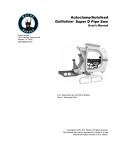
Heavy Duty Split Frame
User’s Manual
E.H. Wachs
600 Knightsbridge Parkway
Lincolnshire, IL 60069
www.ehwachs.com
E.H. Wachs Part No. 03-010-MAN
Rev. 4-0213, February 2013
Revision History:
Original
August 2006
Revision 1
April 2009
Revision 2
June 2009
Revision 3
October 2009
Copyright © 2013 E.H. Wachs. All rights reserved.
This manual may not be reproduced in whole or in part
without the written consent of E.H. Wachs.
EU DECLARATION OF CONFORMITY
WITH
COUNCIL DIRECTIVE 2006/42/EC
Issue Details:
Directives:
Date:
Place:
1/1/2011 E.H. Wachs, Lincolnshire, IL USA
Machinery Safety Directive 2006/42/EC
Conforming Machinery:
Heavy Duty Split Frame Machine
Model Number:
P03-010-4xx
Serial Number:
Manufacturer:
E.H. Wachs Company
600 Knightsbridge Parkway
Lincolnshire
IL 60069
USA
Responsible Representative: Orbitalum Tools GmbH
Josef-Schüttler-Str. 17, 78224 Singen
Germany
Tel. +49 (0) 7731 - 792 872
Fax +49 (0) 7731 - 792 566
Harmonised Standards & EN ISO 12100-1:2003 + A1:2009, EN ISO 12100-2:2003 +
Other
Technical A1:2009, EN ISO 13857:2008, EN 982:1996 + A1:2008
Standards/Specifications
(E), EN 983:1996 + A1:2008 (E), EN 13732-1:2006, EN
ISO 14121-1:2007, EN 60204-1:2006 (for electrical
Applied or Referenced:
machines), EN ISO 13850:2008 (for pneumatic machines)
Provisions with which
Essential Health and Safety Requirements of Annex 1 of the
Conformity is Declared:
Machinery Directive
We hereby certify that the machinery described above conforms to the provisions of
Council Directive 2006/42/EC on the approximation of the laws of the Member States
relating to the safety of machinery.
Signed:
Signatory:
Pete Mullally
Quality Manager
E.H. Wachs
Table of Contents
Table of Contents
Chapter 1: About This Manual . . . . . . . . . . . . . . . . . . . . . . . . . . . . . . . . . . . . . . . . . . . . . . . . . 1
Purpose of This Manual . . . . . . . . . . . . . . . . . . . . . . . . . . . . . . . . . . . . . . . . . . . . . . . . . . . . . . . . . 1
How to Use The Manual . . . . . . . . . . . . . . . . . . . . . . . . . . . . . . . . . . . . . . . . . . . . . . . . . . . . . . . . 2
Symbols and Warnings . . . . . . . . . . . . . . . . . . . . . . . . . . . . . . . . . . . . . . . . . . . . . . . . . . . . . . . . . 2
Manual Updates and Revision Tracking . . . . . . . . . . . . . . . . . . . . . . . . . . . . . . . . . . . . . . . . . . . . 3
Chapter 2: Safety . . . . . . . . . . . . . . . . . . . . . . . . . . . . . . . . . . . . . . . . . . . . . . . . . . . . . . . . . . . . . 5
Operator Safety . . . . . . . . . . . . . . . . . . . . . . . . . . . . . . . . . . . . . . . . . . . . . . . . . . . . . . . . . . . . . . . 5
Safety Symbols . . . . . . . . . . . . . . . . . . . . . . . . . . . . . . . . . . . . . . . . . . . . . . . . . . . . . . . . . . . . 6
Protective Equipment Requirements . . . . . . . . . . . . . . . . . . . . . . . . . . . . . . . . . . . . . . . . . . . . 7
Safety Labels . . . . . . . . . . . . . . . . . . . . . . . . . . . . . . . . . . . . . . . . . . . . . . . . . . . . . . . . . . . . . . . . . 7
Chapter 3: Introduction to the Equipment . . . . . . . . . . . . . . . . . . . . . . . . . . . . . . . . . . . . . . . . 9
Usage and Applications . . . . . . . . . . . . . . . . . . . . . . . . . . . . . . . . . . . . . . . . . . . . . . . . . . . . . . . . . 9
Mechanical Overview . . . . . . . . . . . . . . . . . . . . . . . . . . . . . . . . . . . . . . . . . . . . . . . . . . . . . . . . . 10
Accessories and Options . . . . . . . . . . . . . . . . . . . . . . . . . . . . . . . . . . . . . . . . . . . . . . . . . . . . . . . 14
Operating Envelope . . . . . . . . . . . . . . . . . . . . . . . . . . . . . . . . . . . . . . . . . . . . . . . . . . . . . . . . . . . 15
Chapter 4: Assembly, Disassembly, and Storage . . . . . . . . . . . . . . . . . . . . . . . . . . . . . . . . . . 17
Storing the HDSF . . . . . . . . . . . . . . . . . . . . . . . . . . . . . . . . . . . . . . . . . . . . . . . . . . . . . . . . . . . . . 18
Environmental Requirements . . . . . . . . . . . . . . . . . . . . . . . . . . . . . . . . . . . . . . . . . . . . . . . . . . . . 22
Long-Term Storage . . . . . . . . . . . . . . . . . . . . . . . . . . . . . . . . . . . . . . . . . . . . . . . . . . . . . . . . . . . 22
Shipping . . . . . . . . . . . . . . . . . . . . . . . . . . . . . . . . . . . . . . . . . . . . . . . . . . . . . . . . . . . . . . . . . . . . 23
Chapter 5: Operating Instructions . . . . . . . . . . . . . . . . . . . . . . . . . . . . . . . . . . . . . . . . . . . . . . 25
Frame Set-Up . . . . . . . . . . . . . . . . . . . . . . . . . . . . . . . . . . . . . . . . . . . . . . . . . . . . . . . . . . . . . . . . 25
Splitting and Closing the Frame . . . . . . . . . . . . . . . . . . . . . . . . . . . . . . . . . . . . . . . . . . . . . . 25
Mounting The Frame on the Workpiece . . . . . . . . . . . . . . . . . . . . . . . . . . . . . . . . . . . . . . . . 28
Alternate Clamping Legs . . . . . . . . . . . . . . . . . . . . . . . . . . . . . . . . . . . . . . . . . . . . . . . . . . . . 31
Installing and Connecting the Drive Motor . . . . . . . . . . . . . . . . . . . . . . . . . . . . . . . . . . . . . . . . . 33
Hydraulic Drive . . . . . . . . . . . . . . . . . . . . . . . . . . . . . . . . . . . . . . . . . . . . . . . . . . . . . . . . . . . 33
Dual-Motor Drive Option . . . . . . . . . . . . . . . . . . . . . . . . . . . . . . . . . . . . . . . . . . . . . . . . 37
Air Drive . . . . . . . . . . . . . . . . . . . . . . . . . . . . . . . . . . . . . . . . . . . . . . . . . . . . . . . . . . . . . . . . 37
Tracking Slide Set-Up . . . . . . . . . . . . . . . . . . . . . . . . . . . . . . . . . . . . . . . . . . . . . . . . . . . . . . . . . 39
Slide Set-Up for Cutting and Beveling . . . . . . . . . . . . . . . . . . . . . . . . . . . . . . . . . . . . . . . . . 39
Slide Set-Up for Offset Cutting . . . . . . . . . . . . . . . . . . . . . . . . . . . . . . . . . . . . . . . . . . . . . . . 43
Operation . . . . . . . . . . . . . . . . . . . . . . . . . . . . . . . . . . . . . . . . . . . . . . . . . . . . . . . . . . . . . . . . . . . 43
Chapter 6: Routine Maintenance . . . . . . . . . . . . . . . . . . . . . . . . . . . . . . . . . . . . . . . . . . . . . . . 45
Lubrication . . . . . . . . . . . . . . . . . . . . . . . . . . . . . . . . . . . . . . . . . . . . . . . . . . . . . . . . . . . . . . . . . . 45
E.H. Wachs
Part No. 03-010-MAN, Rev. 4-0213
i
Heavy Duty Split Frame
Tool Inserts . . . . . . . . . . . . . . . . . . . . . . . . . . . . . . . . . . . . . . . . . . . . . . . . . . . . . . . . . . . . . . . . . 46
Cleaning . . . . . . . . . . . . . . . . . . . . . . . . . . . . . . . . . . . . . . . . . . . . . . . . . . . . . . . . . . . . . . . . . . . . 46
Chapter 7: Service and Repair . . . . . . . . . . . . . . . . . . . . . . . . . . . . . . . . . . . . . . . . . . . . . . . . .
Adjusting the Bearings . . . . . . . . . . . . . . . . . . . . . . . . . . . . . . . . . . . . . . . . . . . . . . . . . . . . . . . .
Adjusting the Pinion Gear . . . . . . . . . . . . . . . . . . . . . . . . . . . . . . . . . . . . . . . . . . . . . . . . . . . . . .
Adjusting the Slides . . . . . . . . . . . . . . . . . . . . . . . . . . . . . . . . . . . . . . . . . . . . . . . . . . . . . . . . . . .
Slide Inspection . . . . . . . . . . . . . . . . . . . . . . . . . . . . . . . . . . . . . . . . . . . . . . . . . . . . . . . . . . .
Tracking Wheel Disassembly . . . . . . . . . . . . . . . . . . . . . . . . . . . . . . . . . . . . . . . . . . . . . . . .
Feed Screw Adjustment Procedure . . . . . . . . . . . . . . . . . . . . . . . . . . . . . . . . . . . . . . . . . . . .
Bushing Inspection and Replacement . . . . . . . . . . . . . . . . . . . . . . . . . . . . . . . . . . . . . . . . . .
47
47
52
53
53
54
56
60
Chapter 8: Parts Lists and Drawings . . . . . . . . . . . . . . . . . . . . . . . . . . . . . . . . . . . . . . . . . . .
Parts Lists . . . . . . . . . . . . . . . . . . . . . . . . . . . . . . . . . . . . . . . . . . . . . . . . . . . . . . . . . . . . . . . . . .
Drive Options . . . . . . . . . . . . . . . . . . . . . . . . . . . . . . . . . . . . . . . . . . . . . . . . . . . . . . . . . . . .
Drawings . . . . . . . . . . . . . . . . . . . . . . . . . . . . . . . . . . . . . . . . . . . . . . . . . . . . . . . . . . . . . . . . . . .
63
63
68
75
Chapter 9: Accessories and Spare Parts . . . . . . . . . . . . . . . . . . . . . . . . . . . . . . . . . . . . . . . . . 83
Accessories . . . . . . . . . . . . . . . . . . . . . . . . . . . . . . . . . . . . . . . . . . . . . . . . . . . . . . . . . . . . . . . . . 83
Recommended Spares . . . . . . . . . . . . . . . . . . . . . . . . . . . . . . . . . . . . . . . . . . . . . . . . . . . . . . . . . 84
Chapter 10: Ordering Information . . . . . . . . . . . . . . . . . . . . . . . . . . . . . . . . . . . . . . . . . . . . .
Ordering Replacement Parts . . . . . . . . . . . . . . . . . . . . . . . . . . . . . . . . . . . . . . . . . . . . . . . . . . . .
Repair Information . . . . . . . . . . . . . . . . . . . . . . . . . . . . . . . . . . . . . . . . . . . . . . . . . . . . . . . . . . .
Warranty Information . . . . . . . . . . . . . . . . . . . . . . . . . . . . . . . . . . . . . . . . . . . . . . . . . . . . . . . . .
Return Goods Address . . . . . . . . . . . . . . . . . . . . . . . . . . . . . . . . . . . . . . . . . . . . . . . . . . . . . . . . .
ii
Part No. 03-010-MAN, Rev. 4-0213
85
85
85
86
86
E.H. Wachs
Chapter 1, About This Manual
Chapter 1
About This Manual
In This Chapter
PURPOSE OF THIS MANUAL
This manual explains how to operate and maintain the
heavy duty split frame (HDSF) with O.D. tracking slides. It
includes instructions for set-up, operation, and maintenance.
It also contains parts lists and diagrams to help you order
replacement parts and perform user-serviceable repairs.
PURPOSE OF THIS MANUAL
HOW TO USE THE MANUAL
SYMBOLS AND WARNINGS
MANUAL UPDATES AND
REVISION TRACKING
Before operating the HDSF, you should read through this
manual and become familiar with all instructions. At a minimum, make sure you read and understand the following
chapters:
•
•
•
•
•
Chapter 1, About This Manual
Chapter 2, Safety
Chapter 3, Introduction to the Equipment
Chapter 5, Operating Instructions
Chapter 9, Accessories
If you will be performing service or repairs, make sure you
read and understand these chapters:
•
•
•
•
Chapter 1, About This Manual
Chapter 4, Assembly, Disassembly, and Storage
Chapter 6, Routine Maintenance
Chapter 7, Troubleshooting and Repair.
You will also want to refer to Chapter 8, Parts Lists and
Drawings.
E.H. Wachs
Part No. 03-010-MAN, Rev. 4-0213
1
Heavy Duty Split Frame
HOW TO USE THE MANUAL
Throughout this manual, refer
to this column for warnings,
cautions, and notices with
supplementary information.
This manual is organized to help you quickly find the information you need. Each chapter describes a specific topic on
using or maintaining your equipment.
Each page is designed with two columns. This large column
on the inside of the page contains instructions and illustrations. Use these instructions to operate and maintain the
equipment.
The narrower column on the outside contains additional
information such as warnings, special notes, and definitions.
Refer to it for safety notes and other information.
SYMBOLS AND WARNINGS
The following symbols are used throughout this manual to
indicate special notes and warnings. They appear in the outside column of the page, next to the section they refer to.
Make sure you understand what each symbol means, and
follow all instructions for cautions and warnings.
WARNING
A WARNING alert with the
safety alert symbol indicates
a potentially hazardous situation that could result in serious injury or death.
This is the safety alert symbol. It is used
to alert you to potential personal injury
hazards. Obey all safety messages that
follow this symbol to avoid possible
injury or death.
CAUTION
A CAUTION alert with the
safety alert symbol indicates
a potentially hazardous situation that could result in
minor or moderate injury.
2
Part No. 03-010-MAN, Rev. 4-0213
E.H. Wachs
Chapter 1, About This Manual: Manual Updates and Revision Tracking
This is the equipment damage alert
symbol. It is used to alert you to potential equipment damage situations.
Obey all messages that follow this symbol to avoid damaging the equipment or
workpiece on which it is operating.
CAUTION
A CAUTION alert with the
damage alert symbol indicates a situation that will
result in damage to the
equipment.
IMPORTANT
An IMPORTANT alert with
the damage alert symbol indicates a situation that may
result in damage to the
equipment.
NOTE
NOTE
This symbol indicates a user note. Notes
provide additional information to supplement the instructions, or tips for easier
operation.
A NOTE provides supplementary information or operating tips.
MANUAL UPDATES AND REVISION TRACKING
Occasionally, we will update manuals with improved operation or maintenance procedures, or with corrections if necessary. When a manual is revised, we will update the
revision history on the title page.
You may have factory service or upgrades performed on the
equipment. If this service changes any technical data or
operation and maintenance procedures, we will include a
revised manual when we return the equipment to you.
E.H. Wachs
Part No. 03-010-MAN, Rev. 4-0213
Current versions of E.H.
Wachs manuals are also
available in PDF format. You
can request an electronic
copy of this manual by emailing customer service at
[email protected].
3
Heavy Duty Split Frame
4
Part No. 03-010-MAN, Rev. 4-0213
E.H. Wachs
Chapter 2, Safety
Chapter 2
Safety
E.H. Wachs takes great pride in designing and manufacturing safe, high-quality products. We make user safety a top
priority in the design of all our products.
In This Chapter
OPERATOR SAFETY
SAFETY LABELS
Read this chapter carefully before operating the heavy duty
split frame. It contains important safety instructions and
recommendations.
OPERATOR SAFETY
Follow these guidelines for safe operation of the equipment.
•
•
•
•
READ THE OPERATING MANUAL. Make sure
you understand all setup and operating instructions
before you begin.
INSPECT MACHINE AND ACCESSORIES.
Before starting the machine, look for loose bolts or
nuts, leaking lubricant, rusted components, and any
other physical conditions that may affect operation.
Properly maintaining the machine can greatly decrease
the chances for injury.
ALWAYS READ PLACARDS AND LABELS. Make
sure all placards, labels, and stickers are clearly legible
and in good condition. You can purchase replacement
labels from E.H. Wachs Company.
KEEP CLEAR OF MOVING PARTS. Keep hands,
arms, and fingers clear of all rotating or moving parts.
E.H. Wachs
Part No. 03-010-MAN, Rev. 4-0213
Look for this symbol throughout the
manual. It indicates
a personal injury
hazard.
5
Heavy Duty Split Frame
•
•
Always turn machine off before doing any adjustments
or service.
SECURE LOOSE CLOTHING AND JEWELRY.
Secure or remove loose-fitting clothing and jewelry, and
securely bind long hair, to prevent them from getting
caught in moving parts of the machine.
KEEP WORK AREA CLEAR. Keep all clutter and
nonessential materials out of the work area. Only people
directly involved with the work being performed should
have access to the area.
Safety Symbols
This icon is displayed with any safety alert that indicates a
personal injury hazard.
WARNING
This safety alert indicates a potentially hazardous situation
that, if not avoided, could result in death or serious injury.
CAUTION
This safety alert, with the personal injury hazard symbol,
indicates a potentially hazardous situation that, if not
avoided, could result in minor or moderate injury.
6
Part No. 03-010-MAN, Rev. 4-0213
E.H. Wachs
Chapter 2, Safety: Safety Labels
Protective Equipment Requirements
WARNING
Always wear impact resistant eye protection while operating or working near
this equipment.
For additional information on eye and face protection, refer
to Federal OSHA regulations, 29 Code of Federal Regulations, Section 1910.133., Eye and Face Protection and
American National Standards Institute, ANSI Z87.1, Occupational and Educational Eye and Face Protection. Z87.1 is
available from the American National Standards Institute,
Inc., 1430 Broadway, New York, NY 10018.
CAUTION
Personal hearing protection is recommended when operating or working near
this tool.
Hearing protectors are required in high noise areas, 85 dBA
or greater. The operation of other tools and equipment in the
area, reflective surfaces, process noises, and resonant structures can increase the noise level in the area. For additional
information on hearing protection, refer to Federal OSHA
regulations, 29 Code of Federal Regulations, Section
1910.95, Occupational Noise Exposure and ANSI S12.6
Hearing Protectors.
SAFETY LABELS
There is no safety labeling on the heavy duty split frame.
E.H. Wachs
Part No. 03-010-MAN, Rev. 4-0213
7
Heavy Duty Split Frame
8
Part No. 03-010-MAN, Rev. 4-0213
E.H. Wachs
Chapter 3, Parts Lists and Drawings
Chapter 3
Introduction to the
Equipment
Read this chapter carefully to become familiar with the
components of the heavy duty split frame.
In This Chapter
USAGE AND APPLICATIONS
MECHANICAL OVERVIEW
USAGE AND APPLICATIONS
ACCESSORIES AND OPTIONS
The heavy duty split frame is a pipe cutting and beveling
machine using outside diameter (O.D.) tracking slides for
even, efficient cutting of pipes that are out of round or that
are not centered within the frame of the machine. A cantilever slide is also available for single-point turning and
flange facing.
The HDSF is designed to be mounted on in-line pipe. The
machine splits open at two points, using a hinge and frame
jacking system, and will open far enough to fit around pipes
up to its maximum machining capacity. The hinge can also
be removed to separate the machine into two halves for
shipping or storage. Figure 3-1 shows the machine opened
for mounting.
The split frame is available in different sizes that will cut
pipes ranging from 12 to 60 inches in diameter:
•
•
•
•
•
•
Model 1224—12” to 24” (305-610 mm)
Model 2436—24” to 36” (610-914 mm)
Model 3648—36” to 48” (914-1219 mm)
Model 4860—48” to 60” (1219-1524 mm)
Model 6072—60” to 72” (1524-1829 mm)
Model 7284—72” to 84” (1829-2134 mm)
E.H. Wachs
Part No. 03-010-MAN, Rev. 4-0213
9
Heavy Duty Split Frame
Figure 3-1. The photo shows the HDSF opened for
mounting on inline pipe.
The machine is supplied with a custom storage case to hold
all components and accessories. Keep the split frame stored
in its case when it is not in use.
MECHANICAL OVERVIEW
The heavy duty split frame (HDSF) consists of two interlocking steel rings onto which the machine’s components
are mounted. The stationary ring is fitted with adjustable
clamping legs that are tightened to hold the machine on the
outside surface of the pipe. It has an inner track, or raceway,
equipped with bearings.
The rotating ring travels on the bearing system, moving the
tool slides around the pipe to perform the cutting action. A
trip mounted on the stationary ring turns a starwheel on the
slide with each rotation; the starwheel turns a feed screw
that advances the tool into the pipe as the machine operates.
The O.D. (outside diameter) tracking slides use a spring
mechanism and a surface-tracking wheel to keep the cutting
tools in constant contact with the pipe. The tracking wheel
on the end of the slide travels along the pipe surface, and the
springs allow the slide to adjust itself to any irregularities in
10
Part No. 03-010-MAN, Rev. 4-0213
E.H. Wachs
Chapter 3, Parts Lists and Drawings: Mechanical Overview
the pipe. (For corrosive environments, a stainless steel
tracking wheel is available.)
The O.D. tracking slides feed into the pipe 0.0026” (0.066
mm) per trip. The spring-tensioned tracking mechanism
allows radial motion (perpendicular to the side of the pipe)
of up to 1/2 inch, keeping the cutting tool on the pipe at all
times and compensating for a maximum 1 inch out-ofroundness.
Figure 3-2 and Figure 3-3 illustrate the major components
of the HDSF. Figure 3-5 shows one of the tracking slides.
Figure 3-6 and Figure 3-7 show two different designs of the
machine’s clamping legs. Refer to these figures during setup instructions for identifying the parts of the machine.
Trip
Frame opening jack
O.D. tracking slide
Clamping
feet (on
clamp legs
Split points
Lifting
rings (4)
O.D. tracking slide
Clamp legs (4 or 8)
Figure 3-2. The photo shows the rotating ring side of
the heavy duty split frame.
E.H. Wachs
Part No. 03-010-MAN, Rev. 4-0213
11
Heavy Duty Split Frame
Hydraulic motor
Lift rings with straps attached
Clamp legs
(machine shown
with 8 installed
Split points
Trip
Frame opening jack
Figure 3-3. The photo shows the stationary ring side
of the heavy duty split frame.
NOTE
Some older HDSFs may
have frame locking levers
rather than pins.
Figure 3-4. Two frame locking pins (one next to each
split point) keep the rotating ring from turning when
you split the machine for mounting it on a pipe.
Remove the pins before operating the HDSF.
12
Part No. 03-010-MAN, Rev. 4-0213
E.H. Wachs
Chapter 3, Parts Lists and Drawings: Mechanical Overview
Tool holder
Tracking wheel
End plate
Jacking screw
Bar guides
Star wheel
Jacking nut
Figure 3-5. The photo shows the components of the
O.D. tracking slide.
Clamping leg position notches
Clamping pad
Clamping pad alignment rod
Figure 3-6. The photo illustrates the parts of the
clamping leg. Either 4 or 8 legs are used on the HDSF
machines.
E.H. Wachs
Part No. 03-010-MAN, Rev. 4-0213
13
Heavy Duty Split Frame
Figure 3-7. The photo shows an alternate design for
the HDSF clamping leg.
ACCESSORIES AND OPTIONS
•
Optional dual-motor drive for increased torque in lowspeed operation. See Figure 3-8.
Figure 3-8. The photo shows the HDSF with dual
motor drive configuration.
•
14
Speed control valve (for use with hydraulic power units
without built-in flow control). See Figure 3-9.
Part No. 03-010-MAN, Rev. 4-0213
E.H. Wachs
Chapter 3, Parts Lists and Drawings: Operating Envelope
Pressure hose from power unit
Pressure hose to HDSF
Flow/speed control lever
Flow bypass circuit
Return hose to power unit
Return hose from HDSF
Figure 3-9. The flow control valve is used to set the
cutting speed of the HDSF when there is no flow control on the hydraulic power unit.
OPERATING ENVELOPE
The drawing and table on the following page describe the
dimensions and operating envelope for all HDSF models.
E.H. Wachs
Part No. 03-010-MAN, Rev. 4-0213
15
16
27.00
[685.8]
39.00
[990.6]
51.00
[1295.4]
63.00
[1600.2]
75.00
[1905.0]
87.00
[2209.8]
HDSF 1224
HDSF 2436
HDSF 3648
HDSF 4860
HDSF 6072
HDSF 7284
Part No. 03-010-MAN, Rev. 4-0213
26.86
[682.3]
26.86
[682.3]
32.86
[834.7]
32.86
[834.7]
38.86
[987.0]
38.86
[987.0]
44.86
[1139.4]
44.86
[1139.4]
50.86
[1291.8]
50.86
[1291.8]
56.86
[1444.2]
24.00
[609.6]
24.00
[609.6]
36.00
[914.4]
36.00
[914.4]
48.00
[1219.2]
48.00
[1219.2]
60.00
[1524.0]
60.00
[1524.0]
72.00
[1828.8]
72.00
[1828.8]
84.00
[2133.6]
3.50
88.9
4.75
120.7
REF
52.61
[1336.4]
46.61
[1184.0]
40.61
[1031.6]
34.61
[879.2]
28.61
[726.8]
22.61
[574.4]
5.50
139.7
CLAMP LEG DETAIL
.75
19.1
21.24
[539.5]
12.75
[323.9]
3000
[1360]
2600
[1180]
2200
[998]
1800
[816]
1200
[544]
950
[431]
3.56
90.5
12.34 REF
313.4
10.91 REF
277.2
3.50
88.9
"B"
PIPE O.D.
"A"
(MACHINE I.D.)
5.28
134.0
3.85
97.8
2.86
72.7
4.75
120.7
(SEE CLAMP LEG DETAIL)
"C"
RADIUS
"D"
RADIUS
.00260 PER TRIP
[.0661]
Heavy Duty Split Frame
E.H. Wachs
Chapter 4, Assembly, Disassembly, and Storage
Chapter 4
Assembly,
Disassembly, and
Storage
The major components of the heavy duty split frame are
factory assembled and ready for set-up. The machine can be
supplied completed assembled or split apart, with a custom
case for shipping and storage. Two case options are shown
in Figure 4-1 and Figure 4-2.
In This Chapter
STORING THE HDSF
ENVIRONMENTAL
REQUIREMENTS
LONG-TERM STORAGE
SHIPPING
Figure 4-1. The heavy duty split frame is stored and
shipped in a custom-built case.
E.H. Wachs
Part No. 03-010-MAN, Rev. 4-0213
17
Heavy Duty Split Frame
Figure 4-2. An optional larger shipping case allows
the HDSF to be shipped fully assembled.
See the Set-Up section of Chapter 5 for instructions on
opening the ring for mounting it on a workpiece.
STORING THE HDSF
For the standard shipping case, split the machine into halves
before putting it into the storage case. Reverse this procedure to remove the machine from the case.
NOTE
Keep the flow control valve
assembly out of the crate
until you have stored both
halves of the HDSF ring.
18
1. Remove the slides, trip assembly, and hydraulic motor
from the machine. Store them in the case as shown in
Figure 4-3.
Part No. 03-010-MAN, Rev. 4-0213
E.H. Wachs
Chapter 4, Assembly, Disassembly, and Storage: Storing the HDSF
Slides
Hydraulic motor
Jack
Trip assembly
Figure 4-3. Store the smaller components of the
machine in the bottom of the storage case.
2. Rotate the rotating ring until the split points on both
rings are aligned.
Figure 4-4. Turn the rotating ring so that the split
lines on both rings are aligned.
E.H. Wachs
Part No. 03-010-MAN, Rev. 4-0213
19
Heavy Duty Split Frame
WARNING
Failure to engage the frame
locking levers before splitting
the machine could allow the
rotating ring to rotate partially
or fully out of the stationary
ring. Serious injury and
equipment damage could
result.
3. Swivel the frame locking levers in toward the center
of the machine to lock the rotating and stationary rings
together.
4. Turn the frame jacking screw on each split point in to
separate the halves of the ring. Turn the screws until
the dowel pins that align the halves are fully out of
their holes.
Figure 4-5. Turn the frame jacking screw into the
block to separate the frame at the split point.
NOTE
Store the rings in the case
with the rotating ring side
down.
20
5. Attach a crane to one half of the ring using lifting
straps. Lower the ring half into the crate in the position shown in Figure 4-6.
Part No. 03-010-MAN, Rev. 4-0213
E.H. Wachs
Chapter 4, Assembly, Disassembly, and Storage: Storing the HDSF
Figure 4-6. Put the first half of the ring into the crate
as shown. The ends of the ring should rest on the support blocks in the corners.
6. Attach the crane to the other half of the ring using lifting straps and lower it into the crate as shown in
Figure 4-7.
Figure 4-7. Put the second half of the ring into the
crate and position it on the taller mounting blocks.
7. Put the flow control assembly in the case alongside the
split frame.
E.H. Wachs
Part No. 03-010-MAN, Rev. 4-0213
21
Heavy Duty Split Frame
Figure 4-8. Put the flow control assembly along the
side of the case.
8. Strap the split frame to the eye bolts on the bottom of
the crate using the provided straps.
ENVIRONMENTAL REQUIREMENTS
The heavy duty split frame can be used in any industrial
environment. The machine can be used for dry cutting or
with coolant applied to the workpiece.
If you use the HDSF in a salt-water environment, spray it
thoroughly with clean water after use.
LONG-TERM STORAGE
If you will be storing the heavy duty split frame, take the
following steps to prepare it:
•
•
•
22
Make sure the machine is thoroughly cleaned and
cleared of chips and debris.
Spray the machine with a rust preventative.
Add a desiccant to the storage case.
Part No. 03-010-MAN, Rev. 4-0213
E.H. Wachs
Chapter 4, Assembly, Disassembly, and Storage: Shipping
•
Always store the machine and its accessories in the storage case provided.
SHIPPING
The heavy duty split frame should be shipped in its storage
case. Make sure all components are correctly positioned and
fastened in the case, and securely fasten the case lid.
E.H. Wachs
Part No. 03-010-MAN, Rev. 4-0213
23
Heavy Duty Split Frame
24
Part No. 03-010-MAN, Rev. 4-0213
E.H. Wachs
Chapter 5, Operating Instructions
Chapter 5
Operating
Instructions
In This Chapter
FRAME SET-UP
FRAME SET-UP
INSTALLING AND CONNECTING
THE DRIVE MOTOR
Splitting and Closing the Frame
1. Align the rotating and stationary rings so that the split
TRACKING SLIDE SET-UP
OPERATION
points are aligned.
NOTE
Required tools for this procedure: 3/8” hex wrench, 1/2”
socket wrench, 3/4” socket
wrench, 7/8” socket wrench,
1-1/8” socket wrench, 1-1/8”
open end wrench.
Figure 5-1. Turn the rotating ring so that the split
lines on both rings are aligned.
E.H. Wachs
Part No. 03-010-MAN, Rev. 4-0213
25
Heavy Duty Split Frame
WARNING
2. Insert the frame locking pins at both locations next to
the split points to keep the rotating and stationary
rings together.
Failure to insert the frame
locking pins before splitting
the machine could allow the
rotating ring to rotate partially
or fully out of the stationary
ring. Serious injury and
equipment damage could
result.
Figure 5-2. Insert both frame locking pins through the
stationary ring and rotating ring. Press the button on
the handle of the pin to insert or remove it.
3. Attach the hinge and the jack to the hinge side of the
frame. (The hinge side has two threaded holes, as
shown in Figure 5-4.)
Swing latches
Frame jacking screw
Jack
Hinge
Ratchet arm
Figure 5-3. Attach the hinge and the jack to the split
point.
26
Part No. 03-010-MAN, Rev. 4-0213
E.H. Wachs
Chapter 5, Operating Instructions: Frame Set-Up
Dowel pins (between
halves of frame)
Figure 5-4. The hinge side of the frame has two
threaded holes for attaching the hinge.
4. There are four swing latches at each split point, as
shown in Figure 5-3—two on the top (rotating) side of
the frame, and two on the bottom (stationary) side of
the frame. Loosen all eight swing latch nuts and swing
the latches out of their channels.
5. Turn the frame jacking screws (see Figure 5-3)on the
split point opposite the hinge to separate the two
halves of the frame. Make sure the dowel pins are
fully retracted from the other side of the frame.
6. Turn the frame jacking screws on the split point with
NOTE
Use a 1-1/8 inch socket
wrench to loosen the swing
latch nuts.
NOTE
Use a 3/8 inch hex wrench to
turn the frame jacking
screws.
the hinge to separate the frame. Make sure the dowel
pins are fully retracted.
E.H. Wachs
Part No. 03-010-MAN, Rev. 4-0213
27
Heavy Duty Split Frame
Figure 5-5. Turn the frame jacking screw into the
block to separate the frame at the split point.
IMPORTANT
7. Operate the frame jack to pull the sides of the hinge
together. Open the frame as far as necessary to install
it on the workpiece.
Make sure the halves of the
ring do not close again while
operating the jack. The dowel
pins could bind and break if
they are in the alignment
holes while you are opening
the ring.
Mounting The Frame on the Workpiece
WARNING
Make sure that no one is near
the split frame while
operating the lift.
1. Lift the split frame into position over the workpiece.
2. Turn the frame jacking screws back out to allow the
split points to close.
3. Reverse the ratchet on the frame jack. Operate the jack
to close the hinge.
4. Push the swing latches back into their channels at all
four locations and tighten the nuts to secure the split
points.
5. Screw the clamping pads all the way into the clamping
legs using a socket wrench inserted through the back
of each clamping leg.
28
Part No. 03-010-MAN, Rev. 4-0213
E.H. Wachs
Chapter 5, Operating Instructions: Frame Set-Up
NOTE
If you have the alternate
design clamping legs, see
“Alternate Clamping Legs”
later in this section.
Figure 5-6. Use a 1-1/8” socket inserted through the
back of the clamping leg to screw the clamping pads
all the way back.
6. Set the clamping leg positions for the size of the pipe
you are cutting. With the leg clamping blocks loosened, move the leg to the desired position and rotate it
to set the position pin into one of the notches on the
leg.
Position notches
IMPORTANT
Set all four or eight clamping
legs at the same position
notch. If all legs are not set
the same, the machine will
not be centered on the workpiece and will not operate
properly.
Position pin
Figure 5-7. The position notches in the leg fit onto the
pin in the outside clamping block. The notches are 1”
(25 mm) apart.
E.H. Wachs
Part No. 03-010-MAN, Rev. 4-0213
29
Heavy Duty Split Frame
7. Tighten the screws on the clamping blocks to secure
the leg.
Figure 5-8. After positioning the leg, tighten the
clamping block bolts to secure it.
8. Insert a 1-1/8” socket through the back of each clamp-
ing leg and adjust them so that the pads are just touching the pipe.
9. Working on two opposite legs at a time, adjust the legs
so that each one is extended to the same length, centering the HDSF on the pipe.
Figure 5-9. Tighten the clamping pads using a 1-1/8”
socket inserted through the back of the clamping leg.
10. Securely tighten all clamping legs to firmly affix the
frame to the pipe.
30
Part No. 03-010-MAN, Rev. 4-0213
E.H. Wachs
Chapter 5, Operating Instructions: Frame Set-Up
11. Remove tension on the lift slowly, making sure the
ring does not shift. Remove the lift chains or straps.
Alternate Clamping Legs
If your HDSF has the alternate design clamping legs, install
and adjust them using the following procedure.
Figure 5-10. Use the procedure in this section if you
have the alternate clamping legs shown in the photo.
1. Align one of the holes in the leg with the dowel pin in
the HDSF rotating ring. Choose the hole that will
mount the leg as close to the workpiece as possible,
with enough travel in the clamp screw to tighten and
loosen the leg.
E.H. Wachs
Part No. 03-010-MAN, Rev. 4-0213
31
Heavy Duty Split Frame
Mounting
holes
Dowel pin
Figure 5-11. Align one of the mounting holes in the
leg with the dowel pin on the HDSF rotating ring.
Make sure all legs are mounted in the same hole.
2. Install the mounting brackets over the leg and tighten
the screws down firmly.
Figure 5-12. Install the leg mounting brackets and
tighten the screws.
3. When you have the HDSF in place on the workpiece,
turn the adjustment screws on the legs to clamp the
machine in place. Center the HDSF as described in the
previous section.
32
Part No. 03-010-MAN, Rev. 4-0213
E.H. Wachs
Chapter 5, Operating Instructions: Installing and Connecting the Drive Motor
Figure 5-13. Turn the leg adjustment screw to clamp
the legs on the workpiece.
INSTALLING AND CONNECTING THE DRIVE
MOTOR
Hydraulic Drive
1. Be sure there is no load on the HDSF. Back off any
cutting tools and disengage the trip.
2. Remove any cutting debris or chips from the are
mounting area on the machine and wipe clean with a
rag. Make sure the threaded holes and pivot hole are
clean of debris.
3. Check the pinion housing for any debris and wipe
clean with a rag.
4. Mount the pinion housing loosely as shown in
NOTE
Use the following tools to
attach and adjust the
hydraulic motor: 3/4” socket
to tighten the motor mounting
bolts and the pinion
clearance set screw; 1/2”
socket to turn the pinion
clearance adjustment screw.
Figure 5-14. If using more than one drive motor, connect only one at this time.
E.H. Wachs
Part No. 03-010-MAN, Rev. 4-0213
33
Heavy Duty Split Frame
Figure 5-14. Install the hydraulic motor on the frame
at the mounting location.
5. Back out the pinion clearance adjustment screw to
allow the pinion the most travel into the machine.
Mounting bolts
Pinion clearance Pinion clearance
set screw
adjustment screw
Figure 5-15. The photo shows the screws used to
mount and adjust the pinion housing.
34
Part No. 03-010-MAN, Rev. 4-0213
E.H. Wachs
Chapter 5, Operating Instructions: Installing and Connecting the Drive Motor
6. Press the pinion gear toward the large ring gear until
full gear engagement is felt. The housing rotates on
the pin next to the mounting bolts.
7. Hand tighten the pinion clearance adjustment screw
until it bottoms out. Tighten jam nut with wrench.
This prevents the motor from moving out of location.
8. Fully tighten the two mounting bolts with a wrench.
9. Connect the hoses from the hydraulic power unit
(HPU) to the flow control valve assembly, as shown in
Figure 5-16
10. Connect the hoses from the hydraulic motor on the
split frame to the flow control valve assembly as
shown in Figure 5-16.
Pressure hose from power unit
Pressure hose to HDSF
Flow bypass circuit
Return hose to power unit
Return hose from HDSF
Figure 5-16. Connect the flow control valve as shown
between the HPU and the split frame motor.
E.H. Wachs
Part No. 03-010-MAN, Rev. 4-0213
35
Heavy Duty Split Frame
11. Set the flow lever on the flow control valve to 0, and
set the flow lever on the motor to the closed position.
12. To operate the split frame, open the flow valve on the
hydraulic motor, then move the flow control lever on
the control valve to increase the flow.
Flow control lever (in “0” position)
Figure 5-17. Move the flow control lever down to
open flow to the hydraulic motor.
13. Run the machine slowly.If any gear binding is felt or
heard, stop the machine. Back out the pinion clearance
adjustment screw 1/8 turn and lock it in place with the
jam nut.
14. Loosen the two mounting bolts and let the pinion
housing move back against the pinion clearance
adjustment screw.
15. Fully tighten the two mounting bolts with a wrench.
16. Continue this method until the gears sound and feel
good.
17. If using two drive motors, install and adjust it follow-
ing the same procedure used for the first motor. Do not
remove or change the first drive motor.
36
Part No. 03-010-MAN, Rev. 4-0213
E.H. Wachs
Chapter 5, Operating Instructions: Installing and Connecting the Drive Motor
Dual-Motor Drive Option
For HDSF machines equipped with the dual-motor drive,
connect the hydraulic hoses as illustrated in Figure 5-18.
Note that the dual-motor option has its own on/off flow
lever.
Return (tank)
connection
Flow on/off
lever
Pressure
connection
Figure 5-18. Connect the hydraulic hoses to the dualmotor drive as illustrated.
Air Drive
1. Install the air motor on the motor mount, as shown in
Figure 5-19.
2. Adjust the clearance between the pinion gear and the
rotating frame gear using the pinion clearance adjustment screw (see Figure 5-15). The pinion gear should
be as close as possible to the frame gear without binding.
E.H. Wachs
Part No. 03-010-MAN, Rev. 4-0213
NOTE
The air supply should provide
95 cfm (2690 l/m). Maximum
pressure should be no more
than 90 psi (1300 bar).
37
Heavy Duty Split Frame
Use the following
tools to attach and
adjust the air
motor: 3/4” socket to tighten
the motor mounting bolts and
the pinion clearance set
screw; 1/2” socket to turn the
pinion clearance adjustment
screw.
Figure 5-19. Install the air motor on the frame and
tighten the two bolts (underneath) that secure it.
Mounting bolts
Pinion clearance Pinion clearance
set screw
adjustment screw
Figure 5-20. Two bolts fasten the air motor mount to
the frame. To set the pinion clearance, loosen the set
screw and turn the adjustment screw. Re-tighten the
set screw.
38
Part No. 03-010-MAN, Rev. 4-0213
E.H. Wachs
Chapter 5, Operating Instructions: Tracking Slide Set-Up
3. Attach the air supply line to the connector on the drive
motor.
TRACKING SLIDE SET-UP
The tracking slides provide uniform cutting and beveling on
pipes that are out of round or in situations where the split
frame is not centered on the pipe. The spring-tensioned
tracking mechanism allows radial motion (perpendicular to
the side of the pipe) of up to 1/2 inch, keeping the cutting
tool on the pipe at all times and compensating for a maximum 1 inch out-of-roundness.
Two tracking slides are provided. One includes a tool holder
for a parting tool; the other can hold either a parting tool or
a beveling tool. You can use these slides to perform a cutting and beveling operation, or an offset severing operation
with two parting tools.
Slide Set-Up for Cutting and Beveling
1. Position the slide mounting blocks for the parting tool
slide on the split frame rotating ring and insert the
mounting bolts, as shown in Figure 5-21.
NOTE
The beveling tool holder is
designed for 1/2” wide x 3/4”
tall cutting tools. You can
order a special tool cover for
tools taller than 3/4”.
NOTE
Do not tighten the mounting
bolts yet. You will tighten
them when you finish positioning the slide.
Figure 5-21. Install the slide mounting blocks on the
rotating ring. Leave the mounting bolts loose.
2. Turn the star wheel on the parting tool slide to fully
E.H. Wachs
Part No. 03-010-MAN, Rev. 4-0213
39
Heavy Duty Split Frame
retract the tool mount away from the pipe.
NOTE
The parting tool slide can be
mounted at either slide position on the frame.
NOTE
Use a 1-1/8 inch open end
wrench to turn the jacking
nut.
3. Mount the parting tool slide onto the rotating ring by
sliding the base plate into the channels on the undersides of the slide mounting blocks. Leave the mounting bolts loose.
4. Turn the jacking screw on the parting tool slide so that
the end plate is all the way forward (toward the bar
guides). Turn the nut back one turn.
Jacking nut
End plate
Figure 5-22. Turn the slide jacking nut to retract the
end plate all the way back (fully compressing the
springs). After fully retracting, turn the nut back one
turn.
5. Push the slide all the way toward the pipe until the
tracking wheel contacts the pipe surface.
NOTE
Use a 3/4 inch socket wrench
to tighten the mounting bolts.
6. Tighten down the bolts on the mounting blocks until
they are just snug enough to keep the slide from moving freely. Do not tighten them completely; the slide
will need to move when you run the machine to set the
high point.
7. Repeat Steps 1-6 for the beveling tool slide.
40
Part No. 03-010-MAN, Rev. 4-0213
E.H. Wachs
Chapter 5, Operating Instructions: Tracking Slide Set-Up
8. Remove the frame locking pins and put them in the
storage holes provided.
Figure 5-23. Remove the frame locking pins and put
them in the holes provided for storing them, as shown.
9. Engage the power and slowly drive the frame around
the pipe one complete rotation. As the tracking wheel
on each slide travels over the surface of the pipe, it
will push the slide back so that it is in position to contact the pipe at the high point (the location where the
clearance is least).
WARNING
Keep hands and clothing
clear of the machine while
operating it.
10. Without moving the slides, securely tighten the bolts
on the slide mounts.
11. Turn the jacking nuts on both slides back until the end
plate almost touches the bar guide.
E.H. Wachs
Part No. 03-010-MAN, Rev. 4-0213
41
Heavy Duty Split Frame
Jacking nut
End plate
Close this gap to about 1/16”
Figure 5-24. Turn the jacking nut back until the end
plate is almost fully retracted. There should be about
1/16” clearance between the endplate collar and the
jacking nut post.
NOTE
Use a 1-1/8 inch socket
wrench to turn the star wheel.
12. Insert the tool into the tool mount.
13. Turn the star wheel to drive the tool toward the pipe
until the blade is 1/16” from the pipe surface.
14. Repeat Steps 2-13 for the beveling tool slide.
15. Install the trip assembly on the stationary frame.
WARNING
16. Using the drive motor, rotate the frame to position one
of the star wheels over the trip assembly.
Keep hands and clothing
clear of the machine while
operating it.
NOTE
The height of the trip is not
adjustable. It is fixed in relation to the slide.
42
17. Loosen the trip locking lever. Using the trip adjustment knob, slide the trip toward or away from the
frame to position it beneath the star wheel.
Part No. 03-010-MAN, Rev. 4-0213
E.H. Wachs
Chapter 5, Operating Instructions: Operation
Trip lock lever
Trip adjustment knob
Figure 5-25. Loosen the trip lock lever and slide the
trip adjustment knob to position the trip beneath the
star wheel on the slide.
Slide Set-Up for Offset Cutting
Follow the same procedure as the previous section for
installing both slides. When you install the beveling tool
slide, insert a parting tool instead of a beveling tool.
The beveling tool slide is designed to hold a parting tool
with a 1/16” offset from the tool in the parting tool slide.
This will result in a cut 1/16” wider than the cut made by a
single parting tool.
IMPORTANT
Do not operate the split frame
with a single parting tool only.
A beveling tool or second
parting tool is required to
keep the parting tool from
binding in the cutting groove.
OPERATION
1. Power on the hydraulic power unit, or turn on the
compressed air supply.
2. For hydraulic machines, open the flow valve on the
hydraulic motor.
3. Slowly increase the hydraulic or air flow to provide
WARNING
Keep hands and clothing
clear of the machine while
operating it.
power to the motor. For hydraulic machines, a flow of
about 15 gpm will rotate the split frame at approximately 8.7 RPM.
E.H. Wachs
Part No. 03-010-MAN, Rev. 4-0213
43
Heavy Duty Split Frame
Use coolant on the cutting surface to improve cutting and
extend tool life.
NOTE
If the beveling blade contacts
the pipe before the parting
blade, stop the machine and
adjust the slides by turning
the star wheel.
IMPORTANT
Watch the tracking wheels to
make sure that they stay
clear of chips.
44
As the tools penetrate the pipe surface, watch to make sure
both slides are advancing at the same rate. (Depending on
the type of material being cut, the difference in resistance on
the two tools may cause one to advance more slowly.) If one
slide is advancing too rapidly, slow the machine to the slowest speed possible and retract the slide slightly using a
socket on the star wheel.
If you are operating with the split frame horizontal (cutting
a vertical pipe), you may have to clear chips from the tracking wheels. Use compressed air to blow the chips out as the
slides pass, or stop the machine and brush the chips out of
the wheel assembly.
Part No. 03-010-MAN, Rev. 4-0213
E.H. Wachs
Chapter 6, Routine Maintenance
Chapter 6
Routine Maintenance
The heavy duty split frame requires minimal maintenance.
Follow the lubrication guidelines in this chapter.
In This Chapter
LUBRICATION
TOOL INSERTS
CLEANING
LUBRICATION
Before each machining operation, lubricate the slide rods
on both slides.
Lubricate the slide rods using conventional grease
Figure 6-1. Lubricate the slides before each machining operation.
Apply standard grease to all grease fittings on the split
frame every time you use the machine.
E.H. Wachs
Part No. 03-010-MAN, Rev. 4-0213
45
Heavy Duty Split Frame
TOOL INSERTS
Check the sharpness of the tool inserts frequently. Replace
dull inserts as necessary.
CLEANING
Clean the slides of all chips and debris after each use. Make
sure that all chips are cleared from around the tracking
wheel. See instructions for disassembly in Chapter 7.
Every 8 hours of operation, remove and clean the tracking
wheel and bearings on both slides.
46
Part No. 03-010-MAN, Rev. 4-0213
E.H. Wachs
Chapter 7, Service and Repair
Chapter 7
Service and Repair
The heavy duty split frame is a durable system with little
required maintenance. This chapter contains information on
performing machine adjustments and service.
In This Chapter
ADJUSTING THE BEARINGS
ADJUSTING THE PINION GEAR
ADJUSTING THE SLIDES
ADJUSTING THE BEARINGS
You should adjust the bearings in the split frame if you can
feel play between the rotating and stationary rings. To
check for play, lay the assembled split frame on a work surface with the rotating ring down. Push back and forth on the
stationary ring; if it moves, the bearings need to be adjusted
according to the following procedure.
1. Lay the split frame on the work surface with the rotating ring up.
2. If the tool slides are installed, remove them.
3. Align the rotating ring with the stationary ring so that
the split points are aligned.
E.H. Wachs
Part No. 03-010-MAN, Rev. 4-0213
NOTE
Required tools:
1/4” hex wrench, 3/8” hex
wrench, 7/8” socket wrench,
1-1/8” socket wrench.
47
Heavy Duty Split Frame
Figure 7-1. Turn the rotating ring so that the split
lines on both rings are aligned.
4. Insert the frame locking pins on both sides of the
frame.
Figure 7-2. Insert the frame locking pins to lock the
stationary and rotating rings together.
48
Part No. 03-010-MAN, Rev. 4-0213
E.H. Wachs
Chapter 7, Service and Repair: Adjusting the Bearings
5. There are four swing latches at each split point—two
on the top (rotating) side of the frame, and two on the
bottom (stationary) side of the frame. Loosen all eight
swing latch nuts and swing the latches out of their
channels.
NOTE
Use a 1-1/8 inch socket
wrench to loosen the swing
latch nuts.
Figure 7-3. The photo shows the swing latches on the
stationary ring side of the frame. Loosen the nuts and
lift the latches out of their channels.
6. Turn in the frame jacking screws on both split points
to separate the two halves of the frame. Once the
frame is separated, turn the jacking screws back out all
the way.
NOTE
Use a 3/8” hex wrench to turn
the frame jacking screws.
Figure 7-4. Turn the frame jacking screw into the
block to separate the frame at the split point.
7. Pull the two halves of the frame apart.
8. Swing the frame locking lever toward the inside of the
frame to allow the rotating ring to turn.
E.H. Wachs
Part No. 03-010-MAN, Rev. 4-0213
49
Heavy Duty Split Frame
NOTE
Perform steps 9-12 for both
halves of the ring.
NOTE
Check the condition of all
bearings, and replace any
components that are worn or
damaged.
9. On each half of the frame, turn the rotating ring out of
the stationary ring and remove it. Turn the stationary
ring over to access the bearing nuts on the back.
10. Using a 7/8” socket, loosen the Nylock hex nut on
each bearing just enough to allow the eccentric shafts
to rotate smoothly. Turn the ring back over.
11. Rotate all eccentric shafts so that the notch in the bearing surface points toward the inside of the ring.
12. Slide the rotating ring back into the stationary ring and
reset the frame locking lever.
13. Reassemble the two halves of the frame, aligning the
dowel pins into the corresponding alignment holes.
14. Set all eight swing latches back in their channels and
tighten them to secure the frame.
15. Release the frame locking lever to allow the rotating
ring to turn.
NOTE
Position the split frame so
that the section you are
working on hangs over the
edge of the work surface. You
will need to access the
bearing you are adjusting
from both sides of the frame.
50
16. Turn the rotating ring so that you can access bearing
#1 (shown in Figure 7-5) through the bearing access
hole in the rotating ring. NOTE: depending on the size
of the split frame, you may need to use the motor drive
to turn the frame.
Part No. 03-010-MAN, Rev. 4-0213
E.H. Wachs
Chapter 7, Service and Repair: Adjusting the Bearings
19
9
1
NOTE
13
21
7
5
15
17
3
11
12
4
Depending on the size of the
split frame, there may be a
different number of bearings
than shown in the diagram.
Follow the general pattern of
tightening opposite pairs,
then moving to another pair
approximately 90° around the
frame.
16
18
8
6
22
14
2
10
20
Figure 7-5. The diagram shows the tightening order
of bearings in the heavy duty split frame. View is looking down onto rotating ring. (Different sized machines
will have different numbers of bearings.)
17. Insert a 1/4” hex wrench through the bearing access
hole and turn the eccentric shaft of the bearing clockwise until the bearing feels fully seated in the groove.
Hold the eccentric shaft at this position with the
wrench.
18. On the back of the stationary ring, tighten the Nylock
NOTE
19. Repeat steps 16-18 for bearing #2, then #3 and #4 in
Use a 7/8” socket to tighten
the Nylock nuts.
hex nut for bearing #1.
order. (See Figure 7-5.)
20. After you tighten these four bearings, turn the rotating
ring to re-align the split points.
21. Swivel the frame locking levers to the locked posi-
tions. If the levers cannot be fully seated in the locked
position, loosen bearings #1-#4 and repeat steps 1618. Do not proceed until the bearings are adjusted so
that the locking levers will seat properly.
22. Swivel the frame locking levers back to the unlocked
position before proceeding to the next pair of opposite
bearings.
E.H. Wachs
Part No. 03-010-MAN, Rev. 4-0213
51
Heavy Duty Split Frame
NOTE
Do NOT force the bearing
tight against the groove.
23. Starting with bearing #5, use the 1/4” hex wrench to
turn the eccentric shaft counter-clockwise until you
can feel the bearing just touch the groove. While holding the bearing in this position, tighten the Nylock nut
on the back of the stationary ring.
24. Repeat steps 22-23 for the remaining bearings in
order. After adjusting each pair of opposite bearings,
set the frame locking levers to make sure they fully
seat. If the levers do not seat, re-do the adjustment of
the pair of bearings just completed.
25. Go back to bearing #1 and turn the eccentric shaft
back counter-clockwise until it just touches the
groove. While holding the bearing in this position,
tighten the Nylock nut on the back of the stationary
ring.
26. Repeat step 25 for bearings #2 through #4. Check that
locking levers seat after each pair of bearings.
27. After adjusting all bearings, check that the rotating
ring turns freely on the stationary ring. If it doesn’t,
repeat steps 23-26.
28. Looking through the alignment pin hole, turn the
rotating ring through one full revolution and make
sure each bearing turns with the machine. If they
don’t, repeat steps 23-26.
ADJUSTING THE PINION GEAR
1. Be sure there is no load on the HDSF. Back off any
cutting tools and disengage the trip.
2. Remove any cutting debris or chips from the gear
mounting area on the machine and wipe clean with a
rag. Make sure the threaded holes and pivot hole are
clean of debris.
3. Check the pinion housing for any debris and wipe
clean with a rag.
4. Mount the pinion housing loosely in the desired loca-
tion. If using more than one drive motor, connect only
one at this time.
52
Part No. 03-010-MAN, Rev. 4-0213
E.H. Wachs
Chapter 7, Service and Repair: Adjusting the Slides
5. The pinion clearance adjustment screw (it is perpen-
dicular/90-degrees from the mounting bolts and has a
jam nut on it) should be backed out to allow the pinion
the most travel into the machine.
6. Press the pinion gear towards the large ring gear until
full gear engagement is felt. The housing is rotating on
the pin that is next to the mounting bolts.
7. Hand tighten the pinion clearance adjustment screw
until it bottoms out. Tighten jam nut with wrench.
This prevents the motor from moving out of location.
8. Fully tighten the two mounting bolts with a wrench.
9. Run the machine slowly. If any gear binding is felt or
heard, stop the machine. Back out the pinion clearance
adjustment screw 1/8 turn and lock in place with jam
nut.
10. Loosen the two mounting bolts and let the pinion
housing move back against the pinion clearance
adjustment screw.
11. Fully tighten the two mounting bolts with a wrench.
12. Continue this method until the gears sound and feel
smooth as the machine rotates.
13. If using two drive motors, repeat the procedure for the
second motor. Do not remove or change the first drive
motor.
ADJUSTING THE SLIDES
Slide Inspection
1. After each use, wipe slides down and remove all cutting chips.
2. Inspect the tracking wheel and bearing. Make sure that
it turns smoothly. If it binds or turns rough, further
inspection of the bearing is required. (See “Tracking
Wheel Disassembly” later in this section).
3.
The starwheel should turn by hand but not be free
spinning. If it spins freely, you may need to adjust the
E.H. Wachs
Part No. 03-010-MAN, Rev. 4-0213
53
Heavy Duty Split Frame
feed screw split ring lock. (See “Feed Screw Adjustment Procedure” later in this section.)
4. Inspect the starwheel trip for damage or wear. Replace
the trip if it is worn or broken.
5. Inspect the tool post to ensure it is in good working
order. Using the feed nut on top of the starwheel,
move the slide through the full travel range top to bottom. If it binds or has play, further inspection is
required. (See “Bushing Inspection and Replacement”
later in this section.).
6. The tool post and rods use bushings that need no fur-
ther lubrication. If play exists at any of these locations,
bushing replacement is recommended. (See “Bushing
Inspection and Replacement” later in this section.)
Tracking Wheel Disassembly
1. Remove the set screw that retains the tracking wheel
shaft.
Figure 7-6. Remove the set screw holding the tracking
wheel shaft.
2. Remove the shaft from the tool post.
54
Part No. 03-010-MAN, Rev. 4-0213
E.H. Wachs
Chapter 7, Service and Repair: Adjusting the Slides
Figure 7-7. Pull out the tracking wheel shaft.
3. Inspect the shaft and bearing. If the shaft is pitted or
damaged, replace it before reassembling the tracking
wheel. If the bearing shows wear, replace it. Otherwise, clean, re-lubricate, and reassemble the bearing.
Bearing
Figure 7-8. Remove the tracking wheel to inspect the
bearing for wear.
4. Replace the wheel and insert the shaft into the tool
post through the bearing, with the flat on the shaft
aligned with the front of the tool post. Replace and
tighten the set screw.
E.H. Wachs
Part No. 03-010-MAN, Rev. 4-0213
55
Heavy Duty Split Frame
Flat
Figure 7-9. Insert the shaft through the wheel, with
the flat toward the end of the slide (left photo). Then
re-insert and tighten the set screw (right photo).
Feed Screw Adjustment Procedure
If the tool is “diving” into the workpiece (advancing too far
when the starwheel trips), you may need to adjust the feed
screw tension. Check for a gap between the split ring lock
and end plate, as shown in Figure 7-10. The split ring lock
should be tight against the end plate.
Split
ring
lock
End
plate
Gap
Figure 7-10. If there is a gap between the split ring
lock and the end plate, you will need to adjust the slide
to close the gap.
56
Part No. 03-010-MAN, Rev. 4-0213
E.H. Wachs
Chapter 7, Service and Repair: Adjusting the Slides
1. Set the slide on a workbench or stable work surface.
2. Turn the feed nut on the starwheel counter-clockwise
to advance the slide to the end of travel.
End of
travel
Figure 7-11. Turn the feed nut counter-clockwise to
advance the slide to the end of travel.
3. Turn the feed nut so that you can access the screws on
the split ring lock. Loosen the screws.
Figure 7-12. Loosen the two screws in the split ring
lock.
E.H. Wachs
Part No. 03-010-MAN, Rev. 4-0213
57
Heavy Duty Split Frame
4. Turn the spring tension nut clockwise until the split
ring lock is pressed tight against the end plate.
Figure 7-13. Tighten the spring tension nut (left
photo) until the split ring lock is tight against the end
plate, with no gap (right photo).
5. Securely tighten the screws in the split ring lock.
Figure 7-14. With the split ring lock pressed in place,
tighten the screws securely.
6. Turn the spring tension nut counter-clockwise all the
way.
58
Part No. 03-010-MAN, Rev. 4-0213
E.H. Wachs
Chapter 7, Service and Repair: Adjusting the Slides
Figure 7-15. Turn the spring tension nut to move the
end plate all the way forward.
7. Turn the feed nut on the starwheel clockwise to retract
the slide to the center of its travel.
Center of
travel
Figure 7-16. Turn the starwheel nut clockwise until
the slide is approximately at the center of travel.
E.H. Wachs
Part No. 03-010-MAN, Rev. 4-0213
59
Heavy Duty Split Frame
Bushing Inspection and Replacement
1. Remove roll pin from the starwheel, and slide the starwheel off of feed shaft.
Figure 7-17. Use a punch to remove the roll pin holding the starwheel in place, then pull the starwheel off
the feed shaft.
2. Loosen the screws on the split ring lock and remove it.
Figure 7-18. Remove the split ring lock from the feed
shaft.
3. Remove the set screw in the end of the tool post, and
remove tracking wheel shaft and wheel.
60
Part No. 03-010-MAN, Rev. 4-0213
E.H. Wachs
Chapter 7, Service and Repair: Adjusting the Slides
Figure 7-19. Remove the tracking wheel shaft and the
tracking wheel.
4. Loosen and remove the screws in the bottom shaft
supports.
Figure 7-20. Remove the screws holding the shaft
supports.
5. Remove the bottom two shaft supports.
E.H. Wachs
Part No. 03-010-MAN, Rev. 4-0213
61
Heavy Duty Split Frame
Figure 7-21. Remove the shaft supports to allow the
feed block and feed screw assembly to be removed.
6. Slide the feed block and feed screw out of the tool
slide housing.
7. Inspect and replace bushings if required.
8. Re-assemble the slide using these instructions in
reverse order.
62
Part No. 03-010-MAN, Rev. 4-0213
E.H. Wachs
Chapter 8, Parts Lists and Drawings
Chapter 8
Parts Lists and
Drawings
Refer to the parts lists and drawings in this chapter for
ordering and maintenance.
You can call E.H. Wachs service at (800) 323-8185 for
assistance in ordering.
In This Chapter
PARTS LISTS
DRAWINGS
PARTS LISTS
The parts list tables below are broken out by machine subassembly.
Main Frame
Qty.
Part No.
Description
84" HDSF Frame
1
1
4
48
48
2
1
4
1
48
43'
E.H. Wachs
03-010-001-84
03-010-002-84
03-010-005
51-017-00
51-018-00
03-010-014
03-010-016
03-010-015
03-010-017
51-024-00
(in feet)
ROTATING RING
STATIONARY RING
GUARD, STRIP
SHAFT, ECCENTRIC
SPACER, BEARING
ARM, HINGE RATCHET
HINGE, MAIN
PLATE, LIFTING
STUD, HINGE
BEARING, GUIDE
SEAL, FELT WIPER
Part No. 03-010-MAN, Rev. 4-0213
63
Heavy Duty Split Frame
1
2
48
48
2
2
4
24
2
1
1
1
1
1
1
2
12
03-010-200
03-010-201
90-095-52
90-045-08
RATCHET, HINGE
LOCK, FRAME
WASHER 1/2" SAE
NUT, NYLOCK 1/2-13
90-211-22
90-121-32
90-125-51
90-062-05
90-225-04
90-317-30
90-205-04
90-215-51
90-205-59
90-175-54
3/4-10 x 2-1/4 HHCS Gr 8
7/8-9 x 3-1/4 HHCS Gr 8
7/8 SAE WASHER
5/16-18 x 1/2" BHCS
NUT, NYLOCK 7/8-9
3/4" X 3" SHOULDER SCREW
NUT, NYLOCK
3/4 SAE WASHER
5/8 SAE WASHER
WASHER, X-TRA THICK STAINLESS
90-072-07
90-214-30
90-093-10
BHCS, 3/8-16 X 3/4"
3/4-10 X3" SSS
FHCS 1/2-13 x 1"
72" HDSF Frame
1
1
4
38
38
2
1
4
1
38
43'
1
2
38
38
2
2
4
24
2
1
1
1
1
64
03-010-001-72
03-010-002-72
03-010-005
51-017-00
51-018-00
03-010-014
03-010-016
03-010-015
03-010-017
51-024-00
(in feet)
03-010-200
03-010-201
90-095-52
90-045-08
90-211-22
90-121-32
90-125-51
90-062-05
90-225-04
90-317-30
90-205-04
90-215-51
90-205-59
ROTATING RING
STATIONARY RING
GUARD, STRIP
SHAFT, ECCENTRIC
SPACER, BEARING
ARM, HINGE RATCHET
HINGE, MAIN
PLATE, LIFTING
STUD, HINGE
BEARING, GUIDE
SEAL, FELT WIPER
RATCHET, HINGE
LOCK, FRAME
WASHER 1/2" SAE
NUT, NYLOCK 1/2-13
3/4-10 x 2-1/4 HHCS Gr 8
7/8-9 x 3-1/4 HHCS Gr 8
7/8 SAE WASHER
5/16-18 x 1/2" BHCS
NUT, NYLOCK 7/8-9
3/4" X 3" SHOULDER SCREW
NUT, NYLOCK
3/4 SAE WASHER
5/8 SAE WASHER
Part No. 03-010-MAN, Rev. 4-0213
E.H. Wachs
Chapter 8, Parts Lists and Drawings: Parts Lists
1
1
2
12
90-175-54
90-072-07
90-214-30
90-093-10
WASHER, X-TRA THICK STAINLESS
BHCS, 3/8-16 X 3/4"
3/4-10 X3" SSS
FHCS 1/2-13 x 1"
60" HDSF Frame
1
1
4
38
38
2
1
4
1
38
43
1
2
38
38
2
2
4
24
2
1
1
1
1
1
1
2
12
03-010-001-60
03-010-002-60
03-010-005
51-017-00
51-018-00
03-010-014
03-010-016
03-010-015
03-010-017
51-024-00
(in feet)
03-010-200
03-010-201
90-095-52
90-045-08
90-211-22
90-121-32
90-125-51
90-062-05
90-225-04
90-317-30
90-205-04
90-215-51
90-205-59
90-175-54
90-072-07
90-214-30
90-093-10
ROTATING RING
STATIONARY RING
GUARD, STRIP
SHAFT, ECCENTRIC
SPACER, BEARING
ARM, HINGE RATCHET
HINGE, MAIN
PLATE, LIFTING
STUD, HINGE
BEARING, GUIDE
SEAL, FELT WIPER
RATCHET, HINGE
LOCK, FRAME
WASHER 1/2" SAE
NUT, NYLOCK 1/2-13
3/4-10 x 2-1/4 HHCS Gr 8
7/8-9 x 3-1/4 HHCS Gr 8
7/8 SAE WASHER
5/16-18 x 1/2" BHCS
NUT, NYLOCK 7/8-9
3/4" X 3" SHOULDER SCREW
NUT, NYLOCK
3/4 SAE WASHER
5/8 SAE WASHER
WASHER, X-TRA THICK STAINLESS
BHCS, 3/8-16 X 3/4"
3/4-10 X3" SSS
FHCS 1/2-13 x 1"
48" HDSF Frame
1
1
4
32
32
2
E.H. Wachs
03-010-001-48
03-010-002-48
03-010-005
51-017-00
51-018-00
03-010-014
ROTATING RING
STATIONARY RING
GUARD, STRIP
SHAFT, ECCENTRIC
SPACER, BEARING
ARM, HINGE RATCHET
Part No. 03-010-MAN, Rev. 4-0213
65
Heavy Duty Split Frame
1
4
1
32
43
1
2
32
32
2
2
4
24
2
1
1
1
1
1
1
2
12
03-010-016
03-010-015
03-010-017
51-024-00
HINGE, MAIN
PLATE, LIFTING
STUD, HINGE
BEARING, GUIDE
(in feet)
03-010-200
03-010-201
90-095-52
90-045-08
90-211-22
90-121-32
90-125-51
90-062-05
90-225-04
SEAL, FELT WIPER
RATCHET, HINGE
LOCK, FRAME
WASHER 1/2" SAE
NUT, NYLOCK 1/2-13
3/4-10 x 2-1/4 HHCS Gr 8
7/8-9 x 3-1/4 HHCS Gr 8
7/8 SAE WASHER
5/16-18 x 1/2" BHCS
NUT, NYLOCK 7/8-9
90-317-30
90-205-04
90-215-51
90-205-59
90-175-54
90-072-07
90-214-30
90-093-10
3/4" X 3" SHOULDER SCREW sst
NUT, NYLOCK
3/4 SAE WASHER
5/8 SAE WASHER
WASHER, X-TRA THICK STAINLESS
BHCS, 3/8-16 X 3/4"
3/4-10 X3" SSS
FHCS 1/2-13 x 1"
36" HDSF Frame
1
1
4
26
26
2
1
4
1
26
43
1
2
26
26
2
2
4
66
03-010-001-36
03-010-002-36
03-010-005
51-017-00
51-018-00
03-010-014
03-010-016
03-010-015
03-010-017
51-024-00
(in feet)
03-010-200
03-010-201
90-095-52
90-045-08
90-211-22
90-121-32
90-125-51
ROTATING RING
STATIONARY RING
GUARD, STRIP
SHAFT, ECCENTRIC
SPACER, BEARING
ARM, HINGE RATCHET
HINGE, MAIN
PLATE, LIFTING
STUD, HINGE
BEARING, GUIDE
SEAL, FELT WIPER
RATCHET, HINGE
LOCK, FRAME
WASHER 1/2" SAE
NUT, NYLOCK 1/2-13
3/4-10 x 2-1/4 HHCS Gr 8
7/8-9 x 3-1/4 HHCS Gr 8
7/8 SAE WASHER
Part No. 03-010-MAN, Rev. 4-0213
E.H. Wachs
Chapter 8, Parts Lists and Drawings: Parts Lists
24
2
1
1
1
1
1
1
2
12
90-062-05
90-225-04
90-317-30
90-205-04
5/16-18 x 1/2" BHCS
NUT, NYLOCK 7/8-9
3/4" X 3" SHOULDER SCREW
NUT, NYLOCK
90-215-51
90-205-59
90-175-54
90-072-07
90-214-30
90-093-10
3/4 SAE WASHER
5/8 SAE WASHER
WASHER, X-TRA THICK STAINLESS
BHCS, 3/8-16 X 3/4"
3/4-10 X3" SSS
FHCS 1/2-13 x 1"
24" HDSF Frame
1
1
4
18
18
2
1
4
1
18
43
1
2
18
18
2
2
4
24
2
1
1
1
1
1
1
2
03-010-001-24
03-010-002-24
03-010-005
51-017-00
51-018-00
03-010-014
03-010-016
03-010-015
03-010-017
51-024-00
(in feet)
03-010-200
03-010-201
90-095-52
90-045-08
90-211-22
90-121-32
90-125-51
90-062-05
90-225-04
90-317-30
90-205-04
90-215-51
90-205-59
90-175-54
90-072-07
90-214-30
12
90-093-10
E.H. Wachs
ROTATING RING
STATIONARY RING
GUARD, STRIP
SHAFT, ECCENTRIC
SPACER, BEARING
ARM, HINGE RATCHET
HINGE, MAIN
PLATE, LIFTING
STUD, HINGE
BEARING, GUIDE
SEAL, FELT WIPER
RATCHET, HINGE
LOCK, FRAME
WASHER 1/2" SAE
NUT, NYLOCK 1/2-13
3/4-10 x 2-1/4 HHCS Gr 8
7/8-9 x 3-1/4 HHCS Gr 8
7/8 SAE WASHER
5/16-18 x 1/2" BHCS
NUT, NYLOCK 7/8-9
3/4" X 3" SHOULDER SCREW
NUT, NYLOCK
3/4 SAE WASHER
5/8 SAE WASHER
WASHER, X-TRA THICK STAINLESS
BHCS, 3/8-16 X 3/4"
3/4-10 X3" SSS
FHCS 1/2-13 x 1"
Part No. 03-010-MAN, Rev. 4-0213
67
Heavy Duty Split Frame
Drive Options
Qty.
1
1
1
4
4
2
1
1
3
1
1
1
1
1
1
1
1
3
1
1
1
1
Part No.
Description
03-010-405 Single Hydraulic Drive Motor
03-010-080
03-010-081
03-010-082
90-050-07
90-070-07
90-091-18
90-095-03
90-075-00
90-095-52
90-086-10
03-010-202
90-059-48
03-010-203
09-025-00
09-026-00
09-027-00
09-028-00
90-098-58
02-215-00
90-074-17
90-074-05
HOUSING, PINION
COVER, PINION HOUSING
GEAR, PINION
SHCS, 1/4-20 x 3/4" LNG.
SHCS, 3/8-16 x 3/4" LNG.
HHCS, 1/2-13 x 1-3/4 LNG. (GRADE 8/9)
NUT, 1/2-20 JAM
NUT, 3/8-16 JAM
WASHER, 1/2 SAE
DOWEL PIN, 7/16 DIA. x 1" LNG.
PIN, LOCATING ADJUSTABLE
WDRF KEY 1/4 x 1"
MOTOR
QD, FEMALE
QD, MALE
DUST CAP, MALE QD
DUST CAP, FEMALE QD
NIPPLE, 1/2 HEX HP
BALL VALVE
GEAR
SSS, 3/8-16 X 3/4 OVAL POINT
SSS, 3/8-16 X 1/2
03-010-406 Double Hydraulic Drive Motor
68
2
2
03-010-080
03-010-081
HOUSING, PINION
COVER, PINION HOUSING
2
8
8
4
2
2
6
2
2
2
2
1
03-010-082
90-050-07
90-070-07
90-091-18
90-095-03
90-075-00
90-095-52
90-086-10
03-010-202
90-059-48
03-010-203
09-025-00
GEAR, PINION
SHCS, 1/4-20 x 3/4" LNG.
SHCS, 3/8-16 x 3/4" LNG.
HHCS, 1/2-13 x 1-3/4 LNG. (GRADE 8/9)
NUT, 1/2-20 JAM
NUT, 3/8-16 JAM
WASHER, 1/2 SAE
DOWEL PIN, 7/16 DIA. x 1" LNG.
PIN, LOCATING ADJUSTABLE
WDRF KEY 1/4 x 1"
MOTOR
QD, FEMALE
Part No. 03-010-MAN, Rev. 4-0213
E.H. Wachs
Chapter 8, Parts Lists and Drawings: Parts Lists
1
1
1
3
09-026-00
09-027-00
09-028-00
90-098-58
QD, MALE
DUST CAP, MALE QD
DUST CAP, FEMALE QD
NIPPLE, 1/2 HEX HP
1
2
2
2
02-215-00
BALL VALVE
GEAR
SSS, 3/8-16 X 3/4 OVAL POINT
SSS, 3/8-16 X 1/2
90-074-17
90-074-05
Pneumatic Drive HDSF 1224 - HDSF 3648 (275 RPM)
03-010-407 Single Pneumatic Drive Motor
1
1
1
03-010-080
03-010-081
03-010-082
HOUSING, PINION
COVER, PINION HOUSING
GEAR, PINION
1
4
4
2
1
1
3
1
1
1
1
1
1
1
1
4
03-010-204
90-060-07
90-050-07
90-091-18
90-095-03
90-075-00
90-095-52
90-086-10
03-010-202
90-059-48
MOTOR, PNEUMATIC
SHCS, 5/16-18 x 3/4" LNG.
SHCS, 1/4-20 x 3/4" LNG.
HHCS, 1/2-13 x 1-3/4 LNG. (GRADE 8/9)
NUT, 1/2-20 JAM
NUT, 3/8-16 JAM
WASHER, 1/2 SAE
DOWEL PIN, 7/16 DIA. x 1" LNG.
PIN, LOCATING ADJUSTABLE
WDRF KEY 1/4 x 1"
GEAR
SSS, 3/8-16 X 3/4 OVAL POINT
SSS, 3/8-16 X 1/2
CONTROL, SPEED
OILER, AIRLINE
NIPPLE, 1/2" NPT
90-074-17
90-074-05
66-100-00
05-082-00
90-098-01
03-010-408 Double Pneumatic Drive Motor
2
2
2
2
8
8
4
2
2
6
2
2
03-010-080
03-010-081
03-010-082
03-010-204
90-060-07
90-050-07
90-091-18
90-095-03
90-075-00
90-095-52
90-086-10
03-010-202
E.H. Wachs
HOUSING, PINION
COVER, PINION HOUSING
GEAR, PINION
MOTOR, PNEUMATIC
SHCS, 5/16-18 x 3/4" LNG.
SHCS, 1/4-20 x 3/4" LNG.
HHCS, 1/2-13 x 1-3/4 LNG. (GRADE 8/9)
NUT, 1/2-20 JAM
NUT, 3/8-16 JAM
WASHER, 1/2 SAE
DOWEL PIN, 7/16 DIA. x 1" LNG.
PIN, LOCATING ADJUSTABLE
Part No. 03-010-MAN, Rev. 4-0213
69
Heavy Duty Split Frame
2
2
2
2
90-059-48
90-074-17
90-074-05
WDRF KEY 1/4 x 1"
GEAR
SSS, 3/8-16 X 3/4 OVAL POINT
SSS, 3/8-16 X 1/2
2
2
8
66-100-00
05-082-00
90-098-01
CONTROL, SPEED
OILER, AIRLINE
NIPPLE, 1/2" NPT
Pneumatic Drive HDSF 4860 - HDSF 7284 (185 RPM)
03-010-409 Single Pneumatic Drive Motor
1
1
1
1
03-010-080
03-010-081
03-010-082
03-010-205
HOUSING, PINION
COVER, PINION HOUSING
GEAR, PINION
MOTOR, PNEUMATIC
4
4
2
1
1
3
1
1
1
1
1
1
1
1
4
90-060-07
90-050-07
90-091-18
90-095-03
90-075-00
90-095-52
90-086-10
03-010-202
90-059-48
SHCS, 5/16-18 x 3/4" LNG.
SHCS, 1/4-20 x 3/4" LNG.
HHCS, 1/2-13 x 1-3/4 LNG. (GRADE 8/9)
NUT, 1/2-20 JAM
NUT, 3/8-16 JAM
WASHER, 1/2 SAE
DOWEL PIN, 7/16 DIA. x 1" LNG.
PIN, LOCATING ADJUSTABLE
WDRF KEY 1/4 x 1"
GEAR
SSS, 3/8-16 X 3/4 OVAL POINT
SSS, 3/8-16 X 1/2
CONTROL, SPEED
OILER, AIRLINE
NIPPLE, 1/2" NPT
90-074-17
90-074-05
66-100-00
05-082-00
90-098-01
03-010-410 Double Pneumatic Drive Motor
2
2
2
2
8
8
4
2
2
6
2
2
2
2
70
03-010-080
03-010-081
03-010-082
03-010-205
90-060-07
90-050-07
90-091-18
90-095-03
90-075-00
90-095-52
90-086-10
03-010-202
90-059-48
HOUSING, PINION
COVER, PINION HOUSING
GEAR, PINION
MOTOR, PNEUMATIC
SHCS, 5/16-18 x 3/4" LNG.
SHCS, 1/4-20 x 3/4" LNG.
HHCS, 1/2-13 x 1-3/4 LNG. (GRADE 8/9)
NUT, 1/2-20 JAM
NUT, 3/8-16 JAM
WASHER, 1/2 SAE
DOWEL PIN, 7/16 DIA. x 1" LNG.
PIN, LOCATING ADJUSTABLE
WDRF KEY 1/4 x 1"
GEAR
Part No. 03-010-MAN, Rev. 4-0213
E.H. Wachs
Chapter 8, Parts Lists and Drawings: Parts Lists
2
2
2
2
90-074-17
90-074-05
66-100-00
05-082-00
SSS, 3/8-16 X 3/4 OVAL POINT
SSS, 3/8-16 X 1/2
CONTROL, SPEED
OILER, AIRLINE
8
90-098-01
NIPPLE, 1/2" NPT
Slides and Trip
Qty.
Part No.
2
4
4
12
4
2
2
2
2
2
2
2
2
2
2
2
1
1
2
2
2
2
8
2
2
2
2
6
4
4
03-010-030
60-1002-01
03-010-032
03-010-033
03-010-034
03-010-035
03-010-036
60-1009-01
03-010-038
03-010-040
60-1013
60-1014
03-010-043
03-010-044
60-1016-01
60-1017
60-1018-01
60-1019-01
60-1020-01
60-1021
03-010-206
60-1030
60-1032
03-010-209
60-1034
60-1035
53-101-00
60-1036
03-010-214
60-1037
E.H. Wachs
Description
O.D. Tracking Slide
PLATE, BASE
CLAMP, SLIDE
BAR, GUIDE
MOUNT, GUIDE BAR
RETAINER, SPRING
SLIDE, TOOL
PLATE, TRACKING BAR END
BAR, TRACKING
STARWHEEL
SCREW, FEED
NUT, FEED
BUSHING, TRACKING BAR
BLOCK, FEED SCREW
NUT, SLIDE RETRACTING
WHEEL, TRACKING
PIN, TRACKING WHEEL
HOLDER, COMBINATION TOOL
HOLDER, TOOL
PLATE, TOOL RETAINING
PIN, SLIDE COUPLING
BEARING, .75 x .875 x .50 LG. SLEEVE
BEARING, 2.0 x 2.188 x 1.5 LG. SLEEVE
BEARING, 1.003 x 1.253 x 1.0 LG. SLEEVE
BEARING, .753 x .878 x 1.5 LG. SLEEVE
BEARING, .750 x 1.00 x .75 LG. NEEDLE
BEARING, .75 x 1.25 x .0781 THRUST NEEDLE
BEARING, .50 x .937 x .0781 THRUST NEEDLE
WASHER, .75 x 1.25 x .063 THRUST
WASHER, .50 x .937 x .032 THRUST
WASHER, 1.0 X 1.75 x .058 THRUST
Part No. 03-010-MAN, Rev. 4-0213
71
Heavy Duty Split Frame
2
2
2
4
2
1
1
1
12
12
8
6
3
12
8
03-010-216
03-010-217
03-010-218
60-1042
03-010-220
90-800-30
90-800-29
90-800-40
12
90-191-15
2
2
4
2
16
90-164-05
90-066-07
90-166-10
90-195-52
WASHER, .75 x 1.072 x .015 WAVE
RING, .937 x .021 W. - I.D. RETAINING
RING, .585 x .025 W. - O.D. RETAINING
SPRING, .1.795 x 1.271 x 6 LG.
COLLAR .75 x 1.5 x .50 SHAFT - 2 PIECE
WRENCH, 3/4" COMBINATION
WRENCH, 1-1/8" COMBINATION
WRENCH, LARGE HEX KEY SET
SHCS, 1/4-20 x 1" LG. -SS
SHCS, 3/8-16 x 1" LG. -SS
SHCS, 3/8-16 x 1-1/4" LG. -SS
SHCS, 3/8-16 x 1-1/2" LG. -SS
SHCS, 3/8-16 x 1-3/4" LG. -SS
SHCS, 3/8-16 x 2-1/2" LG. -SS
FHCS, 3/8-16 x 1" LG. -SS
HHCS, 1/2-13 x 1-1/4" LG. (GRADE 8/9)
ULTRACOAT
HHCS, 1/2-13 x 1-1/2" LG. (GRADE 8/9) ULTRACOAT
HHCS, 1/2-13 x 4" LG. FULLY THREADED
(GRADE 8/9) -ULTRACOAT
SSS, 5/16-18 x 1/2" LG.
PIN, 5/16 x 3/4, DOWEL
PIN, 5/16 x 1, ROLL -SS
WASHER, 1/2" -SS
1
1
1
1
1
1
1
1
1
3
1
3
1
60-1025-01
60-1026-01
60-1027-01
60-1028-01
60-1029-01
03-010-228
03-010-229
03-010-230
20-033-00
90-091-20
90-074-10
90-095-54
90-046-06
TRIP, FEED
HOUSING, FEED TRIP
RETAINER, FEED TRIP
BLOCK, TRIP POSITIONING
BLOCK, TRIP MOUNTING
SPRING, .329 x .211 x 2 LG.
T-NUT, .625 SLOT x 1.0 WIDE x 1/2-13 THD.
HANDLE
KNOB
HHCS, 1/2-13 x 2" LG.
SSS, 3/8-16 X 1" LNG
WASHER, 1/2" HARDENED
PIN, 3/16 x 5/8, DOWEL
4
90-086-10
PIN, 7/16 x 1, DOWEL
90-170-15
90-173-10
4
Trip
Bearings
72
Part No. 03-010-MAN, Rev. 4-0213
E.H. Wachs
Chapter 8, Parts Lists and Drawings: Parts Lists
Qty.
1
1
1
1
1
1
2
1
1
1
1
1
Part No.
Description
Regreasable Bearing Assembly
03-010-020
03-010-021
03-010-022
03-010-023
90-500-05
91831A137
9396K19
98370A033
SKF
5203_ATN9
SKF 9815
WHEEL, BEARING - REGREASABLE
SHAFT, ECCENTRIC - REGREASABLE
SPACER, BEARING - REGREASABLE
NUT, BEARING
1/4-28 GREASE ZERK
NUT, NYLOCK
O-RING
WASHER, FLAT 1/2
BEARING, DOUBLE ROW
SEAL, BEARING
03-010-024 CLAMP BLOCK, WHEEL
03-010-025 DRIVER, BEARING NUT
Clamping Legs
Qty.
Part No.
Description
Clamp Leg Assembly
1
1
1
1
1
1
1
2
1
4
1
1
1
1
03-010-090
03-010-091
03-010-094
03-010-095
03-010-096
03-010-097
03-010-098
03-010-099
90-800-63
98404A450
HOUSING, CLAMP LEG
KEY, CLAMP LEG
WELDMENT, CLAMP LEG
SCREW, CLAMP LEG
SPACER, CLAMP LEG
WASHER THRUST
PIN, DETENT
BRACKET, MOUNTING
COLLAR, 1-1/8" TWO-PIECE CLAMP (ZINC)
HHCS, 1/2-13 X 4" (GRADE 8 ZINC PLATED)
SOCKET, 1-1/8" SIX POINT x 1/2" DRIVE
WRENCH, 1/2" RATCHET
RING, 0.987 INCH INTERNAL RETAINING
pin (used to make 03-010-098)
Hydraulic Speed Control
E.H. Wachs
Part No. 03-010-MAN, Rev. 4-0213
73
Heavy Duty Split Frame
Qty.
Part No.
Description
Hydraulic Speed Control
1
2
2
1
1
1
1
2
2
4
2
2
2
2
03-010-136
03-010-138
03-010-137
03-010-225
90-098-58
03-010-226
03-010-227
90-050-30
90-055-06
90-055-03
09-025-00
09-026-00
09-027-00
09-028-00
AIR CADDY WELDMENT
SPACER
HOSE ASSEMBLY
FLOW CONTROL
NIPPLE, 1/2 HEX HP
ELBOW, 1/2 MPT X 3/4-16 SAE 37 X 90 DEGREE
TEE, 3/4-16 SAE 37 X 1/2 MPT X 1/2 MPT
SHCS, 1/4-20 X 3
NUT, 1/4-20 NYLOCK
WASHER, 1/4 FLAT
QD, FEMALE
QD, MALE
DUST CAP, MALE QD
DUST CAP, FEMALE QD
Optional Milling Attachment
Qty.
Part No.
Description
Slow Speed Drive
1
1
1
1
1
1
1
1
1
1
1
1
1
1
2
1
1
1
74
03-010-083
03-010-085
03-010-086
03-010-087
03-010-088
03-010-089
03-010-184
90-500-05
Adapter, Feed Motor
Housing, Bearing
Shaft, Input
Shaft, Gearbox Output
Adapter, Pinion Housing
Flange, Adapter
Adapter, Coupling
Planetary Gear Set (3:1)
Planetary Gear Set (4:1)
Spacer
Hydraulic Motor (H-Series)
Radial Ball Bearing
Retaining Ring, External (.781)
Retaining Ring, Internal (2.047)
Bushing, Flange (1-1/8")
Clamp Collar (3/4-10)
Gearbox, Worm Reduction (20:1)
GREASE ZERK, 1/4-28 STR.
Part No. 03-010-MAN, Rev. 4-0213
E.H. Wachs
Chapter 8, Parts Lists and Drawings: Drawings
4
8
3
1
7
1
8
4
4
8
HHCS, 1/4-20 x 5/8" (18-8 SS)
HHCS, 3/8-16 x 1" (18-8 SS)
KEY, 1/4" SQ. x 1-1/2" (undersized)
KEY, 3/16" SQ. x 1" (undersized)
SHCS, #8-32 x 2" (18-8 SS)
SHCS, 1/4-20 x 3/4" (18-8 SS)
SHCS, 3/8-16 x 1" (18-8 SS)
SHCS, 3/8-16 x 1-1/4" (18-8 SS)
SHCS, 3/8-16 x 2-1/4" (18-8 SS)
WASHER, 3/8 LOCK (18-8 SS)
Mount for Offshore Drill
1
4
4
08-046-003
Plate, Drill Mount
FHCS, 1/2 x 1-1/4 LG
Dowel, 5/16 x 1" LG
DRAWINGS
Use the drawings on the following pages for parts identification.
E.H. Wachs
Part No. 03-010-MAN, Rev. 4-0213
75
Heavy Duty Split Frame
76
Part No. 03-010-MAN, Rev. 4-0213
E.H. Wachs
Chapter 8, Parts Lists and Drawings: Drawings
E.H. Wachs
Part No. 03-010-MAN, Rev. 4-0213
77
Heavy Duty Split Frame
78
Part No. 03-010-MAN, Rev. 4-0213
E.H. Wachs
Chapter 8, Parts Lists and Drawings: Drawings
E.H. Wachs
Part No. 03-010-MAN, Rev. 4-0213
79
Heavy Duty Split Frame
80
Part No. 03-010-MAN, Rev. 4-0213
E.H. Wachs
Chapter 8, Parts Lists and Drawings: Drawings
E.H. Wachs
Part No. 03-010-MAN, Rev. 4-0213
81
82
3
4
8
10
5
Part No. 03-010-MAN, Rev. 4-0213
2
11
1
7
6
ITEM NO.
1
2
3
4
5
6
7
8
9
10
11
9
PART NUMBER
03-010-090
03-010-091
03-010-094
03-010-095
03-010-096
03-010-097
03-010-098
03-010-099
2380K28
91286A344
Smalley WH-98
DESCRIPTION
HOUSING, CLAMP LEG
KEY, CLAMP LEG
WELDMENT, CLAMP LEG
SCREW, CLAMP LEG
SPACER, CLAMP LEG
WASHER, THRUST
PIN, DETENT
BRACKET, MOUNTING
COLLAR, 1-1/8" TWO-PIECE CLAMP
HHCS, 1/2-13 X 4" (ARMOR COAT)
RETAINING RING, INTERNAL
QTY.
1
1
1
1
1
1
1
2
1
4
1
Heavy Duty Split Frame
Alternate Clamp Leg Design
E.H. Wachs
Chapter 9, Accessories and Spare Parts
Chapter 9
Accessories and
Spare Parts
In This Chapter
This chapter lists accessories and recommended spares for
the heavy duty split frame. See Chapter 8 for information
on ordering replacement parts and accessories.
ACCESSORIES
RECOMMENDED SPARES
ACCESSORIES
•
Speed control valve (for use with hydraulic power units
without built-in flow control). See Figure 9-1.
Figure 9-1. The flow control valve is used to set the
cutting speed of the HDSF when there is no flow control on the hydraulic power unit.
E.H. Wachs
Part No. 03-010-MAN, Rev. 4-0213
83
Heavy Duty Split Frame
RECOMMENDED SPARES
Table 1 lists the recommended spare parts for stocking.
Table 1: Spare Tooling
84
Part Description
Part Number
6” x 1/4” Parting Tool, HSS
60-711-00
37.5° Beveling Tool
53-703-00
Part No. 03-010-MAN, Rev. 4-0213
E.H. Wachs
Chapter 10, Ordering Information
Chapter 10
Ordering Information
To place an order, request service, or get more detailed
information on any E.H. Wachs products, call us at one of
the following numbers:
In This Chapter
ORDERING REPLACEMENT
PARTS
REPAIR INFORMATION
U.S.
800-323-8185
International: 847-537-8800
WARRANTY INFORMATION
RETURN GOODS ADDRESS
You can also visit our Web site at:
www.ehwachs.com
ORDERING REPLACEMENT PARTS
When ordering parts, refer to the parts lists in Chapter 8.
Please provide the part description and part number for all
parts you are ordering.
REPAIR INFORMATION
Please call us for an authorization number before returning
any equipment for repair or factory service. We will advise
you of shipping and handling. When you send the equipment, please include the following information:
• Your name/company name
• Your address
• Your phone number
• A description of the problem or the work to be done
E.H. Wachs
Part No. 03-010-MAN, Rev. 4-0213
85
Heavy Duty Split Frame
Before we perform any repair, we will estimate the work
and inform you of the cost and the time to complete it.
WARRANTY INFORMATION
Enclosed with the manual is a warranty card. Please fill out
the registration card and return to E.H. Wachs. Retain the
owner’s registration record and warranty card for your
information.
RETURN GOODS ADDRESS
Return equipment for repair to the following address.
E.H. Wachs
600 Knightsbridge Parkway
Lincolnshire, IL 60069 USA
86
Part No. 03-010-MAN, Rev. 4-0213
E.H. Wachs
600 Knightsbridge Parkway • Lincolnshire, IL 60069
847-537-8800 • www.ehwachs.com