1
MP200 DOT MATRIX IMPACT PRINTER
USER MANUAL
MP200 USER MANUAL
All specifications are subject to change without notice
Disposal of Old Electrical & Electronic Equipment
(Applicable in the European Union and other European countries with separate
collection systems)
This symbol on the product or on its packaging indicates that this product shall not
be treated as household waste. Instead it shall be handed over to the applicable
collection point for the recycling of electrical and electronics equipment. For more
detailed information about recycling of this product, please contact your local city
office, your household waste disposal service or the shop where you purchased the
product.
Page 2
MP200 USER MANUAL
Table of Contents
1.
Features
4
2.
Specifications
5
3.
Self Test
7
4.
User Switches
8
5.
Command List
9
5.1. EMULATION EPSON TM-U200
9
5.2. EMULATION CITIZEN iDP-3540
10
5.3. EMULATION STAR SP200
11
6.
Interface Connectors
12
7.
Cash Drawer Connector
14
8.
Electrical Specifications
15
9.
Dip Switch Settings
16
Page 3
MP200 USER MANUAL
1. Features
Dip Switch Configuration
Emulation mode, communications mode, baud rate, serial/parallel handshake, and head printing
characteristics are all configured through dip switch settings.
Data Buffer
The MP200/MP200R printer has a built-in 48 Kilobyte I/O buffer allowing the host computer to free
itself after sending the print data.
User controls
A power switch, a paper feed switch, power LED and Paper Low/Out error LED provide ease of use.
Self Test Mode
A comprehensive self-test mode is available which describes the printer configuration and dip
switch setting information along with the version number of firmware installed.
Print orientation
The printer is capable of printing normal and upside down, the print orientation is selected by
software commands.
Selectable international characters
The MP200/MP200R supports international characters selectable by software control.
Multiple Fonts/Sizes
Two different resident fonts are available for printing diversity. Each of these fonts can be printed
in normal, double wide, double height, and quadruple sizes. Both fonts and sizes are software
selected.
Bit image graphic printing
Two formats for bit mapped graphics are provided.
Error detection
The MP200/MP200R can detect paper-out and paper-jam as well as paper near-end, controller
malfunction, and cover open status.
Peripheral Drive
Two cash drawer drivers are provided.
Certifications
(1) This device complies with Part 15 of the FCC Rules. Operation is subject to the
following two conditions:
1) this device may not cause harmful interference , and
2) this device must accept any interference received , including interference that may
cause undesired operation.
(2) CE-EMCD (CE-EMCD Class B should use Parallel shield Cable complied with
IEEE-1284 standards)
(3) RoHS
Page 4
MP200 USER MANUAL
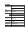
2. Specifications
MODEL
MP200
PRINT METHOD
9-pin serial impact dot matrix
PRINT DIRECTION
Bi-directional (with logical seeking)
NO. OF COLUMNS
Epson Mode : 42/35, 40/33, Star Sp200 : 42/35
Other Modes : 40/33
FONT SIZE
7 x 9, 9 x 9 dots
LINE SPACING
n/144 inch
PRINTING WIDTH
63.5mm (2.5 inch)
PRINT SPEED
5 lines/sec (at 40CPL)
INK RIBBON
EPSON ERC-38 compatible
Black, Purple, Black / Red
PAPER
Media
Roll Paper
Width
76.2mm (3.0 inch)
Diameter
DATA BUFFER
76mm (3.0 inch) max.
3-ply max. (0.2mm or 0.008” thick)
One Original and one copy
48 Kbytes
CASH DRAWER DRIVER
2 circuits (24V, 1A max)
INTERFACE OPTIONS
RS-232C Serial (25pin)
Ethernet
Centronics Parallel (36pin)
Epson TM-U200, Citizen iDP-3540, Star SP200
Copies
EMULATION
POWER SUPPLY
Type
External Adaptor
Input
120VAC, 230VAC
Output
24 Vdc/2.5A
OPERATING CONDITION
5C to 40C, 10% to 80% RH
STORAGE CONDITION
-20C to 60C, 5% to 95% RH
RELIABILITY
MCBF
18 million lines
Print head
150 million characters
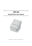
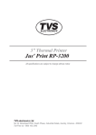
DIMENSIONS
157(W) X 245.12(D) X 153.1(H)mm
WEIGHT
5.24 lbs (2.38 kg)
Page 5
MP200 USER MANUAL
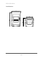
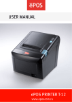
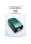
Overall dimensions
Page 6
MP200 USER MANUAL
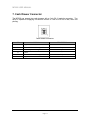
3. Self Test
While pressing the paper feed switch for more than 10 seconds after the printer in turned
on, the self test mode is initiated. The printer self test includes a listing of the current
default settings, read and write test of internal RAM, checksum test of internal program
memory, loop back detection statement, a staggered dot line, a few lines of rotating
character set, and a diagnostic report. The printer then enters into the On-Line mode.
Configuration Setup
When the paper FEED switch is pressed and released instantly as the power is applied to
the printer, the printer will print the current printer configuration settings along with the DIP
switch information. If the printer setup needs to be changed, turn the Power Off before
changing the setting.
The printer will be setup at the factory as follows;
Model:
Firmware:
Interface:
Emulation:
CR Character:
Flow Control:
Data Bits:
Parity:
Baud Rate:
CPL:
Two Color:
Auto Cutter:
Journal :
MP200 / MP200R
Ver X.XX
Serial
Epson TM-U200
CR=CR only
DTR/DSR
8 Bits
None
9600
40/33 Char/Line
Installed
Installed
Installed
Page 7
MP200 USER MANUAL
4. User Switches
Panel Switches
Paper Feed button : Pressing the PF button momentarily will advance the paper one character line
and pressing it continuously will cause a fast feed at 15 lines per second.
Power Switch
A Power switch located on the lower left side of the printer is used to turn the printer on/off.
Indicators
This section explains the different patterns signaled by the two LED indicators located on the top
cover of the MP200/MP200R.
LED1
LED2
LED3
GREEN
RED
RED
Power Off
OFF
OFF
OFF
Normal power is not supplied to the printer
Power On
Flash
ON
ON
Normal power is supplied to the printer
On line
ON
OFF
OFF
Normal error-free mode
Paper low
ON
OFF
ON
Insert new paper roll
Cover open
ON
Flash
OFF
Close cover
Paper empty
ON
ON
OFF
Flash
OFF
ON
OFF
Insert new paper roll
OFF
Impossible to recover
ON
ON
OFF
Ignored Paper Low
STATUS
Paper jam
Test mode
REMARKS
Page 8
MP200 USER MANUAL
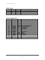
5. Command List
5.1. EMULATION EPSON TM-U200
Command
Hex Code
Description
HT
<09>H
Horizontal tab
LF
<0A>H
Print and line feed
CR
<0D>H
Carriage Return
DLE EOT
<10>H<04>H<n>
Real-time status transmission
DLE ENQ
<10>H<05>H<n>
Real-time request to printer
ESC SP
<1B>H<20>H<n>
Set right-side character spacing
ESC !
<1B>H<21>H<n>
Set print mode
ESC %
<1B>H<25>H<n>S
Select/cancel user-defined character set
ESC &
<1B>H<26>H
Define user-defined characters
ESC *
<1B>H<2A>H
Select bit-image mode
ESC -
<1B>H<2D><n>
Turn on/off underline mode
ESC 2
<1B>H<32>H
Select 1/6 inch line spacing
ESC 3
<1B>H<33>H<n>
Set line spacing
ESC <
<1B>H<3C>H
Return home
ESC =
<1B>H<3D>H<n>
Select peripheral device
ESC ?
<1B>H<3F>H<n>
Cancel user-defined characters
ESC @
<1B>H<40>H
Initialize printer
ESC D
<1B>H<44>H<n>
Set horizontal tab positions
ESC E
<1B>H<45>H<n>
Turn on/off emphasized mode
ESC G
<1B>H<47>H<n>
Turn on/off double-strike mode
ESC J
<1B>H<4A>H<n>
Print and feed paper
ESC R
<1B>H<52>H<n>
Select an international character set
ESC U
<1B>H<55>H<n>
Turns on/off unidirectional printing mode
ESC a
<1B>H<61>H<n>
Select justification
ESC c 4
<1B>H<63>H<34>H<n>
Select paper sensor to stop printing
ESC c 5
<1B>H<63>H<35>H<n>
Enable/disable panel button
ESC d
<1B>H<64>H<n>
Print and feed n lines
ESC p
<1B>H<70>H
Generate pulse
ESC t
<1B>H<74>H<n>
Select character code table
ESC {
<1B>H<7B>H<n>
Turn on/off upside-down printing mode
GS I
<1D>H<49>H<n>
Transmit printer ID
GS a
<1D>H<61>H<n>
Enable/disable Automatic Status Back
GS r
<1D>H<72>H<n>
Transmit status
Page 9
MP200 USER MANUAL
5.2. EMULATION CITIZEN iDP-3540
Command
Hex Code
Description
BEL
<07>H
Drive pulse setting command for 1st drawer
CAN
<18>H
Clear data in buffer
LF
<0A>H
Paper feed
FF
<0C>H<n>
Paper feed n lines
CR
<0D>H
Print command
SO
<0E>H
Select expanded character mode
SI
<0F>H
Select normal character mode
DC1
<11>H
Initial set command
DC2
<12>H
Inverted print mode
DC3
<13>H
Red color print command
ESC BEL
<1B>H<07>H<n>
1st drawer driver command
SUB
<1A>H
2nd drawer driver command
ESC -
<1B>H<2D>H<n>
Select underline mode
ESC *
<1B>H<2A>H<n>
Graphic command
ESC 1
<1B>H<31>H
Set 1/9 inch line feed
ESC 2
<1B>H<32>H<n>
Set 2/9 inch line feed
ESC C
<1B>H<43>H<n>
Set page length
ESC N
<1B>H<4E>H<n>
n line skip perforation command
ESC O
<1B>H<4F>H
Cancel skip perforation command
ESC P
<1B>H<50>H<n>
Select full-cut / partial-cut
ESC f
<1B>H<66>H
Form feed
FS
<1C>H
1st drawer drive command
Page 10
MP200 USER MANUAL
5.3 EMULATION STAR SP200
Command
BEL
Hex Code
<07>H
CAN
<18>H
Description
Differed drive command “A” for peripheral unit
(Default setting)
Cancel print data in buffer
LF
<0A>H
Line feed
CR
<0D>H
Line feed (same as LF)
SO
<0E>H
Select expanded character mode
SI
<0F>H
Cancel expanded character mode
FS
<1C>H
Immediate drive command “B” for peripheral unit 1
DC4
ESC BEL
n1 n2
ESC @
<14>H
<1B>H<07>H<n1>
<n2>
<1B>H<40>H
ESC M
<1B>H<4D>H
ESC R n
<1B>H<52>H<n>
Cancel expanded character mode
Adjust drive pulse width for peripheral unit
(Default setting)
Initialize printer
Select 7 x 7 (Half dots) character size
(Default setting)
Select international character set
ESC P
<1B>H<50>H
<1B>H<57>H<31>
H<1B>H<57>H<1>
<1B>H<57>H<37>
H<1B>H<57>H<0>
<1B>H<61>H<n>
ESC W 1
ESC W 0
ESC a n
Select 9 x 7 (Half dots) character size
Select expanded character mode
Cancel expanded character mode
Feed paper n lines
Page 11
MP200 USER MANUAL
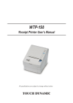
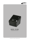
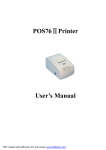
6. Interface Connectors
Ethernet
D-SUB 25 Female Serial
Centronics Parallel
Ethernet interface
PIN
SIGNAL
1
Data Out +
2
Data Out 3
GND
4
Data IN +
5
Data IN 6
N.C
7
N.C
8
N.C
I/O
Output Data +
Output Data +
Ground
Input Data +
Input Data -
Page 12
MP200 USER MANUAL
Serial interface
PIN
2
3
4, 20
6
1, 7
SIGNAL
TXD
RXD
DTR
DSR
GND
I/O
Output
Input
Output
Input
-
DESCRIPTION
Printer transmit data line RS-232C level
Printer receive data line RS-232C level
Printer handshake to host line RS-232C level
Data Send Ready
System Ground
Centronics Parallel Port
PIN
1
2-9
10
11
12
13
14
15
16
17
18
19-30
31
32
33
34
35
36
SIGNAL
STROBEDATA0-7
ACKBUSY
PE
SELECT
AUTO FEEDGROUND
GROUND
NC
LOGIC-H
GROUND
INITERRORGROUND
NC
+5V
SELLECT IN-
I/O
Input
Input
Output
Output
Output
Output
Input
Input
Output
Input
DESCRIPTION
Synchronize signal Data received
Data bit Transmitted 0 – 7
Data receiving competed
Impossible to printer data receiving
Paper empty
Printer’s status for ON/OFF line
Paper auto feed signal
System Ground
System Ground
+5V
System Ground
Initialize
Printer Error
System Ground
+5V
Printer select signal
Page 13
MP200 USER MANUAL
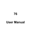
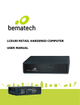
7. Cash Drawer Connector
The MP200 can operate two cash drawers with a 6 pin RJ-11 modular connector. The
driver is capable of supplying a maximum current of 1.0A for 510 ms or less, when not
printing.
Cash Drawer Connector
PIN
SIGNAL
DESCRIPTION
1
Signal GND
-
2
Drawer kick-out drive signal 1
3
Drawer open/close signal
4
+24V
5
Drawer kick-out drive signal 2
6
Signal GND
Output
Input
Output
-
Page 14
MP200 USER MANUAL
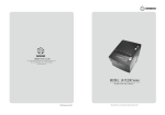
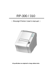
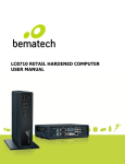
8. Electrical Specifications
The MP200 requires a power supply with the following parameters. A DC power Adapter is
included in the MP200/MP200R box.
Power Supply Voltage : 24VDC±10%
Power Supply Current : 2.5 A
Power Supply Connector
Page 15
MP200 USER MANUAL
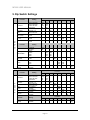
9. Dip Switch Settings
Function
Function
Emulation
CR
Character
CPL
Auto Cutter
2 Color
S
E
R
I
A
L
Journal
Setting
Epson TM-U200
Epson TM-U300
Citizen iDP3540
Star SP200
CR=CR Only
CR=CR + LF
40/33 Char/Line
42/35 Char/Line
Not Install
Install
Not Install
Install
Not Install
Install
1
2
OFF
ON
OFF
ON
OFF
OFF
ON
ON
3
4
5
6
7
8
OFF
ON
OFF
ON
OFF
ON
OFF
ON
OFF
ON
Function
Function
Setting
1
Flow Control
Baud Rate
Data Bits
Parity
Auto
Melody
DTR/DSR
Xon/Xoff
38400
19200
9600
4800
8 Bits
7 Bits
None
Odd
Even
Not Install
Installed
2
3
OFF
ON
OFF
ON
OFF
OFF
ON
ON
4
5
6
OFF
ON
OFF
ON
ON
7
8
OFF
ON
OFF
ON
OFF
ON
Function
Function
Emulation
CR
Characte
P
A
R
A
L
L
E
L
CPL
Auto
Cutter
2 Color
Journal
Setting
Epson TM-U200
Epson TM-U300
Citizen iDP3540
Star SP200
CR=CR Only
CR=CR + LF
40/33 Char/Line
42/35 Char/Line
Not Installed
Installed
Not Installed
Installed
Not Installed
Installed
1
2
OFF
OFF
ON
ON
OFF
ON
OFF
ON
3
4
5
6
7
8
OFF
ON
OFF
ON
OFF
ON
OFF
ON
OFF
ON
Function
Function
Setting
Auto
Melody
Not Install
Installed
1
2
3
4
5
6
7
8
OFF
ON
Page 16
MP200 USER MANUAL
Logic Controls, Inc.
999 S. Oyster Bay Rd
Building #104
Bethpage, NY 11714
USA
Tel: +1 516 248 0400
Fax: +1 516 495 4075
Page 17