1
User’s Manual
PRP-076N
PRP-076C
PRP-076D
Impact Dot-Matrix Printer
Specifications subject to change without notice
Table of Contents
1. General Information ………………………………………………………………..2
1.1) Models
1.2) Features
2. Quick Start…………………………………………………………………………..3
2.1) Unpacking & Parts Identification
2.2) Loading the Paper Roll and Ink Ribbon
3. Printer Interface and Connection……………………………………………………5
3.1) Connecting the Interface Cable
3.2) Connecting to a Cash Drawer
3.3) Connecting the AC Adapter
4. Configuration………………………………………………………………………..7
4.1) Printer Status
4.2) DIP Switch Settings
4.3) Printer Self Test
4.4) Hexadecimal Dumping
4.5) Driver Installation
5. Safety and Maintenance……………………………………………………………11
5.1) Safety Information
5.2) Periodical Cleaning
5.3) Preventing Paper Jams
5.4) Fixing Paper Jam
6. Appendix………………………………...………………………………………....13
- Product Specifications
- General Printer Commands
- International Character Fonts
1
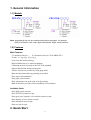
1. General Information
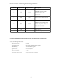
1.1) Models
Note: International font can be combined with others languages, for example
PRP-076C-BI-M-S, with cutter, Big5+International, beige, serial interface.
1.2) Features
Main Features:
-3.5 characters line/sec / 4.5 characters line/sec (32 bit ARM CPU)
-76 mm ± 5 mm Max. label width
-Low-noise dot matrix printing
-High reliability due to a stable mechanism
-Command protocol is based on the ESC/POS standard
-Support black mark anchor testing print
-Various Layouts are possible by using page mode
-Repeated operation and copy printing are possible
-Easy paper-roll installation
-Easy paper jam clearance
-Easy maintenance for tasks such as head cleaning
-Built-in interface provides control capability for cash drawer
Available fields:
-Print POS system receipts
-Print EFT POS system receipts
-Print gym, post, hospital, civil aviation system receipts
-Print inquiry, service system receipts
-Print instrument test receipts
-Print tax, tab receipts
2. Quick Start
2
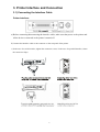
2.1) Unpacking & Parts Identification
Unpacking:
Parts Identification:
Power switch
3
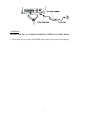
2.2) Loading the Paper Roll and Ink Ribbon
a. Make sure that the paper roll matches the printer’s specification. Do not use paper rolls that
have the paper glued to the core because the printer cannot detect the paper end correctly.
Important: The printing quality and lifespan of the printer head cannot be guaranteed if
any paper other than that recommended is used. Thus, the warranty will be void
automatically if any fault occurs due to the use of wrong paper rolls.
b. Open the top cover
Important: Do not open the printer cover when printing is in progress.
c. Install the paper roll as the picture showing direction
d. Pull the paper out of some length to outside, then close the cover.
e. Open the printer’s cover, turn the knob five or six times in the direction of the arrow, insert
the ink ribbon, and push the ribbon cassette down until it clicks.
Op e n Co ve r
4
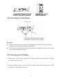
3. Printer Interface and Connection
3.1) Connecting the Interface Cable
Printer Interface:
a) Before connecting/disconnecting the interface cable, make sure that power to the printer and
all the devices connected to the printer is turned off.
b) Connect the interface cable to the connector on the rear panel of the printer.
c) In the case of a serial interface, tighten the connector screws. In the case of a parallel interface, fasten
the connector clasps.
5
3.2) Connecting to a Cash Drawer
Important:
z Make sure that the printer is turned off and unplugged from the AC outlet and that the
computer is turned off before making connections.
z Do not connect a telephone line into the peripheral drive connector. Failure to observe this
may result in damage to the printer.
3.3) Connecting the AC Adapter
a. Connect the AC power cord to the inlet of AC adapter, and then connect the power cord plug
to a suitable electrical outlet.
b. Connect the adapter cable to power connector of printer; make sure the printer power switch
is OFF before making any connections.
6
CAUTION:
DO NOT USE ANY AC POWER ADAPTERS OTHER THAN SPECIFIED.
c. Turn on the power switch; the POWER lamp on the control panel will light up.
7
4. Configuration
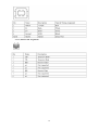
Printer Control Panel & Status Indication
4.1) Printer Status
z
Power (POWER) LED: Green
On: Power is on.
Off: Power is off.
z
Error (ERROR) LED: Red
On: Offline (except during paper feeding using the FEED button and test printing,
and the error state.)
Off: Normal condition.
z
Paper roll end (PAPER) LED: Red
Flash: The paper roll end is detected.
Off: Paper is loaded (Normal condition).
z
FEED (Button)
Press the FEED button to feed roll paper.
Press the FEED button for 1 second and the roll paper will be fed continuously.
8
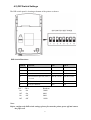
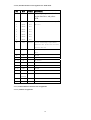
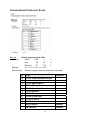
4.2) DIP Switch Settings
The DIP switch panel is locating at bottom of the printer as shown:
DIP Switch Functions:
Switch
Function
ON
OFF
1
Black mark mode
No
Yes
2
Select Cutter
No
Yes
3
Cut mode
Partial
Full
4
Select characters per line (CPL) 7
40CPL/33CPL
42CPL/35CPL
x9/9x9
5
Unidirectional
No
Yes
6
Two-byte character
Yes
No
SW 7
On
Off
On
Off
SW 8
On
On
Off
Off
Baudrate
38400
4800
9600
19200
Note:
Before configure the DIP switch settings, please first turn the printer power off and remove
the paper roll.
9
(*) Baud Rate is only available for serial interface models.
4.3) Printer Self Test
This is to test whether the printer is working properly or not and also checks the printing
quality, firmware version, and DIP switch settings
1. Hold the FEED button first and then turn on the power at the same time, release the button
after around 2 seconds.
2. If the printer is working properly, it should then automatically print the self-testing result
that indicating the firmware version number, printer connection type, English alphanumeric
characters, and few Taiwanese fonts.
3. The test print will be ended with the following message:
*** COMPLETED ***
Note: The above procedure does not test parallel or serial, USB, Ethernet ports. Please use
communication utility such as Windows HyperTerminal to test the printer connection.
4.4) Hexadecimal Dumping
1) Hexadecimal Dumping
This function prints the data transmitted from the host computer in hexadecimal numbers
and in its corresponding characters.
2) Starting hexadecimal dumping
Turn the power on while pressing the FEED button or executing GS ( A command). The
printer first prints “Hexadecimal Dump” on paper roll and prints the received print data in
hexadecimal numbers and in its corresponding characters.
NOTES: 1. When using the hexadecimal dump mode, please set the SW-4 of the DIP switch
to OFF.
2. During hexadecimal dumping, any commands do not function.
3. If no characters correspond to the data received, the printer prints “."。
3) Ending hexadecimal dumping
Hexadecimal dumping ends by turning the power off, or pressing the FEED button three
times.
<Printing example>
10
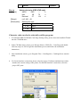
4.5) Driver Installation
1. To install the PRP-076 driver, please insert the bundled CD disk into the CD-ROM drive.
2. In the CD-Rom menu, please go to Receipt Printer > PRP-076 folder and double click the
SetupEn.exe file to begin the driver installation process and follow the installation
instructions.
3. Please choose the OS that matches with your computer system and press Next.
4. Please select PRP-076 Series for Install Module. For Printer Port Setting, if you are
connecting the printer to PC COM ports via RS-232 connection, the FlowControl must
be set to Hardware. Press Finish when you done all the setting to end installation.
11
5. Safety and Maintenance
5.1) Safety Information
1.
2.
3.
4.
5.
6.
7.
Do not touch the HEAD of printer with anything.
Do not touch the cutter blade.
Only use the power supply that is come along with the printer.
Do not bend the power cord excessively or place any heavy objects onto it.
When connecting or disconnecting the plug, always hold the plug – not the cord.
Keep the distance out of children’s reach.
Use only approved accessories and do not try to disassemble, repair or remodel it for
yourself.
8. Do not let water or other foreign objects in the printer.
9. Install the printer on the stable surface. Choose a firm, level surface where the printer will
not be exposed to vibration.
10. Do not use the printer when it is out of order. This can cause a fire or an electrocution.
11. Do not connect a telephone line into the peripheral drive connector.
12. We recommend that you unplug the printer from the power outlet whenever you do not
plan to use it for long periods.
5.2) Periodical Cleaning
Printed characters may become partially unclear due to accumulated paper dust and dirt. To prevent
12
such a problem, paper dust collected in the paper holder and paper transport section and on the surface
of the printer head must be removed periodically. Such cleaning is recommended to be carried out once
six month or one million lines.
Cleaning the Paper Holder
Use a soft cloth to remove paper dust from the paper holder and paper transport section.
5.3) Preventing Paper Jams
The paper should not be touched during printing.
Shift the paper during paper ejection may cause a
feed failure or paper jam.
5.4) Fixing Paper Jam
The Status LED (Red) on the printer control panel will flash with beeps if paper is jammed.
Please follow the below instruction to remove paper jam.
(a) Switch the printer power off.
(b) Open the printer cover.
(c) If the printer cover opens, removed the jammed paper gently (take care not to touch the
printer head.) And reinstall the paper roll.
Caution:
Since working on the cutter may be dangerous, be sure to turn off the printer first.
Note:
Do not apply extreme force to open the front cover to prevent damages to the cutter. If the
front cover will not open properly, please contact your dealer.
(d) Return the cutter to its home-position and release or clean out the jammed paper in inside
the front cover. Open the top cover, and then reinstall paper roll.
13
6. Appendix
Product Specifications
1.1) Printing Specifications
1) Printing method:
9 pins Impact Dot Matrix
2) Print density:
400 dpi (half dot)
385 dpi (half dot)
3) Printing direction:
Bidirectional, adjustable by dipswitch
4) Printing width:
42CPL ( 7 x 9 ) / 35CPL ( 9 x 9 )
40CPL ( 7 x 9 ) / 33CPL ( 9 x 9 )
5) Printing speed:
4.5 characters line/sec
6) Paper feed speed:
120 mm/sec
NOTE: There may be variations in printing after switching the mode of the printing speed. To prevent this
for logo printing with ESC command, using a downloaded bit image is recommended. Change in printing speed
does not occur during down loaded bit image printing.
Printing speed may be slower depending on the data
transmission speed and the combination of control commands. Low transmission speed may cause intermittent
printing. It is recommended to transmit data to the printer as quickly as possible.
1.2) Print font
1)
ASCII code:
7 x 9 dots, 1.2 (W) x 3.1 (H) mm
9 x 9 dots, 1.6 (W) x 3.1 (H) mm
2)
Graphic font:
16 x 16 dots, 2.54 (W) x 2.82 (H) mm
1.3) Mechanical Specification
1)
Weight:
2) Dimension:
1600g
/
1680g (PRP-076D)
260 (L) x 155 (W) x 130 (H) mm
1.4) Paper Specification
1) Paper type:
Continuous multipart, original plus carbonless copies
2) Form:
Paper roll
3) Paper width:
75 ± 0.5 mm
4) Paper roll size:
Roll diameter:
Maximum 75 mm
Minimum 12 mm
1.5) Interface
1) Serial port:
Dsub 25 pin female connector, 4800,9600,19200 or 38400 bps
baud-rate, none parity, 8 data bits, and 1 stop bit, supports RTS/CTS &
14
XON/XOFF protocol
2) Parallel port:
36 pin Centronics connector. 8 bits parallel, supports BUSY/nAck
protocol
3) USB port:
USB1.0
4)
Transmission speed: 10M (Max)
Ethernet port:
Communication protocol: TCP/IP protocol
Connector: 10 Base-T RJ-45 connector
5) Cash drawer port:
DC 24V/1A, 6 wires RJ-11 socket
1.6) Electrical Characteristics
1) Supply voltage:
Input: AC 110V/220V, 50~60Hz
Output: DC 24V/2.5A
1.7) Reliability
MCBF:
10,000,000 lines
(This is an average failure interval based on failures relating to
wear out and random failures up to the life of 15 million lines.)
1.8) Environmental Conditions
1) Temperature:
Operating: 0 to 50C (41 to 113F)
Storage: -10 to 60C (14 to 122F) (except paper)
2) Humidity:
Operating: 10 to 80% RH
Storage: 10 to 90% RH (except for paper)
NOTE: If the printer is not used for a long time with paper installed, some part of the printing may be light
due to the deformation of the paper. If the printer is not used for a long time with paper installed, be
sure to feed paper approximately 30 mm before printing
.
3) Acoustic noise (Operating):
When using auto cutter Approximately 50 dB
(Bystander position) When not using auto cutter: Approximately 40 dB
(Bystander position)
1.9) Installation
The PRP-076 series printer must be installed horizontally. (Vibration during paper cutting and using a drawer
should be considered.
Take measures to prevent the printer from moving. Affixing tapes are provided as an
option.) An optional hanging bracket can attach the printer to a wall. (Following the procedures describes in the
installation manual, install the wall mount and change the location of the paper roll near-end sensor, then install
15
the paper roll stopper and other parts.)
2. CONFIGURATION
2.1) Interface
2.1.1) RS-232 serial interface
2.1.1.1) RS-232 Specifications
Data transmission:
Serial
Synchronization:
Asynchronous
Handshaking:
DTR/DSR or XON/XOFF control
Signal levels:
MARK = -3 to -15 V: Logic "1"/ OFF
SPACE = +3 to +15 V: Logic "0"/ ON
Baud rate:
9600, 19200 bps
Data word length:
8 bits
Parity Settings:
None
Stop bits:
1 or more
Connector (printer side):
Female DSUB-25 pin connector
NOTES: The data word length, baud rate, and parity depend on the DIP switch settings.
The stop bit for the printer side is fixed to 1.
2.1.1.2 Serial interface connection example
Printer Side DB-25
POS RS-232 Connection DB9
NOTES: Set the handshaking so that the transmit data can be received.
Transmit data to the printer after turning on the power and initializing the printer.
16
Interface connector terminal assignments and signal functions
Pin number
Signal name
Signal Source
Description
When using XON/XOFF
2
TXD
Printer
handshake protocol, printer
transmits control code
XON/XOFF
3
RXD
Host
Printer receives data from host
Indicates printer current status,
4
RTS
Printer
whether the printer is Busy or
Ready to receive data
7
GND
——
20
DTR
Printer
Signal ground
Same as RTS (pin 4)。
2.1.2) IEEE 1284 Bidirectional Parallel Interface (Parallel Interface Specifications)
2.1.2.1) Parallel Specifications
Data transmission:
Parallel
Synchronization:
Externally supplied nStrobe signals
Handshaking:
nAck and Busy signals
Signal levels:
TTL compatible
Data word length:
Connector (printer side):
8 bits
36 pins Centronics connector
17
2.1.2.2) Parallel Interface Pin Assignments for Each Mode
Pin
Mode
Source
Description
1
/STB
Host
The computer presents the data
on the data lines, and pulses
STB
2
DATA0
Host
Indicates the 1st data bit through 8th
3
DATA1
Host
data bit
4
DATA2
Host
5
DATA3
Host
6
DATA4
Host
7
DATA5
Host
8
DATA6
Host
9
DATA7
Host
10
nAck
Printer
Printer acknowledge signal which
indicates that printer has received
previous data bit
11
BUSY
Printer
Printer is busy and cannot receive
data
12
GND
——
13
Select
Printer
14,15
NC
——
No Connect
16,17
GND
——
Ground
18
Logic-H
Printer
19~30
GND
——
Ground
31
NC
——
No Connect
32
NError
Printer
Ground
High electric potential
High electric potential
Printer Error Signal
(nFault)
33
GND
——
Ground
34~36
NC
——
No Connect
2.1.3) USB and Ethernet Interface Pin Assignments
2.1.3.1) USB Pin Assignments
18
2.1.3.1) Ethernet Pin Assignments
19
2.2 Connectors
2.2.1 Interface Connectors
Refer to Interface explain.
2.2.2 Power Supply Connector
This connector is used to connect the printer to an external power source.
Power Supply Connector Pin Assignments
Pin Number
Signal Name
1
+24 VDC
2
GND
3
NC
Shell
Frame GND
2.2.3 Drawer Kick-out Connector (Modular Connector)
The pulse specified by ESC p or DLE DC4 is output to this connector. The host can confirm the status of the
input signal by using the DLE EOT, GS a, or GS r commands.
1) Pin assignments: Refer to Table
2) Connector model: Printer side: MOLEX 52065-6615 or RJ11 telephone jack
User side: 6-position 6-contact (RJ11 telephone jack)
Drawer Kick-out Connector Pin Assignments
Pin Number
Signal Name
1
NC
2
Frame GND
3
NC
4
Drawer kick-out drive signal
5
NC
6
NC
Direction
Output
Output
1) Drawer kick-out drive signal
Output signal:
Output voltage: Approximately 24 V
Output current: 1A or less
20
General Printer Commands
COMMANDS LIST
Command
Name
LF
Print and line feed
CR
Print and carriage return
ESC SP n
Set right-side character spacing
ESC ! n
Select print mode(s)
ESC % n
Select/cancel user-defined character set
ESC &
Define user-defined characters
ESC * m nL nH d1…dk
Select bit-image mode
ESC – n
Turn underline mode on/off
ESC 2
Select default line spacing
ESC 3 n
Set line spacing
ESC ? n
Cancel user-defined characters
ESC @
Initialize printer
ESC D [n]k NUL
Set horizontal tab positions
HT n
Print horizontal tab processing
ESC J n
Print and feed paper n x 0.176 mm
ESC K n
Print and reverse paper n x 0.176 mm
ESC R n
Select an international character set
ESC U n
Enable/Disable single print direction
ESC c 5 n
Enable/disable panel buttons
ESC d n
Print and feed n lines
ESC e n
Print and reverse n lines
ESC p m t1 t2
Generate cash drawer pulse
GS ( A pL pH n m
Enter hexadecimal dump test mode
GS V m [n]
Select cut mode and cut paper
GS z 0 t1 t2
Set online recovery waiting time
FS ! n
Set print mode(s) for Kanji characters
FS &
Enter Kanji character mode
FS .
Exit Kanji character mode
FS 2 c1 c2 d1…dk
Define user-defined Kanji characters
FS ? c1 c2
Cancel user-defined Kanji characters
FS S n1 n2
Set left- and right-side Kanji character spacing
FS W n
Turn quadruple-size mode on/off for Kanji characters
GS ( F pL pH a m nL nH
Set relative black mark anchor position
GS FF
Set black mark anchor to start of printing position
Esc r n
Select print color (PRP-076D only)
21
International Character Fonts
Esc t n
[format]
Select character code table
ASCII
ESC
t
n
Hex
1B
74
n
Decimal
27
116
n
[Range]
0 <= n <= 5, 16 <= n <= 19
[Description]
Selects a page n from the character code table
N
Page
comment
0
PC 437 (USA,Standard Europe)
1
Katakana (Japan)
2
PC 850 (Multilingual)
3
PC 860 (Portuguese)
4
PC 863 (Canadian-French)
5
PC 865 (Nordic)
16
WPC 1252
17
PC 866 (Cyrillic #2)
18
PC 852 (Latin 2)
19
PC 858
Big 5 Chinese
Optional
GB Chinese
Optional
22
Korean
Optional
Esc r n
[format]
Select print color (PRP-076D only)
ASCII
ESC
t
n
Hex
1B
72
n
Decimal
27
114
n
[Range]
n=0, 48,1 ,49
[Description]
Select print color
n
Select Color
0, 48
Black
1, 49
Red
Character code can also be selected by utility program:
1. To install the PRP-076 Default Code Page Setting utility, please insert the bundled CD disk
into the CD-ROM drive.
2. In the CD-Rom menu, please go to Receipt Printer > PRP-076 > Code Page and double
click the setup.exe file to begin the installation process and follow the installation
instructions.
3. After installation is done, go to Program Files > CodePageSet > CodePageSet to start the
utility.
4.
For Serial interface connection, please select the proper COM port and baud rate which
matches the current setting of the printer. For Parallel interface connection, select the
proper LPT ports.
23
Optional multilingual character model supports printing with one of the following characters:
a. B - Traditional Chinese (Big 5)
b. G - Simplify Chinese (GB)
c. K - Korean
d. J- Japanese Kanji (JIS)
To enable/disable the multilingual character code use the following commands: (*)
FS “&”
[Format]
Select Multilingual Character Mode ON
ASCII
FS
&
Hex
1C
26
Decimal
28
38
[Description] Enable multilingual character mode
----------------------------------------------------------------------FS “.”
[Format]
Select Multilingual Character Mode OFF
ASCII
FS
.
Hex
1C
2E
Decimal
28
46
[Description] Disable multilingual character mode
(*)Note: This command enable/disable the specific language according to the model (B, G, K
or J)
International Character Code:
Country
ASCII code (Hexadecimal)
23
24 40 5B
5C
5D
USA
#
$
@
France
#
$
Germany
#
UK
7B
7C
7D
7E
[
\
]
^
`
{
¦
}
~
à
°
ç
§
^
`
é
ù
è
¨
$
§
Ä
Ö
Ü
^
`
ä
ö
ü
ß
£
$
@
[
\
]
^
`
{
¦
}
~
Denmark I
#
$
@
Æ
Ø
Å
^
`
æ
ø
å
~
Sweden
#
¤
É
Ä
Ö
Å
Ü
é
ä
ö
å
ü
24
5E 60
Italy
#
$
@
°
\
é
^
ù
à
ò
è
ì
Spain I
Pt
$
@
ì
Ň
¿
^
`
¨
ñ
}
~
Japan
#
$
@
[
¥
]
^
`
{
¦
}
~
Norway
#
¤
É
Æ
Ø
Å
Ü
é
æ
ø
å
ü
Denmark II
#
$
É
Æ
Ø
Å
Ü
é
æ
ø
å
ü
25