1
ePOS-Device XML
User’s Manual
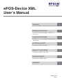
Overview
Describes the features and development environment.
Building Environment
Describes environment building for ePOS-Device
Service I/F.
Programming Guide
Describes how to write programs in Web application
development.
ePOS-Device XML
Describes the ePOS-Device XML.
Device Control Script
Describes the device control script.
Sample Program
Describes the sample program.
Appendix
M00055604
Rev.E
Cautions
• No part of this document may be reproduced, stored in a retrieval system, or transmitted in any form or
by any means, electronic, mechanical, photocopying, recording, or otherwise, without the prior written
permission of Seiko Epson Corporation.
• The contents of this document are subject to change without notice. Please contact us for the latest
information.
• While every precaution has taken in the preparation of this document, Seiko Epson Corporation assumes
no responsibility for errors or omissions.
• Neither is any liability assumed for damages resulting from the use of the information contained herein.
• Neither Seiko Epson Corporation nor its affiliates shall be liable to the purchaser of this product or third
parties for damages, losses, costs, or expenses incurred by the purchaser or third parties as a result of:
accident, misuse, or abuse of this product or unauthorized modifications, repairs, or alterations to this
product, or (excluding the U.S.) failure to strictly comply with Seiko Epson Corporation’s operating and
maintenance instructions.
• Seiko Epson Corporation shall not be liable against any damages or problems arising from the use of any
options or any consumable products other than those designated as Original EPSON Products or EPSON
Approved Products by Seiko Epson Corporation.
Trademarks
EPSON, EXCEED YOUR VISION, and ESC/POS are registered trademarks of Seiko Epson Corporation in Japan
and other countries/regions.
Windows and Internet Explorer are either registered trademarks or trademarks of Microsoft Corporation in
the United States and other countries.
AndroidTM and Google ChromeTM are either registered trademarks or trademarks of Google Inc. in the
United States and other countries.
Apple, Mac, Mac OS and Xcode iPhone, iPad are either registered trademarks or trademarks of
Apple Inc. in the United States and other countries.
iOS is registered trademarks or trademarks of Cisco in the United States and other countries.
Flash, FlexTM are either registered trademarks or trademarks of Adobe Systems Incorporated in the United
States and other countries.
JavaTM is a registered trademark of Oracle Corporation, its subsidiaries, and affiliates in the U.S. and other
countries.
Eclipse is a trademark or registered trademark of Eclipse Foundation, Inc.
ESC/POS® Command System
EPSON has been taking industry’s initiatives with its own POS printer command system (ESC/POS). ESC/POS
has a large number of commands including patented ones. Its high scalability enables users to build versatile POS systems. The system is compatible with all types of EPSON POS printers (excluding the TM-C100) and
displays. Moreover, its flexibility makes it easy to upgrade the future. The functionality and the user-friendliness is valued around the world.
© Seiko Epson Corporation 2014. All rights reserved.
2
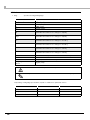
For Safety
Key to Symbols
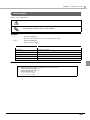
The symbols in this manual are identified by their level of importance, as defined below. Read the following
carefully before handling the product.
Provides information that must be observed to avoid damage to your equipment or a
malfunction.
Provides important information and useful tips.
Restriction of Use
When this product is used for applications requiring high reliability/safety such as transportation devices
related to aviation, rail, marine, automotive etc.; disaster prevention devices; various safety devices etc; or
functional/precision devices etc, you should use this product only after giving consideration to including failsafes and redundancies into your design to maintain safety and total system reliability. Because this product
was not intended for use in applications requiring extremely high reliability/safety such as aerospace
equipment, main communication equipment, nuclear power control equipment, or medical equipment
related to direct medical care etc, please make your own judgment on this product’s suitability after a full
evaluation.
3
About this Manual
Aim of the Manual
This manual is aimed to provide developers with information required for developing and designing
applications using ePOS-Device XML.
The TM-Intelligent series in this manual is a generic term for the TM-DT series and TM-i series.
The TM-DT series is a generic term for the following printers.
TM-T88V-DT
TM-T70II-DT
TM-H6000IV-DT
The TM-i series is a generic term for the following printers.
TM-T88V-i (TM-i firmware Ver.4.0 or later) TM-T70-i (TM-i firmware Ver.4.0 or later)
TM-T20II-i
TM-T82II-i
Manual Content
The manual is made up of the following sections:
Chapter 1
Overview
Chapter 2
Building Environment
Chapter 3
Programming Guide
Chapter 4
ePOS-Device XML
Chapter 5
Device Control Script
Chapter 6
Sample Program
Appendix
List of KeyCode
Printer specifications
Paper setting function of TM-L90
4
Contents
■ For Safety...............................................................................................................................3
Key to Symbols ....................................................................................................................................... 3
■ Restriction of Use ..................................................................................................................3
■ About this Manual ................................................................................................................4
Aim of the Manual................................................................................................................................. 4
Manual Content .................................................................................................................................... 4
■ Contents ................................................................................................................................5
Overview ......................................................................................11
■ ePOS-Device XML...............................................................................................................11
Features ................................................................................................................................................ 12
System Configuration Example .......................................................................................................... 12
How to Use the Communication Box ................................................................................................ 13
■ Operating Environment ......................................................................................................16
Application Environment .................................................................................................................... 16
Application Terminal ........................................................................................................................... 16
TM-Intelligent ........................................................................................................................................ 16
TM Printer .............................................................................................................................................. 17
Customer Display................................................................................................................................. 17
Peripheral Device ................................................................................................................................ 18
■ Contents in the Package ...................................................................................................19
Manual.................................................................................................................................................. 19
Sample Program .................................................................................................................................. 19
Download ............................................................................................................................................. 19
■ Restrictions ..........................................................................................................................20
Building Environment ...................................................................21
■ Updating the ePOS-Device ...............................................................................................21
TM-DT Series .......................................................................................................................................... 21
TM-i Series.............................................................................................................................................. 22
■ Workflow ..............................................................................................................................23
TM-DT Series .......................................................................................................................................... 23
TM-i Series.............................................................................................................................................. 24
■ Registration of Device Control Script (TM-DT Series).......................................................25
■ Registration of Device ........................................................................................................27
TM-DT Series .......................................................................................................................................... 27
TM-i Series.............................................................................................................................................. 30
5
Programming Guide ....................................................................33
■ Programming Flow ............................................................................................................. 33
If Reconnecting to the TM-Intelligent when the Network was Cut Off ..........................................34
Programming flow for the Communication Box ...............................................................................35
■ Service Interface Specifications....................................................................................... 38
Format ...................................................................................................................................................38
■ Communication Data Example ........................................................................................ 39
Communication Box Message Example ...........................................................................................42
■ Array of <data> elements in <device_data> message ................................................. 44
ePOS-Device XML ........................................................................45
■ ePOS-Device XML List ........................................................................................................ 45
Message ................................................................................................................................................45
Message Data for Communication Box ............................................................................................46
Message Data for Each Device .........................................................................................................46
■ Messages ............................................................................................................................ 49
<connect> ............................................................................................................................................49
<reconnect> .........................................................................................................................................50
<disconnect>........................................................................................................................................51
<admin_info> ........................................................................................................................................52
<open_commbox> ..............................................................................................................................54
<close_commbox> ..............................................................................................................................56
<commbox_data> ...............................................................................................................................57
<open_device> ....................................................................................................................................58
<close_device> ....................................................................................................................................60
<device_data>.....................................................................................................................................62
<error> ...................................................................................................................................................63
■ Message Data for Communication Box........................................................................... 64
<type>getcommhistory</type> .........................................................................................................64
<type>send</type> .............................................................................................................................66
<type>onreceive</type>....................................................................................................................67
■ Message Data for Device Hub Terminal .......................................................................... 68
<type>shutdown</type>.....................................................................................................................68
<type>onshutdown</type> ................................................................................................................68
■ Message Data for the Barcode Scanner ......................................................................... 69
<type>ondata</type> ........................................................................................................................69
■ Message Data for Printers ................................................................................................. 70
<type>print</type>..............................................................................................................................70
<type>onxmlresult</type> ..................................................................................................................70
■ Message Data for Hybrid Printers ..................................................................................... 71
<type>lock</type> ..............................................................................................................................71
<type>unlock</type> ..........................................................................................................................71
<type>print</type>..............................................................................................................................72
<type>onxmlresult</type> ..................................................................................................................72
<type>slipprint</type> ........................................................................................................................73
6
<type>slipcancel</type> ................................................................................................................... 73
<type>endorseprint</type>............................................................................................................... 74
<type>endorsecancel</type> .......................................................................................................... 74
<type>micrread</type> ..................................................................................................................... 75
<type>micrcancel</type> ................................................................................................................. 76
<type>micreject</type> .................................................................................................................... 76
<type>micrcleaning</type> .............................................................................................................. 76
<type>onreceive</type> ................................................................................................................... 77
■ Printer Control XML .............................................................................................................79
<epos-print> ......................................................................................................................................... 79
<response> ........................................................................................................................................... 81
<text> .................................................................................................................................................... 84
<feed>................................................................................................................................................... 90
<image> ............................................................................................................................................... 92
<logo> ................................................................................................................................................... 94
<barcode> ........................................................................................................................................... 95
<symbol> .............................................................................................................................................. 99
<hline>................................................................................................................................................. 104
<vline-begin> ..................................................................................................................................... 105
<vline-end>......................................................................................................................................... 106
<page> ............................................................................................................................................... 107
<area> ................................................................................................................................................ 108
<direction> ......................................................................................................................................... 109
<position> ........................................................................................................................................... 110
<line>................................................................................................................................................... 111
<rectangle>........................................................................................................................................ 112
<cut> ................................................................................................................................................... 113
<pulse>................................................................................................................................................ 114
<sound> .............................................................................................................................................. 115
<command> ...................................................................................................................................... 117
<layout> .............................................................................................................................................. 118
<recovery> ......................................................................................................................................... 121
<reset> ................................................................................................................................................ 121
■ Message Data for the Customer Display........................................................................122
<type>display</type>....................................................................................................................... 122
<type>onxmlresult</type> ............................................................................................................... 123
■ Customer Display Control XML........................................................................................124
<epos-display>................................................................................................................................... 124
<response> ......................................................................................................................................... 125
<window> ........................................................................................................................................... 126
<text> .................................................................................................................................................. 128
<cursor> .............................................................................................................................................. 129
<blink>................................................................................................................................................. 130
<brightness> ....................................................................................................................................... 131
<marquee>......................................................................................................................................... 132
<clock> ............................................................................................................................................... 133
<clear>................................................................................................................................................ 133
<reset> ................................................................................................................................................ 133
<command> ...................................................................................................................................... 133
7
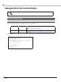
■ Message Data for the POS Keyboard............................................................................. 134
<type>onkeypress</type> ................................................................................................................134
<type>setprefix</type> .....................................................................................................................135
<type>onstring</type> ......................................................................................................................136
<type>setMSRPrefix</type> ..............................................................................................................137
<type>ondata</type> ......................................................................................................................138
■ Message Data for the Serial Device............................................................................... 139
<type>sendcommand</type>.........................................................................................................139
<type>oncommandreply</type> ....................................................................................................140
Device Control Script ................................................................ 141
■ Programming.................................................................................................................... 141
Using Device Control Script ...............................................................................................................141
Configuration of Device Control Script............................................................................................142
■ List of Device Control Script API...................................................................................... 144
ClientConnection object ..................................................................................................................144
DeviceConnection object ................................................................................................................144
Device Control Script Name object.................................................................................................144
■ ClientConnection Object ................................................................................................ 145
send .....................................................................................................................................................145
■ DeviceConnection Object.............................................................................................. 146
send .....................................................................................................................................................146
■ Device Control Script Name Object .............................................................................. 147
onDeviceData event (Input Device That Can Run with a HID Driver) .........................................147
onDeviceData event (Serial Communication Device) .................................................................147
Any event ............................................................................................................................................148
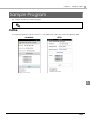
Sample Program ........................................................................ 149
■ Outline............................................................................................................................... 149
■ Building Environment for Android ................................................................................... 150
Environment ........................................................................................................................................150
Flow of environment construction for TM-DT Series ........................................................................151
Flow of environment construction for TM-i Series ............................................................................153
Installing Java SE Development Kit...................................................................................................155
Setting Up Eclipse ...............................................................................................................................157
Setting Up Android SDK Manager ....................................................................................................159
Installing ADT Plugin............................................................................................................................164
Importing the Sample Program ........................................................................................................168
Setting the Barcode Scanner............................................................................................................170
■ Building Environment for iOS ........................................................................................... 172
Environment ........................................................................................................................................172
Flow of environment construction for TM-DT Series ........................................................................173
Flow of environment construction for TM-i Series ............................................................................174
Setting the Barcode Scanner............................................................................................................175
Setting the Sample Program .............................................................................................................177
8
■ Executing Sample Program............................................................................................. 178
Androiod..............................................................................................................................................178
■ How to Use the Sample Program .................................................................................... 183
Appendix.................................................................................... 185
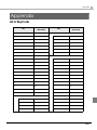
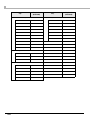
■ List of KeyCode................................................................................................................. 185
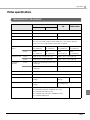
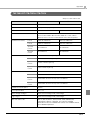
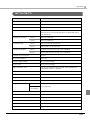
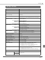
■ Printer specifications........................................................................................................ 187
TM-H6000IV-DT/ TM-H6000IV ..............................................................................................................187
TM-T70II-DT/ TM-T70II ...........................................................................................................................189
TM-T88V-DT/ TM-T88V-i/ TM-T88V........................................................................................................191
TM-T20II-i...............................................................................................................................................193
TM-T70-i/ TM-T70 ..................................................................................................................................195
TM-T82II-i/ TM-T82II ...............................................................................................................................197
TM-L90 ..................................................................................................................................................199
TM-P60II ................................................................................................................................................201
TM-P60II with Peeler ............................................................................................................................203
TM-P80..................................................................................................................................................205
TM-T20 ..................................................................................................................................................207
TM-T20II.................................................................................................................................................209
TM-T88IV ...............................................................................................................................................211
TM-T90 ..................................................................................................................................................213
TM-U220 ...............................................................................................................................................215
■ Paper setting function of TM-L90..................................................................................... 217
Setting Paper Width ...........................................................................................................................217
Automatic setting of paper layout...................................................................................................217
9
10
Chapter 1
Overview
Overview
This chapter describes the features of and the specifications for ePOS-Device XML.
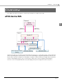
ePOS-Device XML
Terminal
Native
Application
1
Response
(XML format)
Request
(XML format)
TM-DT
Socket I/F
ePOS-Device Service I/F
Request
Response
/Event
Device Control Script
Local Printer
Customer Display
Serial Communication
Device
Key Input Device
Network Printer
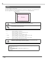
ePOS-Device XML is a command system that defines the function to control various types of POS peripheral
devices (including this product's printer) connected to TM-Intelligent using XML. Application in devices such
as personal computers, smartphones, and tablet computers creates a request message in XML format and
send it to TM-Intelligent using socket communication. ePOS-Device Service installed in TM-Intelligent
executes control over peripheral devices by interrupting a request message and returns a response.
11
Features
❏ No need to prepare any device (such as a PC) to act as a controller to control the peripheral devices.
❏ Devices that run with the OS-standard driver can be used with a device control script without any drivers
installed.
❏ Accessing a device automatically locks the device exclusively.
Even if accessed from multiple terminals simultaneously, the device is not under multiple controls. When
the terminal that has controlled the device releases the device, the device becomes controllable from
another terminal.
❏ If the network is cut off, you can easily re-establish the connection.
❏ Data can be sent and received between web applications.
For details, refer to How to Use the Communication Box(p.13).
❏ You can shut down the TM-DT from the application. * (message data for device hub terminal)
* TM-DT series is supported only.
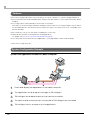
System Configuration Example
System with Application Installed in Tablet Computer
1
2
3
4
5
12
Place and display the application in the tablet computer.
The application sends a request message to TM-Intelligent.
TM-Intelligent sends data to devices that can be controlled.
The devices and network printers connected to TM-Intelligent are controlled.
TM-Intelligent returns a response to the application.
Chapter 1
Overview
How to Use the Communication Box
The Communication Box is a virtual data space that is provided by the ePOS-Device Service I/F for sending
and receiving data between applications. It is provided in ePOS-Device Ver. 2.5 and later.
The ePOS-Device is providing a virtual space and structure for sending and receiving data
between applications. Create the data to be sent and received according to your application's
specifications.
1
App1
App2
The Communication Box can be used in the following ways.
Using a tablet terminal as a POS display terminal
Displaying digital signage
Using a tablet terminal as an entry terminal
13
Example of data processing using the Communication Box
App1
App2
1
2
3
4
5
6
14
The TM-Intelligent receives the barcode data scanned by the scanner.
The ePOS-Device Service I/F notifies App2 of the barcode data.
App2 acquires the barcode data and converts it to POS data.
App2 sends the display data to the Communication Box of the ePOS-Device
Service I/F.
The ePOS-Device Service I/F notifies App1 that the display data is stored in the
Communication Box.
App1 acquires the display data stored in the Communication Box.
Chapter 1
Overview
Structure of the Communication Box
<MemberID>
-App1
-App2
<MemberID>
-App1
App1
<MemberID>
-App2
1
App2
The ePOS-Device Service I/F manages Communication Boxes with Box IDs (BoxID in the figure above).
Data can be sent and received between applications belonging to the Communication Box.
In the figure above, applications App1 and App2 can send and receive data with one another using the
BoxID:1 Communication Box.
Specifications of the Communication Box
Maximum number of Communication Boxes that can be created
20
Maximum number of applications that can belong to one Communication Box
20
Space of transfer history that one Communication Box can maintain
10240 Byte
Size of data that can be sent at one time
1024 Byte
15
Operating Environment
Application Environment
Environment that allows socket communication and handling of XML documents
❏ OS Examples: iOS / Android / Windows / Linux / MacOS
Application Terminal
Devices that allow socket communication as connected to a network
(Example: Smartphones, tablet computers, personal computers)
TM-Intelligent
TM-DT Series
❏ TM-T88V-DT
❏ TM-T70II-DT
❏ TM-H6000IV-DT
TM-i Series
❏ TM-T88V-i (TM-i firmware Ver.4.0 or later)
❏ TM-T70-i (TM-i firmware Ver.4.0 or later)
❏ TM-T20II-i
❏ TM-T82II-i
TM-i Firmware Ver.4.0 is compatible with ePOS-Device Ver.2.5.
16
Chapter 1
Overview
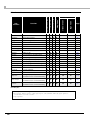
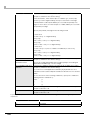
TM Printer
Besides a TM-Intelligent printer, the TM printers below can be controlled.
TM Printer
TM-DT Series
TM-i Series
TM-T20II-i
-
✔
TM-T70-i (TM-i firmware Ver.4.0 or later)
-
✔
TM-T82II-i
-
✔
TM-T88V-i (TM-i firmware Ver.4.0 or later)
-
✔
TM-H6000IV
✔
-
TM-L90
✔
✔
TM-P60II
✔
✔
TM-P60II Peeler
✔
✔
TM-P80
-
✔
TM-T20
✔
✔
TM-T20II
-
✔
TM-T70
✔
✔
TM-T70II
✔
✔
TM-T82II
-
✔
TM-T88IV
-
✔
TM-T88V
✔
✔
TM-T90
✔
✔
TM-U220
✔
✔
1
TM-T20II-i cannot control other TM printers.
Interface
Use a TM printer with the following interface:
❏ Wired LAN (UB-E02/ UB-E03)
❏ Wireless LAN (UB-R03/ UB-R04)
Customer Display
The following customer display is available:
❏ TM-T88V-DT
DM-D110 USB Interface for TM-T88V-DT
❏ Other TM-DT series
DM-D110 USB Interface
❏ TM-i series
DM-D110 USB Interface
17
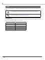
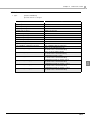
Peripheral Device
Device
*
TM-DT Series
TM-i Series
Keyboard device
✔
✔
Barcode scanner
✔
✔
Input device
✔
✔
Serial communication device
✔
✔
USB device that can provide a control level equivalent
to serial communication devices *
✔
-
Will require separate installation of a serial-USB conversion driver.
Serial-USB conversion drivers with certain specifications may not be usable.
With the TM-DT Series, a peripheral device can be used with a device control script file developed by the user to match the device.
Also, an API for device control script is available. For details, see Device Control Script(p.141).
18
Chapter 1
Overview
Contents in the Package
Manual
❏ ePOS-Device XML User’s Manual (This Document)
❏ TM-T88V-DT Technical Reference Guide
❏ TM-T70II-DT Technical Reference Guide
❏ TM-H6000IV-DT Technical Reference Guide
❏ TM-T88V-i (TM-i Firmware Ver.4.0 or later) Technical Reference Guide
1
❏ TM-T70-i (TM-i Firmware Ver.4.0 or later) Technical Reference Guide
❏ TM-T20II-i Technical Reference Guide
❏ TM-T82II-i Technical Reference Guide
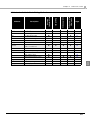
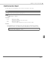
Sample Program
ePOS-Device_Sample_XML_Vx.x.x.zip
This contains the following.
❏ Sample program for Android
❏ Sample program for iOS
❏ Sample for device control script
File
Keyboard_Generic.js
Target Device
Keyboard
Scanner_Generic.js
Barcode scanner
SimpleSerial_Generic.js
Serial communication device
A sample program for an Android/ iOS environment is provided in the ePOS-Device XML.
For how to use the sample program, refer to Sample Program(p.149).
"Sample for device control script" is for use with TM-DT. It is not used with the TM-i Series.
Download
For customers in North America, go to the following web site:
http://www.epsonexpert.com/ and follow the on-screen instructions.
For customers in other countries, go to the following web site:
https://download.epson-biz.com/?service=pos
19
Restrictions
❏ The ruled line command is available only when the printer supports the "ruled line command".
❏ The drawer and the buzzer cannot be used together.
❏ The buzzer function cannot be used if the printer is not provided with the buzzer.
❏ When a 2D-code scanner is used, multibyte characters such as Japanese cannot be obtained properly.
❏ When 2D-code data contains an ASCII control code (0x00 to 0x1F), control codes cannot be obtained.
❏ Keycodes that can be obtained from the keyboard are restricted. For the key codes that can be
obtained, refer to List of KeyCode(p.185).
❏ Device control script files cannot be registered in a TM-i Series printer.
❏ Serial communication devices cannot be used with a TM-i Series printer with the specification of "without
Serial port".
20
Chapter 2
Building Environment
Building Environment
This chapter describes environment building for ePOS-Device Service I/F.
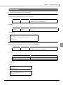
Updating the ePOS-Device
Once you have updated the ePOS-Device, you can use the new ePOS-Device functions.
TM-DT Series
Confirming the ePOS-Device version
You can confirm the version of the ePOS-Device on the EPSON TMNet WebConfig title bar.
2
Downloading the ePOS-Device update program
Download the following file from the Epson website and save it in your local environment.
• File name: ePOS-Device System Update Package
For more information about the update method, refer to the Readme file in the ePOS-Device update
package.
The ePOS-Device cannot be rolled back to an earlier version.
21
TM-i Series
The TM-i Series TM-i Firmware Ver.4.0 and later support ePOS-Device.
Confirming the TM-i Firmware version and the ePOS-Device version
There are the following two ways of checking the TM-i Firmware version.
❏ Checking [Firmware] and [ePOS-Device] in the status sheet
<General Information>
Firmware
X.XX
ePOS-Device
X.XX
Model
❏ Checking via EPSON TMNet WebConfig
TM-i Firmware: use [About] to check
ePOS-Device: use [General] to check
Updating the TM-i Firmware
Contact the distributor for how to update the firmware.
22
Chapter 2
Building Environment
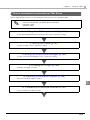
Workflow
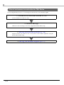
TM-DT Series
1. Network Settings
Configure the system and TM-DT network settings. For the TM-DT network settings, use
either of the following procedures:
Configuring the Windows network settings with TM-DT
Installing TMNet WinConfig in an external device (Windows computer) to be used
for configuration
2
2. Connection of Device to TM-DT
Connect a device to TM-DT. For the devices that can be connected, refer to Operating
Environment (p.16).
(Though TM-DT has only one port for serial communication device, USB connection is
available with a serial-USB conversion cable and driver.)
3. Registration of Device Control Script (TM-DT Series) (p.25)
For devices for which the device control script prepared in advance cannot be used,
register the device control script developed by the user from a Web browser.
4. Registration of Device (p.27)
Register the device to be connected into TM-DT. Make registration using a Web browser.
Necessary step
Optional step
23
TM-i Series
1.Connection of Device to TM-i
Connect a device to TM-i. For the devices that can be connected, refer to Operating
Environment (p.16).
2. Network Settings
Configure the system and TM-i network settings.
These settings can be made via the following. For details, refer to the Technical Reference Guide
of each TM-i.
EPSON TMNet WebConfig
EpsonNet Config
Easy Kitting
3."Registration of Device" on page 27
Register the device to be connected into TM-i. Make registration using a Web browser.
24
Chapter 2
Building Environment
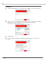
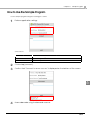
Registration of Device Control Script (TM-DT Series)
This section describes how to register the device control script prepared by the user in advance.
2
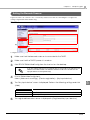
Use the following procedure for registration:
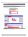
1
2
3
Prepare the customized device control script.
Make sure that the TM-DT's power is turned on.
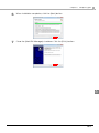
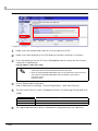
Start EPSON TMNet WebConfig from the shortcut on the desktop.
• If you are making settings from an external device, set the TM-DT IP address in the
address for the Web browser. The default IP address for TM-DT is 192.168.192.168.
http://[IP address of TM-DT]/webconfig/
• Check the IP address of TM-DT with the status sheet. For checking method of the
status sheet, refer to Technical Reference Guide of each TM-DT.
• If the Windows Security screen appears while using EPSON TMNet WebConfig,
enter your user name and password. The default values are as follows:
User name : epson
Password : epson
25
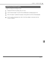
4
5
6
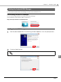
26
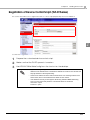
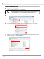
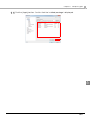
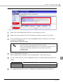
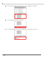
TMNet WebConfig starts.
Click [Web Service Settings] - [Add/delete].
The "Control Script" screen appears.
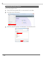
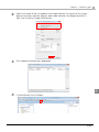
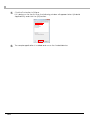
Click [Browse] under [Control Script to be registered] and select the device control
script to be registered.
Click [Add].
The device control script is registered and listed in [Registered control script] at the
bottom of the screen.
Chapter 2
Building Environment
Registration of Device
Register the device to be controlled by ePOS-Device XML into TM-Intelligent. Configure the settings using
EPSON TMNet WebConfig.
TM-DT Series
2
Configure the settings in the following procedure:
1
2
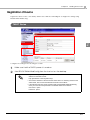
Make sure that the TM-DT's power is turned on.
Start EPSON TMNet WebConfig from the shortcut on the desktop.
• If you are making settings from an external device, set the TM-DT IP address in the
address for the Web browser.
http://[IP address of TM-DT]/webconfig/
• Check the IP address of TM-DT with the status sheet. For checking method of the
status sheet, refer to Technical Reference Guide of each TM-DT.
• If the Windows Security screen appears while using EPSON TMNet WebConfig,
enter your user name and password. The default values are as follows:
User name : epson
Password : epson
27
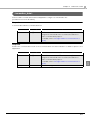
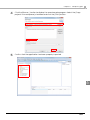
3
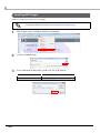
EPSON TMNet WebConfig starts.
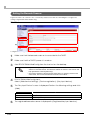
From [Web Service Settings] - [Device registration], click an applicable item
according to the device type to be registered.
Item
4
Description
Printer
Used to set a TM printer to be controlled by TM-DT.
Customer Display
Used to set a customer display to be controlled by TM-DT.
Key input device
Used to set a key input device to be controlled by TM-DT.
Serial communication device
Used to set a serial communication device to be controlled by
TM-DT.
Other
Used to set other device to be controlled by TM-DT.
The setting screen for each device appears.
Register the connected device into TM-DT.
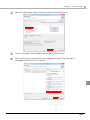
❏ Printer
Confirm that the local printer is registered using the following procedure:
1. Confirm that TM-DT is registered for the device ID "local_printer" in [Registered printers].
2. Click [Test printing]. Ensure that "TEST_PRINT" is printed.
Register the connected network printer using the following procedure:
1. Set the following items and click [Add].
Item
Description
Device ID
Enter the ID (any character string) of the printer to be controlled.
Type
Select "Network printer".
Model no.
Select the model of the printer to be controlled.
IP Address
Specify the IP address of the printer for each device ID.
Retry interval
Specify the retry interval after timeout.
2. After confirming that the printer is added to [Registered printers], click [Test printing].
Ensure that "TEST_PRINT" is printed.
If the registered printer is a hybrid printer, click [Operating test].
The "Operating test" window screen appears. Check the receipt, slip, endorse, and MICR
operations.
❏ Customer Display
The device ID of the customer display is fixed to "local_display".
Register the connected customer display in the following procedure:
1. Select [Use].
2. Set the following items and click [Apply].
Item
Description
Communications
settings
Set the communication speed, data bit and parity.
Brightness settings
Set the brightness of the customer display.
3 Click [Display test]. Confirm that the characters are displayed on the customer display.
28
Chapter 2
Building Environment
❏ Key Input Device
Register the connected key input device in the following procedure:
1. Set the following items and click [Add].
Item
Description
Device ID
Enter the device ID (any character string).
Device name
Select the device name of the key input device.
Control Script
Select the device control script to be used for the key input
device.
2. After confirming that the device is added to [Registered key input devices], click
[Operating test].
3. The screen appears. Operate the key input device and confirm that the operation result is
displayed properly.
❏ Serial Communication Devices
Register the connected serial communication device in the following procedure:
1. Set the following items for the connected serial communication device and click [Add].
Item
2
Description
Device ID
Enter the device ID (any character string).
Device name
Select the device name of the serial communication device.
The name can be selected from the product names and ports.
Control script
Select the device control scr ipt to be used for the ser ial
communication device.
Communication
speed(bps)
Set the communication speed of the device.
Data bit
Set the data bit.
Parity
Set the parity.
Stop bit
Set the stop bit.
Flow control
Set the flow control.
2. Confirm that the device is added to [Registered serial communication devices].
❏ Other
Register the connected device in the following procedure:
1. Set the following items for the connected device and click [Add].
Item
Description
Device ID
Enter the device ID (any character string).
Control script
Select the device control script to be used for the connected
device.
2. Confirm that the device is added to [Other registered devices].
29
TM-i Series
Configure the settings in the following procedure:
1
2
Make sure that the power to the TM-i and the network computer is turned on.
Enter the following into the URL entry field (address bar or similar) on the network
computer's web browser:
http://[IP address of TM-i]/webconfig/
• Check the IP address of TM-i with the status sheet. For checking method of the
status sheet, refer to Technical Reference Guide of each TM-i.
When accessing EPSON TMNet WebConfig, you are promoted to enter user name
and password of EPSON TMNet WebConfig. The default is shown below.
User name: epson
Password: epson
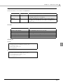
3
EPSON TMNet WebConfig starts.
From [Web serv settings] - [Device registration], click an applicable item according
to the device type to be registered.
Item
30
Description
Printer
Used to set a TM printer to be controlled by TM-i.
Customer Display
Used to set a customer display to be controlled by TM-i.
Key Input Device
Used to set a key input device to be controlled by TM-i.
Serial Communications Device
Used to set a serial communication device to be controlled by
TM-i.
Chapter 2
4
Building Environment
The setting screen for each device appears.
Register the connected device into TM-i.
❏ Printer
Confirm that the local printer is registered using the following procedure:
1. Confirm that "TM-i" is registered for the device ID "local_printer" in [Registered printers].
2. Click [Test printing]. Check that printing can be done in the registered printer.
Register the connected network printer using the following procedure:
1. Set the following items and click [Add].
Item
Description
Device ID
Enter the ID (any character string) of the printer to be controlled.
Model
Select the model of the printer to be controlled.
IP Address
Specify the IP address of the printer for each device ID.
Retry interval(ms)
Specify the retry interval after timeout.
2. After confirming that the printer is added to [Registered printers], click [Test printing].
Check that printing can be done in the registered printer.
2
❏ Customer Display
The device ID of the customer display is fixed to "local_display".
Register the connected customer display in the following procedure:
1. Select [Use].
2. Set the following items and click [Apply].
Item
Description
Communications
settings
Set the communication speed, data bit and parity.
Brightness settings
Set the brightness of the customer display.
3 Click [Test display]. Confirm that the characters are displayed on the customer display.
❏ Key Input Device
Register the connected key input device in the following procedure:
1. Set the following items and click [Add].
Item
Description
Device ID
Enter the device ID (any character string).
Device name
Select the device name of the key input device.
Control Script
Select the device control script to be used for the key input
device.
2. After confirming that the device is added to [Registered key input device], click [ Operating
test].
3. The screen appears. Operate the key input device and confirm that the operation result is
displayed properly.
31
❏ Serial Communication Device
The device ID of the customer display is fixed to "local_display".
Register the connected serial communication device in the following procedure:
1. Select [Use].
2. Set the following items for the connected serial communication device and click [Add].
Item
Description
Communication speed(bps)
Set the communication speed of the device.
Data bit
Set the data bit.
Parity
Set the parity.
Stop bit
Set the stop bit.
Flow control
Set the flow control.
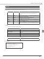
3. Click [Communication test].
4. The screen appears. Send a command to check for correct operation.
32
Chapter 3
Programming Guide
Programming Guide
This chapter describes how to write programs in the application development using ePOS-Device.
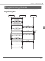
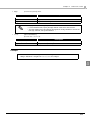
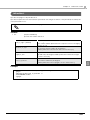
Programming Flow
The basic programming sequence of ePOS-Device XML is as follows:
Applications
ePOS-Device
Device
1 : Establishment of TCP/IP connection()
TCP connection to Socket I/F from
the native application
2 : connect message()
Establish a communication path to
ePOS-Device Service I/F
3 : open_device message(type_printer)
3.1 : Cmd()
4 : Device open
3
4.1 : Response()
6 : device_data message
6.1 : Cmd()
6.1.1 : Execute
Control device using device_data message
Response to device_data message
7 : Execution result
7.1 : device_data message()
7.1 : error message()
8: close_device message
Cut connection ePOS-Device Service I/F
and Socket I/F communication
8.1 : Cmd()
9: Device close
9.1 : Response()
10 : disconnect message()
Disconnection of TCP/IP connection
33
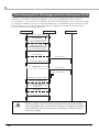
If Reconnecting to the TM-Intelligent when the Network was Cut Off
If network communication with the TM-Intelligent is cut off, the client application will reconnect. By
reconnecting, you can use the devices that were open without reopening them. Also, through the settings
for opening, the data to be sent to the client application that occurred while the network was cut off can
be received upon reconnection. The following sequence explains the message flow necessary upon
reconnection and the necessary parameters.
Applications
ePOS-Device
Device
1 : Establishment of TCP/IP connection()
TCP connection to Socket I/F from
the native application
2 : connect message(client_id=0001)
Establish a communication path to
ePOS-Device Service I/F
3 : open_device message(buffer=true)
Response(data_id=1)
4 : Data occurred()
4.1 : device_data message(Data, data_id=2)
Network is cut off
5 : Data occurred()
5.1 : Retains inside (data_id=3)
6 : Establishment of TCP/IP connection()
connect message(client_id=0002)
7: reconnect message
(new_client_id = 0002, old_client_id = 0001,
received_id = 2)
Response(OK)
8 : device_data message(Data, data_id=3)
To open an unopen device from the client, be sure to send a <disconnect> message when
closing the application. Also, in cases where you cannot send a <disconnect> message
when closing the application, store the previous <client_id> in the application's permanent
memory beforehand, and upon the next start-up, use the previous <client_id> to send a
<disconnect> message.
34
Chapter 3
Programming Guide
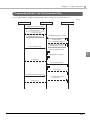
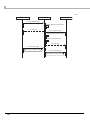
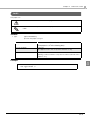
Programming flow for the Communication Box
The following indicates the basic programming sequence using the Communication Box.
[1/2]
Application A
ePOS-Device
Application B
1 : Establishment of TCP/IP connection()
TCP connection to Socket I/F from
the native application
2 : connect message()
Establishes communication path
with ePOS-Device Service I/F
1 : Establishment of TCP/IP connection()
TCP connection to Socket I/F from
the native application
2 : connect message()
3 : open_commbox message
Establishes communication path
with ePOS-Device Service I/F
3.1 : Creates the Communication Box
3
3.2 : Adds Application A to members
3.3 : Response()
3 : open_commbox message
3.2 : Adds Application B to members
3.3 : Response()
4 : commbox_data message(type:send)
4.2 : commbox_data message
(type:onreceive)
4.3 : Response()
35
[2/2]
Application A
ePOS-Device
Application B
5 : close_commbox message
5.1 : Deletes Application A from members
5.3 : Response()
5 : close_commbox message
5.1 : Deletes Application B from members
5.2 : Ends the Communication Box
5.3 : Response()
6 : disconnect message()
Disconnection of TCP/IP connection
6 : disconnect message()
Disconnection of TCP/IP connection
36
Chapter 3
Programming Guide
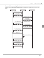
If automatically reconnecting the network
If network communication with the TM-Intelligent was reconnected, the Communication Box sequence is as
follows.
Application A
Application B
ePOS-Device
1 : Establishment of TCP/IP connection()
TCP connection to Socket I/F from
the native application
2 : connect message(client_id=0001)
Establishes communication path
with ePOS-Device Service I/F
1 : Establishment of TCP/IP connection()
TCP connection to Socket I/F from
the native application
2 : connect message(client_id=0001)
3 : open_commbox message()
Establishes communication path
with ePOS-Device Service I/F
3.1 : Response(data_id=1)
3 : open_commbox message()
3
3.1 : Response(data_id=1)
4 : commbox_data message(type:send)
4.1 : commbox_data message
(type:onreceive, data_id=2)
Network is cut off
5 : commbox_data message(type:send)
5.1 : Retains inside (data_id=3)
6 : Establishment of TCP/IP connection()
6.1 : connect message(client_id=0002)
7 : reconnect message
(new_client_id = 0002, old_client_id = 0001,
received_id = 2)
7.1 : Response(OK)
5.2 : commbox_data message
(type:onreceive, data_id=3)
37
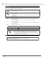
Service Interface Specifications
To enable control using ePOS-Device XML, use the following interface:
Transport layer
TCP
Port No.
8009
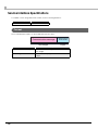
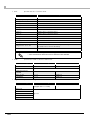
Format
The format and description of each data item are as follows:
Data name
38
Communication message
Terminating
character
Any length
1 byte
Description
Communication message
"UTF-8" character string in XML format
Any length
Terminating character
NULL character ("\0")
1 byte
Chapter 3
Programming Guide
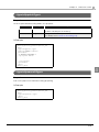
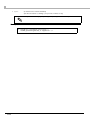
Communication Data Example
Examples of communication data between the application and ePOS-Device are as shown below, where
the NULL character is indicated as "\0".
Applications
ePOS-Device
Establishment of TCP/IP connection
Description
Establishment
of connection
<connect>
<data>
<client_id>sock3514555410
</client_id>
<protocol_version>2
</protocol_version>
</data>
</connect>"\0"
<admin_info></admin_info>"\0"
<admin_info>
<code>OK</code>
<data>
<admin_name>ep-admin</admin_name>
<location>Counter01</location>
</data>
</admin_info>"\0"
Acquisition of
the
administrator
information.
3
Device open
<open_device>
<device_id>keyboard01</device_id>
<data>
<type>type_keyboard</type>
<buffer>true</buffer>
</data>
</open_device>"\0"
<open_device>
<device_id>keyboard01</device_id>
<code>OK</code>
<data_id>1</data_id>
</open_device>"\0"
<device_data>
<device_id>keyboard01</device_id>
<data>
<type>setprefix</type>
<keycode>49</keycode>
<keycode>50</keycode>
<keycode>51</keycode>
</data>
</device_data>"\0"
Device control
39
Applications
ePOS-Device
Description
<device_data>
<device_id>keyboard01</device_id>
<data>
<type>onkeypress</type>
<keycode>49</keycode>
<ascii>a</ascii>
</data>
<data_id>2</data_id>
</device_data>”\0”
Device control
<device_data>
<device_id>keyboard01</device_id>
<data>
<type>onstring</type>
<input>11223344556677</input>
<prefix>a</prefix>
</data>
<data_id>3</data_id>
</device_data>”\0”
Key event (data_id=4) occurred
Detect a
disconnection
<connect><data>
<data>
<client_id>sock3514555411
</client_id>
<protocol_version>2
</protocol_version>
</data></data></connect>"\0"
Begin
reconnection
<data>
<old_client_id>sock3514555410
</old_client_id>
<new_client_id>sock3514555411
</new_client_id>
<received_id>3</received_id>
</data>
</reconnect>
<reconnect>
<code>OK</code>
</reconnect>"\0"
<device_data>
<device_id>keyboard01</device_id>
<data>
<type>onkeypress</type>
<keycode>50</keycode >
<ascii>b</ascii >
</data>
<data_id>4</data_id>
</device_data>"\0"
Device close
<close_device>
<device_id>keyboard01</device_id>
</close_device>"\0"
<close_device>
<device_id>keyboard01</device_id>
<code>OK</code>
<data_id>5</data_id>
</close_device>"\0"
40
Chapter 3
Applications
<disconnect>
<data>
<client_id>sock3514555411
</client_id>
</data>
</disconnect>
ePOS-Device
Programming Guide
Description
Disconnection
of connection
3
41
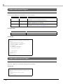
Communication Box Message Example
Application A
ePOS-Device
Application B
Opens the Communication Box
<open_commbox>
<sequence>1</sequence>
<data>
<box_id>
box1
</box_id>
<member_id>
member1
</member_id>
</data>
</open_commbox>"\0"
<open_commbox>
<sequence>1</sequence>
<data>
<box_id>box1</box_id>
<code>OK</code>
</data>
<data_id>1</data_id>
</open_commbox>"\0"
<open_commbox>
<sequence>1</sequence>
<data>
<box_id>
box1
</box_id>
<member_id>
member2
</member_id>
</data>
</open_commbox>"\0"
<open_commbox>
<sequence>1</sequence>
<data>
<box_id>box1</box_id>
<code>OK</code>
</data>
<data_id>1</data_id>
</open_commbox>"\0"
Forwards data to the Communication Box
<commbox_data>
<sequence>2</sequence>
<data>
<type>send</type>
<box_id>box1</box_id>
<message>
send_message
</message>
</data>
</commbox_data>"\0"
42
Chapter 3
Application A
ePOS-Device
Programming Guide
Application B
<commbox_data>
<sequence>2</sequence>
<data>
<type>onreceive</type>
<box_id>box1</box_id>
<sender_id>
member1
</sender_id>
<receiver_id>
</receiver_id>
<message>
send_message
</message>
</data>
<data_id>2</data_id>
</commbox_data>"\0"
<commbox_data>
<sequence>2</sequence>
<data>
<type>send</type>
<box_id>box1</box_id>
<code>OK</code>
<count>1</count>
</data>
<data_id>2</data_id>
</commbox_data>"\0"
3
Acquires the transfer history of the Communication Box
<commbox_data>
<sequence>2</sequence>
<data>
<type>
getcommhistory
</type>
<box_id>box1</box_id>
</data>
</commbox_data>"\0"
<commbox_data>
<sequence>2</sequence>
<data>
<type>
getcommhistory
</type>
<box_id>box1</box_id>
<code>OK</code>
<history_list>
<senderId>
member1
</senderId>
<receiverId>
</receiverId>
<message>
send_message
</message>
</history_list>
</data>
<data_id>3</data_id>
</commbox_data>"\0"
43
Application A
ePOS-Device
Application B
Closes the Communication Box
<close_commbox>
<sequence>3</sequence>
<data>
<box_id>box1</box_id>
</data>
</close_commbox>"\0"
<close_commbox>
<sequence>3</sequence>
<data>
<box_id>box1</box_id>
<code>OK</code>
</data>
<data_id>3</data_id>
</close_commbox>"\0"
<close_commbox>
<sequence>3</sequence>
<data>
<box_id>box1</box_id>
</data>
</close_commbox>"\0"
<close_commbox>
<sequence>3</sequence>
<data>
<box_id>box1</box_id>
<code>OK</code>
</data>
<data_id>4</data_id>
</close_commbox>"\0"
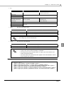
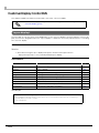
Array of <data> elements in <device_data> message
The following programming method is used to describe an array in the <data> tag:
❏ Specify the attribute array="true" at the beginning of the element to be used for the array.
❏ After that, specify a value with the same element name.
Example: To express "keycodes=[49, 50, 51, 52];"
<data>
<type>setprefix</type>
<keycodes array="true">49</keycodes>
<keycodes>50</keycodes>
<keycodes>51</keycodes>
<keycodes>52</keycodes>
</data>
44
Chapter 4
ePOS-Device XML
ePOS-Device XML
This chapter explains the ePOS-Device XML.
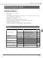
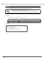
ePOS-Device XML List
ePOS-Device XML includes the following.
❏ Message(p. 45)
This is an XML for request messages from the application to the TM-Intelligent and response messages
from the TM-Intelligent to the application.
❏ Message Data for Communication Box (p. 46)
(in ePOS-Device Ver.2.5 and later)
This XML is used for data communication between applications.
This forms the sub-element for the <data> element in <commbox_data> messages.
❏ Message Data for Each Device (p. 46)
This XML stores the data for requests and responses for each controlled device.
This forms the sub-element for the <data> element in <device_data> messages.
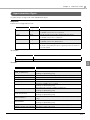
Message
Message
Description
Page
<connect>
Establishes a communication path with
ePOS-Device Service I/F
49
<reconnect>
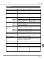
Re-establish communication route with
the ePOS-Device Service I/F
50
<disconnect>
Cut off communication route with
ePOS-Device Service I/F
51
Administrator
information
<admin_info>
Acquires administrator and installation
location information
52
Communication Box
<open_commbox>
Opens the Communication Box
54
(in ePOS-Device Ver.2.5 and
later)
<close_commbox>
Closes the Communication Box
56
<commbox_data>
Communication between applications
57
<open_device>
Opens communication with a device
58
<close_device>
Closes communication with a device
60
Communication path
Device open / close
Send device control data
Error notification
<device_data>
Requests device control
<device_data>
Responds to device control
<error>
Notifies you of error contents when an
error occurs
62
63
45
4
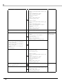
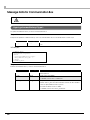
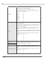
Message Data for Communication Box
Designates the data for data communication between applications with the sub-element for the <data>
element for the <commbox_data> message.
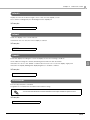
Before designating data, this designates the type of message data with the <type> element, then
designates the sub-element data. The <type> elements that can be used are listed in the chart below.
(in ePOS-Device Ver.2.5 and later)
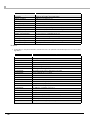
Value for <type>
element
Description
Page
getcommhistory
Acquires the transfer history of the Communication Box.
<Request>/<Response>
64
send
Sends data to the Communication Box. <Request>
66
onreceive
Notifies data from the Communication Box. <Response>
67
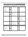
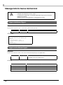
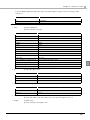
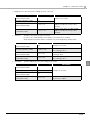
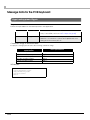
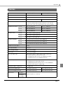
Message Data for Each Device
Designates the data to control the device with the sub-element of the <data> element for the
<device_data> message.
The component elements for message data vary based on the device type.
Before designating the data, designates the message data type with the <type> element, and then
designates the sub-element data. The device types and the <type> elements that can be used with each
TM intelligent printer are as in the table below.
* Serial devices cannot be used with a TM-i Series printer with the specification of "without a Serial port".
Device type
Value for <type>
element
TM-DT
Series
TM-i
Series
Page
Device Hub Terminal
shutdown
<Request>
Shuts down the TM-DT
✔
-
68
(in ePOS-Device
Ver.2.5 and later)
onshutdown
<Response>
Shutdown result of the TM-DT
✔
-
68
Barcode Scanner
ondata
<Response>
Scan data from a barcode
scanner
✔
✔
69
print
<Request>
Print data and setting data to
printers
✔
✔
70
onxmlresult
<Response>
Data from printers
✔
✔
70
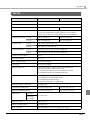
Printer
46
Description
Chapter 4
ePOS-Device XML
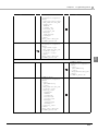
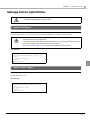
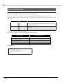
* Serial devices cannot be used with a TM-i Series printer with the specification of "without a Serial port".
Device type
Value for <type>
element
TM-DT
Series
TM-i
Series
Page
lock
<Request>
Locks the device port
✔
-
71
unlock
<Request>
Unlocks the device port
✔
-
71
print
<Request>
Print data and setting data to
receipt printers
✔
-
72
onxmlresult
<Response>
Data from receipt printers
✔
-
72
slipprint
<Request>
Print data and setting data to
slip printers
✔
-
73
slipcancel
<Request>
Cancels the paper insert wait
status during slip printing
✔
-
73
endorseprint
<Request>
Print data and setting data to
slip printers
✔
-
74
endorsecancel
<Request>
Cancels the paper insert wait
status during endorse printing
✔
-
74
micrread
<Request>
MICR reading
✔
-
75
micrcancel
<Request>
Cancels the paper insert wait
status during MICR reading
✔
-
76
micreject
<Request>
Ejects the check paper
✔
-
76
micrcleaning
<Request>
Cleans the MICR mechanism
✔
-
76
onreceive
<Response>
Hybrid printer processing
result
✔
-
77
display
<Request>
Display data and setting data
to the customer display
✔
✔
122
onxmlresult
<Response>
Data from the customer display
✔
✔
123
Hybrid Printer
(in ePOS-Device
Ver.2.5 and later)
Description
Customer Display
47
4
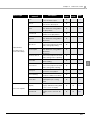
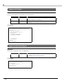
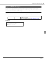
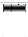
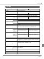
* Serial devices cannot be used with a TM-i Series printer with the specification of "without a Serial port".
Device type
POS Keyboard
Value for <type>
element
TM-DT
Series
TM-i
Series
Page
onkeypress
<Response>
Input character strings from
the POS keyboard
✔
✔
134
setprefix
<Request>
Designates the key code to
determine the start of character strings to detect input
from the POS keyboard
✔
✔
135
onstring
<Response>
Input character strings from
the POS keyboard
✔
✔
136
setMSRPrefix
<Request>
Designates the keycode for
determining the card information reception with the
keyboard with an MSR
✔
✔
137
ondata
<Response>
Card information from a
keyboard with an MSR
✔
✔
138
sendcommand
<Request>
Sends commands to the serial
device
✔
✔
139
oncommandreply
<Response>
Data from the serial device
✔
✔
140
Serial Device
48
Description
Chapter 4
ePOS-Device XML
Messages
<connect>
Response
Returns to the application that the connection was established.
Sub-element
data
Data type
string
Description
Connection information
For details, refer to the data below.
(Returned only when the connection is successful.)
Send the following message with the application, triggered by receiving this message.
❏ data
Sub-element
Data type
Description
client_id
string
ID of the connected client
protocol_version
string
Version of the connected TM-Intelligent
❏ Example
4
<connect>
<data>
<client_id>1234567890</client_id>
<protocol_version>2.0</protocol_version>
</data>
</connect>
49
<reconnect>
Notifies the confirmation of reconnection for network communication with the TM-Intelligent.
Request
Requests confirmation of reconnection to the TM-Intelligent.
Sub-element
Data type
Description
old_client_id
string
Specifies the client_id received by <connect> from the
previous session.
new_client_id
string
Specifies the client_id received by <connect> from the current session.
received_id
int
Specifies what last received communication with the
data_id received from all communication data
❏ Example
<reconnect>
<data>
<new_client_id>1234567890</new_client_id>
<old_client_id>0987654321</old_client_id>
<received_id>112</received_id>
</data>
</reconnect>
Response
Returns the confirmation result for reconnection to the application.
Sub-element
code
Data type
string
Description
Confirmation result for reconnection.
For details, refer to the code below.
❏ code
Element value
“OK”
Successfully reconnected
"CLIENT_NOT_FOUND"
A connection that corresponds to the specified client_id
does not exist
"PARAM_ERROR"
Parameter error occurred
“SYSTEM_ERROR”
System error occurred
❏ Example
Normal
<reconnect>
<code>OK</code>
</reconnect>
Error
<reconnect>
<code>"PARAM_ERROR"</code>
</reconnect>
50
Description
Chapter 4
ePOS-Device XML
<disconnect>
Closes the TCP connection with the TM-Intelligent.
Request
Requests that the TM-Intelligent close the connection.
Sub-element
data
Data type
string
Description
Client information to close the connection.
For details, refer to the data below.
❏ data
Sub-element
client_id
Data type
string
Description
Specifies the client_id to close the connection from the TMIntelligent.
❏ Example
<disconnect>
<data>
<client_id>1234567890</client_id>
</data>
</disconnect>
Response
4
Returns the TCP connection disconnection result to the application.
Sub-element
code
Data type
string
Description
Confirmation result for reconfirmation.
For details, refer to the code below.
❏ code
Element value
Description
“OK”
Close the TCP connection
"PARAM_ERROR"
Parameter error occurred
“SYSTEM_ERROR”
System error occurred
❏ Example
Normal
<disconnect>
<code>OK</code>
</disconnect>
Error
<disconnect>
<code>"PARAM_ERROR"</code>
</disconnect>
51
<admin_info>
Returns the administrator information set in the TM-Intelligent.
The information is set with EPSON TMNet WebConfig.
Request
Requests the administrator information from the TM-Intelligent.
❏ Example
<admin_info></admin_info>
Response
Returns the administrator information to the application.
Sub-element
Data type
Description
code
string
Result of acquiring the administrator information
For details, refer to the code below.
data
string
Administrator information
Only returned if successfully acquired.
For details, refer to the data below.
❏ code
Element value
Description
“OK”
Successfully acquired
"PARAM_ERROR"
Parameter error occurred
“SYSTEM_ERROR”
System error occurred
❏ data
Sub-element
Data type
Description
admin_name
string
Administrator information
location
string
Installation location information
Character strings in received data
Escape processing is performed for the following character strings.
Character string before
replacement
52
After replacement
& (Ampersand)
&
> (Greater-than symbol)
>
< (Lesser-than symbol)
<
"(Double quotation mark)
"
' (Single quotation mark)
'
Chapter 4
ePOS-Device XML
❏ Example
Normal
<admin_info>
<code>OK</code>
<data>
<admin_name>Administrator A</admin_name>
<location>Counter1&Counter2</location>
</data>
</admin_info>
Error
<admin_info>
<code>"PARAM_ERROR"</code>
</admin_info>
4
53
<open_commbox>
Opens the Communication Box and enables communication between applications.
(in ePOS-Device Ver.2.5 and later)
Request
Requests opening of the Communication Box.
Sub-element
Data type
Description
sequence
string
Sequence number
data
string
Information of the Communication Box to open.
For details, refer to the data below.
❏ data
Sub-element
Data type
box_id
string
Identifier of the Communication Box to open.
member_id
string
Member ID for identifying the client (application) in the
Communication Box.
❏ Example
<open_commbox>
<sequence>1</sequence>
<data>
<box_id>box1</box_id>
<member_id>member1</member_id>
</data>
</open_commbox>
54
Description
Chapter 4
ePOS-Device XML
Response
Returns the Communication Box open result to the application.
Sub-element
Data type
Description
sequence
string
The sequence number designated with the request.
data
string
Information of the Communication Box open result.
data_id
string
ID for identifying the sent data.
For details, refer to the data below.
❏ data
Sub-element
Data type
Description
box_id
string
Identifier of the Communication Box that is opened.
code
string
The processing result.
For details, refer to the code below.
code
Element value
Description
“OK”
Successfully opened the Communication Box.
“ALREADY_OPENED”
The Communication Box is already opened.
“MEMBERID_ALREADY_USED”
The specified member ID is already in use.
“BOX_COUNT_OVER”
The maximum number of Communication Boxes that can
be made is exceeded.
“BOX_CLIENT_OVER”
The maximum number that can belong to a Communication Box is exceeded.
“PARAMETER_ERROR”
Parameter error occurred
“SYSTEM_ERROR”
System error occurred
4
55
<close_commbox>
Closes the Communication Box. (in ePOS-Device Ver.2.5 and later)
Request
Requests closing of the Communication Box.
Sub-element
Data type
Description
sequence
string
Sequence number
data
string
Information of the Communication Box to close.
For details, refer to the data below.
❏ data
Sub-element
box_id
Data type
string
Description
Identifier of the Communication Box to close.
❏ Example
<close_commbox>
<sequence>2</sequence>
<data>
<box_id>box1</box_id>
</data>
</close_commbox>
Response
Returns the Communication Box close result to the application.
Sub-element
Data type
Description
sequence
string
The sequence number designated with the request.
data
string
Information of the Communication Box close result.
For details, refer to the data below.
data_id
string
ID for identifying the sent data.
❏ data
Sub-element
Data type
Description
box_id
string
Identifier of the Communication Box that is closed.
code
string
The processing result.
For details, refer to the code below.
code
Element value
56
Description
“OK”
Successfully closed the Communication Box.
“NOT_OPENED”
A Communication Box is not open.
“SYSTEM_ERROR”
System error occurred
Chapter 4
ePOS-Device XML
<commbox_data>
Performs data communication between applications using the Communication Box.
(in ePOS-Device Ver.2.5 and later)
Request
Communicates with the Communication Box.
Sub-element
Data type
Description
sequence
string
Sequence number
data
string
The data used for communication between applications
using the Communication Box. Contents are defined for
each communication purpose.
For details, refer to Message Data for Communication Box
(p.46).
Response
Returns the communication result of the Communication Box and notification of data reception to the
application.
Sub-element
Data type
Description
sequence
string
The sequence number designated with the request.
data
string
The data used for communication between applications
using the Communication Box. Contents are defined for
each communication purpose.
For details, refer to Message Data for Communication Box
(p.46).
data_id
int
4
ID for identifying the sent data.
57
<open_device>
Makes the device linked to the device ID usable. Provides exclusive use for the designated device to the
requesting application (except for printers).
Request
Designates the device to open.
Sub-element
device_id
Data type
string
Description
The device ID designated with EPSON TMNet WebConfig.
The customer display is "local_display".
data
string
For details, refer to the data below.
❏ data
Sub-element
type
Data type
string
Description
Specifies the device category name.
“type_dt”:
Device hub terminal (TM-DT)
(in ePOS-Device Ver.2.5 and later)
"type_scanner":
Barcode scanner
"type_keyboard":
POS keyboard
"type_printer":
Printer
“type_hybrid_printer”: Hybrid Printer
(in ePOS-Device Ver.2.5 and later)
buffer
string
"type_display":
Customer display
"type_simple_serial":
Serial communication device
Specifies the buffer function for when a connection is
disconnected.
"true"
:Enable
"false"
:Disable
With TM-i, the following devices are not supported:
“type_dt”
“type_hybrid_printer”
A TM-i Series printer with the specification of "without a Serial port" does not support
“type_simple_serial”.
❏ Example
<open_device>
<device_id>scanner_001</device_id>
<data>
<type>type_scanner</type>
</data>
</open_device>
58
Chapter 4
ePOS-Device XML
Response
Returns the device open result to the application.
Sub-element
Data type
Description
device_id
string
The device ID designated with the request.
code
string
The processing result.
data_id
int
If "true" is designated for <buffer> of the <open_device>
message, the sent data ID is set. If "false" is designated, a
space is set.
For details, refer to the code below.
❏ code
Element value
Description
“OK”
Processed successfully
“DEVICE_NOT_FOUND”
The designated device does not exist
“DEVICE_IN_USE”
The designated device is in use
“DEVICE_OPEN_ERROR”
Failed to open the designated device
“DRIVER_ERROR”
An error occurred in the device control script
“SYSTEM_ERROR”
System error occurred
“DEVICE_TYPE_INVALID”
The designated device type is invalid
"PARAM_ERROR"
Parameter error occurred
❏ Example
4
Normal
<open_device>
<device_id>scanner_001</device_id>
<code>OK</code>
<data_id>2</data_id>
</open_device>
Error
<open_device>
<code>DEVICE_NOT_FOUND</code>
<device_id>scanner_001</device_id>
<data_id>2</data_id>
</open_device>
59
<close_device>
Closes the opened device.
Request
Designates the device to close.
Sub-element
device_id
Data type
string
Description
The device ID designated with EPSON TMNet WebConfig.
The customer display is "local_display".
❏ Example
<close_device>
<device_id>local_display</device_id>
</close_device>
60
Chapter 4
ePOS-Device XML
Response
Returns the device close result to the application.
Sub-element
Data type
Description
device_id
string
The device ID designated with the request.
code
string
The processing result.
data_id
int
If "true" is designated for <buffer> of the <open_device>
message, the sent data ID is set. If "false" is designated, a
space is set.
For details, refer to the code below.
❏ code
Element value
Description
“OK”
Processed successfully
“DEVICE_NOT_FOUND”
The designated device does not exist
“DEVICE_NOT_OPEN”
The designated device ID is not open
“DEVICE_CLOSE_ERROR”
Failed to close the designated device
“SYSTEM_ERROR”
System error occurred
"PARAM_ERROR"
Parameter error occurred
❏ Example
Normal
4
<close_device>
<device_id>local_display</device_id>
<code>OK</code>
<data_id>2</data_id>
</close_device>
Error
<close_device>
<device_id>scanner_001</device_id>
<code>DEVICE_NOT_FOUND</code>
<data_id>2</data_id>
</close_device>
61
<device_data>
Request
Sends data to a device. Includes device control commands and print / display data.
Sub-element
Data type
Description
sequence
string
An arbitrary value to specify request messages during sending errors. If you designate a request message, it will be set in
the sequence of the error message during an error.
device_id
string
The opened device ID.
data
string
Data for device control. Contents are defined for each
device type. For details, refer to Message Data for Each
Device (p.46).
❏ Example
<device_data>
<sequence>123</sequence>
<device_id>poskeyboard001</device_id>
<data>
<type>setprefix</type>
<keycodes array="true">49</keycodes>
<keycodes>50</keycodes>
<keycodes>51</keycodes>
<keycodes>52</keycodes>
</data>
</device_data>
Response
Returns the data from the device. Includes the result of device control, events which occurred at the
device, and input data from the device.
Sub-element
Data type
Description
sequence
string
Fixed as 0
device_id
string
Device ID where the data occurred
data
string
Data that occurred. Contents are defined for each device
type. For details, refer to Message Data for Each Device
(p.46).
data_id
int
If "true" is designated for <buffer> of the <open_device> message, the sent data ID is set. If "false" is designated, a space is
set.
❏ Example
<device_data>
<sequence>0</sequence>
<device_id>poskeyboard001</device_id>
<data>
<type>onstring</type>
<input>&2398749238429</input>
<prefix>49</prefix>
</data>
<data_id>2</data_id>
</device_data>
62
Chapter 4
ePOS-Device XML
<error>
Response
Returns the device control command and other common errors.
Sub-element
sequence
Data type
string
Description
ID to specify the message that caused the error.
It is the same value as the sequence designated by the
request.
device_id
string
Device ID where the error occurred. Designated if an error is in
the device control message.
code
string
Displays the error that occurred using a code.
For details, refer to the following.
data
string
The details of errors based on the driver are designated when
a “DRIVER_ERROR” occurs.
data_id
int
If "true" is designated for <buffer> of the <open_device> message, the sent data ID is set. If "false" is designated, a space is
set.
❏ code
<When there is an error in <device_data>
Element value
Description
“DEVICE_NOT_FOUND”
The designated device ID does not exist
“DEVICE_NOT_OPEN”
The designated device is not open
“SEND_ERROR”
An error occurred sending the data to the physical
device
“DRIVER_ERROR”
Detected an error in the device
"PARAM_ERROR"
Parameter error occurred
“FUNCTION_NOT_FOUND”
The designated function does not exist in the driver
4
Any other error
Element value
“SYSTEM_ERROR”
Description
System error occurred
❏ Example
<error>
<sequence>123</sequence>
<device_id>scanner002</device_id>
<code>DEVICE_NOT_OPEN</code>
<data></data>
<data_id>2</data_id>
</error>
63
Message Data for Communication Box
Available with ePOS-Device Ver.2.5 or later.
<type>getcommhistory</type>
Acquires the transfer history of the Communication Box.
Request
Requests acquisition of transfer history of the Communication Box to the ePOS-Device Service I/F.
Sub-element
box_id
Data type
string
Description
Identifier of the Communication Box to acquire transfer history
from
❏ Example
<commbox_data>
<sequence>4</sequence>
<data>
<type>getcommhistory</type>
<box_id>box1</box_id>
</data>
</commbox_data>
Response
Returns the transfer history of the Communication Box.
Sub-element
Data type
Description
box_id
string
Identifier of the Communication Box whose transfer history
was acquired
code
string
Result of the sent data.
For details, refer to the code below.
history_list
string
Acquired transfer history.
Notifies <history_list> the same number of times as the number
of the acquired transfer history items.
Stored in the latest order of data.
For details, refer to the history_list below.
64
Chapter 4
ePOS-Device XML
❏ code
Element value
Description
“OK”
Successfully acquired transfer history of the Communication Box.
“NOT_OPENED”
A Communication Box is not open.
“SYSTEM_ERROR”
System error occurred
❏ history_list
Element value
senderId
Description
Sender's member ID
receiverId
Receiver's member ID
message
Received message
❏ Example
<commbox_data>
<sequence>4</sequence>
<data>
<type>getcommhistory</type>
<box_id>box1</box_id>
<code>OK</code>
<history_list>
<senderId>member1</senderId>
<receiverId></receiverId>
<message>send_message3</message>
</history_list>
<history_list>
<senderId>member1</senderId>
<receiverId></receiverId>
<message>send_message2</message>
</history_list>
<history_list>
<senderId>member1</senderId>
<receiverId></receiverId>
<message>send_message</message>
</history_list>
</data>
<data_id>10</data_id>
</commbox_data>
4
65
<type>send</type>
Forwards data to the Communication Box.
Request
Forwards messages to the Communication Box.
Sub-element
Data type
Description
box_id
string
Identifier of the Communication Box to forward the message to.
message
string
Message to forward.
member_id
string
Member ID to forward.
To forward message to all the clients (applications) belonging
to the Communication Box, specify " "(space).
❏ Example
<commbox_data>
<sequence>3</sequence>
<data>
<type>send</type>
<box_id>box1</box_id>
<message>send_message</message>
</data>
</commbox_data>
Response
Returns the message transfer result.
Sub-element
Data type
Description
box_id
string
Identifier of the Communication Box that forwarded the message
code
string
Forward result of the message.
For details, refer to the code below.
count
string
The number of clients that attempted to forward a message.
❏ code
Element value
66
Description
“OK”
Successfully forwarded the message.
“NOT_OPENED”
A Communication Box is not open.
“MEMBER_NOT_FOUND”
The specified member ID cannot be found.
“SYSTEM_ERROR”
System error occurred
Chapter 4
ePOS-Device XML
<type>onreceive</type>
Acquires the data forwarded to the Communication Box.
Response
Returns the message transfer result.
Sub-element
Data type
Description
box_id
string
Identifier of the Communication Box that forwarded the message.
sender_id
string
Member ID that forwarded the message.
receiver_id
string
Member ID that acquires the forwarded message.
(When all the clients (applications) belonging to the Communication Box acquire the message, " "(space) is returned.)
message
string
Message forwarded to the Communication Box.
❏ Example
<commbox_data>
<sequence>3</sequence>
<data>
<type>onreceive</type>
<box_id>box1</box_id>
<sender_id>member1</sender_id>
<receiver_id></receiver_id>
<message>send_message</message>
</data>
<data_id>19</data_id>
</commbox_data>
4
67
Message Data for Device Hub Terminal
• Cannot be used with TM-i Series.
• Available with ePOS-Device Ver.2.5 or later.
• If sending this message data, use EPSON TMNet WebConfig to perform shutdown
settings for the TM-DT.
([Settings]-[System settings]-[Shutdown settings]-[ePOS-Device])
<type>shutdown</type>
Request
Shuts down the power source of the device hub terminal (TM-DT).
Sub-element
password
Data type
string
Description
Specifies the password for EPSON TMNet WebConfig.
❏ Example
<device_data>
<device_id>local_dt</device_id>
<data>
<type>shutdown</type>
<password>epson</password>
</data>
</device_data>
<type>onshutdown</type>
Response
Returns the shutdown results of the device hub terminal (TM-DT) to the application.
Sub-element
status
Data type
string
Description
Result of the sent data.
For details, refer to the status below.
❏ status
Element value
68
Description
“SUCCESS”
Shutdown successfully completed
“AUTHENTICATION_ERROR”
Password authentication error
“ACCESS_DENIED”
Shutdown from ePOS-Device XML is not set
“SYSTEM_ERROR”
System error occurred
Chapter 4
ePOS-Device XML
Message Data for the Barcode Scanner
<type>ondata</type>
Response
Returns the scan data from the barcode scanner to the application.
Sub-element
input
Data type
string
Description
Scan data string received.
Character strings in received data
Escape processing is performed for the following character strings.
Character string before
replacement
After replacement
& (Ampersand)
&
> (Greater-than symbol)
>
< (Lesser-than symbol)
<
"(Double quotation mark)
"
' (Single quotation mark)
'
❏ Example
<data>
<type>ondata</type>
<input>F12345678909123</input>
</data>
4
69
Message Data for Printers
For print data, refer to Printer Control XML (p.79).
<type>print</type>
Request
Sends the print data and setting data to printers.
Sub-element
timeout
Data type
int
Description
Sets the time out limit for requests in milliseconds.
1,000 to 60,000 (whole numbers)
printdata
string
Designates the data to print.
For details, refer to Printer Control XML (p.79).
❏ Example
<data>
<type>print</type>
<timeout>10000</timeout>
<printdata>
<!-- Printer Control XML -->
<epos-print xmlns=
.
.
</epos-print>
</printdata>
</data>
<type>onxmlresult</type>
Response
Returns the print result to the application.
Sub-element
resultdata
Data type
string
Description
Result of the sent data.
For details, refer to <response> (p.81).
❏ Example
<data>
<type>onxmlresult</type>
<resultdata>
<response success=
/>
</resultdata>
</data>
70
Chapter 4
ePOS-Device XML
Message Data for Hybrid Printers
• Cannot be used with TM-i Series.
• Available with ePOS-Device Ver.2.5 or later.
<type>lock</type>
Request
Locks the device port. Execute when performing MICR reading or you want to lock the device.
If you locked a port with this message data, be sure to send the <type>unlock</type> (p.71)
message before closing the application.
If you close the application without sending the unlock, the next port cannot be locked for about
five minutes until the ePOS-Device Service I/F unlocks the port.
The <type>onreceive</type> (p.77) message returns 'ERROR_DEVICE_BUSY'.
❏ Example
<device_data>
<device_id>local_printer</device_id>
<data>
<type>lock</type>
</data>
</device_data>
4
<type>unlock</type>
Request
Unlocks the device port.
❏ Example
<device_data>
<device_id>local_printer</device_id>
<data>
<type>unlock</type>
</data>
</device_data>
71
<type>print</type>
Request
Sends the print data and setting data to the receipt printer.
Sub-element
Data type
Description
timeout
int
Sets the time out limit for requests in milliseconds.
printdata
string
Designates the data to print.
1,000 to 60,000 (whole numbers)
For details, refer to Printer Control XML (p.79).
❏ Example
<device_data>
<device_id>local_printer</device_id>
<data>
<type>print</type>
<timeout>10000</timeout>
<printdata>
<!-- Printer Control XML -->
<epos-print xmlns=
.
.
</epos-print>
</printdata>
</data>
</device_data>
<type>onxmlresult</type>
Response
Returns the receipt print result to the application.
Sub-element
resultdata
Data type
string
Description
Result of the sent data.
For details, refer to <response> (p.81).
❏ Example
<data>
<type>onxmlresult</type>
<resultdata>
<response success=
/>
</resultdata>
</data>
72
Chapter 4
ePOS-Device XML
<type>slipprint</type>
Request
Sends the print data and setting data to the slip printer.
Sub-element
Data type
timeout
int
printdata
string
Description
Specifies the timeout time (ms) for the paper insert wait status.
60,000 to 900,000 (whole numbers)
Designates the data to print.
For details, refer to Printer Control XML (p.79).
❏ Example
<device_data>
<device_id>local_printer</device_id>
<data>
<type>slipprint</type>
<timeout>60000</timeout>
<printdata>
<!-- Printer Control XML -->
<epos-print xmlns=
.
.
</epos-print>
</printdata>
</data>
</device_data>
4
<type>slipcancel</type>
Request
Cancels the paper insert wait status during slip printing.
❏ Example
<device_data>
<device_id>local_printer</device_id>
<data>
<type>slipcancel</type>
</data>
</device_data>
73
<type>endorseprint</type>
Request
Sends the print data and setting data to the endorse printer.
Sub-element
Data type
Description
40cplmode
boolean
Sets the 40cpl mode.
timeout
int
Specifies the timeout time (ms) for the paper insert wait status.
For details, refer to the 40cplmode below.
60,000 to 900,000 (whole numbers)
printdata
string
Designates the data to print.
For details, refer to Printer Control XML (p.79).
❏ 40cplmode
Element value
Description
true
Enables the 40cpl mode.
false
Disables the 40cpl mode.
❏ Example
<device_data>
<device_id>local_printer</device_id>
<data>
<type>endorseprint</type>
<40cplmode>false</40cplmode>
<timeout>60000</timeout>
<printdata>
<!-- Printer Control XML -->
<epos-print xmlns=
.
.
</epos-print>
</printdata>
</data>
</device_data>
<type>endorsecancel</type>
Request
Cancels the paper insert wait status during endorse printing.
❏ Example
<device_data>
<device_id>local_printer</device_id>
<data>
<type>endorsecancel</type>
</data>
</device_data>
74
Chapter 4
ePOS-Device XML
<type>micrread</type>
Request
Executes MICR reading.
If you set the paper after executing this message, MICR reading is performed.
Sub-element
Data type
Description
ignoreerror
boolean
Specifies the operation to perform when unreadable characters are detected.
font
string
Specifies the MICR font to read.
For details, refer to the ignoreerror below.
For details, refer to the font below.
timeout
int
Specifies the timeout time (ms) for the paper insert wait status.
60,000 to 900,000 (whole numbers)
❏ ignoreerror
Element value
Description
true
Replaces unreadable characters with ‘?’ and continues processing.
false
Stops processing.
❏ font
Element value
Description
"FONT_E13B"
Reads the E13B font.
"FONT_CMC7"
Reads the CMC7 font.
4
❏ Example
<device_data>
<device_id>local_printer</device_id>
<data>
<type>micrread</type>
<ignoreerror>true</ignoreerror>
<font>MICR_E13B</font>
<timeout>60000</timeout>
</data>
</device_data>
75
<type>micrcancel</type>
Request
Cancels the paper insert wait status during MICR reading or MICR mechanism cleaning.
❏ Example
<device_data>
<device_id>local_printer</device_id>
<data>
<type>micrcancel</type>
</data>
</device_data>
<type>micreject</type>
Request
Ejects the check paper.
❏ Example
<device_data>
<device_id>local_printer</device_id>
<data>
<type>micreject</type>
</data>
</device_data>
<type>micrcleaning</type>
Request
Cleans the MICR mechanism.
After executing this message, set the cleaning sheet to clean the MICR mechanism.
Sub-element
timeout
Data type
int
Description
Specifies the timeout time (ms) for the paper insert wait status.
60,000 to 900,000 (whole numbers)
❏ Example
<device_data>
<device_id>local_printer</device_id>
<data>
<type>micrcleaning</type>
<timeout>123456</timeout>
</data>
</device_data>
76
Chapter 4
ePOS-Device XML
<type>onreceive</type>
Acquires the processing result of the HybridPrinter object.
Response
Returns the message transfer result.
Sub-element
Data type
Description
eventtype
string
Method name that returns an event
success
string
Processing result of the method that returns an event.
code
string
Execution result of the method that returns an event.
For details, refer to the success below.
For details, refer to the code below.
status
string
Hybrid printer status.
data
string
Receives MICR reading data when the method that returns
an event is "micrread". Receives " "(space) when the method
is not "micrread".
For details, refer to the status below.
❏ success
Element value
Description
“true” or ”1”
Succeeded.
“false” or ”0”
Failed.
4
❏ code
Element value
'SUCCESS'
'EPTR_AUTOMATICAL'
Description
Succeeded
An automatically recoverable error occurred
(During receipt printing only)
'EPTR_COVER_OPEN'
A cover open error occurred (During receipt printing only)
'EPTR_CUTTER'
An autocutter error occurred
'EPTR_MECHANICAL'
A mechanical error occurred
'EPTR_REC_EMPTY'
No paper in roll paper end sensor
'EPTR_UNRECOVERABLE'
An unrecoverable error occurred
(During receipt printing only)
'SchemaError'
'DeviceNotFound'
'PrintSystemError'
'EX_BADPORT'
The request document contains a syntax error
(During receipt printing only)
The printer with the specified device ID does not exist
(During receipt printing only)
An error occurred on the printing system (During receipt printing
only)
An error was detected on the communication port
(During receipt printing only)
'EX_TIMEOUT'
A print timeout occurred (During receipt printing only)
'ERROR_DEVICE_NOT_FOUND'
The device cannot be found
77
Element value
Description
'ERROR_DEVICE_BUSY'
Failed to open the port
'CANCEL'
Cancels the paper insert wait status
'ERROR_TIMEOUT'
Paper insert wait timeout
'ERROR_PARAMETER'
Parameter error
'ERROR_NOT_SUPPORTED'
The endorse printer is not installed
'EPTR_SCHEMAERROR'
There is an error in the syntax of the request document
'ERROR_COMMAND'
The cancelled processing is not in the paper insert wait status
'EMICR_ILLEGAL_LENGTH'
The inserted paper is not the correct length
'EMICR_NO_MICR'
Did not detect MICR data
'EMICR_RECOGNITION'
Detected unrecognizable MICR text
'EMICR_READ'
Error occurred during MICR reading
'EMICR_NOISE_DETECTED'
Detected noise error
'EMICR_COVER_OPEN'
Cover was opened during MICR reading
'EMICR_PAPER_JAM'
Paper jam error occurred
❏ status
Depending on the printer situation, an OR function is acquired in a decimal expression from the following values.
Element value
78
Description
“0x00000001”
No response from the TM printer
“0x00000002”
Printing is successfully completed
“0x00000004”
Status of the 3rd pin of the drawer kick-out connector = "H"
“0x00000008”
Offline
“0x00000020”
The cover is open
“0x00000040”
Paper is being fed by a paper feed switch operation
“0x00000100”
Waiting to be brought back online
“0x00000200”
The paper feed switch is being pressed (ON)
“0x00000400”
A mechanical error occurred
“0x00000800”
An autocutter error occurred
“0x00002000”
An unrecoverable error occurred
“0x00004000”
An automatically recoverable error occurred
“0x00010000”
Slip section is waiting for paper to be inserted
“0x00020000”
No paper in roll paper near end sensor
“0x00040000”
Slip section is waiting for paper to be removed
“0x00080000”
No paper in roll paper end sensor
“0x00200000”
No paper in the TOF detector
“0x00400000”
No paper in the BOF detector
“0x01000000”
A buzzer is on (only for applicable devices)
“0x01000000”
Slip not selected
“0x02000000”
Cannot print on a slip
“0x80000000”
The spooler has stopped (Not used)
Chapter 4
ePOS-Device XML
Printer Control XML
This chapter explains the XML document that controls printers.
For printer message data, refer to Message Data for Printers (p.70).
<epos-print>
This is the XML document sent from the application to printers. It requests that the printer execute the designated function. <epos-print> contains the element.
Attribute
❏ xmlns
We're announcing the epos-print namespace. Find the namespace below.
http://www.epson-pos.com/schemas/2011/03/epos-print
❏ force
This is the forced transmission mode. (in ePOS-Device Ver.2.2 and later)
If you enable forced transmission mode, print commands are forcibly sent to the printer.
Attribute value
Description
true or 1
Sets forced transmission mode.
false or 0
Sets normal transmission mode.
4
• Use forced transmission mode when the printer is offline.
It will result in an error if the printer is online.
• The following functions are enabled in forced transmission mode.
Drawer kick-out (<pulse> (p.114))
Stopping the buzzer (<sound> (p.115))
Recovery from errors that can be recovered from (<recovery> (p.121))
Reset (<reset> (p.121))
Sending commands in real time (<command> (p.117))
79
Sub-element
Receipt/ Label printing
Slip printing
Endorse printing
Endorse printing
40cpl mode
Standard mode
Page mode
Printer's print mode
<text>
Prints text
●
●
●
●
●
●
84
<feed>
Paper feed
●
●
●
●
●
●
90
<image>
Prints raster image
●
▲
▲
▲
●
●
92
<logo>
Prints NV logo
●
●
▲
▲
●
●
94
<barcode>
Prints barcode
●
●
▲
▲
●
●
95
<symbol>
Prints symbol
●
▲
▲
▲
●
●
99
<hline>
Prints horizontal line
●
▲
▲
▲
●
▲
104
<vline-begin>
Starts vertical line
●
▲
▲
▲
●
▲
105
<vline-end>
Ends vertical line
●
▲
▲
▲
●
▲
106
<page>
Page mode
●
●
▲
▲
●
▲
107
Subelement
Function
<area>
Sets a page mode print area
●
▲
▲
▲
▲
●
108
<direction>
Sets a page mode print direction
●
●
▲
▲
▲
●
109
<position>
Sets a page mode print position
●
●
▲
▲
▲
●
110
<line>
Draws a page mode line
●
▲
▲
▲
▲
●
111
<rectangle>
Draws a page mode rectangle
●
▲
▲
▲
▲
●
112
<cut>
Paper cut
●
▲
▲
▲
●
▲
113
<pulse>
Drawer kick-out
●
●
●
●
●
▲
114
<sound>
Sounds a buzzer
●
▲
▲
▲
●
▲
115
<command>
Inserts a command
●
●
●
●
●
●
117
<layout>
Setting of paper layout
(in ePOS-Device Ver.2.2 and later)
●
▲
▲
▲
●
▲
118
<recovery>
Recovers from an error
(in ePOS-Device Ver.2.2 and later)
●
●
●
●
●
▲
121
<reset>
Resets the printer
(in ePOS-Device Ver.2.2 and later)
●
●
●
●
●
▲
121
❏ Example
<!-- Example with a text tag added as a sub-element -->
<epos-print xmlns=”http://www.epson-pos.com/schemas/2011/03/epos-print”>
<text>Hello world!!</text>
</epos-print>
80
Page
Chapter 4
ePOS-Device XML
<response>
This is an XML document that is returned from the printer to the application.
Attribute
❏ success
Obtains the print result.
Attribute value
Description
“true” or ”1”
Printing succeeded.
“false” or ”0”
Printing failed.
❏ code
Obtains the error code.
Attribute value
Description
“EPTR_AUTOMATICAL”
An automatically recoverable error occurred
“EPTR_COVER_OPEN”
A cover open error occurred
“EPTR_CUTTER”
An autocutter error occurred
“EPTR_MECHANICAL”
A mechanical error occurred
“EPTR_REC_EMPTY”
No paper in roll paper end sensor
“EPTR_UNRECOVERABLE”
An unrecoverable error occurred
“SchemaError”
The request document contains a syntax error
“DeviceNotFound”
The printer with the specified device ID does not exist
“PrintSystemError”
An error occurred on the printing system
“EX_BADPORT”
An error was detected on the communication port
“EX_TIMEOUT”
A print timeout occurred
4
81
❏ status
Depending on the printer situation, an OR function is acquired in a decimal expression from the following values.
Attribute value
No response from the TM printer
“0x00000002”
Printing is successfully completed
“0x00000004”
82
Description
“0x00000001”
Status of the 3rd pin of the drawer kick-out connector = "H"
Battery offline status
“0x00000008”
Offline
“0x00000020”
The cover is open
“0x00000040”
Paper is being fed by a paper feed switch operation
“0x00000100”
Waiting to be brought back online
“0x00000200”
The paper feed switch is being pressed (ON)
“0x00000400”
A mechanical error occurred
“0x00000800”
An autocutter error occurred
“0x00002000”
An unrecoverable error occurred
“0x00004000”
An automatically recoverable error occurred
“0x00020000”
No paper in roll paper near end sensor
“0x00080000”
No paper in roll paper end sensor
“0x01000000”
A buzzer is on (only for applicable devices)
“0x80000000”
The spooler has stopped (Not used)
Chapter 4
ePOS-Device XML
❏ battery
Depending on the battery situation, an OR function is acquired in a decimal expression from the following values.
Status of power
Attribute value
Description
0x30XX
The AC adapter is connected
0x31XX
The AC adapter is not connected
Remaining battery
Attribute value
Description
0xXX36
Battery amount 6
0xXX35
Battery amount 5
0xXX34
Battery amount 4
0xXX33
Battery amount 3
0xXX32
Battery amount 2
0xXX31
Battery amount 1 (Near end)
0xXX30
Battery amount 0 (Real end)
0 is indicated when the model doesn't have a battery installed.
Example
4
<!-- Printer status -->
<!-- Successfully performed. -->
<response success=”true” code=”” status=””/>
<!-- When the printer ran out of paper during printing and failed to print. -->
<response xmlns="http://www.epson-pos.com/schemas/2011/03/epos-print"
success="false" code="EPTR_REC_EMPTY" status="252641308" />
83
<text>
Prints a character string. Also, configure the string-related settings such as style, print position, and line feed
space.
After printing text, to print content other than text content, execute line feed or paper feed.
In page mode, characters are laid out in the current print position with the reference point being
the character baseline dot (Printer specifications (p.187)).
Entity Reference
To write symbols required for printer control such as horizontal tab, line feed, and the following symbols, use
their corresponding entity references shown as follows:
Function (symbol)
84
Entity Reference
&
&
'
'
>
>
<
<
"
"
Horizontal tab(HT)
	 or 	
Line feed (LF)
or 

Chapter 4
ePOS-Device XML
Endorse printing
Endorse printing
40cpl mode
Page
●
▲
▲
86
●
●
▲
87
▲
▲
▲
87
●
●
▲
87
●
●
●
▲
87
Horizontal scale
●
●
●
▲
87
Vertical scale
●
●
●
▲
88
Inversion of black and white
parts of characters
●
▲
▲
▲
88
ul
underline
●
●
●
▲
88
em
Emphasized printing
●
●
●
▲
88
Receipt/
Label printing
Slip printing
Attributes Available for Each Printing Method
lang
Language
●
font
Character font
●
smooth
smoothing
●
dw
Double-sized width
●
dh
Double-sized height
width
height
reverse
Attribute
Description
color
Character color
●
▲
▲
▲
88
x
Print start position
●
●
●
●
88
y
Vertical print start position
●
●
▲
▲
88
align
Alignment
●
●
●
▲
89
rotate
Rotated printing
●
●
●
●
89
linespc
Per-line paper feed amount
●
●
▲
89
●
4
85
Attribute
lang :
Specifies the target language.
Attribute value
Description
en (default)
English (ANK)
de
German (ANK)
fr
French (ANK)
it
Italian (ANK)
es
Spanish (ANK)
ja
Japanese
(International character set changes to Japan.)
ja-jp
Japanese
(International character set changes to Japan.)
ko
Korean
(International character set changes to Korean.)
ko-kr
Korean
(International character set changes to Korean.)
zh-hans
Simplified Chinese (in ePOS-Device Ver.2.2 and later)
(International character set changes to China.)
zh-cn
Simplified Chinese
(International character set changes to China.)
zh-hant
Traditional Chinese (in ePOS-Device Ver.2.2 and later)
zh-tw
Traditional Chinese
th
Thai (Only for South Asia model.)
Language code besides
above
English (ANK)
Characters not installed in a printer cannot be printed.
For printable character code, refer to the Technical Reference Guide of your printer.
Depending on language specification, a part of characters is printed as follows.
Language
86
Characters $(U+0024)
Characters \(U+005C)
Japanese
$
¥
Korean
$
\
Simplified Chinese
¥
\
Traditional Chinese
$
\
Chapter 4
font :
ePOS-Device XML
Specifies the character font.
Attribute value
Description
“font_a” (default)
Font A
“font_b”
Font B
“font_c”
Font C
“special_a”
Special font A
“special_b”
Special font B
When Japanese is specified, characters in Shift-JIS can be printed.
smooth :
Sets smoothing. When smoothing is enabled, the print quality of characters will be
improved.
Attribute value
Description
“true” or “1”
Specifies smoothing.
“false” or “0” (default)
Cancels smoothing
dw :
Sets the double-sized width.
Attribute value
Description
“true” or “1”
Specifies the double-sized width.
“false” or “0” (default)
Cancels the double-sized width
When the double-sized width attribute and the width attribute are specified in one
element at the same time, priority is given to the scale specification for the width
attribute.
dh :
4
Sets the double-sized height.
Attribute value
Description
“true” or “1”
Specifies the double-sized height
“false” or “0” (default)
Cancels the double-sized height
When the double-sized height attribute and the height attribute are specified in one
element at the same time, priority is given to the scale specification for the height
attribute.
width :
Specifies the horizontal scale.
Attribute value
Integer from “1” to “8”
(default : “1”)
Description
Horizontal scale
When the double-sized width attribute and the width attribute are specified in one
element at the same time, priority is given to the scale specification for the width
attribute.
87
height :
Specifies the vertical scale.
Attribute value
Integer from “1” to “8”
(default : “1”)
Description
Vertical scale
When the double-sized height attribute and the height attribute are specified in one
element at the same time, priority is given to the scale specification for the height
attribute.
reverse :
Sets the inversion of black and white parts of characters.
Attribute value
Description
“true” or “1”
Specifies the inversion of black and white parts of characters.
“false” or “0” (default)
Cancels the inversion of black and white parts of characters.
ul :
Sets underlining.
Attribute value
Description
“true” or “1”
Specifies underlining.
“false” or “0” (default)
Cancels underlining.
em :
Sets emphasized printing.
Attribute value
Description
“true” or “1”
Specifies emphasized printing.
“false” or “0” (default)
Cancels emphasized printing.
color :
Specifies the character color.
Attribute value
“none”
Description
Characters are not printed.
“color_1” (default)
First color
“color_2”
Second color
“color_3”
Third color
“color_4”
Fourth color
x:
(Default : “0”)
Specifies the print start position of the text in dots.
In page mode, this specification is the same as the specification for the horizontal print
position by the position element, but the print position in the horizontal direction only
will be moved.
y:
(Default : 21)
Specifies the vertical print start position of the text in dots. (in ePOS-Device Ver.2.2 and
later)
In page mode, the specification is the same as the specification for the vertical print
position by the position element, but the print position in the vertical direction only will
be moved.
Use this attribute inside the page element.
88
Chapter 4
align :
ePOS-Device XML
Specifies the alignment.
Attribute value
“left” (default)
Description
Alignment to the left
“center”
Alignment to the center
“right”
Alignment to the right
• For the standard mode, specify the align attribute "when at the start of a line".
• In page mode, even if align is specified, it is disabled.
• The align attribute set in this element also applies to the align attribute in each of the
image, logo, barcode, and symbol elements.
rotate :
Sets rotated printing of text.
Attribute value
Description
“true” or “1”
Specifies rotated printing of text.
“false” or “0” (default)
Cancels rotated printing of text.
• For the standard mode, specify the rotate attribute "when at the start of a line".
• In page mode, even if rotate is specified, it is disabled.
For the page mode, set the print direction as right to left (right_to_left) using the
direction element to perform 180-degree rotated printing of text.
• The rotate attribute set in this element also applies to the rotate attribute in each of
the barcode and symbol elements.
linespc :
(Default : “30”)
Specifies the per-line paper feed amount in dots.
4
Example
To print a character string based on the following settings:
Item
Setting
Language
English
Smoothing
Enable
Align
Center Align
Font
Font A
Double-sizing
Double width and height characters
Underline
Enable
<text lang="en" />
<text smooth="true" />
<text align="center" />
<text font="font_a" />
<text dw="true" dh="true" />
<text ul="true" />
<text>Hello, World! </text>
89
<feed>
Feeds paper. Specifies the paper feed amount in dots or in lines. When no paper feed amount is specified,
performs single-line paper feed (line feed). In addition, the per-line line feed space can be set.
Receipt/
Label printing
Slip printing
Endorse printing
Endorse printing
40cpl mode
Attributes Available for Each Printing Method
Page
unit
Paper feed amount in dots
●
●
●
●
90
line
Paper feed amount in lines
●
●
●
▲
90
linespc
Per-line paper feed amount
●
●
●
●
90
pos
Paper feed position of label
paper/black mark paper
●
▲
▲
▲
90
Attribute
Description
Attribute
unit :
Specifies the paper feed amount in dots.
line :
Specifies the paper feed amount in lines.
linespc :
(Default : “30”)
Specifies the per-line paper feed amount in dots.
pos :
Specifies paper feed position of label paper/black mark paper
Attribute value
Description
"peeling"
Feeds to the peeling position.
"cutting"
Feeds to the cutting position.
"current_tof"
Feeds to the top of the current label.
"next_tof"
Feeds to the top of the next label.
• When the per-line paper feed amount is 30 dots, up to 240 lines can be specified.
• The standard mode retains the line feed space separate from the line feed space retained by
the page mode. When the linespc attribute is specified in this element, it will affect the
linespc attribute in each of the <text> and <feed> elements that follow.
• In the page mode, pos attribute cannot be specified.
90
Chapter 4
ePOS-Device XML
Example
<!-- Feed paper 3 lines forward -->
<feed line="3" />
<!-- Start a new line after printing a character string -->
<text>Hello</text><feed />
<text>World</text><feed />
<!-- To print while peeling the label one by one -->
<feed pos="current_tof" />
<barcode type="code39" hri="below">0001</barcode>
<feed pos="peeling" />
4
91
<image>
Print a raster graphic bit-image. (Data type xs:base64Binary)
Raster graphics refer to data generated by horizontally scanning the pixels of an image from the top left
corner of that image as the origin point.
Data is generated based on 1 bit per pixel for two-tone images, and 4 bits per pixel for 16-tone images,
starting with the upper bits of byte data. And zero-padding is performed so that scan data per line can be
treated on a byte basis.
• To print a raster image at high speed, specify "left" for the align attribute and specify a
multiple of 8 that does not exceed the printer paper width for the width attribute value.
• Page mode does not support printing in multiple tones. Multiple tone graphics can only be
printed in standard mode.
• In page mode, a raster image is laid out in the current print position with the reference point
being its bottom left dot. The print position will not move.
• In page mode, set the print position so that a raster image does not extend beyond the print
area.
• When multiple tones are set for raster images, intermitting printing may occur because the
amount of data to print increases and white stripes may appear in the print result.
• The scan quality of barcodes/2D-codes printed as multiple-tone raster images cannot be
guaranteed. Print them as two-tone images.
• To create raster graphic bit-images, use the ePOS-Print XML generator tool or your own
application. Note the following when creating raster graphic images using your own
application.
Two-tone image: Specify a multiple of 8 for the image width or fill the missing bits with zeros.
16-tone image: Specify a multiple of 2 for the image width or fill the missing bits with zeros.
Attribute
width :
(Required attribute)
Specifies the image width in dots.
height :
(Required attribute)
Specifies the image height in dots.
color :
(Optional attribute)
Specifies the character color.
Attribute value
“none”
92
Description
Characters are not printed.
“color_1” (default)
First color
“color_2”
Second color
“color_3”
Third color
“color_4”
Fourth color
Chapter 4
align :
ePOS-Device XML
Specifies the print position.
Attribute value
“left” (default)
Description
Alignment to the left
“center”
Alignment to the center
“right”
Alignment to the right
• In page mode, even if align is specified, it is disabled.
• For the standard mode, specify the align attribute "when at the start of a line".
• The align attribute set in this element also applies to the align attribute in each of the
text, logo, barcode, and symbol elements.
mode :
(Optional attribute)
Specifies the color mode.
Attribute value
Description
“mono” (default)
Monochrome (two-tone)
“gray16”
Multiple tones (16-tone)
Example
<!-- Print an 8 dot wide, 8 dot high filled-in raster image -->
<image width="8" height="8">//////////8=</image>
4
93
<logo>
Prints a logo registered in the NV memory of the printer.
Page mode does not support printing in multiple tones. Multiple tone graphics can only be
printed in standard mode.
• Using model-dedicated utility or logo registration utility (TMFLogo), register a logo in the
printer in advance.
• In page mode, a logo is laid out in the current print position with the reference point being its
bottom left dot.
Attribute
key1 :
(Required attribute)
Specifies the value of the key code 1 set at the time of NV logo registration.
key2 :
(Required attribute)
Specifies the value of the key code 2 set at the time of NV logo registration. Be sure to
specify this value.
align :
Specifies the print position.
Attribute value
Description
“left” (default)
Alignment to the left
“center”
Alignment to the center
“right”
Alignment to the right
• In page mode, even if align is specified, it is disabled.
• For the standard mode, specify the align attribute "when at the start of a line".
• The align attribute set in this element also applies to the align attribute in each of the
text, image, barcode, and symbol elements.
Example
<!-- Print a NV logo with key1 registered as 48 and key2 registered as 48 -->
<logo key1="48" key2="48" />
94
Chapter 4
ePOS-Device XML
<barcode>
Prints a barcode.
Specifies the barcode data using a character string. (Data type xs:string)
• A barcode will not be printed if settings not compliant with the barcode standard are made, or
if the barcode becomes larger than the printer's print area. And an error response will not be
returned, either.
• In page mode, a barcode is laid out in the current print position with the reference point being
its bottom left dot (except for HRI).
Barcode Type
The following barcodes can be specified:
Barcode type
UPC-A
Barcode data specification procedure
When an 11-digit number is specified, a check digit is automatically
added.
When a 12-digit number is specified, the 12th digit is processed as a
check digit but the check digit is not validated.
Specify 0 as the first digit.
Specify the manufacturer code in the digits 2 to 6.
UPC-E
Specify (right-align) the item code in the digits 7 to 11. The number of
item code digits varies depending on the manufacturer code. Specify
0s in empty digits.
When an 11-digit number is specified, a check digit is automatically
added.
4
When a 12-digit number is specified, the 12th digit is processed as a
check digit but the check digit is not validated.
EAN13
When an 12-digit number is specified, a check digit is automatically
added.
JAN13
When a 13-digit number is specified, the 12th digit is processed as a
check digit but the check digit is not validated.
EAN8
When a 7-digit number is specified, a check digit is automatically
added.
JAN8
When an 8-digit number is specified, the 8th digit is processed as a
check digit but the check digit is not validated.
CODE39
ITF
When the first character is *, the character is processed as the start
character. In other cases, a start character is automatically added.
Start and stop codes are automatically added.
Check digits are not added or validated.
Specify a start character (A to D, a to d).
CODABAR
Specify a stop character (A to D, a to d).
Check digits are not added or validated.
CODE93
Start and stop characters are automatically added.
A check digit is automatically calculated and added.
95
Barcode type
Barcode data specification procedure
Specify a start character (CODE A, CODE B, CODE C).
A stop character is automatically added.
A check digit is automatically calculated and added.
To encode each of the following characters, specify two characters
starting with the character "{":
CODE128
FNC1:
{1
FNC2:
{2
FNC3:
{3
FNC4:
{4
CODE A:
{A
CODE B:
{B
CODE C:
{C
SHIFT:
{S
{:
{{
A start character, FNC1, a check digit, and a stop character are
automatically added.
To automatically calculate and add a check digit for an application
identifier (AI) and the subsequent data, specify the character "*" in the
position of the check digit.
You can enclose an application identifier (AI) in parentheses. The
parentheses are used as HRI print characters and are not encoded as
data.
GS1-128
You can insert spaces between an application identifier (AI) and data.
The spaces are used as HRI print characters and are not encoded as
data.
To encode each of the following characters, specify two characters
starting with the character "{":
FNC1:
GS1 DataBar Omnidirectional
GS1 DataBar Truncated
{1
FNC3:
{3
(:
{(
):
{)
*:
{*
{:
{{
Specify a 13-digit global trade item number (GTIN) not including an
application identifier (AI) or a check digit.
GS1 DataBar Limited
You can enclose an application identifier (AI) in parentheses. The
parentheses are used as HRI print characters and are not encoded as
data.
GS1 DataBar Expanded
96
To encode each of the following characters, specify two characters
starting with the character "{":
FNC1:
{1
(:
{(
):
{)
Chapter 4
ePOS-Device XML
To specify binary data that cannot be represented by character strings, use the following escape
sequences.
String
Description
\xnn
Control code
\\
Back slash
Attribute
type :
(Required attribute)
Specifies the barcode type.
Attribute value
Description
“upc_a”
UPC-A
“upc_e”
UPC-E
“ean13”
EAN13
“jan13”
JAN13
“ean8”
EAN8
“jan8”
JAN8
“code39”
CODE39
“itf”
ITF
“codabar”
CODABAR
“code93”
CODE93
“code128”
CODE128
“gs1_128”
GS1-128
“gs1_databar_omnidirectional”
GS1 DataBar Omnidirectional
“gs1_databar_truncated”
GS1 DataBar Truncated
“gs1_databar_limited”
GS1 DataBar Limited
“gs1_databar_expanded”
GS1 DataBar Expanded
hri :
4
Specifies the HRI position.
Attribute value
Description
“none” (default)
HRI not printed
“above”
Above the barcode
“below”
Below the barcode
“both”
Both above and below the barcode
font :
Specifies the HRI font.
Attribute value
Description
“font_a” (default)
Font A
“font_b”
Font B
“font_c”
Font C
width :
(Default "3")
Specifies the width of each module in dots. Specifies an integer from 2 to 6.
height :
(Default "162")
Specifies the barcode height in dots.
97
align :
Specifies the print position.
Attribute value
“left” (default)
Description
Alignment to the left
“center”
Alignment to the center
“right”
Alignment to the right
The align attribute set in this element also applies to the align attribute in each of the text,
image, logo, and symbol elements.
rotate :
(data type xs:boolean)
Specifies the rotate printing.
Attribute value
Description
“true” or “1”
Specifies rotated printing of text.
“false” or “0” (default)
Cancels rotated printing of text.
The rotate attribute set in this element also applies to the rotate attribute in each of the
text and symbol elements.
Example
<!-- Print barcodes -->
<barcode type="upc_a" width="2" height="64" hri="below">01234567890</
barcode>
<barcode type="upc_e">01234500005</barcode>
<barcode type="ean13">201234567890</barcode>
<barcode type="jan13">201234567890</barcode>
<barcode type="ean8">2012345</barcode>
<barcode type="jan8">2012345</barcode>
<barcode type="code39">ABCDE</barcode>
<barcode type="itf">012345</barcode>
<barcode type="codabar">A012345A</barcode>
<barcode type="code93">ABCDE</barcode>
<barcode type="code128">{Babcde</barcode>
<barcode type="gs1_128">(01)201234567890*</barcode>
<barcode type="gs1_databar_omnidirectional">0201234567890</barcode>
<barcode type="gs1_databar_truncated">0201234567890</barcode>
<barcode type="gs1_databar_limited">0201234567890</barcode>
<barcode type="gs1_databar_expanded">(01)2012345678903</barcode>
98
Chapter 4
ePOS-Device XML
<symbol>
Prints a 2D-code.
Specifies the 2D-code using a character string. (Data type xs:string)
• A 2D-code will not be printed if settings not compliant with the 2D-code standard are made,
or if the 2D-code becomes larger than the printer's print area. And an error response will not
be returned, either.
• In standard mode, a more than 831 dot high 2D-code cannot be printed.
• In page mode, a 2D-code is laid out in the current print position with the reference point
being its top left dot.
2D-Code Type
The following 2D-codes can be specified:
Type
PDF417
Description
Convert the character string to the string in UTF-8, apply the escape
sequence, and then encode the string.
The data area can contain up to 928 code words in a maximum of 90
rows, each of which can contain up to 30 code words.
QR Code
Convert the character string to the string in Shift-JIS, apply the escape
sequence, and then encode the string based on the data type as
shown below.
Number:
0 to 9
Alphanumeric character:
0 to 9, A to Z, space, $, %, *, +, -, ., /, :
4
Kanji character: Shift-JIS value
8-bit, byte data:
0x00 to 0xff
99
Type
Description
Convert the character string to the string in UTF-8, apply the escape
sequence, and then encode the string.
MaxiCode
In Modes 2 and 3, when the first piece of data is [)>\ x1e01\x1dyy
(where yy is a two-digit number), this is processed as the message
header, and the subsequent data is processed as the primary message. In other cases, from the first piece of data, data is processed as
the primary message.
Specify the primary message in the following format:
In Mode 2
Postal code (1- to 9-digit number)
GS:(\x1d)
ISO country code (1- to 3-digit number)
GS:(\x1d)
Service class code (1- to 3-digit number)
In Mode 3
Postal code (1 to 6 pieces of data convertible by Code Set A)
GS:(\x1d)
ISO country code (1- to 3-digit number)
GS:(\x1d)
Service class code (1- to 3-digit number)
GS1 DataBar Stacked
GS1 DataBar Stacked
Omnidirectional
GS1 DataBar Expanded
Stacked
Convert the character string to the string in UTF-8, apply the escape
sequence, and then encode the string.
Specify a 13-digit global trade item number (GTIN) not including an
application identifier (AI) or a check digit.
Convert the character string to the string in UTF-8, apply the escape
sequence, and then encode the string.
You can enclose an application identifier (AI) in parentheses. The
parentheses are used as HRI print characters and are not encoded as
data.
To encode each of the following characters, specify two characters
starting with the character "{":
FNC1:
{1
(:
{(
):
{)
Aztec Code
After converting the character string to UTF-8, conduct the escape
sequence and encode.
DataMatrix
After converting the character string to UTF-8, conduct the escape
sequence and encode.
To specify binary data that cannot be represented by character strings, use the following escape
sequences.
String
100
Description
\xnn
Control code
\\
Back slash
Chapter 4
ePOS-Device XML
Attribute
type :
(Required attribute)
Specifies the 2D-code type.
Attribute value
Type
“pdf417_standard”
Standard PDF417
“pdf417_truncated”
Truncated PDF417
“qrcode_model_1”
QR Code Model 1
“qrcode_model_2”
QR Code Model 2
“maxicode_mode_2”
MaxiCode Mode 2
“maxicode_mode_3”
MaxiCode Mode 3
“maxicode_mode_4”
MaxiCode Mode 4
“maxicode_mode_5”
MaxiCode Mode 5
“maxicode_mode_6”
MaxiCode Mode 6
“gs1_databar_stacked”
GS1 DataBar Stacked
“gs1_databar_stacked_omnidirectional”
GS1 DataBar Stacked Omnidirectional
“gs1_databar_expanded_stacked”
GS1 DataBar Expanded Stacked
“azteccode_fullrange”
Aztec Code Full-Range Mode
(in ePOS-Device Ver.2.2 and later)
“azteccode_compact”
Aztec Code Compact Mode
(in ePOS-Device Ver.2.2and later)
“datamatrix_square”
DataMatrix ECC200 square
(in ePOS-Device Ver.2.2 and later)
“datamatrix_rectangle_8”
DataMatrix ECC200 rectangle, 8 lines
(in ePOS-Device Ver.2.2 and later)
“datamatrix_rectangle_12”
DataMatrix ECC200 rectangle, 12 lines
(in ePOS-Device Ver.2.2 and later)
“datamatrix_rectangle_16”
DataMatrix ECC200 rectangle, 16 lines
(in ePOS-Device Ver.2.2 and later)
4
101
level :
Specifies the error correction level.
Attribute value
Description
“level_0”
PDF417 error correction level 0
“level_1” (default)
PDF417 error correction level 1
“level_2”
PDF417 error correction level 2
“level_3”
PDF417 error correction level 3
“level_4”
PDF417 error correction level 4
“level_5”
PDF417 error correction level 5
“level_6”
PDF417 error correction level 6
“level_7”
PDF417 error correction level 7
“level_8”
PDF417 error correction level 8
“level_l”
QR Code error correction level L
“level_m”
QR Code error correction level M
“level_q”
QR Code error correction level Q
“level_h”
QR Code error correction level H
Integer from “5” to “95”
Aztec Code error correction level (Default : 23)
(in ePOS-Device Ver.2.2 and later)
“default”
Default level
• Select the level according to the 2D-code type.
• Select the default for MaxiCode and two-dimensional GS1 DataBar.
width :
Specifies the width of each module in dots.
2D-Code Type
Valid value range
PDF417
2 to 8
width="3"
QR Code
1 to 16
width="3"
MaxiCode
Ignored
2-dimentional GS1
DataBar
2 to 8
Aztec Code
2 to 16
width="3"
DataMatrix
2 to 16
width="3"
height :
width="2"
Specifies the height of each module in dots.
2D-Code Type
PDF417
Valid value range
2 to 8
(Magnification for width)
QR Code
MaxiCode
GS1 DataBar
Aztec Code
DataMatrix
102
Default
Ignored
Default
height="3"
Chapter 4
ePOS-Device XML
size :
Default
2D-Code
PDF417
Specifies the number of code
words for each row
size="0"
QR Code
Ignored
MaxiCode
2-dimentional GS1
DataBar (Expanded
Stacked)
size=”0” (auto)
(Others)
Ignored
Aztec Code
Specifies the maximum width for
the barcode
(106 or above)
Ignored
DataMatrix
align :
Description
Specifies the print position.
Attribute value
Description
“left” (default)
Alignment to the left
“center”
Alignment to the center
“right”
Alignment to the right
The align attribute set in this element also applies to the align attribute in each of the
text, image, logo, and barcode elements.
rotate :
Specifies the rotate printing.
Attribute value
Description
“true” or “1”
Specifies rotated printing of text.
“false” or “0” (default)
Cancels rotated printing of text.
4
• For the standard mode, specify the rotate attribute "when at the start of a line".
• In page mode, even if rotate is specified, it is disabled.
• In the page mode, set the printing direction to "right_to_left" with "direction" and
conduct 180 rotation printing.
• The rotate attribute set in this element also applies to the rotate attribute in each of
the text and barcode elements.
Example
<!-- Print 2D-codes -->
<symbol type="pdf417_standard">ABCDE</symbol>
<symbol type="qrcode_model_2" level="level_q">ABCDE</symbol>
<symbol type="maxicode_mode_2">908063840\x1d850\x1d001\x1d\x04</symbol>
<symbol type="gs1_databar_stacked">0201234567890</symbol>
<symbol type="gs1_databar_stacked_omnidirectional">0201234567890</symbol>
<symbol type="gs1_databar_expanded_stacked">(01)02012345678903</symbol>
103
<hline>
Draws horizontal lines.
Not available in page mode.
Attribute
x1 :
(Required attribute)
Specifies the draw start position of the horizontal line (in dots).
x2 :
(Required attribute)
Specifies the draw end position of the horizontal line (in dots).
style :
(Optional attribute)
Specifies the line type.
Attribute value
Description
“thin”(default)
Solid line: Thin
“medium”
Solid line: Medium
“thick”
Solid line: Thick
“thin_double”
Double line: Thin
“medium_double”
Double line: Medium
“thick_double”
Double line: Thick
Example
<!-- Draw double lines(From the left end: 100th dot to 200th dot) -->
<!-(From the left end: 400th dot to 500th dot) -->
<hline x1="100" x2="200" style="thin_double" />
<hline x1="400" x2="500" style="thin_double" />
104
Chapter 4
ePOS-Device XML
<vline-begin>
Starts to draw vertical lines.
Not available in page mode.
A vertical line is drawn up to the end position specified by the vline-end element (p. 106).
Use this element together with the vline-end element.
Attribute
x:
(Required attribute)
Specifies the start position of the horizontal line (in dots).
style :
(Optional attribute)
Specifies the line type.
Attribute value
Description
“thin”(default)
Solid line: Thin
“medium”
Solid line: Medium
“thick”
Solid line: Thick
“thin_double”
Double line: Thin
“medium_double”
Double line: Medium
“thick_double”
Double line: Thick
4
Example
<!-- Draw thin lines from 100th to 200th dot from the left end -->
<vline-begin x="100" />
<vline-begin x="200" />
<feed unit="100" />
<vline-end x="100" />
<vline-end x="200" />
105
<vline-end>
Ends to draw vertical lines.
Not available in page mode.
Use this element together with the vline-begin element (p. 105).
Attribute
x:
(Required attribute)
Specifies the end position of the horizontal line (in dots).
style :
(Optional attribute)
Specifies the line type.
Attribute value
Description
“thin”(default)
Solid line: Thin
“medium”
Solid line: Medium
“thick”
Solid line: Thick
“thin_double”
Double line: Thin
“medium_double”
Double line: Medium
“thick_double”
Double line: Thick
Example
<!-- Draw thin lines from 100th to 200th dot from the left end -->
<vline-begin x="100" />
<vline-begin x="200" />
<feed unit="100" />
<vline-end x="100" />
<vline-end x="200" />
106
Chapter 4
ePOS-Device XML
<page>
Changes the mode from standard mode to page mode.
Elements via <page>
Via <page>, the following elements can be used.
Element
Description
<text>
Prints text
<feed>
Paper feed
<image>
Prints a raster image
<logo>
Prints a NV logo
<barcode>
Prints a barcode
<symbol>
Prints a 2D-code
<area>
Sets a print area
<direction>
Sets a print direction
<position>
Sets a print position
<line>
Draws a line
<rectangle>
Draws a rectangle
<command>
Inserts a command
Example
<!-- Print "ABCDE" in page mode -->
<page>
<text>ABCDE</text>
</page>
4
107
<area>
Specifies the page mode print area.
Specifies the origin point, width, and height based on the absolute origin point to set the print area. The
absolute origin point is a dot diagonally above the top left corner of the printable area.
Absolute origin point
Origin point(x,y)
Width
Height
Print area
Paper
Specify the print area according to the print content. If print data extends beyond the print area,
the print result is such that the whole data cannot be printed completely.
Use this element inside the page element.
Attribute
x:
(Required attribute, Default "0")
Specifies the origin of the horizontal axis (in dots).
y:
(Required attribute, Default "0")
Specifies the origin of the vertical axis (in dots).
width :
(Required attribute, Default :Differ according to each model)
Specifies the width of the print area (in dots).
height :
(Required attribute Default :Differ according to each model)
Specifies the height of the print area (in dots).
Determine the width and height of the print area according to the print direction setting.
Otherwise, the print data might not be printed completely.
Example
<!-- Print the characters "ABCDE" by specifying the print area as origin (100, 50), width: 200
dots, and height: 30 dots -->
<page>
<area x="100" y="50" width="200" height="30" />
<text>ABCDE</text>
</page>
108
Chapter 4
ePOS-Device XML
<direction>
Specifies the page mode print direction.
Specifies the print direction and rotates the print area. Following the rotation of the print area, the start point
of the print area moves.
Use this element inside the page element.
Attribute
dir :
(Required attribute)
Specifies the rotation direction.
Attribute value
“left_to_right” (default)
Description
Left to right
(No rotation.Data is printed from the top left corner to the right.)
Bottom to top
“bottom_to_top”
(Counterclockwise rotation by 90 degrees.
Data is printed from the bottom left corner to the top.)
Right to left
“right_to_left”
(Rotation by 180 degrees.Data is printed from the bottom right
corner to the left.)
Top to bottom
“top_to_bottom”
(Clockwise rotation by 90 degrees.
Data is printed from the top right corner to the bottom.)
4
Example
<!-- Print the characters "ABCDE" by rotating them 90 degrees clockwise -->
<page>
<direction dir="top_to_bottom" />
<text>ABCDE</text>
</page>
109
<position>
Specifies the page mode print position.
Specifies the print position based on the start point of the print area. The start point of the print area moves
by following the rotation of the print area.
Use this element inside the page element.
Attribute
x:
(Required attribute, Default "0")
Specifies the origin of the horizontal axis (in dots).
y:
(Required attribute, Default "21")
Specifies the origin of the vertical axis (in dots).
Specify the print start position (coordinates) according to the content to be printed. Refer to the
following.
To print a character string:
Specify the left end of the baseline for the first character. This can be omitted for left-aligned
printing of standard-sized characters. To print double-sized height characters, specify a value
equal to or greater than “42” for y.
To print a barcode:
Specify the bottom left of the symbol. And specify the barcode height for y.
To print a graphic/logo:
Specify the bottom left of the graphic data. And specify the graphic data height for y.
To print a 2D-code:
Specify the top left of the symbol. This can be omitted when printing from the top left.
Example
<!-- Specify (50,30) for the print start position in the area specified by the addPageArea
method and print the characters "ABCDE" -->
<page>
<area x="100" y="50" width="200" height="100" />
<position x="50" y="30" />
<text>ABCDE</text>
</page>
110
Chapter 4
ePOS-Device XML
<line>
Draws a line in page mode.
Diagonal lines cannot be drawn.
Use this element inside the page element.
Attribute
x1:
(Required attribute)
Specifies the drawing start position of the horizontal line (in dots).
y1 :
(Required attribute)
Specifies the drawing start position of the vertical line (in dots).
x2 :
(Required attribute)
Specifies the drawing end position of the horizontal line (in dots).
y2 :
(Required attribute)
Specifies the drawing end position of the vertical line (in dots).
style :
(Optional attribute)
Specifies the line type.
Attribute value
Description
“thin” (default)
Solid line: Thin
“medium”
Solid line: Medium
“thick”
Solid line: Thick
“thin_double”
Double line: Thin
“medium_double”
Double line: Medium
“thick_double”
Double line: Thick
4
Example
<!-- Draw a thin solid line between the start position (100, 0) and the end position (500, 0) ->
<page>
<line x1="100" y1="0" x2="500" y2="0" style="thin" />
</page>
111
<rectangle>
Draws a rectangle in page mode.
• Use this element inside the page element.
• Not available in standard mode. Use the hline, vline-begin, and vline-end elements instead.
Attribute
x1:
(Required attribute)
Specifies the drawing start position of the horizontal line (in dots).
y1 :
(Required attribute)
Specifies the drawing start position of the vertical line (in dots).
x2 :
(Required attribute)
Specifies the drawing end position of the horizontal line (in dots).
y2 :
(Required attribute)
Specifies the drawing end position of the vertical line (in dots).
style :
(Optional attribute)
Specifies the line type.
Attribute value
“thin” (default)
Description
Solid line: Thin
“medium”
Solid line: Medium
“thick”
Solid line: Thick
“thin_double”
Double line: Thin
“medium_double”
Double line: Medium
“thick_double”
Double line: Thick
Example
<!-- Draw a rectangle with a thin double line, with the start position (100, 0) and the end
position (500, 200) as its vertexes -->
<page>
<rectangle x1="100" y1="0" x2="500" y2="200" style="thin-double" />
</page>
112
Chapter 4
ePOS-Device XML
<cut>
Sets paper cut.
Available in standard mode. Not available in page mode.
Execute "when at the top of a line". When the paper is cut, the state turns to "when at the top of
a line".
Attribute
type :
(Optional attribute)
Specifies the paper cut type.
Attribute value
“no_feed”
Description
Cut without feeding
(The paper is cut without being fed.)
“feed” (default)
Feed cut
(The paper is fed to the cut position and then is cut.)
“reserve”
Cut reservation
(Printing continues until the cut position is reached, at which the
paper is cut.)
Example
4
<!-- Perform feed cut operation -->
<cut type="feed" />
113
<pulse>
Outputs signals to the drawer kick connector.
Depending on the model, a buzzer can be sounded.
• Not available in page mode.
• The drawer and the buzzer cannot be used together.
Attribute
drawer :
(Optional attribute)
Specifies the drawer kick connector.
Attribute value
Description
“drawer_1” (default)
Pin 2 of the drawer kick-out connector
“drawer_2”
Pin 5 of the drawer kick-out connector
time :
(Optional attribute)
Specifies the ON time of the drawer kick signal.
Attribute value
Description
“pulse_100” (default)
100 ms
“pulse_200”
200 ms
“pulse_300”
300 ms
“pulse_400”
400 ms
“pulse_500”
500 ms
Example
<!-- Send a 100msec pulse signal to the pin 2 of the drawer kick connector -->
<pulse drawer="drawer_1" time="pulse_100" />
114
Chapter 4
ePOS-Device XML
<sound>
Sounds a buzzer.
• Not available in page mode.
• The buzzer function and the drawer cannot be used together.
• This element is not available if the printer is not provided with the buzzer.
Attribute
pattern :
(Optional attribut)
Specifies the buzzer pattern.
Attribute value
Description
“none”
Stop
“pattern_a” (default)
Pattern A
“pattern_b”
Pattern B
“pattern_c”
Pattern C
“pattern_d”
Pattern D
“pattern_e”
Pattern E
“error”
Error sound pattern
“paper_end”
Pattern when there is no paper
“pattern_1”
Pattern 1 (in ePOS-Device Ver.2.2 and later)
“pattern_2”
Pattern 2 (in ePOS-Device Ver.2.2 and later)
“pattern_3”
Pattern 3 (in ePOS-Device Ver.2.2 and later)
“pattern_4”
Pattern 4 (in ePOS-Device Ver.2.2 and later)
“pattern_5”
Pattern 5 (in ePOS-Device Ver.2.2 and later)
“pattern_6”
Pattern 6 (in ePOS-Device Ver.2.2 and later)
“pattern_7”
Pattern 7 (in ePOS-Device Ver.2.2 and later)
“pattern_8”
Pattern 8 (in ePOS-Device Ver.2.2 and later)
“pattern_9”
Pattern 9 (in ePOS-Device Ver.2.2 and later)
“pattern_10”
Pattern 10 (in ePOS-Device Ver.2.2 and later)
repeat :
4
(Optional attribut, Default: ”1”)
Specifies the number of repeats.
Attribute value
Description
“0”
The buzzer does not stop.
“1” to “255”
Number of repeats
To stop the buzzer after designating "0" for "repeat", designate "none" for this element's
"pattern", and make the request once more.
115
cycle :
(in ePOS-Device Ver.2.2 and later)
Specifies the buzzer sounding cycle (in units of milliseconds)
"cycle" is enabled by any of "pattern_1" to "pattern_10" for the buzzer pattern.
Example
<!-- Repeat the sound pattern A three times -->
<sound pattern="pattern_a" repeat="3" />
116
Chapter 4
ePOS-Device XML
<command>
Insert the ESC / POS command.
ESC / POS command is specified in hexadecimal encoding.
For information about ESC/POS commands, see the ESC/POS Command Reference.
You can view the ESC/POS Command Reference from https://reference.epson-biz.com/.
4
117
<layout>
It specifies paper layout. (in ePOS-Device Ver.2.2 and later)
Cannot be written in the <page> tag.
Attribute
type :
Specifies the paper type.
Attribute value
Description
“receipt” (default)
Receipt (without black mark)
“receipt_bm”
Receipt (with black mark)
“label”
Die-cut label (without black mark)
“label_bm”
Die-cut label (with black mark)
width :
Specifies paper width (in units of 0.1mm). Specifies an integer from 290 to 600.
height :
Specifies paper height (in units of 0.1mm).
Paper Type
Receipt
(without black mark)
Valid value range
“0
Receipt (with black mark)
Die-cut label
(without black mark)
Die-cut label
(with black mark)
margin-top :
“284” to “1550”
(manual)
Setup not necessary
Distance from the top of black mark to
the top of next black mark
Distance from the top of label to the
top of next label
Distance from the bottom of black
mark to the bottom of next black mark
Specifies top margin (in units of 0.1mm).
Paper Type
118
“0” (auto)
Description
Valid value range
Description
Receipt
(without black mark)
“0”
Setup not necessary
Receipt (with black mark)
“-150” to “1500”
Distance from the top of black mark
Die-cut label
(without black mark)
“0” to “1500”
Distance from the top of label
Die-cut label
(with black mark)
“-15” to “1500”
Distance from the bottom of black
mark
Chapter 4
ePOS-Device XML
margin-bottom :Specifies bottom margin (in units of 0.1mm).
Paper Type
Valid value range
Description
Receipt
(without black mark)
“0”
Receipt (with black mark)
“0”
Die-cut label
(without black mark)
“-15” to “0”
Distance from the bottom of label
(paper feed direction is a positive
number)
Die-cut label
(with black mark)
“-15” to “15”
Distance from the top of black mark
(paper feed direction is a positive
number)
offset-cut :
Setup not necessary
Specifies cut position (in units of 0.1mm).
In case of die cut label paper, it is a distance from the bottom of label.
When a paper has black mark, it is a distance from the beginning of black mark.
Paper Type
Valid value range
Description
Receipt
(without black mark)
“0”
Setup not necessary
Receipt (with black mark)
“-290” to “50”
Distance from the top of black mark to
the cutting position
Die-cut label
(without black mark)
“0” to “50”
Distance from the bottom of label to the
cutting position
Die-cut label
(with black mark)
“0” to “50”
Distance from the top of black mark to
the cutting position
offset-label :
Specifies label bottom position (sd) per 0.1mm unit.
Paper Type
Valid value range
Receipt
(without black mark)
“0”
Receipt (with black mark)
“0”
Die-cut label
(without black mark)
“0”
Die-cut label
(with black mark)
“0” to “15”
4
Description
Setup not necessary
Distance from the top of black mark to
the bottom of label
119
Detailed description
See below for the parameters that can be specified for each type of paper, and the positions for those
parameters.
Mark
Parameter
sf
width
sa
height
sb
margin_top
se
margin_bottom
sc
offset_cut
sd
offset_label
<without Black Mark>
sf
<with Black Mark>
sf
sb
sc
Top position
Cut
Receipt
sa
sc
sf
sf
Cut
sb
Top position
Top position
Label
Cut
sb
Bottom edge
of print area
sa
se
sc
Bottom edge
of print area
Standard eject
se
sd
Bottom edge
of label
Example
<!-- To set 58mm receipt (without black mark) -->
<layout type="receipt" width="580" />
<!-- To set 58mm receipt (with black mark) -->
<layout type="receipt_bm" width="580" height="0" margin-top="15"
offset-cut="0" />
<!-- To set 58mm die-cut label (without black mark) -->
<layout type="label" width="580" height="0" margin-top="15"
margin-bottom="-15" offset-cut="25" />
<!-- To set 58mm die-cut label (with black mark) -->
<layout type="label_bm" width="580" height="0" margin-top="15"
margin-bottom="-15" offset-cut="25" offset-label = "15" />
120
sc
sa
Chapter 4
ePOS-Device XML
<recovery>
Recovers from an error. (in ePOS-Device Ver.2.2 and later)
Cannot be written in the <page> tag.
Recovers from errors that can be recovered from and clears the buffer.
Enable forced transmission mode (p. 79) to use this element.
Example
<!-- Recovers from errors that can be recovered from and clears the buffer. -->
<recovery />
<reset>
Resets the printer. (in ePOS-Device Ver.2.2 and later)
Cannot be written in the <page> tag.
Other printing commands in the print document are ignored.
4
Example
<!-- Resets the printer -->
<reset />
121
Message Data for the Customer Display
For the display data, refer to Customer Display Control XML (p.124).
<type>display</type>
Request
Sends the display data and setting data to the customer display.
Sub-element
timeout
Data type
int
Description
Sets the time out limit for requests in milliseconds.
1,000 to 60,000 (whole numbers)
displaydata
string
Specifies the customer display control XML.
For details, refer to Customer Display Control XML (p.124).
❏ Example
<data>
<type>display</type>
<timeout>10000</timeout>
<displaydata>
<!-- Customer display control XML -->
<epos-display xmlns=
.
.
</epos-display>
</displaydata>
</data>
122
Chapter 4
ePOS-Device XML
<type>onxmlresult</type>
Response
Returns the result of sending to the customer display to the application.
Sub-element
resultdata
Data type
string
Description
Receives the response from the data sent to the customer display. For details, refer to <response> (p.125).
❏ Example
<data>
<type>onxmlresult</type>
<resultdata>
<response success=”true” code=”” status=””/>
</resultdata>
</data>
4
123
Customer Display Control XML
This chapter explains the XML document that controls the customer display.
For customer display message data, refer to Message Data for the Message Data for the
Customer Display (p.122).
<epos-display>
This is the XML document sent from the application to the customer display. It requests that the customer display execute the designated function. <epos-display> contains the necessary sub-element for controlling
the customer display.
Attribute
❏ xmlns
We're announcing the epos-display namespace. Find the namespace below.
http://www.epson-pos.com/schemas/2012/09/epos-display
Sub-element
Sub-element
Function
<window>
Window settings
84
<text>
Character display
90
<cursor>
Cursor display
92
<blink>
Settings for screen blinking
94
<brightness>
Settings for the customer display brightness
95
<marquee>
Settings for character string marquees
99
<clock>
Time display
104
<clear>
Clears the current window display
105
<reset>
Resets the customer display
106
<command>
Executes the ESC/POS command
107
❏ Example
<!-- Example with a text tag added as a sub-element -->
<epos-display xmlns=”http://www.epson-pos.com/schemas/2012/09/epos-display”>
<text>Hello world!!</text>
</epos-display>
124
Page
Chapter 4
ePOS-Device XML
<response>
This is the XML document that returns from the customer display to the application.
Attribute
❏ success
Acquires the display result.
Attribute value
Description
“true” or ”1”
Successfully displayed
“false” or ”0”
Failed to display
❏ code
Acquires the error code.
Attribute value
Description
“EDSP_NOT_FOUND”
Could not find the error code
“EDSP_NOT_OPEN”
Failed to open the device
“EDSP_INVALID_WINDOW”
An unregistered window was designated
“EDSP_SYSTEM_ERROR”
An unexpected error occurred
“EDSP_SCHEMA_ERROR”
The XML structure is invalid
“EX_BADPORT”
An error occurred in internal communication error with the
device
“EX_TIMEOUT”
A time-out error occurred in communication with the device
“EX_INVALID_VALUE”
Detected an invalid parameter
4
❏ status
"0" is always set.
❏ Example
<!-- Successfully performed. -->
<response success=”true” code=”” status=”0”/>
<!-- Failed -->
<response success=”false” code=”EDSP_NOT_FOUND” status=”0”/>
125
<window>
Controls creating and deleting windows and moving the current window.
❏ If the attribute number, x, y, width, and height are designated, the designated window is created. When
defining the window, define it so that it does not overlap with an already defined window. Specify the size
to fit in the customer display size (20 digits x 2 rows).
❏ If "true" is designated for attribute number destroy, the designated window is deleted.
❏ If an attribute that matches both window creation and deletion is designated, neither process is performed.
❏ If an attribute that matches window creation or deletion is not designated, and number is designated,
the current window is moved to the designated window.
Attribute
❏ number
Designates the target window number.
Attribute value
“1”
Description
Window 1
“2”
Window 2
“3”
Window 3
“4”
Window 4
❏x
Designates the x coordinate (1 to 20) in a whole number when creating a window.
❏y
Designates the y coordinate (1 to 2) in a whole number when creating a window.
❏ width
Designates the width (1 to 20) in a whole number when creating a window.
❏ height
Designates the height (1 to 2) in a whole number when creating a window.
126
Chapter 4
ePOS-Device XML
❏ scrollmode
Designates the scroll method of the created window when creating a window.
Attribute value
Description
“overwrite” (Default)
When characters are displayed while the display position is at
the upper right end, the display position moves to the lower left
end. When characters are displayed while the display position is
at the lower right end, the position moves to the upper left end.
“v_scroll”
When characters are displayed while the display position is at
the upper right end, the display position moves to the lower left
end. When characters are displayed while the display position is
at the lower right end, the characters already displayed in the
lower row are scrolled to the upper row and the lower row is
cleared.
“h_scroll”
When characters are displayed while the display position is at
the right end, all the characters already displayed in the row
where the cursor exists are scrolled one character to the left
and a new character is displayed at the right end.
❏ destroy
Designates whether to delete the window designated with number.
Attribute value
Description
“true” or ”1”
Executes deletion
“false” or ”0” (Default)
Does not execute deletion
4
Error conditions
The following values are returned in the event of an error.
Error value
Description
“EX_INVALID_VALUE”
When creating a window and the x, y, width, or height overlaps
with an already defined window
“EDSP_INVALID_WINDOW”
When moving a window and the designated window does not
exist
❏ Example
<!-- Define window 1 from the top left with width 10, height 2, vertical scroll -->
<window number=”1” x=”1” y=”1” width=”10” height=”2” scrollmode=”v_scroll”/>
<!-- Define window 2 from the center with width 10, height 2, vertical scroll -->
<window number=”2” x=”11” y=”1” width=”10” height=”2” scrollmode=”v_scroll”/>
<!-- Move the current window to window 1 -->
<window number=”1”/>
<!-- Delete window 2 -->
<window number=”2” destroy=”true”/>
127
<text>
Controls display of character strings.
❏ If attributes x and y are designated, display is performed from the designated cursor position.
❏ If attributes x and y are not designated, display is performed from the current cursor position.
Attribute
❏x
Designates the x coordinate for text display (1 to 20) in a whole number
❏y
Designates the y coordinate for text display (1 to 2) in a whole number
❏ reverse
Designates whether to shade displayed characters
Attribute value
Description
“true” or ”1”
Performs shading
“false” or ”0” (Default)
Does not perform shading
❏ lang
Designates the language of displayed text. If omitted, the current settings are maintained.
Attribute value
Description
“en” (Default)
English
“ja”
Japanese
❏ Example
<!-- Display character strings from top left -->
<text x=”1” y=”1” lang=”ja”>Carrots \100</text>
<!-- Display shaded character strings from the current cursor position -->
<text reverse=”true”>Welcome!!</text>
<!-- Change the current window to window 2 -->
<window number=”2”/>
<text x=”1” y=”1” lang=”ja”> Carrots, $1</text>
128
Chapter 4
ePOS-Device XML
<cursor>
Controls the cursor location and display settings.
❏ Designates the cursor coordinates in the customer display using the x, y designations.
❏ Designates the cursor location in the current window using the moveto designation.
❏ If x and y and moveto are simultaneously designated, neither is executed.
Attribute
❏x
Designates the cursor coordinates in the display using the x, y designations.
❏y
Designates the cursor location in the current window using the moveto designation.
❏ moveto
If x and y and moveto are simultaneously designated, neither is executed.
Attribute value
Description
“top_left”
Moves to the top left
“top_right”
Moves to the top right
“bottom_left”
Moves to the bottom left
“bottom_right”
Moves to the bottom right
4
❏ type
Designates the cursor location in the current window.
Attribute value
Description
“none”
Does not display the cursor
“underline”
Displays using an underline format
❏ Example
<!-- Move the cursor to the top left of the customer display -->
<cursor x=”1” y=”1”/>
<!-- Move the cursor to the top left of the current window -->
<cursor moveto=”top_left” type=”underline”/>
129
<blink>
Controls screen blinking. Blinking is repeated at the interval designated by interval.
The actual blinking interval is rounded up in 50 ms units.
For example, if interval is 1 to 50, the actual interval is 50 ms, if 51 to 100, then 100 ms.
Attribute
❏ interval
Designates the interval for blinking in a whole number.
Attribute value
Description
“0”
Terminates blinking and sets display to be continuously on
“1” to ”12700”
Milliseconds for blinking interval
“12701” to ”12750”
Turns off display, maintaining displayed contents
❏ Example
<!-- Set screen blinking interval to 500 ms -->
<blink interval=”500”/>
<!-- Clear screen blinking -->
<blink interval=”0”/>
<!-- Turn off screen. Maintain displayed contents -->
<blink interval=”12750”/>
<cursor moveto=”top_left” type=“underline”/>
130
Chapter 4
ePOS-Device XML
<brightness>
Controls the customer display brightness.
Attribute
❏ value
Designate brightness in percentage.
Attribute value
“20”
Description
Brightness 20%
“40”
Brightness 40%
“60”
Brightness 60%
“100”
Brightness 100%
❏ Example
<!-- Set brightness to 20% -->
<brightness value=”20”/>
<!-- Set brightness to 40% -->
<brightness value=”40”/>
<!-- Set brightness to 60% -->
<brightness value=”60”/>
<!-- Set brightness to 100% -->
<brightness value=”100”/>
4
131
<marquee>
Controls the marquee for character strings.
Displays the designated character string 1 character at a time at the interval designated in uwait. After finishing the complete display, it waits the time designated by rwait, and then displays the character string
again from the start.
Attribute
❏ format
Designates the display pattern for the marquee.
Attribute value
Description
“walk” (Default)
Displays the string from the right end of the window.
“place”
Displays the string from the left end of the window.
❏ repeat
Designates the number of times to repeat the display.
Attribute value
Description
“0” (Default)
Repeats indefinitely
“1” to ”127”(whole number)
Repeats the designated number of times
❏ uwait
Designates the wait interval for each character display in milliseconds.
Attribute value
“0” to ”2000”(whole number)
Description
Wait interval for each character display
❏ rwait
Designates the wait interval after displaying the end of the character string in milliseconds.
Attribute value
“100“ to “2000“(whole number)
Description
Wait period for after displaying the end of the character string
❏ lang
Sets the display language. If omitted, the current settings are maintained.
Attribute value
Description
“en” (Default)
English
“ja”
Japanese
❏ Example
<!-- Display marquee from right of the screen at 200 ms/character, repeat at 1000 ms intervals -->
<marquee uwait=”200” rwait=”1000”>Welcome</marquee>
<!-- Display marquee from left of the screen at 200 ms/character, repeat at 1000 ms intervals -->
<marquee uwait=”200” rwait=”1000” format=”place”>Welcome!!</marquee>
132
Chapter 4
ePOS-Device XML
<clock>
Displays the time in the bottom right corner of the customer display screen.
The local time managed by the TM-Intelligent's OS is displayed.
❏ Example
<clock/>
<clear>
Clears the display of the current window.
If a window does not exist, the whole display is cleared.
❏ Example
<clear/>
<reset>
Resets the display. Resetting the customer display sets it to the following conditions.
❏ All character strings are cleared, and all registered windows are discarded.
4
❏ Returns the cursor to the default conditions and moves it to the customer display origin point.
❏ Returns the display blinking and display brightness to default conditions.
❏ Example
<reset/>
<command>
Executes any ESC/POS command.
Designate a command with a hexadecimal character string.
For information about ESC/POS commands, see the ESC/POS Command Reference.
You can view the ESC/POS Command Reference from https://reference.epson-biz.com/.
❏ Example
<command>01025AEF3B405C</command>
133
Message Data for the POS Keyboard
<type>onkeypress</type>
Response
Returns the input data from the POS keyboard to the application.
Sub-element
keycode
Data type
int
Description
Receives the key code decimals input with the POS keyboard.
For key code details, refer to the List of KeyCode (p.185)
ascii
string
Receives the characters created by key codes.
Characters converted into symbols and capital letters from
holding down the shift key are set.
Character strings in received data
Escape processing is performed for the following character strings.
Character string before
replacement
& (Ampersand)
&
> (Greater-than symbol)
>
< (Lesser-than symbol)
<
"(Double quotation mark)
"
' (Single quotation mark)
'
❏ Example
<data>
<type>onkeypress</type>
<keycode>49</keycode>
<ascii>a</ascii>
</data>
134
After replacement
Chapter 4
ePOS-Device XML
<type>setprefix</type>
Designates the key code to determine the start of character strings to detect input from the POS keyboard.
If a key code designated by this message is input, the character string from then until the Enter key is
pressed is notified as the onstring message. This is used, for example, when using the POS keyboard for barcode alternate input. To stop the onstring message, send a setprefix message without a keycode.
Request
Designates the key code to determine the start of character strings to detect input from the POS keyboard.
Sub-element
keycode
Data type
int
Description
Designates the key code decimals to determine the start of
the character string.
For key code details, refer to the List of KeyCode (p.185).
❏ Example
<data>
<type>setprefix</type>
<keycodes array=”true”>49</keycodes>
<keycodes>50</keycodes>
<keycodes>51</keycodes>
<keycodes>52</keycodes>
</data>
4
135
<type>onstring</type>
Response
Returns the input data from the POS keyboard to the application.
Notifies you that input from one of the key codes designated with setprefix to Enter is detected.
The detected key code information, as well as the sequence of input character strings, is acquired in the
argument.
Sub-element
input
Data type
string
Description
Receives the input character strings.
Does not include the key to determine the start of the character string or the Enter key.
prefix
int
Receives the key code that determined the start of the character string.
For key code details, refer to the List of KeyCode (p.185).
Character strings in received data
Escape processing is performed for the following character strings.
Character string before
replacement
& (Ampersand)
&
> (Greater-than symbol)
>
< (Lesser-than symbol)
<
"(Double quotation mark)
"
' (Single quotation mark)
'
❏ Example
<data>
<type>onstring</type>
<input>&2398749238429</input>
<prefix>49</prefix>
</data>
136
After replacement
Chapter 4
ePOS-Device XML
<type>setMSRPrefix</type>
Specifies the key code to determine the card information reception with a keyboard with an MSR.
If the key code specified by this message was input, the character strings of the card information received
from there will be notified as an ondata message.
Request
Specifies the key code to determine the card information reception with a keyboard with an MSR.
Sub-element
keycode
Data type
int
Description
Sets the keycode for determining the beginning when card
information is received.
For key code details, refer to the List of KeyCode (p.185).
❏ Example
<data>
<type>setMSRPrefix</type>
<keycode>52</keycode>
</data>
4
137
<type>ondata</type>
Response
Returns the received data of the card information from the keyboard with an MSR to the application.
Sub-element
Data type
Description
track1
string
Entire data of JIS1 track1
track2
string
Entire data of JIS1 track2
track4
string
Entire data of JIS2 track
account_number
string
PAN of JIS1 track2
expiration_date
string
Expiration date of JIS1 track2
surname
string
Surname
first_name
string
First name
middle_initial
string
Middle name/initial
title
string
Title
service_code
string
Service code
track1_dd
string
Desired data of JIS1track1
track2_dd
string
Desired data of JIS1track2
Character strings in received data
Escape processing is performed for the following character strings.
Character string before
replacement
After replacement
& (Ampersand)
&
> (Greater-than symbol)
>
< (Lesser-than symbol)
<
"(Double quotation mark)
"
' (Single quotation mark)
'
❏ Example
<data>
<track1>B4205296141577006^EPSON/TARO
^160410100000
00573000000</track1>
<track2>9999296999977006=16041010000057300000</track2>
<track4>S60000304699992969999770068001604450000160400000000000000000000005730</track4>
<account_number>9999296999977006</account_number>
<expiration_date>1604</expiration_date>
<surname>EPSON</surname>
<first_name>TARO</first_name>
<middle_initial>
</middle_initial>
<title></title>
<service_code>101</service_code>
<track1_dd>00000
00573000000</track1_dd>
<track2_dd>0000057300000</track2_dd>
</data>
138
Chapter 4
ePOS-Device XML
Message Data for the Serial Device
This message data cannot be used with a TM-i Series printer with the specification of "without
a Serial port".
<type>sendcommand</type>
Request
Sends commands to the serial device.
Sub-element
command
Data type
string
Description
Hexadecimal expressed character string for the command
string
❏ Example
<data>
<type>sendcommand</type>
<command>1B123344FF1F5D3C</command>
</data>
4
139
<type>oncommandreply</type>
Response data from the device may be sent split up. If so, oncommandreply events will occur
multiple times. Use the oncommandreply events to check that the whole of the response data
has been received. If there is data still to be received, wait for it to arrive before proceeding with
the processing.
Response
Returns the data from the serial device to the application.
Sub-element
Data type
Description
status
string
Data reception status
data
string
Hexadecimal expressed character string for the data string
For details, refer to the status below.
❏ status
Element value
“SUCCESS”
❏ Example
<data>
<type>oncommandreply</type>
<status>SUCCESS</status>
<data>1B123344FF1F5D3C</data>
</data>
140
Description
Successfully received data
Chapter 5
Device Control Script
Device Control Script
This section describes the information that the user will need in order to develop device control script.
Cannot be used with TM-i Series.
Programming
Using Device Control Script
Using API for the device control script provided by ePOS-Device enables customization of device data
processing and use of a new device from applications.
Application
Request
Response/Event
TM-DT
Socket I/F
ePOS-Device Service I/F
Device control script object
DeviceConnection
ClientConnection
5
Device
When "open_device" message (p.58) is sent, an object is created so that the ePOS- Device Service I/F on
TM-DT can use the device control script supported by the requested device.
The device can be controlled with the created object.
Device Control Script Object
The ePOS-Device Service I/F passes the objects shown below to the device control script. Using these
objects enables the device control script to communicate the application and device.
Object
Description
ClientConnection
Object used to send data to a device object on the application.
DeviceConnection
Object used to send/receive data to/from the device.
141
Functions Using Device Control Script Object
Using API for the device control script enables the following functions:
❏ Calling a desired event of device object on the browser
❏ Sending data to the device
❏ Receiving data generated in the device
Configuration of Device Control Script
Coding of the device control script must satisfy the following conditions:
❏ Describe the codes required for device control collectively in a file.
(Only one file can be registered when using WebConfig for device setting.)
❏ The part before the first dot "." of the file name must be identical to the constructor name.
(Example) File name : Keyboard_Generic.ver1.0.js -> Constructor name : Keyboard_Generic
❏ For external reference of constructor, declare exports.
Ex) exports.Keyboard_Generic = Keyboard_Generic;
❏ The constructor must have two arguments.
❏ The device control script must have the properties as shown below. Set an appropriate name with the
constructor.
DEVICE_TYPE property (Object type :String)
Set value
Description
type_keyboard
Specify this to use a keyboard device.
type_scanner
Specify this to use a barcode scanner.
type_simple_serial
Specify this to perform simple serial communication.
DEVICE_GROUP property (Object type :String)
Set value
Description
group_hid
Specify this to use an input device that can run with an HID driver.
group_serial
Specify this to use a serial communication device.
group_other
Specify this to use other device.
❏ The "onDeviceData" method is provided to receive data generated in the device.
For details, refer to Device Control Script Name object (p.144).
❏ The method corresponding to the method of a device object that can run on the application is provided. For details, refer to Any event (p.148).
142
Chapter 5
Device Control Script
Configuration Example of Device Control Script
exports.Keyboard_Generic = Keyboard_Generic;
// Exports declaration
function Keyboard_Generic(clientConn, deviceConn){
// Having two arguments
and the same name as the
file name
// Having the
"DEVICE_TYPE" property
// Having the
"DEVICE_GROUP" property
this.DEVICE_TYPE = ‘type_keyboard’;
this.DEVICE_GROUP = ‘group_hid’;
this.clientConn = clientConn;
this.deviceConn = deviceConn;
......
......
}
Keyboard_Generic.prototype = {
onDeviceData : function(event, keycode, ascii){…},
setprefix : function(data){…}
// Having the
"onDeviceData" method
// Having the method
corresponding to the
device object
}
5
143
List of Device Control Script API
The device control script API provides the following objects:
❏ ClientConnection object (p.144)
❏ DeviceConnection object (p.144)
❏ Device control script name object (p.144)
ClientConnection object
Element
API
Description
Page
Method
Sends data to a device object that can run
with a browser.
send
145
DeviceConnection object
Element
API
Description
Page
Method
Sends data to a serial communication
device.
send
146
Device Control Script Name object
Element
API
Description
Page
Event
144
onDeviceData
Key input receipt event
147
onDeviceData
Data receipt event from a serial
communication device
147
Any event
API execution result receipt event of a
device object that runs with a browser
148
Chapter 5
Device Control Script
ClientConnection Object
The object passed to the first parameter of the constructor of the device control script.
send
Sends data to a device object that can run with a browser.
Syntax
send(event, data);
Parameter
event
:Object type : (String)
Specifies the event name of the device object.
data
:Object type : (Object)
Specifies the data to be passed to the event of the device object.
Example
In the example below, the "onkeypress" event of the device object is called and 49 is obtained
form data.keycode and '1' from data.ascii using the "data" parameter of the "onkeypress" event.
data = {'keycode' : 49, 'ascii' : '1'};
clientConn.send('onkeypress', data)
5
145
DeviceConnection Object
The object passed to the second parameter of the constructor of the device control script.
send
Sends data to a serial communication device.
No data is sent when an input device that can run with an HID driver is used.
Syntax
send(data);
Parameter
data
146
:Object type : (Buffer)
Specifies the data to be sent to the device.
Chapter 5
Device Control Script
Device Control Script Name Object
onDeviceData event (Input Device That Can Run with a HID Driver)
The event used to receive the data detected from a key input device.
For the device control script for a key input device, describe an event in this format.
Syntax
onDeviceData(event, keycode, ascii);
Parameter
event
:Object type : (Number)
Receives a direction of key operation.
Value
Description
1
Key down
2
Key up
keycode
:Object type :(Number)
Receives a keycode. For details, refer to List of KeyCode (p.185).
ascii
:Object type : (String)
Receives a character corresponding to the operated key.
"undefined" is applied when no characters corresponding to the keycode (F1 key, for
example) exist.
onDeviceData event (Serial Communication Device)
The event used to receive the data detected from a serial communication device.
5
For the device control script for a serial communication device, describe an event in this format.
Syntax
onDeviceData(data);
Parameter
data
:Object type : (Buffer)
Receives the data received from a serial communication device.
147
Any event
The event used to receive the API execution results of the device object that can run with a browser.
Syntax
Name specified with callEvent(data);
Parameter
data
148
:Object type : (Object)
Receives the object specified with callEvent of the device object.
Chapter 6
Sample Program
Sample Program
This chapter describes the sample program.
A sample program for an Android/ iOS environment is provided in the ePOS-Device XML.
Outline
The sample program provides the function to scan data with the barcode scanner and print this data.
<Android>
<iOS>
6
149
Building Environment for Android
Environment
Device
❏ TM-Intelligent
TM-DT Series
TM-i Series (TM-i firmware Ver.4.0 or later)
❏ Barcode Scanner
Execution environment
This section explains the following environments. Information such as the webpage URLs and versions of files
to download is current as of February, 2013. Read the information you need depending on your environment.
❏ Java SE Development Kit 6 Update 37
❏ Eclipse Classic 4.2.1
❏ Android SDK Tools
❏ ADT Plugin 20.0.3
❏ Sample Program(ePOS-Device_Sample_XML_Vx.x.x.zip)
150
Chapter 6
Sample Program
Flow of environment construction for TM-DT Series
The following illustrates the flow of constructing the environment for the sample program.
If the Windows Security screen appears while using EPSON TMNet WebConfig, enter your
user name and password. The default values are as follows:
User name : epson
Password : epson
1. Installing Java SE Development Kit (p.155)
Download and install Java SE Development Kit on the computer for setting.
2. Setting Up Eclipse (p.157)
Construct Eclipse on the computer for setting.
3. Setting Up Android SDK Manager (p.159)
Construct Android SDK Manager on the computer for setting.
4. Installing ADT Plugin (p.164)
Install the ADT Plugin on Eclipse.
5. Importing the Sample Program (p.168)
Import the sample program to Eclipse.
6
6. Network Settings
Configure the system and TM-DT network settings. For the TM-DT network settings, use
either of the following procedures:
Configuring the Windows network settings with TM-DT
Installing TMNet WinConfig in an external device (Windows computer) to be used
for configuration
151
7. Connection of barcode scanner to TM-DT
Connect a barcode scanner to TM-DT.
8. Setting the Barcode Scanner (p.170)
Register the barcode scanner to be connected into TM-DT. Make registration using an
EPSON TMNet WebConfig.
152
Chapter 6
Sample Program
Flow of environment construction for TM-i Series
The following illustrates the flow of constructing the environment for the sample program.
If the Windows Security screen appears while using EPSON TMNet WebConfig, enter your
user name and password. The default values are as follows:
User name : epson
Password : epson
1. Installing Java SE Development Kit (p.155)
Download and install Java SE Development Kit on the computer for setting.
2. Setting Up Eclipse (p.157)
Construct Eclipse on the computer for setting.
3. Setting Up Android SDK Manager (p.159)
Construct Android SDK Manager on the computer for setting.
4. Installing ADT Plugin (p.164)
Install the ADT Plugin on Eclipse.
5. Importing the Sample Program (p.168)
Import the sample program to Eclipse.
6
6. Connection of barcode scanner to TM-i
Connect a barcode scanner to TM-i.
153
7. Network Settings
Make the network settings for the TM-i, using EPSON TMNet WebConfig.
8. Setting the Barcode Scanner (p.170)
Register the barcode scanner to be connected into TM-i. Make registration using an
EPSON TMNet WebConfig.
154
Chapter 6
Sample Program
Installing Java SE Development Kit
Download and install JDK (Java Development Kit).
Downloading JDK
1
2
Access the following URL and download Java SE 6 JDK.
http://www.oracle.com/technetwork/java/javase/downloads/index.html
The Java SE Downloads window appears. Select [Accept License Agreement] and
select the file to be installed. Save the file to a desired location.
(In this manual, download Windows x86 to construct the environment.)
6
155
Installing JDK
1
2
Start the downloaded file. The following window appears. Click the [Next] button.
Select the function to install and click the [Next] button. To change the installation
destination, click the [Change] button and change the destination.
(In this manual, the default destination is used.)
3
4
156
Installation starts.
When installation completes, the following window appears. Click the [Finish]
button.
Chapter 6
Sample Program
Setting Up Eclipse
Download, install and set up Eclipse.
Downloading Eclipse
Access the following URL and download Eclipse. Save the file to a desired location.
(In this manual, download and set up Eclipse Classic)
http://www.eclipse.org/downloads/
Installing Eclipse and Configuring Initial Settings
1
2
3
Extract the downloaded file to a desired location.
(In this manual, extract the file under "C:".)
Double-click "eclipse.exe" to start Eclipse.
Set up the work folder during Eclipse startup process. Click the [OK] button.
(In this manual, the default settings are used.)
6
157
Setting Proxy for Eclipse
Use this operation when proxy setting is required for Internet connection. If not required, this operation is
unnecessary.
1
2
158
Select [Window] - [Preferences].
Select [General]-[Network Connections] from the left column. Set the proxy and
click the [OK] button.
Chapter 6
Sample Program
Setting Up Android SDK Manager
Download and install Android SDK Manager. Create Android Virtual Device.
Downloading Android SDK Manager
Access the following URL and download Android SDK Manager.
(In this manual, download the installer for Windows.)
http://developer.android.com/sdk/index.html
Installing Android SDK Manager
1
Start the downloaded file. The following window appears. Click the [Next] button.
2
Click the [Next] button.
If JDK is not installed, it is notified at this point.
6
159
160
3
Specify the user destination. Click the [Next] button.
4
Specify the Install location destination. Click the [Next] button.
5
Specify the name to be registered to Start Menu. Click the [Install] button.
(In this manual, the default settings are used.)
(In this manual, the default settings are used.)
Chapter 6
6
When installation completes, click the [Next] button.
7
Clear the [Start SDK Manager] checkbox. Click the [Finish] button.
Sample Program
6
161
Setting Android SDK Manager
1
Start Android SDK Manager.
[Start]-[All Programs]-[Android SDK Tools]-[SDK Manager]
On Windows Vista or later, it is required to run Android SDK Manager as the administrator.
To run as the administrator, right-click Android SDK Manager and select [Run as administrator].
If Android SDK Manager is not run as the administrator, package download will fail.
2
When the proxy setting is required, select [Tools]-[Options].
3
The proxy setting window appears. Set the proxy and click the [Close] button.
4
162
Select the version of the device to develop and [Android Support Library] inside
[Extras], then click [Install XX packages...].
Chapter 6
5
Sample Program
Select [Accept All] and click the [Install] button. Installation of Virtual Device starts.
6
163
Installing ADT Plugin
install ADT (Android Development Tools) Plugin.
To execute this operation, the computer must be connected to the Internet. If the proxy setting
is required for Internet connection, refer to Setting Proxy for Eclipse (p.158).
1
Start Eclipse. Select [Help]-[Install New Software].
2
Click the [Add] button.
3
Enter [Name] and [Location], and click the [OK] button.
Item
164
Description
Name
ADT Plugin
Location
https://dl-ssl.google.com/android/eclipse/
Chapter 6
4
5
6
Sample Program
Select the [Developer Tools] checkbox and click the [Next] button.
Confirm the plugin to be installed, and click the [Next] button.
After confirming the terms of the license agreement, select the [I accept...]
checkbox and click the [Finish] button.
6
165
7
Installation starts. If the following window appears, click the [OK] button.
8
Click the [Yes] button to restart Eclipse.
9
Select [Window] - [Preferences].
[Android] from the left column. Click the [Browse...] button to display the
10 Select
Android folder where SDK Manager is installed.
(In this manual, display "C:\Program Files\Android\android-sdk".)
166
Chapter 6
Sample Program
11 Click the [Apply] button. Confirm that the installed package is displayed.
6
167
Importing the Sample Program
Import the sample program to Eclipse.
1
2
3
168
Extract ePOS-Device_Sample_XML_Vx.x.x.zip, and save it to any folder.
Start Eclipse. Select [File]-[Import].
Select [General]-[Existing Projects into Workspace]. Click the [Next] button.
Chapter 6
4
5
Sample Program
Click the [Browse...] button to display the saved sample program. Select the [Copy
projects into workspace] checkbox and click the [Finish] button.
Confirm that the application has been properly imported.
6
169
Setting the Barcode Scanner
Register the barcode scanner to be controlled by ePOS-Device XML into TM-Intelligent. Configure the
settings using EPSON TMNet WebConfig.
TM-DT Series
[5]
[4]
[6]
Configure the settings in the following procedure:
1
2
3
Make sure that the barcode scanner is connected to the TM-DT.
Make sure that the TM-DT's power is turned on.
Start EPSON TMNet WebConfig from the shortcut on the desktop.
• If you are making settings from an external device, set the TM-DT IP address in the
address for the Web browser. The default IP address for TM-DT is 192.168.192.168.
http://[IP address of TM-DT]/webconfig/
• Check the IP address of TM-DT with the status sheet. For checking method of the
status sheet, refer to Technical Reference Guide of each TM-DT.
4
EPSON TMNet WebConfig starts.
Select [Web Service Settings] - [Device registration] - [Key input device].
5
The "Key Input Device" screen is displayed. Perform the following settings and click
[Add].
Item
6
170
Setting values
Device ID
local_scanner
Device name
Select the applicable device from the list.
Control Script
Scanner_Generic.js
The registered barcode scanner is displayed in [Registered key input devices].
Chapter 6
Sample Program
TM-i Series
[4]
[3]
Configure the settings in the following procedure:
1
2
3
Make sure that the barcode scanner is connected to the TM-i.
Make sure that the power to the TM-i and the network computer is turned on.
Enter the following into the URL entry field (address bar or similar) on the network
computer's web browser:
http://[IP address of TM-i]/webconfig/
• Check the IP address of TM-i with the status sheet. For checking method of the
status sheet, refer to Technical Reference Guide of each TM-i.
When accessing EPSON TMNet WebConfig, you are promoted to enter user name
and password of EPSON TMNet WebConfig. The default is shown below.
User name: epson
Password: epson
4
EPSON TMNet WebConfig starts.
Select [Web Service Settings] - [Device Registration] - [Key Input Device].
5
The "Key Input Device" screen is displayed. Perform the following settings and click
[Add].
Item
6
Setting values
Device ID
local_scanner
Device name
Select the applicable device from the list.
Control Script
Scanner_Generic.js
The registered barcode scanner is displayed in [Registered key input devices].
171
6
Building Environment for iOS
Environment
Device
❏ TM-Intelligent
TM-DT Series
TM-i Series (TM-i firmware Ver.4.0 or later)
❏ Barcode Scanner
Execution environment
This section explains the following environments. Information such as the webpage URLs and versions of files
to download is current as of February, 2013. Read the information you need depending on your environment.
❏ Mac OS X 10.7.5
❏ Apple Xcode 4.5.2
❏ iOS SDK 6.0
❏ Sample Program(ePOS-Device_Sample_XML_Vx.x.x.zip)
172
Chapter 6
Sample Program
Flow of environment construction for TM-DT Series
The following illustrates the flow of constructing the environment for the sample program.
If the Windows Security screen appears while using EPSON TMNet WebConfig, enter your
user name and password. The default values are as follows:
User name : epson
Password : epson
1. Network Settings
Configure the system and TM-DT network settings. For the TM-DT network settings, use
either of the following procedures:
Configuring the Windows network settings with TM-DT
Installing TMNet WinConfig in an external device (Windows computer) to be used
for configuration
2. Connection of barcode scanner to TM-DT
Connect a barcode scanner to TM-DT.
3. Setting the Barcode Scanner (p.175)
Register the barcode scanner to be connected into TM-DT. Make registration using a
Web browser.
4. Setting the Sample Program (p.177)
6
173
Flow of environment construction for TM-i Series
The following illustrates the flow of constructing the environment for the sample program.
1. Connection of barcode scanner to TM-i
Connect a barcode scanner to TM-i.
2. Network Settings
Make the network settings for the TM-i, using EPSON TMNet WebConfig.
3. Setting the Barcode Scanner (p.175)
Register the barcode scanner to be connected into TM-DT. Make registration using an
EPSON TMNet WebConfig.
4. Setting the Sample Program (p.177)
174
Chapter 6
Sample Program
Setting the Barcode Scanner
Register the barcode scanner to be controlled by ePOS-Device XML into TM-Intelligent. Configure the
settings using EPSON TMNet WebConfig.
TM-DT Series
[4]
[3]
[5]
Configure the settings in the following procedure:
1
2
3
Make sure that the barcode scanner is connected to the TM-DT.
Make sure that the TM-DT's power is turned on.
Start EPSON TMNet WebConfig from the shortcut on the desktop.
If you are making settings from an external device, set the TM-DT IP address in the
address for the Web browser. The default IP address for TM-DT is 192.168.192.168.
http://[IP address of TM-DT]/webconfig/
4
EPSON TMNet WebConfig starts.
Select [Web service settings] - [Device registration] - [Key input device].
5
The "Key input device" screen is displayed. Perform the following settings and click
[Add].
Item
6
Setting values
Device ID
local_scanner
Device name
Select the applicable device from the list.
Control Script
Scanner_Generic.js
The registered barcode scanner is displayed in [Registered key input devices].
175
6
TM-i Series
[5]
[4]
Configure the settings in the following procedure:
1
2
3
Make sure that the barcode scanner is connected to the TM-i.
Make sure that the power to the TM-i and the network computer is turned on.
Enter the following into the URL entry field (address bar or similar) on the network
computer's web browser:
http://[IP address of TM-i]/webconfig/
• Check the IP address of TM-i with the status sheet. For checking method of the
status sheet, refer to Technical Reference Guide of each TM-i.
When accessing EPSON TMNet WebConfig, you are promoted to enter user name
and password of EPSON TMNet WebConfig. The default is shown below.
User name: epson
Password: epson
4
EPSON TMNet WebConfig starts.
Select [Web Service Settings] - [Device Registration] - [Key Input Device].
5
The "Key Input Device" screen is displayed. Perform the following settings and click
[Add].
Item
6
176
Setting values
Device ID
local_scanner
Device name
Select the applicable device from the list.
Control Script
Scanner_Generic.js
The registered barcode scanner is displayed in [Registered key input devices].
Chapter 6
Sample Program
Setting the Sample Program
Configure the settings in the following procedure:
1
2
3
4
Expand ePOS-Device_Sample_XML_Vx.x.x.zip.
Start XCode and open the [ePOS-DeviceXMLSample.xcodeproj] project file.
When the project is opened, the project settings and source files will be displayed.
From the options displayed when [Set Active Executable] is selected, select an
iPhone or iPad file.
6
177
Executing Sample Program
The iOS can be run with iOS Simulator.
Androiod
You can execute the sample program using the following methods.
❏ Executing with an emulator(p.178)
❏ Executing with an Android device(p.181)
Executing with an emulator
Execute the program using the following procedure.
1
178
Start Android Virtual Device Manager. After it starts, click the [New...] button.
[Start]-[All Programs]-[Android SDK Tools]-[AVD Manager]
Chapter 6
2
3
4
Sample Program
Select the name of the virtual device to create and the OS version of the virtual
device. Input any value for [Name], and make selections for [Target] and [CPU/
ABI]. Then click the [Create AVD] button.
The created virtual device is displayed.
6
Click the button to run Eclipse.
179
5
6
180
For the initial startup, the window to confirm the execution type appears. Select
[Android Application] and click the [OK] button.
The emulator starts and the application is executed.
Chapter 6
Sample Program
Executing with an Android device
Execute the program using the following procedure.
1
Install the USB driver for the Android Debug Bridge (ADB) for the Android device
you are using.
For more information about USB drivers for Android devices and their installation, see the site at the
following URL.
http://developer.android.com/tools/extras/oem-usb.html
If you are unable to find an ADB USB driver for the device you are using at the site
linked to above, search the website of the manufacturer of your device.
2
Make the following settings on your Android device:
Go to [Settings] - [Applications] , and enable [Unknown sources].
Select [Settings] - [Applications] - [Development] , and enable [USB debugging].
3
4
Connect the Android device to your computer via USB.
Enable the AndroidManifest.xml debugging file in the sample application.
Double-click [AndroidManifest.xml]. On the [Application] tab, set [Debuggable] to
"true", and save the settings.
6
181
5
6
182
Click the Run button in Eclipse.
If it is being run for the first time, the following window will appear. Select [Android
Application], and click the [OK] button.
The sample application is installed and run on the Android device.
Chapter 6
Sample Program
How to Use the Sample Program
Use the sample program using the following procedure.
1
Perform application settings.
Set as follows.
Setting Item
IP Address
2
3
Description
Input the TM-Intelligent's IP address.
DeviceID Printer
Input "local_printer".
DeviceID Scanner
Input "local_scanner".
Click or tap [connect].
Confirm that "Connect to server success" is displayed on the bottom of the screen.
6
4
Scan a barcode using the barcode scanner.
183
184
5
If the barcode is properly scanned, the scan result is displayed in [OnData].
6
Click or tap [print] to print the scan result.
7
If it is printed properly, "Print success" is displayed on the bottom of the screen.
Appendix
Appendix
List of KeyCode
KeyCode
(Decimal)
Key
KeyCode
(Decimal)
Key
Backspace
8
Tab
9
4
52
Enter
13
5
53
Shift
16
6
54
Ctrl
17
7
55
Alt
18
8
56
Caps Lock
20
9
57
Esc
27
Space
32
A
65
PgUp
33
B
66
PgDn
34
C
67
End
35
D
68
Home
36
E
69
!
37
F
70
#
38
G
71
!
39
H
72
$
40
I
73
Insert
45
J
74
Delete
46
K
75
L
76
Numbers on the keyboard
Numbers on the keyboard
Alphabets on the keyboard
0
48
M
77
1
49
N
78
2
50
O
79
3
51
P
80
185
KeyCode
(Decimal)
Key
Alphabets on the keyboard
KeyCode
(Decimal)
Function key
Q
81
F6
117
R
82
F7
118
S
83
F8
119
T
84
F9
120
U
85
F10
121
V
86
F11
122
W
87
F12
123
X
88
:
186
Y
89
;
187
Z
90
,
188
-
189
Numeric keypad
*
106
.
190
+
107
/
191
/
109
@
192
[
219
Function key
186
Key
F1
112
\
220
F2
113
]
221
F3
114
^
222
F4
115
Caps Lock
240
F5
116
Appendix
Printer specifications
TM-H6000IV-DT/ TM-H6000IV
Receipt
Slip
80mm
Endorsement
58mm
Interface
Ethernet, Wireless LAN
Resolution
180 x 180 dpi
-
Print Width
512 dots
-
Font
Font A, Font B
For more information about what character codes can be printed,
refer to the user's manual that came with the printer.
Characters in
a Line
Character Size
Character
Baseline
Font A
ANK:
42 characters
ANK:
30 characters
ANK:
45 characters
ANK:
25 characters
Font B
ANK:
56 characters
ANK:
40 characters
ANK:
60 characters
ANK:
33 characters
Font A
ANK: 12 dots x 24 dots (W x H)
ANK: 5 dots x 9 dots (W x H)
Font B
ANK: 9 dots x 17 dots (W x H)
ANK: 7 dots x 9 dots (W x H)
Font A
At the 21st dot from the top of the
character
-
Font B
At the 16th dot from the top of the
character
-
Default Line Feed Space
30 dots
Color Specification
First color
Raster Image<image>
Monochrome image, Gray scale
image
Monochrome
image
Logo<logo>
Monochrome image, Gray scale
image
Not supported
Barcode <barcode>
UPC-A, UPC-E, EAN13, JAN13, EAN8, JAN8, CODE39,
Not supported
ITF, CODABAR, CODE93, CODE128, GS1-128,
GS1 DataBar Omnidirectional,
-
GS1 DataBar Truncated,GS1 DataBar Limited,
GS1 DataBar Expanded
187
Receipt
Slip
80mm
2D-Code <symbol>
Endorsement
58mm
PDF417, QR Code, MaxiCode,
GS1 DataBar Stacked,
GS1 DataBar Stacked
Omnidirectional,
Not supported
GS1 DataBar Expanded Stacked,
Composite Symbology
Ruled Line <hline>, <vline-xxx>
Not supported
Page Mode Default Area
512 dots x 831
dots (W x H)
360 dots x 831
dots (W x H)
-
-
Page Mode Maximum Area
512 dots x 1662
dots (W x H)
360 dots x 1662
dots (W x H)
-
-
Page Mode
188
Line
<line>
Not supported
Rectangle
<rectangle>
Not supported
Paper Cut <cut>
Cut, Feed cut
Drawer Kick-Out <pulse>
Supported
Buzzer <sound>
Not supported
Paper layout setting <layout>
Not supported
Forced transmission mode
Supported
Recovery from an error
<recovery>
Supported
Reset <reset>
Supported
Command <command>
Supported
MICR
Supported
Not supported
Appendix
TM-T70II-DT/ TM-T70II
80mm
Interface
Ethernet, Wireless LAN
Resolution
203 dpi x 203 dpi (W x H)
Print Width
576 dots
Font
Font A, Font B
For more information about what character codes can be
printed, refer to the user's manual that came with the printer.
Characters in a Line
Character Size
Character Baseline
Font A
ANK: 48 characters
Font B
ANK: 72 characters
Font A
ANK: 12 dots x 24 dots (W x H)
Font B
ANK: 9 dots x 17 dots (W x H)
Font A
At the 21st dot from the top of the character
Font B
At the 15th dot from the top of the character
Default Line Feed Space
30 dots
Color Specification
First color
Raster Image<image>
Monochrome image, Gray scale image
Logo<logo>
Monochrome image, Gray scale image
Barcode <barcode>
UPC-A, UPC-E, EAN13, JAN13, EAN8, JAN8, CODE39, ITF,
CODABAR, CODE93, CODE128, GS1-128,
GS1 DataBar Omnidirectional, GS1 DataBar Truncated,
GS1 DataBar Limited, GS1 DataBar Expanded
2D-Code <symbol>
PDF417, QR Code, MaxiCode,
GS1 DataBar Stacked,
GS1 DataBar Stacked Omnidirectional,
GS1 DataBar Expanded Stacked
Ruled Line <hline>, <vline-xxx>
Not supported
Page Mode Default Area
576 dots x 1662 dots (W x H)
Page Mode Maximum Area
576 dots x 1662 dots (W x H)
Page Mode
Line<line>
Rectangle
<rectangle>
Not supported
Paper Cut <cut>
Cut, Feed cut
Drawer Kick-Out <pulse>
Supported
Buzzer <sound>
Supported
189
80mm
190
Paper layout setting <layout>
Not supported
Forced transmission mode
Supported
Recovery from an error <recovery>
Supported
Reset <reset>
Supported
Command <command>
Supported
Appendix
TM-T88V-DT/ TM-T88V-i/ TM-T88V
* Only for South Asia model
80mm
58mm
Interface
Ethernet, Wireless LAN
Resolution
180 dpi x 180 dpi (W x H)
Print Width
512 dots
Font
Font A, Font B
For more information about what character codes can be
printed, refer to the user's manual that came with the printer.
Characters in a Line
Character Size
Character Baseline
360 dots
Font A
ANK: 42 characters
ANK: 30 characters
Font B
ANK: 56 characters
ANK: 40 characters
Special
font A*
42 characters
30 characters
Special
font B*
56 characters
40 characters
Font A
ANK: 12 dots x 24 dots (W x H)
Font B
ANK: 9 dots x 17 dots (W x H)
Special
font A*
12 dots x 24 dots (W x H)
Special
font B*
9 dots x 24 dots (W x H)
Font A
At the 21st dot from the top of the character
Font B
At the 15th dot from the top of the character
Special
font A*
At the 20th dot from the top of the character
Special
font B*
At the 20th dot from the top of the character
Default Line Feed Space
30 dots
Color Specification
First color
Raster Image <image>
Monochrome image, Gray scale image
Logo <logo>
Monochrome image, Gray scale image
Barcode <barcode>
UPC-A, UPC-E, EAN13, JAN13, EAN8, JAN8, CODE39, ITF,
CODABAR, CODE93, CODE128, GS1-128,GS1 DataBar
Omnidirectional, GS1 DataBar Truncated, GS1 DataBar Limited,
GS1 DataBar Expanded
191
* Only for South Asia model
80mm
2D-Code <symbol>
PDF417, QR Code, MaxiCode, GS1 DataBar Stacked,
GS1 DataBar Stacked Omnidirectional, GS1 DataBar Expanded
Stacked (Composite Symbology not supported)
Ruled Line <hline>, <vline-xxx>
Not supported
Page Mode Default Area
512 dots x 831 dots (W x H)
360 dots x 831 dots (W x H)
Page Mode Maximum Area
512 dots x 1662 dots (W x H)
360 dots x 1662 dots (W x H)
Page Mode
Line<line>
Rectangle
<rectangle>
192
58mm
Not supported
Paper Cut <cut>
Cut, Feed cut
Drawer Kick-Out <pulse>
Supported
Buzzer <sound>
Optional (Pattern A to E, Error, Paper end, Stop)
Paper layout setting <layout>
Not supported
Forced transmission mode
Supported
Recovery from an error <recovery>
Supported
Reset <reset>
Supported
Command <command>
Supported
Appendix
TM-T20II-i
80mm
Interface
Ethernet, Wireless LAN
Resolution
203 dpi x 203 dpi (W x H)
Print Width
(42 Column Mode)
576 dots
(546 dots)
Font
For more information about what character codes can be
printed, refer to the user's manual that came with the printer.
Characters in a Line
Font A
(42 Column Mode)
Font B
(42 Column Mode)
Character Size
Font A
(42 Column Mode)
Font B
(42 Column Mode)
Character Baseline
ANK: 48 characters
(ANK: 42 characters)
ANK: 64 characters
(ANK: 60 characters)
ANK: 12 dots x 24 dots (W x H)
(ANK: 13 dots x 24 dots)
ANK: 9 dots x 17 dots (W x H)
(ANK: 9 dots x 17 dots)
Font A
At the 21st dot from the top of the character
Font B
At the 16th dot from the top of the character
Default Line Feed Space
30 dots
Color Specification
First color
Page Mode Default Area
576 dots x 831 dots (W x H)
Page Mode Maximum Area
576 dots x 1662 dots (W x H)
Raster Image<image>
Monochrome image, Gray scale image
Logo<logo>
Monochrome image, Gray scale image
Barcode <barcode>
UPC-A, UPC-E, EAN13, JAN13, EAN8, JAN8, CODE39,
ITF,CODABAR, CODE93, CODE128, GS1-128,
GS1 DataBar Omnidirectional, GS1 DataBar Truncated,
GS1 DataBar Limited, GS1 DataBar Expanded
2D-Code <symbol>
PDF417, QR Code, MaxiCode,GS1 DataBar Stacked,
GS1 DataBar Stacked Omnidirectional,
GS1 DataBar Expanded Stacked, Composite Symbology
Ruled Line <hline>, <vline-xxx>
Not supported
Page Mode
Line<line>
Rectangle
<rectangle>
Not supported
193
80mm
194
Paper Cut <cut>
Cut, Feed cut
Drawer Kick-Out <pulse>
Supported
Buzzer <sound>
Optional
Paper layout setting <layout>
Not supported
Forced transmission mode
Supported
Recovery from an error <recovery>
Supported
Reset <reset>
Supported
Command <command>
Supported
Appendix
TM-T70-i/ TM-T70
80mm
Interface
Ethernet, Wireless LAN
Resolution
180 dpi x 180 dpi (W x H)
Print Width
512 dots
Font
For more information about what character codes can be
printed, refer to the technical reference guide that came
with the printer.
Characters in a Line
Character Size
Character Baseline
Font A
ANK: 42 characters
Font B
ANK: 56 characters
Font A
ANK: 12 dots x 24 dots (W x H)
Font B
ANK: 9 dots x 17 dots (W x H)
Font A
At the 21st dot from the top of the character
Font B
At the 16th dot from the top of the character
Default Line Feed Space
30 dots
Color Specification
First color
Raster Image<image>
Monochrome image
Logo<logo>
Monochrome image
Barcode <barcode>
UPC-A, UPC-E, EAN13, JAN13, EAN8, JAN8, CODE39, ITF,
CODABAR, CODE93, CODE128
2D-Code <symbol>
PDF417, QR Code
Ruled Line <hline>, <vline-xxx>
Not supported
Page Mode Default Area
512 dots x 1662 dots (W x H)
Page Mode Maximum Area
512 dots x 1662 dots (W x H)
Page Mode
Line<line>
Rectangle
<rectangle>
Not supported
Paper Cut <cut>
Cut, Feed cut
Drawer Kick-Out <pulse>
Supported
Buzzer <sound>
Not supported
Paper layout setting <layout>
Not supported
Forced transmission mode
Supported
Recovery from an error <recovery>
Supported
195
80mm
196
Reset <reset>
Supported
Command <command>
Supported
Appendix
TM-T82II-i/ TM-T82II
80mm
Interface
Ethernet, Wireless LAN
Resolution
203 dpi x 203 dpi (W x H)
Print Width
(42 Column Mode)
576 dots
(546 dots)
Font
For more information about what character codes can be
printed, refer to the user's manual that came with the printer.
Characters in a Line
Font A
(42 Column Mode)
Font B
(42 Column Mode)
Character Size
Font A
(42 Column Mode)
Font B
(42 Column Mode)
Character Baseline
ANK: 48 characters
(ANK: 42 characters)
ANK: 64 characters
(ANK: 60 characters)
ANK: 12 dots x 24 dots (W x H)
(ANK: 13 dots x 24 dots)
ANK: 9 dots x 17 dots (W x H)
(ANK: 9 dots x 17 dots)
Font A
At the 21st dot from the top of the character
Font B
At the 16th dot from the top of the character
Default Line Feed Space
30 dots
Color Specification
First color
Page Mode Default Area
576 dots x 831 dots (W x H)
Page Mode Maximum Area
576 dots x 1662 dots (W x H)
Raster Image<image>
Monochrome image
Logo<logo>
Monochrome image
Barcode <barcode>
UPC-A, UPC-E, EAN13, JAN13, EAN8, JAN8, CODE39,
ITF,CODABAR, CODE93, CODE128, GS1-128,
GS1 DataBar Omnidirectional, GS1 DataBar Truncated,
GS1 DataBar Limited, GS1 DataBar Expanded
2D-Code <symbol>
PDF417, QR Code, MaxiCode,GS1 DataBar Stacked,
GS1 DataBar Stacked Omnidirectional,
GS1 DataBar Expanded Stacked, Composite Symbology
Ruled Line <hline>, <vline-xxx>
Not supported
Page Mode
Line<line>
Rectangle
<rectangle>
Not supported
197
80mm
198
Paper Cut <cut>
Cut, Feed cut
Drawer Kick-Out <pulse>
Supported
Buzzer <sound>
Optional
Paper layout setting <layout>
Not supported
Forced transmission mode
Supported
Recovery from an error <recovery>
Supported
Reset <reset>
Supported
Command <command>
Supported
Appendix
TM-L90
Receipt
Die-cut label
Interface
Ethernet, Wireless LAN
Resolution
203 dpi x 203 dpi (W x H)
Print Width
256 to 576 dots
Font
For more information about what character codes can be printed,
refer to the user's manual that came with the printer.
Characters in a
Line
Character Size
Character
Baseline
Font A
224 to 560 dots
ANK: 48 characters,
ANK: 46 characters
Font B
ANK: 57 characters
ANK: 56 characters
Font C
ANK: 72 characters
ANK: 70 characters
Font A
ANK: 12 dots x 24 dots (W x H)
Font B
ANK: 10 dots x 24 dots (W x H)
Font C
ANK: 8 dots x 16 dots (W x H)
Font A
At the 21st dot from the top of the character
Font B
At the 21st dot from the top of the character
Font C
At the 15th dot from the top of the character
Default Line Feed Space
30 dots
Color Specification
First color
First color, Second color (when two-color printing is set)
Raster Image<image>
Monochrome image, Two color image
Logo<logo>
Monochrome image, Two color image
(To perform two-color printing, change the settings of the printer
using the memory switch setting utility.)
Barcode <barcode>
UPC-A, UPC-E, EAN13, JAN13, EAN8, JAN8, CODE39, ITF, CODABAR,
CODE93, CODE128
2D-Code <symbol>
PDF417, QR Code, MaxiCode
Ruled Line <hline>, <vline-xxx>
Not supported
Page Mode Default Area
576 dots x 738 dots (W x H)
560 dots x 738 dots (W x H)
576 dots x 369 dots (W x H)
560 dots x 369 dots (W x H)
when twocolor printing
is set
199
Receipt
Page Mode Maximum Area
when twocolor printing
is set
Page Mode
576 dots x 1476 dots (W x H)
560 dots x 1476 dots (W x H)
576 dots x 738 dots (W x H)
560 dots x 738 dots (W x H)
Line<line>
Rectangle
<rectangle>
200
Die-cut label
Not supported
Paper Cut <cut>
Cut, Feed cut
Drawer Kick-Out <pulse>
Supported
Buzzer <sound>
Supported via Drawer Kick-Out
Paper layout setting <layout>
Not supported (With automatic setup mode)
Forced transmission mode
Supported
Recovery from an error
<recovery>
Supported
Reset <reset>
Supported
Command <command>
Supported
Appendix
TM-P60II
Receipt 58mm
Receipt 60mm
Interface
Wireless LAN
Resolution
203 dpi x 203 dpi (W x H)
Print Width
420 dots
Font
Font A, Font B, Font C
For more information about what character codes can be
printed, refer to the user's manual that came with the printer.
Characters in a Line
Character Size
Character Baseline
432 dots
Font A
ANK: 35 characters,
ANK: 36 characters
Font B
ANK: 42 characters
ANK: 43 characters
Font C
ANK: 52 characters
ANK: 54 characters
Font A
ANK: 12 dots x 24 dots (W x H)
Font B
ANK: 10 dots x 24 dots (W x H)
Font C
ANK: 8 dots x 15 dots (W x H)
Font A
At the 21st dot from the top of the character
Font B
At the 21st dot from the top of the character
Font C
At the 15th dot from the top of the character
Default Line Feed Space
30 dots
Color Specification
First color
Raster Image<image>
Monochrome image
Logo<logo>
Monochrome image
Barcode <barcode>
UPC-A, UPC-E, EAN13, JAN13, EAN8, JAN8, CODE39, ITF,
CODABAR, CODE93, CODE128, GS1-128,
GS1 DataBar Omnidirectional, GS1 DataBar Truncated,
GS1 DataBar Limited, GS1 DataBar Expanded
2D-Code <symbol>
PDF417, QR Code, MaxiCode, GS1 DataBar Stacked,
GS1 DataBar Stacked Omnidirectional,
GS1 DataBar Expanded Stacked, Aztec Code, DataMatrix
(Composite Symbology not supported)
Ruled Line <hline>, <vline-xxx>
Not supported
Page Mode Default Area
420 x 1200 dots (W x H)
432 x 1200 dots (W x H)
Page Mode Maximum Area
420 x 1200 dots (W x H)
432 x 1200 dots (W x H)
Page Mode
Line<line>
Rectangle
<rectangle>
Supported (Only for solid line)
201
Receipt 58mm
202
Paper Cut <cut>
Cut, Feed cut
Drawer Kick-Out <pulse>
Not supported
Buzzer <sound>
Supported(Pattern 1 to 10, Stop)
Paper layout setting <layout>
Not supported
Forced transmission mode
Supported
Recovery from an error <recovery>
Supported
Reset <reset>
Supported
Command <command>
Supported
Receipt 60mm
Appendix
TM-P60II with Peeler
Receipt 58mm
Receipt 60mm
Die-cut label
Interface
Wireless LAN
Resolution
203 dpi x 203 dpi (W x H)
Print Width
420 dots
Font
Font A, Font B, Font B
For more information about what character codes can be
printed, refer to the user's manual that came with the printer.
Characters in a Line
Character Size
Character Baseline
432 dots
160 to 400 dots
Font A
ANK: 35 characters,
ANK: 36 characters
ANK: 33 characters
Font B
ANK: 42 characters
ANK: 43 characters
ANK: 40 characters
Font C
ANK: 52 characters
ANK: 54 characters
ANK: 50 characters
Font A
ANK: 12 dots x 24 dots (W x H)
Font B
ANK: 10 dots x 24 dots (W x H)
Font C
ANK: 8 dots x 15 dots (W x H)
Font A
At the 21st dot from the top of the character
Font B
At the 21st dot from the top of the character
Font C
At the 15th dot from the top of the character
Default Line Feed Space
30 dots
Color Specification
First color
Raster Image<image>
Monochrome image
Logo<logo>
Monochrome image
Barcode <barcode>
UPC-A, UPC-E, EAN13, JAN13, EAN8, JAN8, CODE39, ITF,
CODABAR, CODE93, CODE128, GS1-128,
GS1 DataBar Omnidirectional, GS1 DataBar Truncated,
GS1 DataBar Limited, GS1 DataBar Expanded
2D-Code <symbol>
PDF417, QR Code, MaxiCode, GS1 DataBar Stacked,
GS1 DataBar Stacked Omnidirectional,
GS1 DataBar Expanded Stacked, Aztec Code, DataMatrix
(Composite Symbology not supported)
Ruled Line <hline>, <vline-xxx>
Not supported
Page Mode Default Area
420 x 1200 dots
(W x H)
432 x 1200 dots
(W x H)
400 x 1200 dots
(W x H)
Page Mode Maximum Area
420 x 1200 dots
(W x H)
432 x 1200 dots
(W x H)
400 x 1200 dots
(W x H)
203
Receipt 58mm
Page Mode
Line<line>
Rectangle
<rectangle>
204
Receipt 60mm
Supported (Only for solid line)
Paper Cut <cut>
Feed cut (Feeds paper to cutting position)
Drawer Kick-Out <pulse>
Not supported
Buzzer <sound>
Supported(Pattern 1 to 10, Stop)
Paper layout setting <layout>
Supported
Forced transmission mode
Supported
Recovery from an error <recovery>
Supported
Reset <reset>
Supported
Command <command>
Supported
Die-cut label
Appendix
TM-P80
80mm
Interface
Wireless LAN
Resolution
203 dpi x 203 dpi (W x H)
Print Width
576 dots
Font
For more information about what character codes can be
printed, refer to the user's manual that came with the printer.
Characters in a Line
Character Size
Character Baseline
Font A
ANK: 48 characters
Font B
ANK: 64 characters
Font A
ANK: 12 dots x 24 dots (W x H)
Font B
ANK: 9 dots x 17 dots (W x H)
Font A
At the 21st dot from the top of the character
Font B
At the 16th dot from the top of the character
Default Line Feed Space
30 dots
Color Specification
First color
Page Mode Default Area
576 dots x 1662 dots (W x H)
Page Mode Maximum Area
576 dots x 1662 dots (W x H)
Raster Image<image>
Monochrome image
Logo<logo>
Monochrome image
Barcode <barcode>
UPC-A, UPC-E, EAN13, JAN13, EAN8, JAN8, CODE39,
ITF,CODABAR, CODE93, CODE128, GS1-128,
GS1 DataBar Omnidirectional, GS1 DataBar Truncated,
GS1 DataBar Limited, GS1 DataBar Expanded
2D-Code <symbol>
PDF417, QR Code, MaxiCode, Data Matrix, Aztec Code,
GS1 DataBar Stacked,
GS1 DataBar Stacked Omnidirectional,
GS1 DataBar Expanded Stacked, Composite Symbology
Ruled Line <hline>, <vline-xxx>
Not supported
Page Mode
Line<line>
Rectangle
<rectangle>
Not supported
Paper Cut <cut>
Feed
Drawer Kick-Out <pulse>
Not supported
Buzzer <sound>
Optional
Paper layout setting <layout>
Supported
205
80mm
206
Forced transmission mode
Supported
Recovery from an error <recovery>
Supported
Reset <reset>
Supported
Command <command>
Supported
Appendix
TM-T20
58mm
80mm
Interface
Ethernet
Resolution
203 dpi x 203 dpi (W x H)
Print Width
420 dots
Font
Font A, Font B
For more information about what character codes can be
printed, refer to the user's manual that came with the printer.
Characters in a Line
Character Size
Character Baseline
576 dots
Font A
ANK: 35 characters,
ANK: 48 characters
Font B
ANK: 46 characters
ANK: 64 characters
Font A
ANK: 12 dots x 24 dots (W x H)
Font B
ANK: 9 dots x 17 dots (W x H)
Font A
At the 21st dot from the top of the character
Font B
At the 16th dot from the top of the character
Default Line Feed Space
30 dots
Color Specification
First color
Raster Image<image>
Monochrome image
Logo<logo>
Monochrome image
Barcode <barcode>
UPC-A, UPC-E, EAN13, JAN13, EAN8, JAN8, CODE39, ITF,
CODABAR, CODE93, CODE128, GS1-128,
GS1 DataBar Omnidirectional, GS1 DataBar Truncated,
GS1 DataBar Limited, GS1 DataBar Expanded
2D-Code <symbol>
PDF417, QR Code, MaxiCode, GS1 DataBar Stacked,
GS1 DataBar Stacked Omnidirectional,
GS1 DataBar Expanded Stacked
(Composite Symbology not supported)
Ruled Line <hline>, <vline-xxx>
Not supported
Page Mode Default Area
420 x 831 dots (W x H)
576 x 831 dots (W x H)
Page Mode Maximum Area
420 x 1662 dots (W x H)
576 x 1662 dots (W x H)
Page Mode
Line<line>
Rectangle
<rectangle>
Not supported
Paper Cut <cut>
Cut, Feed cut
Drawer Kick-Out <pulse>
Not supported
Buzzer <sound>
Optional (Pattern A to E, Error, Paper end, Stop)
207
58mm
208
Paper layout setting <layout>
Not supported
Forced transmission mode
Supported
Recovery from an error <recovery>
Supported
Reset <reset>
Supported
Command <command>
Supported
80mm
Appendix
TM-T20II
58mm
80mm
Interface
Ethernet, Wireless LAN
Resolution
203 dpi x 203 dpi (W x H)
Print Width
(42 Column Mode)
420 dots
(378 dots)
Font
For more information about what character codes can be
printed, refer to the user's manual that came with the printer.
Characters in a Line
Font A
(42 Column Mode)
Font B
(42 Column Mode)
Character Size
Font A
(42 Column Mode)
Font B
(42 Column Mode)
Character Baseline
576 dots
(546 dots)
ANK: 35 characters
ANK: 48 characters
(ANK: 42 characters)
(ANK: 42 characters)
ANK: 46 characters
ANK: 64 characters
(ANK: 31 characters)
(ANK: 60 characters)
ANK: 12 dots x 24 dots (W x H)
(ANK: 9 dots x 17 dots)
(ANK: 13 dots x 24 dots)
ANK: 9 dots x 17 dots (W x H)
(ANK: 12 dots x 24 dots)
(ANK: 9 dots x 17 dots)
Font A
At the 21st dot from the top of the character
Font B
At the 16th dot from the top of the character
Default Line Feed Space
30 dots
Color Specification
First color
Page Mode Default Area
420 dots x 831 dots (W x H)
576 dots x 831 dots (W x H)
Page Mode Maximum Area
420 dots x 1662 dots (W x H)
576 dots x 1662 dots (W x H)
Raster Image<image>
Monochrome image, Gray scale image
Logo<logo>
Monochrome image, Gray scale image
Barcode <barcode>
UPC-A, UPC-E, EAN13, JAN13, EAN8, JAN8, CODE39,
ITF,CODABAR, CODE93, CODE128, GS1-128,
GS1 DataBar Omnidirectional, GS1 DataBar Truncated,
GS1 DataBar Limited, GS1 DataBar Expanded
2D-Code <symbol>
PDF417, QR Code, MaxiCode,GS1 DataBar Stacked,
GS1 DataBar Stacked Omnidirectional,
GS1 DataBar Expanded Stacked, Composite Symbology
Ruled Line <hline>, <vline-xxx>
Not supported
Page Mode
Line<line>
Rectangle
<rectangle>
Not supported
209
58mm
210
Paper Cut <cut>
Cut, Feed cut
Drawer Kick-Out <pulse>
Supported
Buzzer <sound>
Optional
Paper layout setting <layout>
Not supported
Forced transmission mode
Supported
Recovery from an error <recovery>
Supported
Reset <reset>
Supported
Command <command>
Supported
80mm
Appendix
TM-T88IV
80mm
58mm
Interface
Ethernet, Wireless LAN
Resolution
180 dpi x 180 dpi (W x H)
Print Width
512 dots
Font
For more information about what character codes can be
printed, refer to the user's manual that came with the printer.
Characters in a Line
Character Size
Character Baseline
360 dots
Font A
ANK: 42 characters
ANK: 30 characters
Font B
ANK: 56 characters
ANK: 40 characters
Font A
ANK: 12 dots x 24 dots (W x H)
Font B
ANK: 9 dots x 17 dots (W x H)
Font A
At the 21st dot from the top of the character
Font B
At the 16th dot from the top of the character
Default Line Feed Space
30 dots
Color Specification
First color
First color, Second color (when two-color printing is set)
Page Mode Default Area
512 dots x 831 dots (W x H)
360 dots x 831 dots (W x H)
512 dots x 415 dots (W x H)
360 dots x 415 dots (W x H)
512 dots x 1662 dots (W x H)
360 dots x 1662 dots (W x H)
512 dots x 831 dots (W x H)
360 dots x 831 dots (W x H)
when twocolor
printing is set
Page Mode Maximum Area
when twocolor
printing is set
Raster Image<image>
Monochrome image, two-color image
Logo<logo>
Monochrome image, two-color image
(To perform two-color printing, change the settings of the printer
using the memory switch setting utility.)
Barcode <barcode>
UPC-A, UPC-E, EAN13, JAN13, EAN8, JAN8, CODE39, ITF,
CODABAR, CODE93, CODE128, GS1-128
2D-Code <symbol>
PDF417, QR Code
Ruled Line <hline>, <vline-xxx>
Not supported
Page Mode
Line<line>
Rectangle
<rectangle>
Not supported
Paper Cut <cut>
Cut, Feed cut
Drawer Kick-Out <pulse>
Supported
Buzzer <sound>
Not supported
211
80mm
212
Paper layout setting <layout>
Not supported
Forced transmission mode
Supported
Recovery from an error <recovery>
Supported
Reset <reset>
Supported
Command <command>
Supported
58mm
Appendix
TM-T90
58mm
60mm
80mm
Interface
Ethernet, Wireless LAN
Resolution
180 dpi x 180 dpi (W x H)
Print Width
360 dots
Font
For more information about what character codes can be printed,
refer to the technical reference guide that came with the printer.
Characters in a
Line
Character Size
Character
Baseline
Font A
384 dots
512 dots
ANK: 30 characters,
ANK: 32 characters
ANK: 42 characters
Font B
ANK: 40 characters
ANK: 42 characters
ANK: 56 characters
Font A
ANK: 12 dots x 24 dots (W x H)
Font B
ANK: 9 dots x 17 dots (W x H)
Font A
Font B
At the 21st dot from the top of the character
At the 16th dot from the top of the character
Default Line Feed Space
30 dots
Color Specification
First color
Second color, Second color (when two-color printing is set)
Raster Image<image>
Monochrome image, Two color image
Logo<logo>
Monochrome image, Two color image
(To perform two-color printing, change the settings of the printer
using the memory switch setting utility.)
Barcode <barcode>
UPC-A, UPC-E, EAN13, JAN13, EAN8, JAN8, CODE39, ITF, CODABAR,
CODE93, CODE128
2D-Code <symbol>
PDF417
Ruled Line <hline>, <vline-xxx>
Not supported
Page Mode Default Area
360 dots x 831 dots
(W x H)
384 dots x 831 dots
(W x H)
512 dots x 831 dots
(W x H)
360 dots x 415 dots
(W x H)
384 dots x 415 dots
(W x H)
512 dots x 415 dots
(W x H)
360 dots x 1662 dots
(W x H)
384 dots x 1662 dots
(W x H)
512 dots x 1662 dots
(W x H)
360 dots x 831 dots
(W x H)
384 dots x 831 dots
(W x H)
512 dots x 831 dots
(W x H)
when twocolor printing
is set
Page Mode Maximum Area
when twocolor printing
is set
213
58mm
Page Mode
Line<line>
Rectangle
<rectangle>
214
60mm
Not supported
Paper Cut <cut>
Cut, Feed cut
Drawer Kick-Out <pulse>
Supported
Buzzer <sound>
Supported via Drawer Kick-Out
Paper layout setting <layout>
Not supported
Forced transmission mode
Supported
Recovery from an error
<recovery>
Supported
Reset <reset>
Supported
Command <command>
Supported
80mm
Appendix
TM-U220
76mm
70mm
58mm
Interface
Ethernet, Wireless LAN
Resolution
80 dpi x 72 dpi (W x H)
Print Width
200 dots
Font
Font A, Font B
For more information about what character codes can be printed,
refer to the user's manual that came with the printer.
Characters in a
Line
Character Size
Character
Baseline
Font A
180 dots
150 dots
ANK: 33 characters,
ANK: 30 characters
ANK: 25 characters
Font B
ANK: 40 characters
ANK: 36 characters
ANK: 30 characters
Font A
ANK: 4.5 dots x 9 dots (W x H)
Font B
ANK: 3.5 dots x 9 dots (W x H)
Font A
Font B
Bottom of the characters
Bottom of the characters
Default Line Feed Space
12 dots
Color Specification
First color
First color, Second color (When using a two-color ribbon cassette )
Raster Image<image>
Monochrome image
Logo<logo>
Not supported
Barcode <barcode>
Not supported
2D-Code <symbol>
Not supported
Ruled Line <hline>, <vline-xxx>
Not supported
Page Mode Default Area
Not supported
Page Mode Maximum Area
Not supported
Page Mode
Line<line>
Rectangle
<rectangle>
Not supported
Paper Cut <cut>
Cut, Feed cut
Drawer Kick-Out <pulse>
Supported
Buzzer <sound>
Not supported
Paper layout setting <layout>
Not supported
Forced transmission mode
Not supported
215
76mm
216
Recovery from an error
<recovery>
Not supported
Reset <reset>
Supported
Command <command>
Supported
70mm
58mm
Appendix
Paper setting function of TM-L90
Setting Paper Width
It sets the paper width with memory switch setting mode.
1
2
3
4
Turn the printer's power off and set the receipt paper.
While the cover is opened, turn the power on while pressing the FEED button.
After confirming the ERROR LED lights up, press the FEED BUTTON twice and close
the cover.
Select the paper width according to the operation method to be printed.
Automatic setting of paper layout
Automatic setting mode of TM-L90 paper layout is used as follows.
1
2
3
Turn the printer's power off and set the paper.
While the cover is opened, turn the power on while pressing the FEED button.
After confirming the ERROR LED lights up, press the FEED button 6 times and close
the cover.
217
218