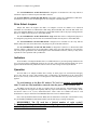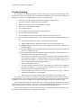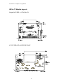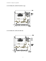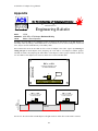
1
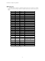
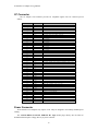
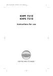
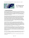
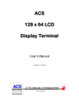
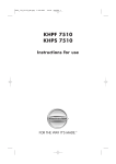
ACS IDE to CF Adapter
Module
User's Manual
Monday, July 03, 2006
6 2 3 3 E . S a w g ra s s R d
S a ra s o t a , F L . 3 4 2 4 0 (9 4 1 )3 7 7 -5 7 7 5 F A X(9 4 1 )3 7 8 -4 2 2 6
www.acscontrol.com
Copyright(c)1998 - 2006 by ACS, Sarasota, FL ALL RIGHTS RESERVED
ACS IDE to CF Adapter User s Manual
Table of Contents
Table of Contents........................................................................................................................... 2
Introduction .................................................................................................................................... 3
Features: .................................................................................................................................................. 3
Installation ............................................................................................................................................... 3
IDE Connector......................................................................................................................................... 4
CF Connector........................................................................................................................................... 5
Power Connector ..................................................................................................................................... 5
Drive Select Jumpers ............................................................................................................................... 6
Indicators ................................................................................................................................................. 6
Operation ................................................................................................................................................. 6
Trouble Shooting ..................................................................................................................................... 7
IDE to CF Module Layouts ..................................................................................................................... 8
Original ACS IDE <-> CFA (Rev #2).............................................................................................. 8
ACS-CF-IDEtoCFA 40 PIN IDE MALE......................................................................................... 8
ACS-CF-IDEtoCFA 40 PIN FEMALE Rt. Angle ........................................................................... 9
ACS-CF-IDEtoCFA 44 PIN SFF IDE Male .................................................................................... 9
CF Card Connector Mechanical ..................................................................................................... 10
Frequently Asked Questions.................................................................................................................. 10
Are the IDEToCFA adaptors UL listed ? ....................................................................................... 10
Can the adaptor be used as a Slave IDE device ?........................................................................... 10
Can the CF card be write protected ? ............................................................................................. 10
Can you use the adaptor to connect a harddrive to a CF only device ?.......................................... 10
Do you have an adaptor that supports 3.3v ? ................................................................................. 10
Does your adaptor support CF card model xxx from manufacturer zzz ?...................................... 11
How to use with an older BIOS requiring Cylinders/Heads/Sectors ?........................................... 11
I can fdisk and format the CF card under DOS, but Linux / Solaris fails to mount the device? .... 11
Is there an industrial grade Compact FLASH card ?...................................................................... 11
What are the dimensions of the ACS-CF-IDEToCFA-xxx ? ......................................................... 11
What is the mating power connector for ACS-CF-IDEToCFA-FRA ? ......................................... 11
Where can I find out about the CF card limited write cycles ? ...................................................... 11
Which Compact FLASH cards support DMA?.............................................................................. 12
Why am I getting spurious or non-operation?................................................................................ 12
Why can I only create a single partition on the CF card with your adaptor ? ................................ 12
Why does Windows XP show some CF cards as 'Removeable' and others as 'Hard Drives' ? ...... 12
Will the "-FRA" version fit into an IDE connector on a motherboard ? ........................................ 12
Appendix....................................................................................................................................... 13
2
ACS IDE to CF Adapter User s Manual
Introduction
Thank you for purchasing the ACS IDE to CF Adapter Module. This device provides low-cost
interfacing of Compact Flash Association CF Cards with IDE / ATA equipped computers.
Features:
The ACS IDE to CF Adapter Module provides the following hardware resources:
CF Standard Type 1/Type 2 Card 50 pin Connector
Four different models:
Original IDE Standard 40 pin 0.1 Male Ribbon Connector (non-SFF)
IDE Standard 40 pin 0.1 Male Ribbon Connector (non-SFF)
IDE 40 pin 0.1 Female Connector (non-SFF, Type 1 only)
SFF IDE Standard 44 pin 0.079 Male Ribbon Connector (SFF)
Drive Select Jumpers
CF Card Power Control
Card Powered Indicator
Card Accessed Indicator
DMA support with DMA capable CF cards
Installation
The ACS IDE to CF Adapter module may be mounted with screws through the appropriate mounting
holes. Note that the plated mounting hole marked MT1 is connected to the Ground on the module. Please
refer to the board outlines at the end of this manual for mounting dimensions. The newer models are
designed for ease of installation with redesigned form factors, mounting holes and additional jumpers. An
optional 3.5 drive mounting plate is available for the IDE Standard model.
The module connects to the host PC in the same way that a hard drive is connected - using an IDE
cable on both SFF and non-SFF male connector models, and powered via a disk drive power cable on nonSFF models. There is also a new model that is designed to plug directly into the IDE connector on the
motherboard.
Be careful to observe the pin numbers and connector orientations that are marked on the board legend.
Pin number 1 is also denoted by the use of a square PCB pad.
The use of a standard 40-conductor IDE cable is mandatory for proper operation with most
motherboards. *
(* The 80-conductor cable was first defined with the original Ultra DMA modes 0, 1 and 2. The cable is
considered "optional" for those modes. However, for any Ultra DMA modes above mode 2, the 80-conductor cable is
mandatory. Since the cable is mandatory for high speed modes, the system has to have some way of knowing it is
installed. This is done by having the /PDIAG:/CBLID signal, carried on pin #34 of the interface, grounded in the
connector that attaches to the motherboard. Since the older 40-conductor cable would not have this pin grounded, by
looking for the grounding on this pin at startup the host can determine if the 80-conductor cable is installed. This may
result in incorrect operation of the ACS IDE to CF Adaptor and the use of 80 conductor cables is not recommended.)
3
ACS IDE to CF Adapter User s Manual
IDE Connector
The IDE connector supports PC compatible signals that allow the ACS IDE to CF Adapter
Module to be connected to widely available PC compatible motherboards. The IDE connector pin-out
follows:
Pin #
1
2
3
4
5
6
7
8
9
10
11
12
13
14
15
16
17
18
19
20
21
22
23
24
25
26
27
28
29
30
31
32
33
SFF Pin #
1
2
3
4
5
6
7
8
9
10
11
12
13
14
15
16
17
18
19
20
21
22
23
24
25
26
27
28
29
30
31
32
33
Name
RESETGND
D7
D8
D6
D9
D5
D10
D4
D11
D3
D12
D2
D13
D1
D14
D0
D15
GND
KEY
DMARQGND
IOWRGND
IORDGND
IORDY
CSELDMACKGND
IRQ
IOCS16A1
34
34
PDIAG
35
36
35
36
A0
A2
37
37
CE1-
38
38
CE2-
39
40
N/A
N/A
N/A
N/A
39
40
41
42
43
44
DASP
GND
+5v Logic
+5v Motor
GND
0=ATA
Notes
TIED to CF pin 43 *
MAY BE FORCED LOW VIA JB1
TIED to CF pin 44 *
Grounded in 80-conductor
cables at the mobo end
LIGHTS RED
WITH IORDLIGHTS RED
WITH IORD-
* = Connections for proposed DMA operation.
4
LED WHEN ACTIVE
or IOWRLED WHEN ACTIVE
or IOWR-
ACS IDE to CF Adapter User s Manual
CF Connector
The CF Adapter Card connector provides CF compatible signals. The CF connector pin-out
follows:
Pin #
1
2
3
4
5
6
7
8
9
10
11
12
13
14
15
16
17
18
19
20
21
22
23
24
25
26
27
28
29
30
31
32
33
34
35
36
37
38
39
40
41
42
43
44
45
46
47
48
49
50
Name
GND
D3
D4
D5
D6
D7
CE1A10
OEA9
A8
A7
VCC
A6
A5
A4
A3
A2
A1
A0
D0
D1
D2
IOIS16CD2CD1D11
D12
D13
D14
D15
CE2VS1IORDIOWRWEIREQVCC
CSELVS2RESETIORDY
INPACKREGDASP
PDIAG
D8
D9
D10
GND
Notes
LIGHTS RED LED WHEN ACTIVE
GROUNDED
GROUNDED
GROUNDED
GROUNDED
GROUNDED
+5VDC
GROUNDED
GROUNDED
GROUNDED
GROUNDED
LIGHTS GREEN LED WHEN ASSERTED WITH CD1
LIGHTS GREEN LED WHEN ASSERTED WITH CD2
NO CONNECTION
TIED TO +5V
+5VDC ONLY
MAY BE FORCED LOW VIA JB1
NO CONNECTION
TIED to IDE DMARQTIED to IDE DMACK-
Power Connector
All ACS IDE to CFA Adapters only require +5vdc. They are designed to use industry standard power
cabling.
The ACS-CF-IDEtoCFA 40 PIN FEMALE Rt. Angle model plugs directly into the Host PC
motherboard and requires a floppy drive style power connector.
5
ACS IDE to CF Adapter User s Manual
The ACS-CF-IDEtoCFA 40 PIN IDE MALE is designed to be mounted in a drive bay and has a
standard 5 ¼ power connector as part of the IDE connector.
The ACS-CF-IDEtoCFA 44 PIN SFF IDE MALE is designed to connect to a 2.5 hard drive IDE chain
and obtains its power via the extended signals on extra four pins of the IDE interface.
Drive Select Jumpers
Jumper JB1 allows the original ACS IDE<->CF Adapter (revision #2) module to be connected
standalone or as the Master in a Master/Slave IDE string. When installed, JB1 forces the IDE CSEL- line
active low indicating that there are no other devices on the IDE channel. This is the proper setting when the
IDE to CF Adapter is the only device on the IDE channel.
The ACS-CF-IDEtoCFA 40 PIN FEMALE Rt. Angle model has no drive configuration jumpers as
it is designed to plug directly into the Host PC s motherboard and be the only device on the IDE chain.
The ACS-CF-IDEtoCFA 40 PIN IDE MALE is designed to be mounted in a drive bay and has
Master (MS), Slave (SL) and Cable-Select (CS) jumpers as part of the IDE connector.
The ACS-CF-IDEtoCFA 44 PIN SFF IDE MALE is designed to connect to a 2.5 hard drive IDE
interface and has a jumper block for selecting Master (MS), Slave (SL) and Cable-Select (CS) operation.
The ATA jumper grounds the same named signal on the extended IDE connector, and may or may not be
required for correct operation with your Host PC.
Indicators
All ACS IDE to CF Adapter Modules have two LED indicators to provide operating feedback to the
user. The Green LED is illuminated whenever the CF card is fully inserted and subsequently has power
applied. The Red LED briefly illuminates whenever the CF card is being accessed by the host PC.
Operation
All ACS IDE to CF Adapter modules have circuitry to detect proper CF card insertion and apply
power only when the card is fully installed. This is indicated by the illumination of the Green LED.
However, the circuitry in the Host PC is not designed for removable IDE device operation while power is
applied.
To avoid damage to the Host PC and/or CF Card, it is strongly recommended
that CF cards are only installed or removed when the power to the system is OFF.
The BIOS in most host PCs are able to recognize the CF cards using the Auto detection feature.
Some early BIOS do not support this capability and may require the manual entry of the Cylinders, Heads
and Sectors values as for a User defined hard drive. These values are available from the CF card
manufacturer or may be obtained via the BIOS IDE detection screen on another host PC.
Once correctly identified to the Host PC BIOS, the CF cards behave exactly like a PC hard drive. They
may be FDISKed, FORMATted and made bootable just like their larger, rotating counterparts.
REMEMBER!!! The CF card has a limited number of write cycles!!!
Performing an OS Plug and Play setup or configuring a swap or page file on the CF
card will rapidly exhaust its usable life.
6
ACS IDE to CF Adapter User s Manual
Trouble Shooting
The ACS IDE to CF Adapter module has circuitry to detect proper CF card insertion and apply power
only when the card is fully installed. This is indicated by illumination of the Green LED. The Red LED
indicates CF card access. If the BIOS hangs on power up, try the following:
1.
Turn power off to the computer in which the CF adapter is being installed
2.
Install the CF adapter on the Primary IDE cable/chain
3.
Make sure the Master jumper is installed on the CF adapter
4.
Insert your CF card into the CF adapter
5.
Power up the computer
6.
Set the CMOS to auto type the Primary Master IDE device
7.
Save the CMOS settings and reboot
8.
See if the BIOS correctly reads the Cylinder, Heads, Sectors from the CF card.
9.
If it can t read the Cylinders, Heads, Sectors, make sure the following happened during power
up:
a.
The Green LED turned on when power was applied to the computer
b.
The Red LED turned on or flashed when the bios was trying to determine is size
If step a doesn t happen, check for power to the CF adapter via the disk drive connector on
non-SFF adapters.
If step a & b happened, but the BIOS still cannot determine the Cylinders, Heads, and
Sectors, try a different CF card
If step a & b happened, and the BIOS determined the Cylinders, Heads, and Sectors, but
the computer will not boot, check the following:
1.
Make sure the CF Card if setup as a hard disk, not a floppy. Some manufactures ship the
cards formatted as floppies. Use fdisk to display and or create a partition on the CF card,
then format the partition. If you have a choice, format the partition using FAT, or
FAT16. Some motherboards will not boot FAT32.
2.
Make sure the partition is active
3.
Try using a different brand of CF card. Some BIOS s need a delay after resetting the
hard drive to identify it. CF cards with SST controllers have a built in delay, to
sometimes better mimic a mechanical hard drive.
4.
Some older BIOS s just will not boot from a CF card, due to its speed. Check the
motherboard manufacture for a newer BIOS.
5.
Make sure you re using a 40 conductor ribbon cable and not an 80 conductor cable.
It is possible to have a defective ACS IDE to CF Adapter, but more likely to have a bad CF card(s), or
incompatible BIOS. If the Green LED flickers when the Red access LED turns on, then the ACS IDE to
CF Adapter CF Card power switching section is bad, and the adapter needs to be returned for repair.
Since Compact Flash cards are consumer price driven, Compact Flash card manufactures use any CF
controller they can buy the cheapest. Just because you re buy brand X compact flash card, doesn t mean
you re getting the same CF controller every time. It can change from production lot to lot.
Because of these unknowns with the compact flash cards, we test each ACS IDE to CF Adapter twice,
once after the manufacturing process, and again before it ships.
7
ACS IDE to CF Adapter User s Manual
IDE to CF Module Layouts
Original ACS IDE <-> CFA (Rev #2)
ACS-CF-IDEtoCFA 40 PIN IDE MALE
8
ACS IDE to CF Adapter User s Manual
ACS-CF-IDEtoCFA 40 PIN FEMALE Rt. Angle
ACS-CF-IDEtoCFA 44 PIN SFF IDE Male
9
ACS IDE to CF Adapter User s Manual
CF Card Connector Mechanical
Frequently Asked Questions
Are the IDEToCFA adaptors UL listed ?
The ACS-CF-IDEToCFA adaptors are themselves not UL Rated. The printed circuit board material that is
used is rated UL94V-0. The other components may or may not be UL listed.
Can the adaptor be used as a Slave IDE device ?
The ACS-CF-IDEToCFA and ACS-CF-IDEToCFA-SFF have jumpers that allow them to be configured as
an IDE Master, IDE Slave or determined by Cable Selection.
The ACS-CF-IDEToCFA-FRA does not have these jumpers as it designed to plug directly into the
motherboard's IDE connector, either primary or secondary, and since it fully occupies the cable slot, it will
always appear as the Master device on that IDE 'chain'.
Can the CF card be write protected ?
Using the ACS-CF-IDEToCFA, the CF cards are operated in 'True-IDE' mode. This mode does not support
write protection. This is identical to a hard drive that also doesn't have write protection. While there is a
'write' signal on the interface, this signal is required in normal read operation to talk to the IDE controller
registers in the device, and cannot be disabled.
Windows XPe provides a Enhanced Write Filter (EWF) component that can map writes to a RAM disk to
protect the contents of a CF card used as a hard drive.
Can you use the adaptor to connect a harddrive to a CF only device ?
While it may be possible, the adaptor is not designed with this in mind. The 'Gender' of the IDE and CF
connectors would be incorrect for starters.
Do you have an adaptor that supports 3.3v ?
This adaptor obtains it's power from the disk drive style Molex power connector on the back edge of the
board. Only the 5v input is used, not the 12v.
If you were to apply 3.3v instead of 5v to the appropriate connector pins, then the adaptor might work for
you. The IDE standard does not specify 3.3v operation, and our adaptors are designed to be compatible.
Note that the IDE interface that you connect the adaptor to must also be 3.3v compatible - we're not aware
of any that are, and most might produce or expect signals that are 5v - which may or may not damage your
CF card compatible device. The adaptor is merely a connector map - the IDE controller and its
functionality is entirely contained within the CF card.
Devices designed to be compatible with the CF card standard are required to be operable at 5v.
10
ACS IDE to CF Adapter User s Manual
Does your adaptor support CF card model xxx from manufacturer zzz ?
The adaptor is merely a connector map. The IDE controller functionality is entirely contained within the
CF card.
To date, we've only found that Lexar CF cards are not compatible with the adaptor. This is because Lexar
has decided to provide undocumented dual functionality on some of the IDE signals to support their USB
cable connection. This is not a supported feature of the CF card standard, and it causes Lexar cards to not
operate properly in these adaptors. Lexar has chosen not to respond to our requests for documentation of
these incompatibilities, so we cannot make our adaptor compliant with their non-standard CF cards.
We have had no problems with Sandisk CF cards - they originated the CF card standard. We recommend
Sandisk cards. Kingston CF cards also work. SimpleTech cards also work.
All the adaptors except the FRA model support Type II CF cards. This is solely a mechanical issue
due to the CF card connector that we use.
How to use with an older BIOS requiring Cylinders/Heads/Sectors ?
You can get a datasheet from the manufacture of the CF card, which should give the specifications of the
logical drive format. An alternative would be to install the adapter with a CF card in a newer computer, and
autotype/autoconfig the drive, write down the C/H/S, and enter this into the drive type 47 of the older
computer.
I can fdisk and format the CF card under DOS, but Linux / Solaris fails to mount
the device?
Linux and Solaris appear to have problems when mounting a device that is labeled as 'removeable'. User's
have informed us that correcting the removabililty of the media fixed their problem. The current Sandisk
product -388 parts support the proposed DMA operation, ship out as removable and will have a
utility to change the bit available for no charge after signing a Source Code License Agreement.
Is there an industrial grade Compact FLASH card ?
The SanDisk Industrial card offerings have been end-of-lifed and replaced by a standard OEM or Ultra II
CF -388 offering. These cards have technology that will allow them to meet almost every customer's
requirements.
What are the dimensions of the ACS-CF-IDEToCFA-xxx ?
The dimensions of the various adaptors are diagrammed in the IDE to CF Layouts section of this manual.
What is the mating power connector for ACS-CF-IDEToCFA-FRA ?
These are availble from Digikey (www.digikey.com)
Catalog page:
http://dkc3.digikey.com/PDF/T052/0098.pdf
Power Connector (0.100" 4 Pos)
Housing:
WM2002-ND or WM2013-ND
Contact:
WM2200-ND or WM1114CT-ND
Where can I find out about the CF card limited write cycles ?
Compact Flash cards use Flash Memory. Flash Memory has a limited number of Erase/Write cycles
~300,000. The controller in the Compact Flash card does wear leveling by spreading out the writes
amongst various 'sectors' in the card to prevent premature wearout of a sector.
11
ACS IDE to CF Adapter User s Manual
Here's a link to the originator of the CF card that discusses how they 'wear level' the flash memory to
optimize card life: http://www.sandisk.com/pdf/oem/WPaperWearLevelv1.0.pdf
Digital cameras write to Compact Flash cards to store their photos. However, if you were to place a
pagefile or swapfile on the Compact Flash card, the intense write activity would very quickly exhaust the
life of the card.
Which Compact FLASH cards support DMA?
The current Sandisk -parts xxx-388 support multi-word DMA and have a utility available from Sandisk
available under Software License Agreement to toggle the ATA Identify Removable Media bit.
Why am I getting spurious or non-operation?
Due to standards compliance issues of both the motherboard (specifically some of the VIA 533Mhz
models) and CF card controller manufacturers, the use of 80-conductor IDE cables may result in spurious
or non-operation of the ACS-CF-IDEToCFA adapters. If you experiance any problems, ACS recommends
that only standard 40-conductor IDE cables of a minimum length be used with this product.
Why can I only create a single partition on the CF card with your adaptor ?
This is entirely determined by the controller on the CF card. The controller returns a bit in the ATA
Identify Device command that labels the media as being 'removeable' or not. Windows XP and Windows
XPe (embedded) do not allow multiple partitions to be created on removeable media. Contact your CF card
vendor about obtaining CF cards that are marked as non-removeable. Sandisk has a utility available under
Software License Agreement that allows the 'removeable' media bit of their card controllers to be changed.
Please contact: Sandisk Steve Larrivee or Dave Beasley Phone: (408) 542-0500
Why does Windows XP show some CF cards as 'Removeable' and others as 'Hard
Drives' ?
This is entirely determined by the controller on the CF card. The controller returns a bit in the ATA
Identify Device command that labels the media as being 'removeable' or not. Windows XP and Windows
XPe (embedded) do not allow multiple partitions to be created on removeable media. Contact your CF card
vendor about obtaining CF cards that are marked as non-removeable. Sandisk has a utility available under
Software License Agreement that allows the 'removeable' media bit of their card controllers to be changed.
Please contact: Sandisk Steve Larrivee or Dave Beasley Phone: (408) 542-0500
Will the "-FRA" version fit into an IDE connector on a motherboard ?
Yes. Look at the picture and drawing of the Female Right Angle "-FRA" version carefully, and notice
where the power connector is located. This is the only constraint. Make sure it will clear nearby
components. Care also needs to be taken, when inserting the adapter into the IDE connector on the
motherboard, that pin #1 on the adaptor mates with pin #1 on the motherboard's IDE connector !
12
ACS IDE to CF Adapter User s Manual
Appendix
62 3 3 E. S aw gr a s s R d
S a r a s o t a , F L . 3 4 2 4 0 ( 9 4 1 ) 3 7 7 - 5 7 7 5 F A X( 9 4 1 ) 3 7 8 - 4 2 2 6
www.acscontrol.com
Engineering Bulletin
DATE:
1/3/06
PRODUCT: ACS IDE to CFA Adaptor Revision #2 Only
TITLE:
Master / Slave Operation
Normally, the ACS IDE to CFA Adaptor revision #2 must be the only device on an IDE Primary or
Secondary chain. By making a small modification, two ACS IDE to CFA revision #2 Adaptors, master and
slave, may be used on an IDE Primary or Secondary chain.
IDE connector Pin 28 on the ACS IDE to CFA revision #2 adaptor is the CSEL- signal. By removing or
cutting this pin on both adaptors, then jumpering one ACS IDE to CFA adaptor as Master (jumper
installed on SNGL) and jumpering the other IDE to CFA adaptor as Slave (jumper installed on MULTI)
two ACS IDE to CFA adaptors can coexist as master/slave on the same IDE chain.
IDE < - > CFA
Copyright(c)1998-2002 by ACS
ALL RIGHTS RESERVED
JB1
Pin 28
SNGL
MULTI
2
40
1
39
MASTER
SLAVE
IDE < - > CFA
IDE < - > CFA
Copyright(c)1998-2002 by ACS
ALL RIGHTS RESERVED
Copyright(c)1998-2002 by ACS
ALL RIGHTS RESERVED
IDE
Controller
Primary or Secondary
JB1
JB1
SNGL
SNGL
MULTI
MULTI
IDE Cable
One caveat - the select LEDs on both adaptors will light whenever either drive on the chain is selected.
13