1
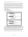
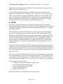
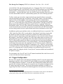
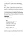
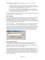
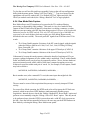
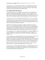
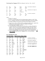
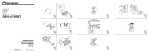
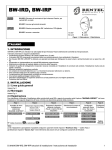
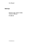
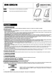
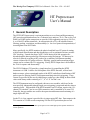
The Moving Pixel Company HTPP User’s Manual – Doc. Rev. 1.20 -- 6/14/05
HT Preprocessor
User’s Manual
1 General Description
The HTPP (HT Preprocessor) is an instrument that serves as front-end Hypertransport
(HT) stream acquisition hardware for a Tektronix logic analyzer (TLA). One or two Tek
P6880 (or P6980) probe connections are provided, each supporting one (up to) 2.8 Gb/s,
8- or 16-bit HT unidirectional link. In conjunction with a TLA, the solution features
filtering, packing, acquisition, and disassembly (i.e. low-level protocol interpretation) of
incoming data from its HT links.
More specifically, the HTPP monitors the physical and link layer HT protocol starting
with bit-time0 identification and data alignment as well as continual real-time periodic
CRC checking. Unused data from CAD15-CAD8 during 8-bit link operation are
discarded and the data repacked for efficient processing and storage. HT data may be
selectively filtered according to HT packet type or arbitrary field pattern-matching
criteria evaluated for HT packet selection. Similarly, general pattern-matching trigger
criteria can be evaluated for TLA triggering. Finally, HTPP output data is forwarded to
the TLA for capture and disassembly.
The HTCtl Windows GUI provides a simple interface for controlling the HTPP
instrument via USB. It allows for field-update of the HTPP firmware, reflects basic
hardware status, selects operational modes of the HTPP, and allows identification of HT
packet types for filtering, and HT field pattern-matching criteria for triggering. These
criteria are specified by the user by identifying a packet type, then filling in desired field
values with binary masks consisting of ‘1’, ‘0’ or ‘X’ for don’t care.
The HTPP instrument may be configured with one or two modules, which are for the
most part fully independent (though simple cross-triggering is supported and they share a
common clock). Each module of the HTPP monitors one HT stream, requires one 136channel TLA module1, has its own USB connection, and is controlled by its own GUI.
Generally, the two modules are used for the upstream and downstream monitoring of a
single duplex HT link.
On the TLA, a bus support is provided for viewing acquired HT data. Data output to the
TLA consists of 136-bit records comprising 128-bits of HT packet data plus several
1
Running at ~200 MHz DDR. Note this speed requires TLA7AXX high-speed acquisition modules for
correct operation.
Page 1 of 23
The Moving Pixel Company HTPP User’s Manual – Doc. Rev. 1.20 -- 6/14/05
control signals such as master clock, valid, and record type bits. In addition to the most
common “Data record” type, which is just packed HT packet data, the HTPP hardware
also outputs CRC records and Special records. The CRC record passes periodic
checksum information extracted from the HT stream, along with valid flags to indicate
successful real-time CRC verification. The Special record encodes custom HTPP
information for the disassembler to use and display including: packet alignment, trigger
information, configured link width, protocol error bits, and sub-sampled values for slow
HT and user signals. Please consult the HTPP TLA Support Users Manual for more
detailed information.
2 HTPP Interfaces
The HTPP has the following interfaces:
Front Panel:
Module 1 (downstream)
- P6880 Connector to HT hardware under test
- Loop-back test connector
- Link reset push button
- Two LED indicators
Module 2 (upstream)
- P6880 Connector to HT hardware under test
- Loop-back test connector
- Link reset push button
- Two LED indicators
Rear Panel:
Line Power
Module 1 (downstream)
- USB Connector (1.1 or 2.0)
- Two 68-channel Samtec connectors to TLA
Module 2 (upstream)
- USB Connector (1.1 or 2.0)
- Two 68-channel Samtec connectors to TLA
As mentioned, each module operates entirely independent from the other. Thus, each has
their own set of connectors and indicators. The loop-back test connectors output a slow
speed (188 MHz DDR) HT test stream useful for HTPP and TLA verification. The reset
push button resets the channel, putting the HTPP module in its power up state, waiting
for a HT cold/warm reset sequence (assuming normal mode of operation – see next
section for more details). LED1 marked “Active” indicates the link is operating correctly
and valid periodic CRCs are being received on the HT link. LED2 marked “Trigger”
indicates when a trigger condition as configured by the HTCtl GUI has occurred.
Page 2 of 23
The Moving Pixel Company HTPP User’s Manual – Doc. Rev. 1.20 -- 6/14/05
3 HTPP Operation
In the following discussion, HTPP refers to one HTPP link module operating in normal
mode (i.e. not in “No CRC” mode, “Raw” mode, or one of the “Bypass” modes in the
Debug menu). After powering on the HTPP hardware, the HTCtl application should be
started and the configuration downloaded to the instrument (via the “Config Send”
button). After power-up, the HTPP waits for an HT cold-reset initialization sequence. At
least one cold-reset is required before HTPP power-up initialization is complete. By the
end of cold-reset, the HTPP has detected bit-time0 and properly aligned incoming data to
32-bit words.
Subsequent cold or warm reset sequences (whether initiated by Reset or LDTStop) are
automatically detected by the HTPP, resetting internal state appropriately. For triggering
purposes, the user may choose to use the link reset push-button on the HTPP or the
“Reset Link” button in the HTCtl GUI to reset the hardware to its “waiting for HT reset”
state (suspending output to the TLA until after the reset sequence is seen).2
Clock speed changes during warm reset are handled automatically by the HTPP. On the
other hand, as the HTPP does not interpret HT configuration register write cycles on the
link, the link width setting is assumed to be whatever the user has indicated the link width
will be after warm reset (using HTCtl). Incorrectly identifying the link width in HTCtl
will result in erroneous operation.
Having identified bit-time0 following HT reset, the HTPP can determine when periodic
CRCs occur in the HT stream and verify that they are correct. As previously mentioned,
periodic CRC information is output to the TLA as separate CRC records. Note that
packet CRC checking (in link retry mode) is not currently supported in the HTPP. The
TLA disassembly will merely identify the packet CRC as HT data words.
The HT input stream to an HTPP module consists of the following 24 signals:
CAD[15..0], Ctl[3..0], PowerOK, Reset, LDTStop, LDTReq, and Usr[3..0]. In 8-bit
links, CAD[15..8] are unused. Due to system bandwidth constraints, the HTPP processes
the HT signals in different ways. The CAD bits are packed into 128-bit records
(stripping CAD[15..8] for 8-bit link widths). For each 128-bit record, only 4 of 16
associated Ctl bits are carried, one for each 32-bit word. With the exception of the CRC
in packet retry mode, all of the Ctl bits associated should be identical. If they are not, this
is an error condition reported to the TLA by the HTPP via the CtlMismatch flag.
The slow HT signals – PowerOK, Reset, LDTStop, and LDTReq – are subsampled at
approximately 15 MHz, which is the output frequency of the Special record. Similarly,
three user signals are supported3, but with additional aggregating logic that allows 188
MHz samples of the signals to be ANDed (for active low signals) or ORed (for active
2
The reset push-button acts as a hard reset and requires a subsequent cold HT reset sequence to complete
re-initialization (as with power on). The ‘Link Reset’ GUI button is a ‘softer’ reset allowing either cold or
warm reset sequences to initiate normal operation.
3
Actually, user signals are currently not supported as of firmware release 1.3. Please contact the Moving
Pixel Company for more information.
Page 3 of 23
The Moving Pixel Company HTPP User’s Manual – Doc. Rev. 1.20 -- 6/14/05
high signals) before output at the 15 MHz rate. The user identifies Usr signals as active
high or active low in the HTCtl GUI.
After the HTPP has initialized and been configured, and a cold reset sequence has
completed, record output to the TLA begins. TLA acquisition, of course, doesn’t begin
until set to run and the TLA trigger state machine conditions have been satisfied. The
next section describes the HTCtl application, including details on setting up HT field
pattern-matching terms for the TLA to use for triggering (see the HTPP TLA support
users manual for more detail on HT data acquisition using the TLA).
4 HTCtl
HTCtl.exe is a Windows application to configure and control the HTPP instrument,
running under Windows 98, ME, NT, 2K, and XP. Install by running Setup.exe off of the
distribution CD ROM, which by default locates the application directory in “C:\Program
Files\TMPC\HTBSP”.
HTCtl communicates with an HTPP module via USB. A multi-port USB mini-hub is
provided for connection to multiple modules within an HTPP and/or multiple HTPP
instruments. Each module has a unique identifying serial number (marked on the HTPP
front panel) that is used by the HTCtl application to select among multiple modules. For
convenience, HTPP modules are labeled “upstream” and “downstream” intended that
they be paired as two unidirectional links of a single, duplex HT link. By convention,
upstream modules have an odd serial number and downstream modules have an even
serial number.
One instance of HTCtl controls one HTPP module. When the application is started, the
USB driver is queried for the serial numbers of HTPP modules connected to the machine
and the results are displayed for the user to select. Once selected, subsequent instances of
HTCtl will not be allowed to acquire the same HTPP module (until the application that
owns it is closed).
After HTCtl acquires the HTPP module, it loads the saved configuration associated with
the serial number from a file located in the application directory. This configuration file
is automatically saved at application exit. In addition, the user may save and restore his
own configuration files using the “File->Save Cfg” or “File->Load Cfg…” menu options.
The main functions of HTCtl are to:
• Configure HT packet filtering based on packet type
• Set up pattern-matching trigger criteria
• Set up operational modes of the HTPP
• Display current HTPP status
• Update HTPP firmware
Each of these functions is described in the following sections.
Page 4 of 23
The Moving Pixel Company HTPP User’s Manual – Doc. Rev. 1.20 -- 6/14/05
Figure 1 – HTCtl Main Window
4.1 HT Packet Filtering
Figure 1 shows the HTCtl main window. This section concerns controls in the frame
labeled “Filter Pkt Types”.
One of the features of the HTPP hardware is the ability to filter HT packets forwarded to
the TLA based on packet type. Because one TLA output record (with 128 HT data bits)
contains multiple HT packets, two filtering cases are possible. The first case is when all
the HT packets in a given record are to be filtered. In this case, the Valid record flag is
simply cleared, causing the TLA not to acquire it. This reduces TLA memory used for
acquisition.
The second filtering case is when only some of the HT packets contained in a TLA record
are to be filtered. Here, the HTPP replaces the Cmd field of filtered packets with a
Page 5 of 23
The Moving Pixel Company HTPP User’s Manual – Doc. Rev. 1.20 -- 6/14/05
reserved Filter Cmd value designated by the user. Using the “Filter Cmd” selection box,
the user designates a HT reserved-HOST value for the HTPP hardware to use for flagging
filtered packets. Filtered packets are not seen by the user and are discarded by the
disassembler. Note that the Filter Cmd value in HTCtl must match the Filter Cmd value
set in the disassembler on the TLA (disassembly options) for correct filtering operation.
To filter certain types of packets, simply check the associated check boxes associated
with the unwanted packet types and click the “Send Config” button. Note that filtering
applies to both extended address control packets and their non-extended address
equivalents. Due to the HTPP’s treatment of HT data words as an independent “packet
type” (i.e. not associating data words with their packet headers)4, filtering a packet type
that has data without also filtering HT data words will leave “orphaned” data in the
disassembler output. However, there should be no ambiguity identifying orphaned data
words from data words associated with a packet of interest (due to the HT restriction that
no intervening packets between a packet header and its data can themselves have data).
In addition to packet types and data words, two additional check boxes are provided. The
“CRC” check box filters CRC records and the “Limit Special” check box requests that
the HTPP not output more than one Special record between unfiltered data records.
Special records are required for packet data alignment so they cannot be entirely filtered.
But using the “Limit Special” function, TLA traces that capture sparse occurrences of a
particular packet type can significantly reduce the number of Special records captured.
The TLA disassembly support also allows removing Special records from the display, but
using this feature does not conserve TLA capture memory. Note that limiting Special
record output also reduces the sub-sampling of slow HT and user signals, so this feature
is not recommended when these signals are important to view. Moreover, in the strange
event that the packet causing the trigger event is filtered (perhaps along with other packet
types), TLA triggering may be delayed waiting for an unfiltered special record to be
output (which won’t happen with the “Limit Special” function enabled until an unfiltered
HT packet is output).
For convenience, the “Set All” and “Clr All” buttons beneath the filter check boxes set all
or clear all of the check boxes respectively.
4.2 Trigger Configuration
Because of the parallel nature and unknown formatting (to the TLA) of the captured data,
triggering on specific values of specific HT packet fields is not generally possible by the
TLA without hardware assistance. To this end, the HTPP hardware and the HTCtl GUI
provides this assistance, allowing the user to specify terms for pattern matching based on
HT packet type and field values. The result of this pattern matching is available as a
trigger flag in the Data record and also latched trigger bits in the Special record for both
4
The main difficulty of associating Hypertransport data words with their control packets is that additional
control packets (with no data) can be interposed between a packet header and its data.
Page 6 of 23
The Moving Pixel Company HTPP User’s Manual – Doc. Rev. 1.20 -- 6/14/05
the upstream and downstream HTPP modules). This represents the most common
method for triggering the TLA.
The pattern-matching trigger criteria are organized essentially as a sum-of-products
equation with up to four terms. Each term corresponds to a collection of packet field
masks, in which the user indicates bits of interest as a ‘0’ or a ‘1’ and bits not of interest
as an ‘X’ (don’t care). 5 The user first chooses a term with the “Prev/Next Term” arrows
and selects a packet type with the “Pkt Type” selection box. This fills in corresponding
fields labels and editable masks for the given packet type for the user to modify. For
convenience, the field masks are initialized from a saved template that records the last
settings for each packet type. All field masks for the current term may be cleared (i.e. set
to don’t care) using the “Clear Masks” button and all terms may be set to ‘unused’ using
the ‘Reset Config’ button.
As a shorthand facility for entering addresses in hexadecimal (rather than binary), the
Addr button is provided. The button always displays the current address mask in
hexadecimal with ‘X’ for don’t care nibbles. Clicking on the button brings up a dialog
allowing the user to change the address mask fill in the HT packet address bits
appropriately. Further bit editing of fields may subsequently be necessary for finer
specification.
When creating new trigger criteria, be sure to check that all terms are set properly (it is
easy to edit only one term and forget about the previous settings of other terms). The
“Pkt Type” for unused terms should be set to “unused”. To enable address extension
fields for the current term, check the “Address Ext” check box. Note that extended
address control packets are considered distinct from their equivalent non-extended
address control packets for triggering purposes. If triggering on both types is desired,
two terms are required, one for each type.
The 2-bit ‘RecType’ group in the TLA disassembly is used to flag Data records that
contain an HT packet that matches the trigger criteria (as well as differentiate Data
records from Special and CRC records). Thus, the TLA will generally be configured to
trigger on (RecType == TRIGGER_DATA). Note that (RecType == TRIGGER_DATA)
does not uniquely identify the HT packet satisfying the trigger criteria. The user must
consider which among eight possible HT packets contained within the record actually
caused the trigger.6
In addition, two trigger bits are latched and forwarded in the Special record to the TLA
and displayed in the ‘Trigger’ disassembly group. Bit 0 (local trigger) and bit 1 (cross
trigger) in the ‘Trigger’ group indicate the latched trigger state of the local and alternate
5
Clearly, the HTPP triggering methodology ideally could be made more powerful, in particular offering
inequality field comparisons, negation, and sequential trigger state machines. Though implementing more
sophisticated triggering is problematic given current logic resource constraints, the Moving Pixel Company
welcomes feedback in order to gauge the practical needs of our customers for future revisions.
6
On the TLA, data records contain 128-bits of HT data, or up to 4 HT packets. Internally, the HTPP
maintains data records containing 256-bits of HT data, or up to 8 HT packets. Thus, the TRIGGER_DATA
record type always appears in pairs on the TLA.
Page 7 of 23
The Moving Pixel Company HTPP User’s Manual – Doc. Rev. 1.20 -- 6/14/05
HTPP modules respectively, i.e. whether at least one HT packet has satisfied its
respective module’s configured trigger criteria since the user last requested trigger reset.
These bits are offered to the user more as trigger status, and are not as useful for TLA
triggering.
The “Wait For Cross Trigger” check box inhibits local triggering until the cross trigger
flag is true. This allows, for example, triggering on the first response packet on the
downstream link following a specific request on the upstream link. Note however,
because of device latency and pipelining there is no implicit guarantee that the triggered
response packet will be the response packet associated with the triggered request packet.
The user must match the UnitID/SrcTag fields to correctly match request/response pairs.
The “Disable Trigger” check box inhibits triggering on the HTPP module. This is
required for setting up cross-triggering scenarios using two HTPP modules and two
HTCtl GUIs. Specifically, triggers need to be disabled on the upstream link until both
the upstream and downstream links have been configured. Then, the “Disable Trigger”
check box is unchecked to re-enable the system. The “Use Trig As Select” check box
replaces filtering by packet type. Instead, only packets that satisfy the trigger criteria are
forwarded to the TLA for disassembly.
Trigger examples:
1) Trigger on IO Port 80 byte write.
Configure the HTCtl GUI as follows:
Term 1:
1) Select the "Write Request" Pkt Type.
2) Set the "Data Length" field = 0 (for byte writes)
3) Set the Addr field to 0xfdfc000050
3a) Set the "Addr[39:32]" field to: '11111101'
3b) Set the "Addr[31:24]" field to: '11111100'
3c) Set the "Addr[23:16]" field to: '00000000'
3d) Set the "Addr[15:8]" field to: '00000000'
3e) Set the "Addr[7:2]" field to: '010100'
Then set up the TLA to trigger on:
Group RecType == TRIGGER_DATA.
2) Trigger on PCI Config write to dev 0, func 0, offset 40h
This is similar to the example above, with the exception that there are two types of HT
Configuration cycles (type 0 and type 1). The two types are distinguished by different
base addresses (0xfdfe000000 and 0xfdff000000) and type 0 cycles use the current bus
rather than use the bus field in the address.
Page 8 of 23
The Moving Pixel Company HTPP User’s Manual – Doc. Rev. 1.20 -- 6/14/05
We can set up the trigger in two ways, with a “don't care” in address bit 24, or with two
terms:
First (easiest) approach:
Term 1:
1) Select the "Write Request" Pkt Type.
2) Set the Addr field to 0xfdf (111X) 000040
2a) Set the "Addr[39:32]" field to: '11111101'
2b) Set the "Addr[31:24]" field to: '1111111X'
2c) Set the "Addr[23:16]" field to: '00000000'
2d) Set the "Addr[15:8]" field to: '00000000'
2e) Set the "Addr[7:2]" field to: '010000'
Second approach:
Term 1:
1) Select the "Write Request" Pkt Type.
2) Set the Addr field to 0xfdfe000040
2a) Set the "Addr[39:32]" field to: '11111101'
2b) Set the "Addr[31:24]" field to: '11111110'
2c) Set the "Addr[23:16]" field to: '00000000'
2d) Set the "Addr[15:8]" field to: '00000000'
2e) Set the "Addr[7:2]" field to: '010000'
Term 2:
1) Select the "Write Request" Pkt Type.
2) Set the Addr field to 0xfdff000040
2a) Set the "Addr[39:32]" field to: '11111101'
2b) Set the "Addr[31:24]" field to: '11111111'
2c) Set the "Addr[23:16]" field to: '00000000'
2d) Set the "Addr[15:8]" field to: '00000000'
2e) Set the "Addr[7:2]" field to: '010000'
In either case, as before, set the TLA to trigger on:
Group RecType == TRIGGER_DATA.
3) Conditionally capture all IO Reads and Write to CMOS registers IO ports 70, 71, 72
and 73.
Triggering and filtering on field ranges can only be done in the HTPP using don't care
bits. Thus, ranges are limited to those aligned and sized as powers of two. Moreover,
writes to specific byte lanes within a double word can only be decoded using the mask
bits contained in the data words following the packet header.
Page 9 of 23
The Moving Pixel Company HTPP User’s Manual – Doc. Rev. 1.20 -- 6/14/05
Since 70-73 maps to 0x46-4a hex, the best we can do is widen the address range to an
aligned power of two, i.e. 0x40-4f, or use two terms to reduce the range to a smaller
superset, i.e. 0x44-0x47 and 0x48-0x4c to span the range 0x44-0x4c. Also, since we
want to capture both both reads and writes, we must use two terms for each aligned
address range.
Set the trigger terms in the HTCtl GUI as follows:
Term 1:
1) Select the "Write Request" Pkt Type.
2) Set the Addr field to 0xfdfc00004 (01xx)
2a) Set the "Addr[39:32]" field to: '11111101'
2b) Set the "Addr[31:24]" field to: '11111100'
2c) Set the "Addr[23:16]" field to: '00000000'
2d) Set the "Addr[15:8]" field to: '00000000'
2e) Set the "Addr[7:2]" field to: '010001'
Term 2:
1) Select the "Write Request" Pkt Type.
2) Set the Addr field to 0xfdfc00004 (10xx)
2a) Set the "Addr[39:32]" field to: '11111101'
2b) Set the "Addr[31:24]" field to: '11111100'
2c) Set the "Addr[23:16]" field to: '00000000'
2d) Set the "Addr[15:8]" field to: '00000000'
2e) Set the "Addr[7:2]" field to: '010010'
Term 3:
1) Select the "Read Request" Pkt Type.
2) Set the Addr field to 0xfdfc00004 (01xx)
2a) Set the "Addr[39:32]" field to: '11111101'
2b) Set the "Addr[31:24]" field to: '11111100'
2c) Set the "Addr[23:16]" field to: '00000000'
2d) Set the "Addr[15:8]" field to: '00000000'
2e) Set the "Addr[7:2]" field to: '010001'
Term 4:
1) Select the "Read Request" Pkt Type.
2) Set the Addr field to 0xfdfc00004 (10xx)
2a) Set the "Addr[39:32]" field to: '11111101'
2b) Set the "Addr[31:24]" field to: '11111100'
2c) Set the "Addr[23:16]" field to: '00000000'
2d) Set the "Addr[15:8]" field to: '00000000'
23) Set the "Addr[7:2]" field to: '010010'
Finally, instead of triggering, we want to capture only records that satisfy the trigger
condition. To do this we check the check box "Use Trig As Select".
Page 10 of 23
The Moving Pixel Company HTPP User’s Manual – Doc. Rev. 1.20 -- 6/14/05
As usual the TLA can be set to trigger on:
Group RecType == TRIGGER_DATA.
4) Trigger on ReadResponse to MMIO readSized to PMIO space, offset 10
This requires setting up a trigger on the upstream link module, followed by a trigger on
the downstream link module. (Here, ‘upstream’ describes the link containing the request
packet and ‘downstream’ describes the link containing the response packet.)
Currently, the cross-triggering capability between HTPP modules is limited to use of the
cross trigger flag, which can be used in the trigger criteria by checking the “Wait For
Cross Trigger” check box. It will be up to the user to match specific upstream request,
downstream response pairs via their UnitID and SrcTag fields. Probably the best way to
limit searching through the downstream trace results is to make use of the "Use Trig As
Select" option to filter the downstream responses.
Upstream Module (master trigger)
Term 1:
1) Select the "Read Request" Pkt Type
2) Set the Addr field to 0xfdfc00000 (10xx)
2a) Set the "Addr[39:32]" field to: '11111101'
2b) Set the "Addr[31:24]" field to: '11111100'
2c) Set the "Addr[23:16]" field to: '00000000'
2d) Set the "Addr[15:8]" field to: '00000000'
23) Set the "Addr[7:2]" field to: '000010'
Set up the upstream TLA module to trigger on:
Group RecType == TRIGGER_DATA
Again, we can only trigger on power-of-two address ranges, so the upstream trigger will
fire on I/O offsets 8-15. If desired, check the "Use Trig As Select" check box to limit the
upstream records captured by the TLA.
Downstream Module (slave trigger)
Term 1:
1) Select the "Read Response" Pkt Type
Check the “Wait For Cross Trigger” check box
Set up the downstream TLA module to trigger on:
Group RecType == TRIGGER_DATA.
Page 11 of 23
The Moving Pixel Company HTPP User’s Manual – Doc. Rev. 1.20 -- 6/14/05
If desired, check the "Use Trig As Select" check box to limit the downstream records
captured by the TLA.
Coordination is required in setting up triggers for both the upstream and downstream
modules. We must first clear and prevent the upstream trigger from occurring until both
modules have been configured. To do this, check the “Disable Trigger” check box on the
upstream module’s HTCtl GUI. Then, proceed to configure the upstream and
downstream modules as described above. Finally, uncheck the “Disable Trigger” check
box to allow triggering to occur.
4.3 Operational Configuration and Control
Other controls in the HTCtl window are described below:
Link Width: These option boxes declare the link width after an HT warm reset
sequence. As the HTPP hardware does not interpret configuration write messages, the
user must specify this setting for correct HTPP operation after warm reset.
Usr Config: These check boxes indicate whether Usr bits are active high or active low.
This information is used to determine the aggregation method of each Usr signal 15 MHz
sub-sampling for output in the Special record. Active high signals undergo logical OR
aggregation. Active low signals undergo logical AND aggregation.
Send Config: This button sends the current configuration including filter and trigger
criteria, link width, and Usr config options to the HTPP module.
Link Reset: This button resets the HTPP module, disabling TLA record output until a
cold or warm HT Reset sequence is seen on the link. Its use is not necessary for correct
operation of the HTPP, as cold and warm reset sequences are automatically detected in
hardware. However, this button can be helpful for capturing staged events on the HT
link, by putting the HTPP in a quiescent state to prevent the TLA from triggering
prematurely.
Trigger Reset: This button clears the latched local and cross trigger flags. Assuming
trigger events are not continually occurring, the Trigger and CrossTrigger GUI status
LEDs will turn red.
4.4 Status Display
Several status LEDs are provided in the HTCtl main window:
• ‘HT Clk’ green indicates transitions are occurring on the input HT clock.
• ‘Bit Time0’ green indicates the HTPP has seen an HT reset sequence and HT data
is passing through the instrument.
• ‘CRC Error’ green indicates no CRC errors have occurred seen since the last HT
link reset or press of the ‘Trigger Reset’ button.
Page 12 of 23
The Moving Pixel Company HTPP User’s Manual – Doc. Rev. 1.20 -- 6/14/05
•
•
‘Trigger’ green indicates the trigger condition has fired since the last HT link
reset or press of the ‘Trigger Reset’ button. The state of this flag is also indicated
by the bit 0 in the Trigger group during the special record.
‘Cross Trigger’ green indicates the trigger condition from the alternate HTPP
module (if present) has fired since the last HT link reset or press of the ‘Trigger
Reset’ button (from the alternate link’s HTCtl GUI).
Link Width indicates the current (assumed) link width based on the link width setting and
whether a warm reset sequence has been seen.
4.5 Self-test
Two options in the Debug menu control the loop-back self-test capability of the HTPP.
Checking the ”Run Self-Test” option starts the internal (low-level) HT generator
outputting data to the self-test connector on the HTPP front-panel. It is intended for loopback connection to the input for self-test validation. Uncheck this option to stop the selftest generator (and uncheck and recheck to restart).
The “Self Test Config…” menu option (Debug menu) is used to determine the data sent
to the front-panel connector. This option brings up the self-test configuration dialog
allowing the user to specify either a playback file (which in turn can be either a high-level
HT file or a low-level pattern file) or check a box to indicate the HTPP should play the
default self-test sequence. Data is output on the self-test connector at about 188 MHz
DDR using the currently selected link width of 8- or 16 bits, and loops repeatedly.
4.5.1 Default Self-Test
The default self-test contains an arbitrary collection of HT packet data, intended to
demonstrate a typical HT listing and validate cable connections and correct box
operation. Obtaining a valid Active light on the front-panel or a Green LED light on the
HTCtl GUI is evidence of correct self-test operation.
The self-test pattern begins first with an HT cold-reset sequence, though due to internal
memory constraints the sequence is not a legal HT reset sequence with very short
PowerOK and Reset# pulses. However, the sequence is sufficient for the HTPP module
to recognize. Second, HT packet data is output, starting with an initial CRC block (512
bit-times) then looping on four subsequent CRC blocks in such a way that the periodic
CRC fields remain valid.
Page 13 of 23
The Moving Pixel Company HTPP User’s Manual – Doc. Rev. 1.20 -- 6/14/05
It should be noted that the HT packets output by the self-test generator, while structurally
legal, are not necessarily meaningful at higher HT protocol layers. For example, packets
are constructed with arbitrary patterns filling the fields. (e.g. the rxNextPacketToAck
field in NOP packets is an incrementing counter and many of the addresses are set to
0x123456789a) and a Sync Packet may arbitrarily show up in the various types of
packets that are output. Please consult the TLA refmem SelfTest.tla included with your
software release to see a trace of the self-test generator output.
4.5.2 High-Level User Self-Test Files
The user may construct his own looping self-test test file with valid HT data as follows.
•
•
•
•
•
•
•
•
•
•
Each line consists of HT Ctl bit (0 or 1) and HT Data (32-bit hex value) separated
by a comma.
The first line must have Ctl set to 1 (for proper identification of bit-time 0)
Null lines are okay
Comment lines are okay if they begin with '#'
Exactly 4 CRC blocks must be provided (pad with NOPs if necessary)
For 8-bit mode, each CRC block is 128 32-bit words
(thus 4*128 = 512 lines total in file)
For 16-bit mode, each CRC block is 256 32-bit words
(thus 4*256 = 1024 lines total in file)
A warm reset sequence will be prepended to the data
Correct periodic CRC bytes will be inserted into data
No control of HT Reset, PowerOK, LDTStop, LDTReq, Usr signals is provided.
To play the user self-test file (and loop repeatedly), bring up the self-test configuration
dialog with the menu option “Debug->Self Test Config…”. Type in or browse for the
appropriate self-test file, uncheck the “Use Default Self-Test” option and click OK.
Check (or uncheck and recheck) the “Debug->Run Self Test” to begin playback.
4.5.3 Low-Level User Self-Test Files
For low-level hardware debugging -- i.e. to validate probe, connector, cabling, and TLA
acquisition capability – self-test files containing rudimentary data patterns may be played
out the self-test connector. These files have the following syntax:
•
•
•
•
•
•
•
The first line has the following string “# TMPC DEBUG”.
Each line contains one 24-bit hex value representing one bit-time
LSB contains CAD7-0
Middle byte contains CAD15-8 (ignored in 8-bit mode)
MSB contains control signals as follows (MS bit to LS bit)
(Usr2, Usr1, Usr0, LDTReq, LDTStop, Reset, PowerOK, Ctl)
An even number of values are required for correct looping.
The maximum number of values is 512.
Page 14 of 23
The Moving Pixel Company HTPP User’s Manual – Doc. Rev. 1.20 -- 6/14/05
To play the user self-test file (and loop repeatedly), bring up the self-test configuration
dialog with the menu option “Debug->Self Test Config…”. Type in or browse for the
appropriate self-test file, uncheck the “Use Default Self-Test” option and click OK.
Check (or uncheck and recheck) the “Debug->Run Self Test” to begin playback.
4.5.4 Raw Mode Data Capture
Raw Mode allows raw HT input data to be passed to the TLA without filtering,
processing, or disassembly (only packing). This mode is a low-level mode for data
capture on the HT link before bit-time0 or when there is a cabling, connector, or other
hardware error preventing valid HT data from being acquired. Because of the bandwidth
limitation between the HTPP and the TLA, only HT clock speeds of up to 600 MHz are
supported in this mode (higher clock rates require use of the debug Bypass modes
described in the next section). The mode packs HT signals from 4 bit-times into 32-bit
words:
•
•
•
TLA Group DataB contains 4 bit-times of the HT control signals, with the signals
ordered as follows (MS bit to LS bit): Usr2, Usr1, Usr0, LDTReq, LDTStop,
Reset, PowerOK, Ctl.
TLA Group DataC contains 4-bit times of the upper HT data byte (CAD15-8)
TLA Group DataD contains 4-bit times of the lower HT data byte (CAD7-0)
Unfortunately, because this mode operates without the benefit of tracking an HT reset
sequence, temporal alignment of bytes within words is undefined. That is, within DataB,
DataC and DataD words, any byte may be temporally earliest. Worse, because hardware
processes internal records with a width of 8 bit-times, temporal wrapping occurs not
within each word, but within each pair of words. So, for example, in one capture, DataD
may look as follows:
0x03020100, 0x07060504, 0x0b0a0908, 0x0f0e0d0c, …
But in another trace (after a manual ECL reset) the same input data might look like:
0x05040302, 0x01000706, 0x0d0c0b0a, 0x09080f0e, …
The user must be aware of this acquisition idiosyncrasy to correctly interpret HT link
activity.
For correct Raw Mode operation, the HTPP needs to be told to ignore the HT link reset
protocol, which in turn resets HTPP hardware (and temporarily disables proper
acquisition). Instead, the user checks the “Debug->Manual ECL Reset Mode” option and
performs a reset manually using the “Debug->Force ECL Reset” option. This only needs
to be performed once when the HTPP is powered on and a valid HT clock is present on
the link. Once the link has manually been reset, the user may put the HTPP hardware in
Raw Mode by selecting the Debug->Raw Mode menu option.
Page 15 of 23
The Moving Pixel Company HTPP User’s Manual – Doc. Rev. 1.20 -- 6/14/05
To most easily view records output in Raw Mode, it is recommended that the “Debug”
disassembly option is set from “Normal” to “No Decode”. This allows the captured
DataB, DataC, and DataD groups containing the packed HT data to be viewed without
erroneous HT disassembly cluttering up the listing window.
4.5.5 Bypass Mode Data Capture
The Bypass modes allow raw HT input data to be passed to the TLA without filtering,
processing, or disassembly (only packing). This mode is a low-level mode for data
capture on the HT link before bit-time0 or when there is a cabling, connector, or other
hardware error preventing valid HT data from being acquired. Unlike Raw Mode, which
requires HT link clocking less than 600 MHz, the Bypass modes can run at any speed.
At high clock speeds, due to the output bandwidth limitation to the TLA, not all signals
from the HT probe can be passed to the TLA at the same time. Instead, using this mode
(or the other two bypass modes) one byte lane of three is packed and output to the TLA
using the DataC and DataD groups. (Note data for internal debugging is present on in the
DataA and DataB groups and should be ignored).
In these modes, each output record to the TLA contains 8 bit-times of the CAD7-0,
CAD15-8, or Ctrl/User signals (depending on which mode is selected). Because these
modes operate without the benefit of tracking an HT reset sequence, temporal alignment
of bytes within a record is undefined. That is, any of the eight byte lanes (of DataC and
DataD groups) may contain the earliest byte in the record. However, the earliest byte
lane will remain fixed within records until the front-panel reset button is pressed, or an
HT reset sequence is seen. Packing uses LSB ordering, so, for example, if DataD[23..16]
is the earliest byte in the record, bytes from subsequent bit-times are: DataD[31..24],
DataC[7..0], DataC[15..8], DataC[23..16], DataC[31..24], DataD[7..0], DataD[15..8],
DataD[23..16].
For correct Bypass mode operation, the HTPP needs to be told to ignore the HT link reset
protocol, which in turn resets HTPP hardware (and temporarily disables proper
acquisition). Instead, the user checks the “Debug->Manual ECL Reset Mode” option and
performs a reset manually using the “Debug->Force ECL Reset” option. This only needs
to be performed once when the HTPP is powered on and a valid HT clock is present on
the link. Once the link has manually been reset, the user may put the HTPP hardware in
Bypass Mode by selecting the “Debug->Bypass Mode CAD[7..0]”, “Debug->Bypass
Mode CAD[15..0]” or “Debug->Bypass Mode Ctrl/User” menu options.
To most easily view records output in Bypass Mode, it is recommended that the “Debug”
disassembly option is set from “Normal” to “No Decode”. This allows the captured
DataC, and DataD groups containing the packed HT data to be viewed without erroneous
HT disassembly cluttering up the listing window.
Page 16 of 23
The Moving Pixel Company HTPP User’s Manual – Doc. Rev. 1.20 -- 6/14/05
4.6 Menus
File->Save Cfg…: Brings up a dialog to save the current configuration. However, this
usually will not be necessary as the current configuration is automatically saved to a file
located in the application directory unique to each serial number when the HTCtl GUI is
closed.
File->Load Cfg…: Brings up a dialog to load a previously saved configuration.
File->Exit: Closes the application.
Control->Program: Brings up the firmware programming dialog, further described
further in the next section.
Config->Use Alt Link Reset: Configures the HTPP link to use the alternate link’s
HTReset and PowerOK signals for initialization. Use when these signals are only
connected for one link direction (upstream or downstream).
Config->Ignore LDTStop: Instructs the HTPP to ignore the LDTStop signal for
resetting the link. Use when LDTStop is unused or not connected.
Debug->No CRC: One of the debugging modes of HTPP operation is ‘No CRC’ mode.
When this option is checked, periodic CRC byte extraction and checking is disabled.
This is only useful for customers who have hardware that disables periodic CRC insertion
into the HT data stream.
Debug->Manual ECL Reset Mode: When checked, disables automatic internal HTPP
reset from being generated from a warm or cold HT reset sequence. This option should
only be checked when operating in Raw Mode or one of the Bypass Modes.
Debug->Force ECL Reset: When in Manual ECL Reset Mode, generates an internal
HTPP reset to resynchronize hardware to the input HT link. This need only be used
when operating in Raw Mode or one of the Bypass Modes. The HT link clock must be
present and less than 600 MHz for the hardware to resynchronize properly.
Debug->Run Self Test: Checking this option starts the internal (low-level) HT
generator outputting data to the self-test connector on the HTPP front-panel. It is
intended for loop-back connection to the input for self-test validation. Valid HT packet
data is output at about 188 MHz DDR using the currently selected link width of 8- or 16
bits. Unchecking this option stops the generator (though the clock remains active). See
the previous section for more details.
Debug->Self Test Config…: Brings up the self-test configuration dialog for playback
configuration.
Debug->Raw Mode: Checking this option puts the HTPP hardware in Raw Mode. See
previous section for more information.
Page 17 of 23
The Moving Pixel Company HTPP User’s Manual – Doc. Rev. 1.20 -- 6/14/05
Debug->Bypass Mode: CAD[7..0]: Checking this options puts the HTPP in Bypass
Mode for HT signals CAD[7..0].
Debug->Bypass Mode: CAD[15..8]: Same as above, except CAD[15..8] signals are
passed to TLA.
Debug->Bypass Mode: Ctrl/User[7..0]: Same as above, except the HT control signals
are passed to TLA. Each byte comprises the following HT signals (msb to lsb):
Usr2, Usr1, Usr0, LDTStop, LDTReset, Reset, PowerOK, Ctl.
Help->About…: Displays the current HTCtl software version, HTPP module serial
number, versions of the instrument’s PLD and FPGA firmware, and any hardware build
options.
4.7 Firmware update
Figure 2 – HTPP Firmware Programming Dialog
The programming dialog is used to upgrade the HTPP firmware in the field. Bring the
dialog up from the main window using the ‘Control->Program…’ menu option. While
this dialog supports password protected features such as programming serial numbers and
encoding firmware files, the only option available to users is programming and verifying
the HTPP.
Page 18 of 23
The Moving Pixel Company HTPP User’s Manual – Doc. Rev. 1.20 -- 6/14/05
To upgrade the firmware of your HTPP instrument, type in or browse for the .htp
firmware file provided by the Moving Pixel Company, and click the program button. The
status bar at the bottom of the window will update the progress of the firmware upgrade.
Click the ‘Done’ button to close the dialog when programming has completed.
5 Appendix A: Probe Pinout for Hypertransport
5.1 Revision History:
Rev 2.3
Rev 2.2
Feb. 23, 2005 Modified timing discussion for edge placement
Feb. 16, 2005 Added a page of timing discussion
Added notes clarifying 8-bit link operation
Added notes about placement of the pads
Re-arranged pinout tables to be more clear for the P6980 probe.
Rev 2.1
April 29, 2004 Added P6980 pins A1, A2 that were inadvertently left off.
Moved Ctl+/- from A16/A17 to A1/A2. Added D8+/D8to A16/A17.
April 23, 2004 Added P6980 pinout.
Added skew tolerance information to Note 7.
Reformatted document
April 13, 2004 Initial Release
Rev 2.0
Rev 1.0
5.2 Pinouts for P6880
Tek Probe Names
Land Sig
Hypertransport Support Names
Head #C3
Head #C2
Head #C1
A15
A14
A13
C/QGND
C/Q+
D[7..0]
LowByteClkND
LowByteClk+
Other sigs
N/A
GND
N/A
D[15..8]
HighByteClkGND
HighByteClk+
B12
B11
B10
D7+
GND
D7-
D7+
GND
D7-
Usr2+
GND
Usr2-
D15+
GND
D15-
Usr2 timed to HighByteClk
A12
A11
A10
D6GND
D6+
D6GND
D6+
Usr1GND
Usr1+
D14GND
D14+
Usr1 timed to HighByteClk
B9
B8
B7
D5+
GND
D5-
D5+
GND
D5-
Usr0+
GND
Usr0-
D13+
GND
D13-
Usr0 timed to HighByteClk
A9
A8
A7
D4GND
D4+
D4GND
D4+
LDTReqGND
LDTReq+
D12GND
D12+
LDTReq timed to HighByteClk
B6
B5
B4
D3+
GND
D3-
D3+
GND
D3-
LDTStop+
GND
LDTStop-
D11+
GND
D11-
LDTStop timed to LowByteClk
Page 19 of 23
The Moving Pixel Company HTPP User’s Manual – Doc. Rev. 1.20 -- 6/14/05
A6
A5
A4
D2GND
D2+
D2GND
D2+
ResetGND
Reset+
D10GND
D10+
Reset timed to LowByteClk
B3
B2
B1
D1+
GND
D1-
D1+
GND
D1-
PwrOK+
GND
PwrOK- D9-
D9+
GND
PwrOK timed to LowByteClk
A3
A2
A1
D0GND
D0+
D0GND
D0+
CtlGND
Ctl+
D8GND
D8+
Ctl timed to LowByteClk
Notes:
1)
2)
3)
4)
5)
Head #C0 is unused.
We have used short hand where Dn by Hypertransport naming is really CADn.
Ctl +/- signals are clocked by the LowByteClk and should be routed accordingly.
LDTStop, LDTReq do not need to be provided for the Support to function.
Signals can be used non-differentially by attaching the signal to the + signal of the
diff pair and tying the negative signal to DC 600mV (HT midrail).
6) UsrN signals are provided for user use!
7) UsrN and LDTStop, LDTReq, Reset, and PwrOK are currently subsampled at
roughly 1/20 bus clock rate before being passed through to the logic analyzer.
However, fine time is maintained in the hardware so that other modes (not yet
defined) can be supported where the signals are used at full time resolution.
8) Note that in 8-bit systems, signals that are labeled “Timed to HighByteClk” will
not be available since there is no “HighByteClock” in an 8-bit system!
5.3 Pinouts for P6980
Tek Probe Names Hypertransport Support Names
Land Sig
Head #C32 Land Sig
Head#C32
A1
A2
A3
A4
A5
A6
A7
A8
A9
A10
A11
A12
A13
A14
A15
A16
A17
A18
A19
A20
D0+
D0GND
D2+
D2GND
D4+
D4GND
D6+
D6GND
NC
NC
GND
D8+
D8GND
D10+
D10-
Ctl+
CtlGND
Reset+
ResetGND
LDTReq+
LDTReqGND
Usr1+
Usr1GND
NC
NC
GND
D0+
D0GND
D2+
D2-
B1
B2
B3
B4
B5
B6
B7
B8
B9
B10
B11
B12
B13
B14
B15
B16
B17
B18
B19
B20
GND
D1D1+
GND
D3D3+
GND
D5D5+
GND
D7D7+
GND
C/QC/Q+
GND
D9D9+
GND
D11-
GND
PwrOKPwrOK+
GND
LDTStopLDTStop+
GND
Usr0Usr0+
GND
Usr2Usr2+
GND
LowByteClk-LowByteClk+
GND
D1D1+
GND
D3-
Page 20 of 23
Ctl timed to LowByteClk
PwrOK timed to LowByteClk
Reset timed to LowByteClk
LDTStop timed to LowByteClk
LDTReq timed to HighByteClk
Usr0 timed to HighByteClock
Usr1 timed to HighByteClock
Usr2 timed to HighByteClock
The Moving Pixel Company HTPP User’s Manual – Doc. Rev. 1.20 -- 6/14/05
A21
A22
A23
A24
A25
A26
A27
GND
D12+
D12GND
D14+
D14GND
GND
D4+
D4GND
D6+
D6GND
B21
B22
B23
B24
B25
B26
B27
D11+
GND
D13D13+
GND
D15D15+
D3+
GND
D5D5+
GND
D7D7+
Notes:
1)
2)
3)
4)
We have used short hand where Dn by Hypertransport naming is really CADn.
Ctl +/- signals are clocked by the LowByteClk and should be routed accordingly.
LDTStop, LDTReq do not need to be provided for the Support to function.
Signals can be used non-differentially by attaching the signal to the + signal of the
diff pair and tying the negative signal to DC 600mV (HT midrail).
5) UsrN signals are provided for user use!
6) UsrN and LDTStop, LDTReq, Reset, and PwrOK are currently subsampled at
roughly 1/20 bus clock rate before being passed through to the logic analyzer.
However, fine time is maintained in the hardware so that other modes (not yet
defined) can be supported where the signals are used at full time resolution.
7) Note that in 8-bit systems, signals that are labeled “Timed to HighByteClk” will
not be available since there is no “HighByteClock” in an 8-bit system!
5.4 Pinouts for P6980
Tek Probe Names Hypertransport Support Names
Land Sig
Head #C10
Land Sig
Head #C10
A1
A2
A3
A4
A5
A6
A7
A8
A9
A10
A11
A12
A13
A14
A15
A16
A17
A18
A19
A20
A21
A22
A23
A24
A25
A26
A27
D0+
D0GND
D2+
D2GND
D4+
D4GND
D6+
D6GND
NC
NC
GND
D8+
D8GND
D10+
D10GND
D12+
D12GND
D14+
D14GND
Unused
Unused
GND
Unused
Unused
GND
Unused
Unused
GND
Unused
Unused
GND
NC
NC
GND
D8+
D8GND
D10+
D10GND
D12+
D12GND
D14+
D14GND
B1
B2
B3
B4
B5
B6
B7
B8
B9
B10
B11
B12
B13
B14
B15
B16
B17
B18
B19
B20
B21
B22
B23
B24
B25
B26
B27
GND
D1D1+
GND
D3D3+
GND
D5D5+
GND
D7D7+
GND
C/QC/Q+
GND
D9D9+
GND
D11D11+
GND
D13D13+
GND
D15D15+
Page 21 of 23
GND
Unused
Unused
GND
Unused
Unused
GND
Unused
Unused
GND
Unused
Unused
GND
HighByteClkHighByteClk+
GND
D9D9+
GND
D11D11+
GND
D13D13+
GND
D15D15+
The Moving Pixel Company HTPP User’s Manual – Doc. Rev. 1.20 -- 6/14/05
Notes:
1)
2)
3)
4)
We have used short hand where Dn by Hypertransport naming is really CADn.
Ctl +/- signals are clocked by the LowByteClk and should be routed accordingly.
LDTStop, LDTReq do not need to be provided for the Support to function.
Signals can be used non-differentially by attaching the signal to the + signal of the
diff pair and tying the negative signal to DC 600mV (HT midrail).
5) UsrN signals are provided for user use!
6) UsrN and LDTStop, LDTReq, Reset, and PwrOK are currently subsampled at
roughly 1/20 bus clock rate before being passed through to the logic analyzer.
However, fine time is maintained in the hardware so that other modes (not yet
defined) can be supported where the signals are used at full time resolution.
7) Note that in 8-bit systems, signals that are labeled “Timed to HighByteClk” will
not be available since there is no “HighByteClock” in an 8-bit system!
5.5 Timing Discussion
The front end of the HTBSP is calibrated for the highest clock and data rate for which it
is designed. This rate is 1.4GHz clock or 2.8G bits per second per pin. The timing
margins at this clock rate are very small. The unit is calibrated expecting the clock and
data transitions to be exactly 90 degrees out-of-phase at the probe points with the goal to
leave as much timing margin to the customer’s target system as possible.
However, in lower speed systems, the designer may allow the system design to consume
some of the margin. For example, if the system clock is known never to be higher than
800 MHz and the designer knows that the receiver will be sampling at on each clock
edge, it may allow the designer to significantly loosen the phase setting requirement of
data and clock edges at the probe points (or source), perhaps putting the timing outside
the sampling window of the HTBSP.
In considering the above discussion, our recommendation for the system design is that the
clock transitions must be at the 90 degree point or later relative to the data transitions.
This will allow the HTBSP to work properly at all clock frequencies. This constraint
must be true after all tolerances, skews, and jitters are accounted for.
There are several methods that can be employed to achieve this result. The clock trace
can be lengthened such that the relationship is true in all cases. In some systems, the
clock phase is adjustable and/or calibrate-able. In those systems, calibrate it such that the
required timing relationship is always true.
It is expected that the designer will minimize the difference in lengths between clocks
and data/control bits in the board layout with the goal being an exact match down to the
thousandth of an inch. We have found that an achievable practical tolerance is +/- 0.010
inch on every trace. In slower systems, this requirement can be loosened somewhat as
long as the timing discussion set forth above is considered. Again, the target should be
Page 22 of 23
The Moving Pixel Company HTPP User’s Manual – Doc. Rev. 1.20 -- 6/14/05
0.000 inches to leave the poor transmitter/receiver/test equipment as much margin as
possible.
We recommend placement of the probe points near the transmitter on each link. If this is
not possible, then the next preferred placement is the probe points near the receiver. The
worst case is placing the probe points in the center of the traces between a transmitter and
a receiver.
If you wish to have a discussion with one of our engineers about this requirement or any
other aspect of the Hypertransport system design and the TMPC HTBSP, please contact
us.
Contact Information:
The Moving Pixel Company
+1.503.626.9663 phone Pacific Time zone
[email protected]
Page 23 of 23