1
Programmer's Manual
Digital Gamma Finder (DGF)
DGF-4C
Version 3.04, January 2004
X-Ray Instrumentation Associates
8450 Central Ave
Newark, CA 94560 USA
Phone: (510) 494-9020; Fax: (510) 494-9040
http://www.xia.com
Disclaimer
Information furnished by XIA is believed to be accurate and reliable. However, XIA assumes
no responsibility for its use, or for any infringement of patents, or other rights of third parties,
which may result from its use. No license is granted by implication or otherwise under the
patent rights of XIA. XIA reserves the right to change the DGF product, its documentation,
and the supporting software without prior notice.
1
2
3
4
5
6
7
Overview ........................................................................................................................ 1
DGF-4C C Driver........................................................................................................... 1
C_Dgf4c_Hand_Down_Names ........................................................................................... 3
C_Dgf4c_Boot_System ....................................................................................................... 5
C_Dgf4c_User_Par_IO ....................................................................................................... 6
C_Dgf4c_Acquire_Data ...................................................................................................... 8
C_Dgf4c_Set_Current_ModChan ..................................................................................... 10
C_Dgf4c_Buffer_IO.......................................................................................................... 11
Options for Compiling DGF-4C C Driver......................................................................... 13
Control DGF-4C Modules via DGF-4C C Driver........................................................ 14
3.1 Initialization ............................................................................................................ 14
3.1.1
Initialize global variables ............................................................................. 14
3.1.2
Boot DGF-4C modules................................................................................. 15
3.2 Setting DSP variables ............................................................................................. 16
3.3 Access spectrum memory or list mode data ........................................................... 18
3.3.1
Access spectrum memory............................................................................. 18
3.3.2
Access list mode data ................................................................................... 19
User Accessible Variables............................................................................................ 21
4.1 Module parameters.................................................................................................. 21
4.2 Channel variables.................................................................................................... 27
4.3 ADC data ................................................................................................................ 38
Control Tasks ............................................................................................................... 39
Appendix A — User supplied DSP code ..................................................................... 43
6.1 Introduction............................................................................................................. 43
6.2 The development environment ............................................................................... 43
6.3 Interfacing user code to XIA’s DSP code............................................................... 43
6.4 The interface ........................................................................................................... 44
6.5 Debugging tools ...................................................................................................... 47
Appendix B — Control DGF-4C modules using CAMAC commands ....................... 48
7.1 CAMAC interface................................................................................................... 48
7.2 Initialization ............................................................................................................ 48
7.3 CAMAC commands................................................................................................ 50
7.4 Using level-1 fast CAMAC data reads ................................................................... 51
7.5 Accessing DSP variables ........................................................................................ 51
7.6 Data acquisition runs and data buffering ................................................................ 51
ii
DGF-4C Programmer’s Manual V3.04
XIA 2004. All rights reserved.
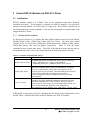
1 Overview
This manual is divided into three major sections. The first section is a description of the
DGF-4C C Driver which is currently used in the DGF-4C Viewer. Advanced users can build
their own user interface using the user accessible functions in the driver. The second section
is a reference guide to program the DGF-4C modules via the C Driver. This will be
interesting to those users who want to integrate the DGF-4C modules into their own data
acquisition system. The third section describes those user accessible variables that control
the functions of the DGF-4C modules. Those advanced and curious users can use this
section to better understand the operation of the DGF-4C. Additionally, this manual also
includes instructions on how to write User DSP code (Appendix A) and to control DGF
modules using CAMAC commands (Appendix B).
The scope of this document is all DGF-4C modules with serial numbers D1100 through
D1199 and E1200 through E1299. Modules with serial numbers E1200 through E1299 have
14-bit ADCs as opposed to the 12-bit ADCs on other modules. Modules with serial numbers
D1100 through D1199 and E1200 through E1299 have 4K FIFOs, which allow storing up to
4096 ADC samples for each channel.
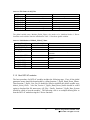
2 DGF-4C C Driver
The DGF-4C C Driver consists of a group of C functions which can be used to configure
DGF modules, make MCA or list mode runs and retrieve data from DGF modules. These
functions can be compiled as a WaveMetrics Igor XOP file which is currently used by the
DGF-4C Viewer, a dynamic link library (DLL) or static library to be used in customized user
interfaces or applications. In order to better illustrate the usage of these functions, an
overview of the operation of DGF is given below and the usage of these functions is
mentioned wherever appropriate.
At first the DGF-4C C Driver needs to be initialized. This is a process in which the names of
system configuration files and variable names are downloaded to the driver. The function
C_Dgf4c_Hand_Down_Names is used to achieve this.
The second step is to boot the DGF modules. It involves downloading all FPGA
configurations and booting the digital signal processor (DSP). It concludes with
downloading all DSP parameters (the instrument settings) and commanding the DSP to
program the FPGAs and the on-board digital to analog converters (DAC). All this has been
encapsulated in a single function C_Dgf4c_Boot_System.
Now, the instrument is ready for data acquisition. The function used for this purpose is
C_Dgf4c_Acquire_Data. By setting different run types, it can be used to start, end or poll a
data acquisition run (list mode run, MCA run, or special task runs like acquiring ADC
traces). It can also be used to retrieve list mode or histogram data from the DGF modules.
1
DGF-4C Programmer’s Manual V3.04
XIA 2004. All rights reserved.
After checking the quality of a MCA spectrum, a DGF user may decide to change one or
more settings like energy filter rise time or flat top. The function used to change DGF
settings is C_Dgf4c_User_Par_IO. This function converts a user parameter like energy
filter rise time in µs into a number understood by the DGF hardware or vice versa.
Another function, C_Dgf4c_Buffer_IO, is used to read data from DSP’s internal memory to
the host or write data from the host into the internal memory. This is useful for diagnosing
DGF modules by looking at their internal memory values. The other usage of this function is
to read, save, copy or extract DGF’s configurations though its settings files.
In a multi-module DGF system, it is essential for the host to know which module and which
channel it is communicating to. The function C_Dgf4c_Set_Current_ModChan is used to
set the current module and channel.
The detailed description of each function is given below.
2
DGF-4C Programmer’s Manual V3.04
XIA 2004. All rights reserved.
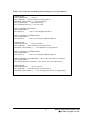
C_Dgf4c_Hand_Down_Names
Syntax
long C_Dgf4c_Hand_Down_Names (
char *Names[],
// An array containing the names to be downloaded
char *Name);
// A string indicating the type of names (file or
// variable names) to be downloaded
Description
Use this function to download file or variable names from host user interface to the DGF-4C
C driver. The driver needs these file names so that it can read the DGF hardware
configurations from the files stored in the host computer and download these configurations
to the DGF. The variable names are used by the driver to obtain the indices of DSP variables
when the driver converts user variable values into DSP variable values or vice versa.
Parameter description
Names is a two dimensional string array containing either the file names or the variable
names. It can be one of the following four sets of names whose selection depends on the
other parameter Name:
1. All_Files is a string array which has (MAX_NUMBER_OF_MODULES+5)
elements. Currently MAX_NUMBER_OF_MODULES is defined as 24. The first
five elements of All_Files are the name of system FPGA file, DSP code binary file,
DSP I/O parameter values file, DSP code I/O variable names file, and DSP code
memory variable names file. The remaining elements are FIPPI file names for each
module. All file names should contain the complete path name. Note: all modules use
the same system FPGA and DSP codes, but could use different FIPPI files. An
example of All_Files is given in Table 3.2.
2. Module_Global_Names is a string array containing global variable names which are
applicable to all modules, e.g. number of modules in the crate, the CAMAC controller
type, the SCSI number, and the CAMAC crate ID, etc. Module_Global_Names
currently can hold 64 names. If less than 64 names are needed (which is the current
case), the remaining names should be defined as empty strings. A detailed
description of Module_Global_Names is given in Table 3.6.
3. Global_Data_Names is a string array containing global variable names which are
applicable to each individual module, e.g. module number, module CSR, coincidence
pattern, and run type, etc. Global_Data_Names can currently hold 64 names. If less
than 64 names are needed (which is the current case), the remaining names should be
defined as empty strings. A detailed description of Global_Data_Names is given in
Table 3.6.
3
DGF-4C Programmer’s Manual V3.04
XIA 2004. All rights reserved.
4. User_Var_Names is a string array containing variable names which are applicable to
individual channels of individual modules, e.g. channel CSR, filter rise time, filter flat
top, voltage gain, and DC offset, etc. User _Var_Names currently can hold 64 names.
If less than 64 names are needed (which is the current case), the remaining names
should be defined as empty strings. A detailed description of User_Var_Names is
given in Table 3.6.
Name is a string variable used to select which set of names to be handed down. It can be one
of the following four choices: “ALL_FILES”, “MODULE_GLOBAL_NAMES”,
“GLOBAL_DATA_NAMES”, or “USER_VAR_NAMES”.
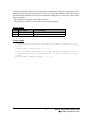
Return values
Value Description Error Handling
0
-1
Success
Invalid name
None
Check the second parameter Name
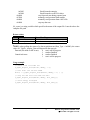
Usage example
// download module global names; define Module_Global_Names first
C_Dgf4c_Hand_Down_Names(Module_Global_Names, "MODULE_GLOBAL_NAMES");
// download global data names; define Global_Data_Names first
C_Dgf4c_Hand_Down_Names(Global_Data_Names, "GLOBAL_DATA_NAMES");
// download user variable names; define User_Var_Names first
C_Dgf4c_Hand_Down_Names(User_Var_Names, "USER_VAR_NAMES");
// download file names; define All_Files first
C_Dgf4c_Hand_Down_Names(All_Files, "ALL_FILES");
4
DGF-4C Programmer’s Manual V3.04
XIA 2004. All rights reserved.
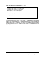
C_Dgf4c_Boot_System
Syntax
long C_Dgf4c_Boot_System (
long Boot_Pattern);
// The DGF boot pattern
Description
Use this function to boot all DGF modules in the system. Before booting the modules, it
initializes the CAMAC communication port, and if CAMAC Master is going to be used,
loads the CAMAC station number register.
Parameter description
Boot_Pattern is a bit mask used to control the boot pattern of DGF modules:
Bit 0: Boot system FPGA
Bit 1: Boot FIPPI
Bit 2: Boot DSP
Bit 3: Load DSP parameters
Bit 4: Apply DSP parameters (call Set_DACs and Program_FIPPI)
Under most of the circumstances, all the above tasks should be executed to initialize the DGF
modules, i.e. the Boot_Pattern should be 0x1F.
Return values
Value Description Error Handling
0
<0
Success
Boot failed
None
Check the error message reported by the driver
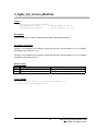
Usage example
// boot DGF-4C modules
ret = C_Dgf4c_Boot_System(0x1F);
if(ret < 0)
// error handling
5
DGF-4C Programmer’s Manual V3.04
XIA 2004. All rights reserved.
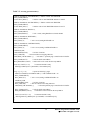
C_Dgf4c_User_Par_IO
Syntax
long C_Dgf4c_User_Par_IO (
double *User_Par_Values,
char *User_Par_Name,
long direction);
//
//
//
//
//
//
A double precision array containing the
user parameters to be transferred
A string variable which designates
which type of user parameters to be
transferred
Transfer direction (read or write)
Description
Use this function to transfer user parameters between the user interface, driver and DSP’s I/O
memory. Some of these parameters are applicable to all DGF modules in the system, like
CAMAC Controller ID or SCSI Bus number. Other parameters are applicable to either a
DGF module (independent of its four channels), e.g. coincidence pattern, or any of the four
channels in a DGF module, e.g. energy filter settings. For those parameters which need to be
transferred to or from DSP’s internal memory (other parameters such as number of modules
are only used by the driver), this function calls another function UA_PAR_IO which first
converts these parameters into numbers that are recognized by both the DSP and the driver
then performs the transfer.
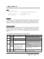
Parameter description
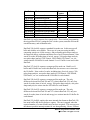
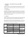
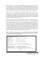
User_Par_Values is a double precision array containing the parameters to be transferred.
Depending on another input parameter User_Par_Name, different User_Par_Values array
should be used. Totally three User_Par_Values arrays should be defined and all of them are
one-dimensional arrays. The corresponding relationship between User_Par_Values and
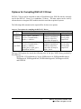
User_Par_Name is listed in Table 2.1.
Table 2.1: The Combination of User_Par_Name and User_Par_Values.
User_Par_Name
User_Par_Values
Name
Size
Module_Global_Values 64
MODULE_GLOBAL_NAMES
GLOBAL_DATA_NAMES
Global_Data_Values
SYNCH_WAIT or IN_SYNCH
Element of array User_Var_Names User_Values
64×24
Data Type
Double precision
Double precision
64×24×4 Double precision
The way to fill the User_Values array is to fill the channel first then the module. First 64
values are stored in the array for channel 0, and then repeat this for other three channels. At
that time, 64×4 values have been filled for module 1. Then repeat this for the remaining
6
DGF-4C Programmer’s Manual V3.04
XIA 2004. All rights reserved.
modules. For the Global_Data_Values array, first store 64 values for module 1, and then
repeat this for other modules.
User_Par_Name is a string variable which selects what type of parameters to be transferred.
It can be one of the following four choices:
1. MODULE_GLOBAL_NAMES: used to transfer parameters applicable to all
modules.
2. GLOBAL_DATA_NAMES: used to transfer parameters applicable to individual
modules.
3. SYNCH_WAIT and IN_SYNCH: used to broadcast SYNCH_WAIT or IN_SYNCH
to all modules.
4. Element of array User_Var_Names (see Table 3.1): used to transfer parameters
applicable to an individual channel of an individual module.
direction indicates the transfer direction of parameters:
0 - download (write) parameters from the user interface to the driver;
1 - upload (read) parameters from the driver to the user interface.
Return values
Value Description
0
<0
Error Handling
Success
None
Transfer failed Check the error message reported by the driver
Usage example
// set global data variable MODULE_CSRA to 0x2400
Global_Data_Values[Find_Xact_Global_DATA_Match(“MODULE_CSRA”)]=0x2400;
// download MODULE_CSRA to DSP
C_Dgf4c_User_Par_IO(Global_Data_Values, " GLOBAL_DATA_NAMES", 0);
// set user variable ENERGY_RISETIME to 6.0 µs
User_Var_Values[Find_Xact_User_Match (“ENERGY_RISETIME”)]=6.0;
// download ENERGY_RISETIME to DSP
C_Dgf4c_User_Par_IO(User_Var_Values, “ENERGY_RISETIME”, 0);
7
DGF-4C Programmer’s Manual V3.04
XIA 2004. All rights reserved.
C_Dgf4c_Acquire_Data
Syntax
long C_Dgf4c_Acquire_Data (
long Run_Type,
unsigned int *User_data,
char *file_name);
//
//
//
//
//
Data acquisition run type
An unsigned 32-bit integer array
containing the data to be transferred
Name of the file used to store list
mode or histogram data
Description
Use this function to acquire ADC traces, MCA spectrum, or list mode data. The string
variable file_name needs to be specified when stopping a MCA run or list mode run in order
to save the data into a file, or when calling those special list mode runs to retrieve list mode
data from a saved list mode data file. In all other cases, file_name can be specified as an
empty string. The unsigned 32-bit integer array User_data is only used for acquiring ADC
traces (control task 0x4), reading out list mode data or MCA spectrum. In all other cases,
User_data can be any unsigned integer array with arbitrary size. Make sure that User_data
has the correct size and data type before reading out ADC traces, list mode data, or MCA
spectrum.
Parameter description
Run_Type is a 16-bit word whose lower 12-bit specifies the type of either data run or control
task run and upper 4-bit specifies actions (start\stop\poll) as described below.
Lower 12-bit:
0x100,0x101,0x102,0x103
0x200,0x201,0x202,0x203
0x301
0x1 - 0x15
0x3
0x4
list mode runs
fast list mode runs
MCA run
control task runs
adjust offsets
acquire ADC traces
Upper 4-bit:
0x1000
0x2000
0x3000
0x4000
0x500x
0x5000
0x5001
0x5002
start new run
resume run
stop run and automatically store spectrum data
poll
list mode special runs
Parse list mode data file
Locate list mode traces
Read list mode traces
8
DGF-4C Programmer’s Manual V3.04
XIA 2004. All rights reserved.
0x5003
0x5004
0x6000
0x7000
0x8000
0x9000
Read list mode energies
Read list mode event PSA values
stop list mode run during repeated runs
manually read spectrum from module
manually read spectrum from a MCA file
stop any data run
file_name is a string variable which specifies the name of the output file. It needs to have the
complete file path.
Return values
Value Description
∗
0
<0
Error Handling
Success
None
Data acquisition failed Check the error message reported by the driver
∗
NOTE: when polling the status of a data acquisition run (Run_Type = 0x4000), the return
value of C_Dgf4c_Acquire_Data will depend on the run type:
Data run (list mode or MCA run):
0
run is still in progress
1
run has finished
Control task runs:
0
run has finished
1
run is still in progress
Usage example
// start a new list mode run
C_Dgf4c_Acquire_Data(0x1100, dummy, “ ”);
// wait until the run has ended
while( ! C_Dgf4c_Acquire_Data(0x4100, dummy, “ ”) ) {;}
// stop run and save list mode run data
C_Dgf4c_Acquire_Data(0x6100, dummy, file_name_1);
// store energy histogram
C_Dgf4c_Acquire_Data(0x3100, dummy, file_name_2);
9
DGF-4C Programmer’s Manual V3.04
XIA 2004. All rights reserved.
C_Dgf4c_Set_Current_ModChan
Syntax
long C_Dgf4c_Set_Current_ModChan (
unsigned short Module,
// Module number to be set
unsigned short Channel);
// Channel number to be set
Description
Use this function to set the current module number and channel number.
Parameter description
Module is an unsigned 16-bit integer which specifies the current module to be set. Module
should be in the range of 1 to 23.
Channel is an unsigned 16-bit integer which specifies the current channel to be set. Channel
should be in the range of 0 to 3.
Return values
Value Description
0
<0
Error Handling
Success
None
Failed to set module or channel number Check the error message reported by the driver
Usage example
// Set current module to 1 and current channel to 3
C_Dgf4c_Set_Current_ModChan(1, 3);
10
DGF-4C Programmer’s Manual V3.04
XIA 2004. All rights reserved.
C_Dgf4c_Buffer_IO
Syntax
long C_Dgf4c_Buffer_IO (
unsigned short *Values,
//
//
unsigned short type,
//
unsigned short direction, //
char *file_name);
//
An unsigned 16-bit integer array
containing the data to be transferred
Data transfer type
Data transfer direction
File name
Description
Use this function to: 1) download or upload DSP parameters between the user interface and
the DGF modules; 2) save DSP parameters into a settings file or load DSP parameters from a
settings file and applies to all modules present in the system; 3) copy parameters from one
module to others or extracts parameters from a settings file and applies to selected modules.
Parameter description
Values is an unsigned 16-bit integer array used for data transfer between the user interface
and DGF modules. type specifies the I/O type. direction indicates the data flow direction.
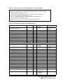
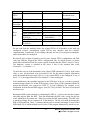
The string variable file_name contains the name of settings files. Different combinations of
the three parameters - Values, type, direction – designate different I/O operations as listed in
Table 2.2.
Table 2.2: Different I/O operations using function C_Dgf4c_Buffer_IO.
Type
0
1
2
Direction
0
1
0*
1
0
1
0
3
1
4
N/A***
Values
DSP I/O variable values
Values to be written
All DSP variable values
N/A**
Values[0] – source module
number; Values[1] – source
channel number; Values[2] –
copy/extract pattern bit mask;
Values[3], Values[4], … destination channel pattern
Values[0] – address; Values[1] –
length
11
I/O Operation
Write DSP I/O variable values to modules
Read DSP I/O variable values from modules
Write to certain locations of the data memory
Read all DSP variable values from modules
Save current settings in all modules to a file
Read settings from a file and apply to all
modules
Extract settings from a file and apply to
selected modules
Copy settings from a source module to
destination modules
Specify the location and number of words to be
written into the data memory
DGF-4C Programmer’s Manual V3.04
XIA 2004. All rights reserved.
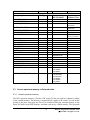
*
Special care should be taken for this I/O operation since mistakenly writing to some locations of the
data memory will cause the system to crash. The Type 4 I/O operation should be called first to specify
the location and the number of words to be written before calling this one. If necessary, please contact
XIA for assistance.
**
Any unsigned 16-bit integer array could be used here.
***
Direction can be either 0 or 1 and it has no effect on the operation.
Return values
Value Description
0
<0
Error Handling
Success
None
I/O operation failed Check the error message reported by the driver
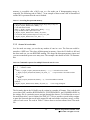
Usage example
// Download DSP parameters to the current DGF module; DSP_Values is a
// pointer pointing to the DSP parameters; no need to specify file name
// here.
C_Dgf4c_Buffer_IO(DSP_Values, 0, 0, “”);
// Read DSP memory values from the current DGF module; Memory_Values is
// a pointer pointing to the memory block; no need to specify file name
// here.
C_Dgf4c_Buffer_IO(Memory_Values, 1, 1, “”);
12
DGF-4C Programmer’s Manual V3.04
XIA 2004. All rights reserved.
Options for Compiling DGF-4C C Driver
DGF-4C C Driver can be compiled as either a WaveMetrics Igor XOP file which is currently
used in the DGF-4C Viewer, or a standalone C-Library. The latter option can be used by
advanced users to integrate DGF modules into their own data acquisition systems.
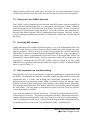
The following table summarizes the required files for these two options.
Table 2.3: Two options for compiling the DGF-4C C Driver.
Compilation
Option
Required Files
C header files
boot.h, Camacdll.h,
globals.h, sharedfiles.h,
utilities.h, Libcc32.h,
vpcic32d.h, Winaspi.h
boot.h, Camacdll.h,
globals.h, sharedfiles.h,
utilities.h, Libcc32.h,
vpcic32d.h, Winaspi.h,
dgf4c_iface.h
C source files
Standalone
C-Library
boot.c, camac.c, camacdll.c,
CC32.c, Communication.c,
dgf4c_c.c, utilities.c
Igor XOP
boot.c, camac.c, camacdll.c,
CC32.c, Communication.c,
dgf4c_c.c, utilities.c,
dgf4c_iface.c, dgf4c_igor.c,
Dgf4cWinCustom.rc
Library files
pcicc32_ni.lib,
pcicc32_ni.dll,
wnaspi32.dll
pcicc32_ni.lib,
pcicc32_ni.dll,
wnaspi32.dll
The Igor XOP option also needs the following files in the Igor XOP Library provided by
WaveMetrics.
IgorXOP.h, VCExtraIncludes.h, Xop.h, XOPResources.h, XOPStandardHeaders.h,
XOPSupport.h, XOPSupportWin.h, XOPWinMacSupport.h, XOPSupport x86.lib,
and IGOR.lib.
13
DGF-4C Programmer’s Manual V3.04
XIA 2004. All rights reserved.
3 Control DGF-4C Modules via DGF-4C C Driver
3.1
Initialization
DGF-4C modules sitting in a CAMAC crate can be initialized using those functions
described in Section 2. As an example, we assume two DGF-4C modules – one revision-D
and one revision-E module – sit in slot 3 and 11, respectively. The CAMAC controller sits in
slot 24 functioning as a master controller. Users are also encouraged to read the sample code
shipped with the C Driver.
3.1.1 Initialize global variables
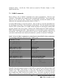
As discussed in Section 2, we assume that three global variable arrays have been defined:
Module_Global_Values, Global_Data_Values and User_Values. For these three global
variable arrays, we also need to define three global name arrays: Module_Global_Names,
Global_Data_Names and User_Var_Names, respectively. Table 3.1 lists the names
contained in each of these name arrays. The order of placing these names into the array is
not important since the C Driver uses search functions to locate each name at run time.
Table 3.1: Contents of Global Name Arrays.
Array
Module_Global_Names
Global_Data_Names
User_Var_Names
Names
NUMBER_MODULES, CONTROLLER_ID, SCSI_BUS, CRATE_ID,
CAMAC_MASTER, FAST_CAMAC, LAM_ENABLE,
C_LIBRARY_RELEASE, C_LIBRARY_BUILD, SLOT_WAVE
MODULE_NUMBER, MODULE_CSRA, MODULE_CSRB,
MODULE_FORMAT, MAX_EVENTS, COINCIDENCE_PATTERN,
ACTUAL_COINCIDENCE_WAIT, MIN_COINCIDENCE_WAIT,
SYNCH_WAIT, IN_SYNCH, RUN_TYPE, BUFFER_HEAD_LENGTH,
EVENT_HEAD_LENGTH, CHANNEL_HEAD_LENGTH,
OUTPUT_BUFFER_LENGTH, NUMBER_EVENTS, RUN_TIME,
DECIMATION
CHANNEL_CSRA, CHANNEL_CSRB, ENERGY_RISETIME,
ENERGY_FLATTOP, TRIGGER_RISETIME, TRIGGER_FLATTOP,
TRIGGER_THRESHOLD, VGAIN, VOFFSET, TRACE_LENGTH,
TRACE_DELAY, PSA_START, PSA_END, EMIN, BINFACTOR, TAU,
BLCUT, XDT, BASELINE_PERCENT, CFD_THRESHOLD,
MULTIPLICITY_PULSE_WIDTH, LIVE_TIME, INPUT_COUNT_RATE
Additionally, a string array All_Files containing the file names for the initialization is also
needed. Table 3.2 lists the file names needed to initialize two DGF-4C modules.
14
DGF-4C Programmer’s Manual V3.04
XIA 2004. All rights reserved.
Table 3.2: File Names in All_Files.
All_Files
All_Files[0]
All_Files[1]
All_Files[2]
All_Files[3]
All_Files[4]
All_Files[5]
All_Files[6]
File Name
Note
C:\XIA\DGF4C\Firmware\dgf4c.bin
C:\XIA\DGF4C\DSP\DGFcodeE.bin
C:\XIA\DGF4C\Configuration\test.itx
C:\XIA\DGF4C\DSP\DGFcodeE.var
C:\XIA\DGF4C\DSP\DGFcodeE.lst
C:\XIA\DGF4C\Firmware\fdgf4c4D.bin
C:\XIA\DGF4C\Firmware\fdgf4c4E.bin
System FPGA configurations
DSP code
Settings file
File of DSP I/O variable names
File of DSP memory variable names
FIPPI configuration for Module 1 (Rev. D)
FIPPI configuration for Module 2 (Rev. E)
The global variable array, Module_Global_Values, also needs to be initialized before C Driver
functions can be called to start the initialization. Table 3.3 lists those global variables.
Table 3.3: Initialization of Module_Global_Values.
Module_Global_Names
NUMBER_MODULES
CONTROLLER_ID
SCSI_BUS
CRATE_ID
Module_Global_Values
Note
2
0
0
1
CAMAC_MASTER
FAST_CAMAC
1
0
LAM_ENABLE
SLOT_WAVE[0]
SLOT_WAVE[1]
SLOT_WAVE[2]
0
24
3
11
The total number of DGF-4C modules
0: J73A, 1: CC32, 2: offline
Usually 0 or 1; could be 0 to 7
The crate number on the front panel dial of the
controller
1: enable, 0: disable; use master controller
1: enable, 0: disable; use level-1 fast CAMAC
transfer
1: enable, 0: disable; use LAM interrupt
CAMAC master controller
Module 1 sits in slot 3
Module 2 sits in slot 11
3.1.2 Boot DGF-4C modules
The boot procedure for DGF-4C modules includes the following steps. First, all the global
parameter names should be downloaded by calling function C_Dgf4c_Hand_Down_Names.
Then function C_Dgf4c_User_Par_IO should be called to initialize the global variable array
Module_Global_Values. After that, function C_Dgf4c_Hand_Down_Names should be called
again to download the file name array All_Files. Finally, function C_Dgf4c_Boot_System
should be called to boot the modules. The following code is an example showing how to
boot the DGF-4C modules using the C Driver functions.
15
DGF-4C Programmer’s Manual V3.04
XIA 2004. All rights reserved.
Table 3.4: An Example Code Illustrating How to Boot DGF-4C Modules.
// download module global names
C_Dgf4c_Hand_Down_Names(Module_Global_Names, "MODULE_GLOBAL_NAMES");
// download global data names
C_Dgf4c_Hand_Down_Names(Global_Data_Names, "GLOBAL_DATA_NAMES");
// download user variable names
C_Dgf4c_Hand_Down_Names(User_Var_Names, "USER_VAR_NAMES");
// initialize module global values
C_Dgf4c_User_Par_IO(Module_Global_Values, "MODULE_GLOBAL_VALUES", 0);
// download file names
C_Dgf4c_Hand_Down_Names(All_Files, "ALL_FILES");
// boot DGF-4C modules
C_Dgf4c_Boot_System(0x1F);
// set current module and channel number
C_Dgf4c_Set_Current_ModChan(1,0);
3.2
Setting DSP variables
The host computer communicates with the DSP by setting and reading a set of variables
called DSP I/O variables. These variables, totally 416 unsigned 16-bit integers, sit in the first
416 words of the data memory. The first 256 words, which store input variables, are both
readable and writeable, while the remaining 160 words, which store pointers to various data
buffers and run summary data, are only readable. The exact location of any particular
variable in the DSP code will vary from one code version to another. To facilitate writing
robust user code, we provide a reference table of variable names and addresses with each
DSP code version. Included with your software distribution is a file called DGFcodeE.var. It
contains a two-column list of variable names and their respective addresses. Thus you can
write your code such that it addresses the DSP variables by name, rather than by fixed
location.
It should come as no surprise that many of the DSP variables have meaningful values and
ranges depending on the values of other variables. A complete description of all
interdependencies can be found in Section 4. All of these interdependencies have been taken
care of by the DGF-4C C Driver. So instead of directly setting DSP variables, users only
need to set the values of those global variables defined in Table 3.1. The C Driver will then
convert these values into corresponding DSP variable values and download them into the
DSP data memory. On the other hand, if users want to read out the data memory, the C
Driver will first convert these DSP values into the global variable values. The code shown in
Table 3.5 is an example of setting DSP variables through the C Driver. Table 3.6 gives a
complete description of all the global variables being used by the DGF-4C C Driver.
16
DGF-4C Programmer’s Manual V3.04
XIA 2004. All rights reserved.
Table 3.5: An Example Code to Illustrating How to Set DSP Variables.
// set global data variable MODULE_CSRA to 0x2400
Global_Data_Values[Find_Xact_Global_DATA_Match(“MODULE_CSRA”)]=0x2400;
// download MODULE_CSRA to DSP
C_Dgf4c_User_Par_IO(Global_Data_Values, " GLOBAL_DATA_NAMES", 0);
// set user variable ENERGY_RISETIME to 6.0 µs
User_Var_Values[Find_Xact_User_Match (“ENERGY_RISETIME”)]=6.0;
// download ENERGY_RISETIME to DSP
C_Dgf4c_User_Par_IO(User_Var_Values, "ENERGY_RISETIME", 0);
Table 3.6: Descriptions of Global Variables in DGF-4C.
Module_Global_Names
I/O Type
Unit
Corresponding DSP
Variables
Legal Range of
Variable Values
NUMBER_MODULES
Read/Write
N/A
N/A
CONTROLLER_ID
SCSI_BUS
CRATE_ID
CAMAC_MASTER
FAST_CAMAC
LAM_ENABLE
C_LIBRARY_RELEASE
C_LIBRARY_BUILD
SLOT_WAVE
Read/Write
Read/Write
Read/Write
Read/Write
Read/Write
Read/Write
Read only
Read only
Read/Write
N/A
N/A
N/A
N/A
N/A
N/A
N/A
N/A
N/A
N/A
N/A
N/A
N/A
N/A
N/A
N/A
N/A
N/A
[1, Max # of
Modules)
Check Controller
Check SCSI bus
Check Crate
0 or 1
0 or 1
0 or 1
N/A
N/A
N/A
Global_Data_Names
I/O Type
Unit
Corresponding DSP
Variables
Legal Range of
Variable Values
MODULE_NUMBER
Read only
N/A
MODNUM
MODULE_CSRA
MODULE_CSRB
MODULE_FORMAT
MAX_EVENTS
COINCIDENCE_PATTERN
ACTUAL_COINCIDENCE_WAIT
MIN_COINCIDENCE_WAIT
SYNCH_WAIT
IN_SYNCH
RUN_TYPE
BUFFER_HEAD_LENGTH
EVENT_HEAD_LENGTH
CHANNEL_HEAD_LENGTH
OUTPUT_BUFFER_LENGTH
NUMBER_EVENTS
Read/Write
Read/Write
Read/Write
Read/Write
Read/Write
Read/Write
Read only
Read/Write
Read/Write
Write only
Read only
Read only
Read only
Read only
Read only
N/A
N/A
N/A
N/A
N/A
N/A
N/A
N/A
N/A
N/A
N/A
N/A
N/A
N/A
N/A
RUN_TIME
Read only
s
MODCSRA
MODCSRB
MODFORMAT
MAXEVENTS
COINCPATTERN
COINCWAIT
COINCWAIT
SYNCHWAIT
INSYNCH
RUNTASK
BUFHEADLEN
EVENTHEADLEN
CHANHEADLEN
LOUTBUFFER
NUMEVENTSA,
NUMEVENTSB
RUNTIMEA,
RUNTIMEB,
RUNTIMEC
[1, Max # of
Modules)
N/A
N/A
N/A
N/A
[0, 65535]
N/A
N/A
0 or 1
0 or 1
0x100, … 0x301
6
3
9, 4, 2
8192
N/A
17
N/A
DGF-4C Programmer’s Manual V3.04
XIA 2004. All rights reserved.
DECIMATION
Read only
User_Var_Names
I/O Type Unit Corresponding
DSP Variables
Legal Range of
Variable Values
CHANNEL_CSRA
CHANNEL_CSRB
ENERGY_RISETIME
Read/Write
Read/Write
Read/Write
N/A
N/A
µs
CHANCSRA
CHANCSRB
SLOWLENGTH
ENERGY_FLATTOP
Read/Write
µs
SLOWGAP
TRIGGER_RISETIME
TRIGGER_FLATTOP
TRIGGER_THRESHOLD
Read/Write
Read/Write
Read/Write
µs
µs
N/A
FASTLENGTH
FASTGAP
FASTTHRESH
N/A
N/A
Depends on
decimation
Depends on
decimation
[0.025, 0.775]
[0, 0.75]
[0,
VGAIN
VOFFSET
TRACE_LENGTH
TRACE_DELAY
PSA_START
PSA_END
EMIN
BINFACTOR
TAU
Read/Write
Read/Write
Read/Write
Read/Write
Read/Write
Read/Write
Read/Write
Read/Write
Read/Write
V/V
V
µs
µs
µs
µs
N/A
N/A
µs
BLCUT
XDT
BASELINE_PERCENT
CFD_THRESHOLD
MULTIPLICITY_PULSE_WIDTH
LIVE_TIME
Read/Write
Read/Write
Read/Write
Read/Write
Read/Write
Read only
N/A
µs
%
%
25 ns
s
INPUT_COUNT_RATE
Read only
cps
GAINDAC
TRACKDAC
TRACELENGTH
TRIGGERDELAY
PSAOFFSET
PSALENGTH
ENERGYLOW
LOG2EBIN
PREAMPTAUA,
PREAMPTAUB
BLCUT
XWAIT
BASELINEPERCENT
CFDTHR
FTPWIDTH
LIVETIMEA,
LIVETIMEB,
LIVETIMEC
FASTPEAKSA,
FASTPEAKSB,
FASTPEAKSC,
LIVETIMEA,
LIVETIMEB,
LIVETIMEC
3.3
N/A
DECIMATION
1, 2, 3, 4, 5, 6
4095/FASTLENGTH]
(0, 16]
(-3, 3)
[0, 100]
[0, 100)
(0, 100)
(0, 100)
[0, 32768)
1, 2, 3, 4, 5, 6
N/A
N/A
>= 0.075
(0, 100)
(0, 100)
[1, 65535]
N/A
N/A
Access spectrum memory or list mode data
3.3.1 Access spectrum memory
The MCA spectrum memory is fixed to 32K words (24 bits per word) per channel, residing
in the external memory. The memory is organized into 8 pages of 4K words. To read out the
spectra to the host, each page has first to be transferred from the external memory to the
linear I/O buffer in the DSP memory, and then read out by a DMA transfer. The Spectrum
18
DGF-4C Programmer’s Manual V3.04
XIA 2004. All rights reserved.
memory is accessible after a MCA run, or a list mode run if histogramming energy is
requested. The following code in Table 3.7 is an example of how to start a MCA run and read
out the MCA spectrum after the run is finished.
Table 3.7: Accessing the spectrum memory.
// start a MCA run; dummy is an unsigned 32-bit integer array of any size
C_Dgf4c_Acquire_Data(0x1301, dummy, “ ”);
// wait until run has ended
while( ! C_Dgf4c_Acquire_Data(0x4301, dummy, “ ”) ) {;}
// stop run and save MCA spectrum to a file
C_Dgf4c_Acquire_Data(0x3301, dummy, file_name);
// read out the MCA spectrum and put it to array User_data
C_Dgf4c_Acquire_Data(0x7301, User_data, “ ”);
3.3.2 Access list mode data
In a list mode run setup, you can do any number of runs in a row. The first run would be
started as a NEW run. This clears all histograms in memory. Once the I/O buffer is full and
has been read out, you can RESUME running. This keeps the histogram memory intact and
you can accumulate spectra over many runs. The example code shown in Table 3.8 illustrates
this.
Table 3.8: Command sequence for multiple list mode runs in a row.
C_Dgf4c_Acquire_Data(0x1100, dummy, “ ”);
// start a new list mode run
k = 1; // initialize counter
do{
while( ! C_Dgf4c_Acquire_Data(0x4100, dummy, “ ”) ) {;} // wait until run has ended
C_Dgf4c_Acquire_Data(0x6100, dummy, file_name_1);
// stop run and save list mode run data
k ++;
if(k > Nruns)
break;
C_Dgf4c_Acquire_Data(0x2100, dummy, “ ”)); // issue ResumeRun command
}while(1);
C_Dgf4c_Acquire_Data(0x3100, dummy, file_name_2);
// store energy histogram
The list mode data in the I/O buffer can be written in a number of formats. User code should
access three DSP variables BUFHEADLEN, EVENTHEADLEN, and CHANHEADLEN in
the settings file of a particular run to navigate through the data set. To facilitate the access of
list mode data after a run is finished, the DGF-4C C Driver provides several utility routines
to parse the list mode data saved in the output file and read out the waveform, energy, or PSA
values of each event. The code in Table 3.9 shows how to read waveforms from a list mode
file.
19
DGF-4C Programmer’s Manual V3.04
XIA 2004. All rights reserved.
Table 3.9: An Example Code Showing How to Access List Mode Data.
C_Dgf4c_Acquire_Data(0x1100, dummy, “ ”); // start a new list mode run
while( ! C_Dgf4c_Acquire_Data(0x4100, dummy, “ ”) ) {;} // wait until run has ended
C_Dgf4c_Acquire_Data(0x6100, dummy, file_name_1); // store list mode data in a file
C_Dgf4c_Acquire_Data(0x3100, dummy, file_name_2); // store energy histogram in a file
C_Dgf4c_Acquire_Data(0x5100, listmodewave, file_name_1); // parse list mode file
totaltraces = 0;
for(i=0; i<2; i++)
totaltraces += listmodewave[i+24]; // sum the total number of traces for the two modules
traceposlen = (long)malloc(totaltraces*3*4); // allocate memory to hold position and length information
C_Dgf4c_Acquire_Data(0x5001, traceposlen, file_name_1); // locate traces
Trace0 = (unsigned short)malloc(traceposlen[1]+2); // allocate memory to hold the first trace
Trace0[0] = traceposlen[0]; // position of the first trace
Trace0[1] = traceposlen[1]; // length of the first trace
C_Dgf4c_Acquire_Data(0x5002, Trace0, file_name_1); // read out the first trace and put it into trace0
20
DGF-4C Programmer’s Manual V3.04
XIA 2004. All rights reserved.
4 User Accessible Variables
User parameters are stored in the data memory space of the on-board DSP. The organization
is that of a linear memory with 16-bit words. Subsequent memory locations are indicated by
increasing addresses. The data memory space, as seen by the host computer, starts at 0x4000.
There are two sets of user-accessible parameters. 256 words in data memory are used to store
input parameters. These can and must be set properly by the user application. A second set of
160 words is used for results furnished by the DGF-4C module. These should not be
overwritten.
As of this writing the start address for the input parameter block is InParAddr=0x4000 and
for the output parameter block it is OutParAddr=0x4100, i.e. the two blocks are contiguous
in memory space. We provide an ASCII file named DGFcodeE.var which contains in a 2column format the offset and name of every user accessible variable. We suggest that user
code use this information to create a nameÆaddress lookup table, rather than relying on the
parameters retaining their address offsets with respect to the start address.
The input parameter block is partitioned into 5 subunits. The first contains 64 data that
pertain to the DGF-4C as a whole. It is followed by four blocks of 48 words, which describe
the settings of the four channels.
Below we describe the module and channel parameters in turn. Where appropriate, we show
how a variable can be viewed using the DGF-4C Viewer.
The DGF-4C C Driver function used to write or read these parameters is
C_Dgf4c_User_Par_IO, and the corresponding DSP parameters to the user-defined global
variables are listed in Table 3.6.
4.1
Module parameters
MODNUM: Logical number of the module. This number will be written into the header of
the I/O buffer to aid offline event reconstruction.
MODCSRA: Module Control and Status Register A. The viewer panel is the Module
CSRA Edit Panel. This is a bit-oriented variable.
Bit 0:
Write data to the circular Level-1 buffer. In this mode data are first being
written into a 2048 word deep buffer. Results, but not traces, are written to
the linear I/O buffer. This mode is useful when only the results from pulse
shape analyses, but not the traces, are requested.
21
DGF-4C Programmer’s Manual V3.04
XIA 2004. All rights reserved.
Note that since software revision 2.60, the RUNTASK variable determines
which buffer is the intermediate buffer in a run.
Bit 1..9:
Reserved.
Set to 0.
Bit 10,13: Bitmask for switchbus settings, for revision-D and revision-E DGF-4Cs only.
These bits are stored in DSP memory, but have to be written to the ICSR
register by the host computer to set the FET switches for proper trigger line
termination. Refer to Table 9.7 in Section 9.3 of the DGF User’s Manual for
application details.
To terminate the fast trigger bus line with 100 Ω set bit 10 of the ICSR. To
terminate the event trigger (dsp trigger) bus line with 100 Ω set bit 13 of the
ICSR.
Bit 11..12 Reserved
Bit 14..15: Reserved.
MODCSRB: Module Control and Status Register B. This is a bit-oriented variable.
Bit 0:
If set, user written DSP code is called.
Bit 1..15:
Reserved. Set to 0.
MODFORMAT: List mode data format descriptor. Currently it is not in use.
SUMDAC:
The value of this variable controls the SUMDAC digital to analog converter.
It can be used to set a trigger threshold on either the multiplicity or the sum
analog signal from any combination of the four input channels. See the user's
manual for the required jumper settings.
The threshold in volt can be calculated as follows:
Threshold = ((32768 - SUMDAC) / 32768)*3.0V
RUNTASK: This variable tells the DGF what kind of run to start in response to a run start
request. Nine run tasks are currently supported.
22
DGF-4C Programmer’s Manual V3.04
XIA 2004. All rights reserved.
RunTask
Mode
0
256 (0x100)
257 (0x101)
258 (0x102)
259 (0x103)
512 (0x200)
513 (0x201)
514 (0x202)
515 (0x203)
769 (0x301)
Slow control run
Standard list mode
Compressed list mode
Compressed list mode
Compressed list mode
Standard fast list mode
Compressed fast list mode
Compressed fast list mode
Compressed fast list mode
MCA mode
Trace
Capture
N/A
Yes
Yes
Yes
Yes
No
No
No
No
No
CHANHEADLEN
N/A
9
9
4
2
9
9
4
2
N/A
RunTask 0 is used to request slow control tasks. These include programming
the trigger/filter FPGAs, setting the DACs in the system, transfers to/from the
external memory, and calibration tasks.
RunTask 256 (0x100) requests a standard list mode run. In this run type all
bells and whistles are available. The scope of event processing includes
computing energies to 16-bit accuracy, and performing pulse shape analyses
for improved energy resolution and better time of arrival measurements. Nine
words of results, including time of arrival, energy, XIA pulse shape analysis,
user pulse shape analysis, GSLTtimeA, GSLTtimeB, GSLTtimeC, etc. are
written into the I/O buffer for each channel. Level-1 buffer is not used in this
RunTask.
RunTask 257 (0x101) requests a compressed list mode run. Both Level-1
buffer and I/O buffer are used in this RunTask, but no traces are written into
the I/O buffer. Nine words of results, including time of arrival, energy, XIA
pulse shape analysis, user pulse shape analysis, GSLTtimeA, GSLTtimeB,
GSLTtimeC, etc. are written into the I/O buffer for each channel.
RunTask 258 (0x102) requests a compressed list mode run. The only
difference between RunTask 258 and 257 is that in RunTask 258, only four
words of results (time of arrival, energy, XIA pulse shape analysis, user pulse
shape analysis) are written into the I/O buffer for each channel.
RunTask 259 (0x103) requests a compressed list mode run. The only
difference between RunTask 259 and 257 is that in RunTask 259, only two
words of results (time of arrival and energy) are written into the I/O buffer for
each channel.
RunTask 512 (0x200) employs the same internal data format as RunTask 256,
but omits buffer-full checks and trace capture. The run is stopped when the
required number of events (MaxEvents) has been acquired. This run type uses
the shortest possible interrupt routine for raw data gathering. Hence, it allows
23
DGF-4C Programmer’s Manual V3.04
XIA 2004. All rights reserved.
for the shortest time between two logged events. For best results the channel
variables PAFLength and TriggerDelay should be set to 1 for all channels
involved, i.e. the trace length for each channel should be set to 0 and bit 10 of
ChanCSRA (described in Section 4.2) for each channel should be cleared.
Level-1 buffer is not used in this run type. Nine words of results, including
time of arrival, energy, XIA pulse shape analysis, user pulse shape analysis,
GSLTtimeA, GSLTtimeB, GSLTtimeC, etc. are written into the I/O buffer for
each channel. However, values of XIA pulse shape analysis and user pulse
shape analysis are meaningless due to no trace capture.
RunTask 513 (0x201) requests a compressed fast list mode run without trace
capture. Both Level-1 buffer and I/O buffer are used in this RunTask. Nine
words of results, including time of arrival, energy, XIA pulse shape analysis,
user pulse shape analysis, GSLTtimeA, GSLTtimeB, GSLTtimeC, etc. are
written into the I/O buffer for each channel. However, values of XIA pulse
shape analysis and user pulse shape analysis are meaningless due to no trace
capture.
RunTask 514 (0x202) requests a compressed fast list mode run. The only
difference between RunTask 514 and 513 is that in RunTask 514, only four
words of results (time of arrival, energy, XIA pulse shape analysis, user pulse
shape analysis) are written into the I/O buffer for each channel. However,
values of XIA pulse shape analysis and user pulse shape analysis are
meaningless due to no trace capture.
RunTask 515 (0x203) requests a compressed fast list mode run. The only
difference between RunTask 515 and 513 is that in RunTask 515, only two
words of results (time of arrival and energy) are written into the I/O buffer for
each channel.
RunTask 769 (0x301) requests a MCA run. The raw data stream is always
sent to the Level-1 buffer, independent of MODCSRA. The data-gathering
interrupt routine fills that buffer with raw data, while the event processing
routine removes events after processing. If the interrupt routine finds the
Level-1 buffer to be full, it will ignore events until there is room again in the
buffer. The run will not abort due to buffer-full condition. This run type does
not write data to the I/O buffer. The module variable MAXEVENTS should
be set to zero, to avoid early run termination due to a MAXEVENTSexceeded condition.
The RunTask can be chosen as the run type in the Run tab of the DGF-4C
Viewer.
CONTROLTASK: Use this variable to select a control task. Consult the control tasks
section of this manual for detailed information. The control task will be
launched when you issue a run start command with RUNTASK=0.
24
DGF-4C Programmer’s Manual V3.04
XIA 2004. All rights reserved.
MAXEVENTS: The module ends its run when this number of events has been acquired. In
the DGF-4C Viewer, MAXEVENTS is automatically calculated when a run
mode is chosen from the run type pulldown menu. The calculation is based
on the trace lengths set by the user. Set MaxEvents=0 if you want to switch
off this feature, e.g., when logging spectra (done automatically in an MCA
mode run).
COINCPATTERN: In the DGF-4C Viewer, the user can request that certain
coincidence/anticoincidence patterns are found for the event to be accepted.
With four channels there are 16 different hit patterns, and each can be
individually selected or marked for rejection by setting the appropriate bit in
the COINCPATTERN mask.
Consider the 4-bit hit pattern 1010. The two 1's indicate that channel 3 (MSB)
and channel 1 have reported a hit. Channels 2 and 0 did not. The 4-bit word
reads as 10(decimal). If this hit pattern qualifies as an acceptable event, set bit
10 in the COINCPATTERN to 1. The 16 bit in COINCPATTERN cover all
combinations. Setting COINCPATTERN to 0xFFFF causes the DGF to
accept any hit pattern as valid.
In the DGF-4C Viewer this variable can be set in the Coincidence Pattern Edit
Panel reachable through the Settings tab by clicking on Edit next to the Coinc.
Pattern entry.
COINCWAIT: Duration of the coincidence time window in 25ns clock ticks. The actual
coincidence window is 50ns wider than the value determined by
COINCWAIT. For this feature to work, bit no. 1 of the ChannelCSRA of the
involved channels should be cleared. This ensures that the DSP can at the end
of the coincidence window suppress further hits reporting by late channels.
In the DGF-4C Viewer this bit is set or cleared in line 1 of the Channel CSRA
Edit Panel. The line has the title "Measure individual live time". Make sure it
is unchecked, so the DSP globally controls FPGA triggering and live time
measurements.
When acquiring long waveforms it may be necessary to delay DSP data
reading to ensure that the FIFOs will contain valid data. Secondly, when
using 6-bit decimation in the FPGA, the minimum value for COINCWAIT is
larger than 1 in all circumstances. Use the following formula to determine
COINCWAIT:
CW[ch] = PEAKSEP[ch] * 2^Decimation; ch=0 to 3
CWmax = MIN 35 * 2^ Decimation, MAX (CW [ch])
ch = 0 − >3
(
ch = 0 − > 3
25
)
DGF-4C Programmer’s Manual V3.04
XIA 2004. All rights reserved.
CWmin =
MAX (0, MIN (CW [ch]))
ch = 0 − > 3
ch = 0 − >3
COINCWAIT = MAX (1, (CW max − CW min) )
SYNCHWAIT: Controls run start behavior. When set to 0 the module simply starts or
resumes a run in response to the corresponding request. When set to 1,
closing the Busy--Synch loop is required. For a single module this is
accomplished by connecting the Busy output to the Synch input via a Lemo
cable. If two or more modules are in the system and are to run synchronously,
a more complex wiring scheme is needed. All Busy outputs must lead to the
inputs of a multi-input OR. The result from the OR operation must be fed
back to the Synch inputs. This kind of set up in connection with SyncWait=1
will ensure that the last module ready to actually begin data taking will start
the run in all modules. And the first module to end the run will stop the run in
all modules. This way it never happens that a multi-DGF system is only
partially active.
INSYNCH:
InSynch is an input/output variable. It is used in multi-DGF systems in which
the modules are driven by a common clock. When InSynch is 1, the module
assumes it is in synch with the other modules and no particular action is taken
at run start. If this variable is 0, then all system timers are cleared at the
beginning of the next data acquisition run (RunTask>0). Using the BusySynch loop as described above, the timers are reset when the entire system
actually starts the run. After run start, InSynch is automatically set to 1.
Clock resetting can occur only if the Busy--Synch loop is closed.
HOSTIO:
A 4 word data block that is used to specify command options. Currently it is
only used to
- specify the channel in an external memory transfer;
- specify the channel when reading untriggered traces;
- specify the channel for baseline measurements.
XdatLength: Length of a data block to be downloaded from the host. Use XdatLength=0 as
the default value for normal operation.
USERIN:
A block of 16 input variables used by user-written DSP code.
U00:
Many unused, but reserved, data blocks have names of the structure Unn.
Those unused data blocks which reside in the block of input parameters for
each channel are called UNUSEDA and UNUSEDB.
UNUSEDA: Only used in Controltask 4 for reading untriggered traces. UNUSEDA stores
the weight in the geometric-weight averaging scheme to remove higher
frequency signal and noise components. The value is calculated as follows:
For a given dt (in µs), calculate the integer intdt = dt/0.025
26
DGF-4C Programmer’s Manual V3.04
XIA 2004. All rights reserved.
Then, if intdt>=11, XWAIT=4*floor((intdt-3)/4)+3
Finally, UNUSEDA = floor( 65536/((intdt-3)/4) )
If intdt<11, UNUSEDA is ignored.
4.2
Channel variables
All channel-0 variables end with "0", channel-1 variables end with "1", etc. In the following
explanations the numerical suffix has been removed. Thus, e.g., CHANCSRA0 becomes
CHANCSRA, etc.
CHANCSRA: The control and status register bits switch on/off various aspects of the
DGF-4C operation; see the Channel CSRA Edit Panel reachable through the
Settings tab of the DGF-4C Viewer. In general, setting the bit activates the
option in question.
Bit 0:
Respond to group triggers only.
Set this bit if you want to control the waveform acquisition for non-triggering
channels by a triggering master channel. For this option to work properly
choose one channel as the master and have its Trigger_Enable bit set. All
dependent channels should have their Trigger_Enable bit cleared. Set bit 0 in
all slave channels. You should also set it in the master channel to ensure
equal time of arrivals for the fast trigger signal, which is used to halt the
FIFOs.
Bit 1:
Measure individual live time.
Keep this bit cleared when operating with master and slave channels, or when
making coincidence measurements using single modules. Set this bit when
measuring independent spectra, i.e., when list mode data are not required.
Bit 2:
Good channel.
Only channels marked as good will contribute to spectra and list mode data.
Bit 3:
Read always
Channels marked as such will contribute to list mode data, even if they did not
report a hit. This is most useful when acquiring induced signal waveforms on
spectator electrodes, i.e., electrodes that did not collect any net charge, but
only saw a transient induced signal.
Bit 4:
Enable trigger.
Set this bit for channels that are supposed to contribute to an event trigger.
Bit 5:
Trigger positive.
Set this bit to trigger on a positive slope; clear it for triggering on a negative
27
DGF-4C Programmer’s Manual V3.04
XIA 2004. All rights reserved.
slope. The trigger/filter FPGA can only handle positive signals. The DGF
handles negative signals by inverting them immediately after entering the
FPGA.
Bit 6:
GFLT.
Set this bit if you want to validate or veto events using the front panel GFLT
LEMO input. When the bit is cleared, the GFLT input is ignored. When set,
the event is accepted only if validated. To be validated, the GFLT input must
be a logic 1 no later than an energy filter rise time after the signal arrival, and
must remain at logic 1 level until a rise time + flat top after signal arrival.
Bit 7:
Histogram energies.
Set this bit to histogram energies from this channel in the on-board MCA
memory.
Bit 8:
Reserved.
Set to 0.
Bit 9:
Reserved.
Bit 10:
Compute constant fraction timing.
This pulse shape analysis computes the time of arrival for the signal from the
recorded waveform. The result is stated in units of 1/256th of a sampling
period (25ns). Time zero is the start of the waveform.
Bit 11:
Enable contribution to multiplicity.
Any of the four channels can contribute to the multiplicity output at the front
panel. With this bit one can switch this contribution on or off.
Bit 12..15: Reserved.
CHANCSRB: Control and status register B.
Bit 0:
If set, call user written DSP code.
Bit 1:
If set, all words in the channel header except Ndata, trigtime and energy will
be overwritten with the contents of URETVAL. Depending on the run type,
this allows for 6, 2 or 0 user return values in the channel header.
Bit2..15: are reserved. Set to 0.
The following two data words are used to set the on-board DACs for this channel. Once a
new variable has been written to DSP memory the DACs have to be reprogrammed by
starting a run with RunTask=0 and ControlTask=0.
28
DGF-4C Programmer’s Manual V3.04
XIA 2004. All rights reserved.
GAINDAC: This DAC is used to program the variable gain amplifier. The GainDAC
value corresponds to a gain according to the following formula.
Gain [V/V] = 0.1639 * 10^((65535 - GAINDAC) / 32768)
TRACKDAC:This DAC determines the DC-offset voltage. The offset can be calculated
using the following formula:
Offset [V] = 3.0 * ((32768 - TRACKDAC) / 32768)
U02:
Begin of a reserved data block.
The following block of data contains trigger/filter FPGA data. Once a new variable has been
written to DSP memory it has to be activated by starting a run with RunTask 0 and
ControlTask 5.
SLOWLENGTH: The rise time of the energy filter depends on SlowLength:
RiseTime = SlowLength * 2^Decimation * 25ns
SLOWGAP: The flat top of the energy filter depends on SlowGap:
FlatTop = SlowGap * 2^Decimation * 25ns.
There is a constraint concerning the sum value of the two parameters:
SlowLength + SlowGap < 32
FASTLENGTH: The rise time of the trigger filter depends on FastLength:
RiseTime = FastLength * 25ns.
Note the constraint: FastLength < 32
FASTGAP:
The flat top of the trigger filter depends on FastGap:
FlatTop = FastGap * 25ns.
There is a constraint concerning the sum value of the two parameters:
FastLength + FastGap < 32
FASTADCTHR: This value is used by the previous versions of DGF-4C Viewer to store
the fast trigger threshold in ADC units. The DGF-4C module does not use
this value.
29
DGF-4C Programmer’s Manual V3.04
XIA 2004. All rights reserved.
For revision-D and revision-E modules one LSB of this variable corresponds
to 4 LSB of the reported waveform data, which are 14-bit numbers.
For DGF-4C Viewer 3.00 or later, this value is not in use any more.
FASTTHRESH: This is the trigger threshold used by the trigger/filter FPGA. The value
relates to a trigger threshold through the formula:
FASTTHRESH = TriggerThreshold * FASTLENGTH
The TriggerThreshold can be set on the Settings tab of the DGF-4C Viewer.
MINWIDTH: This value aids the pile up inspector. MinWidth is the minimum duration, in
sample clock ticks (25ns), which the output from the fast filter must spend
over threshold. Pulses shorter than that will be rejected as noise spikes. The
recommended setting is MinWidth = FastLength + FastGap
MAXWIDTH: This value aids the pile up inspector. MaxWidth is the maximum duration,
in sample clock ticks (25ns), which the output from the fast filter may spend
over threshold. Pulses longer than that will be rejected as piled up. The
recommended setting is MaxWidth = FastLength + FastGap +
SignalRiseTime/25ns.
Note the constraint MaxWidth < 256
Setting Maxwidth=0 switches this part of the pile up inspector off. Indeed it
is recommended to begin with MaxWidth=0. Once the other parameters have
been optimized, one can use the MaxWidth cut to improve the pile up
rejection at high count rates. Maxwidth should be tuned by observing the
main energy peak in the spectrum for fixed time intervals. Once the
MaxWidth cut is too tight there will be a loss of efficiency in the main peak.
Setting MaxWidth to such a value that the efficiency loss in the main peak is
acceptable will give the best overall performance in terms of efficiency and
pile up rejection.
PEAKSAMPLE: This variable determines at what time the value from the energy filter
will be sampled. Note that the following formulae depend on the decimation:
0-bit decimation: PeakSample = max(0, SlowLength + Slow Gap – 7)
1-bit decimation: PeakSample = max(2, SlowLength + Slow Gap – 4)
2-bit decimation: PeakSample = SlowLength + Slow Gap – 2
3-bit and higher decimation: PeakSample = SlowLength + Slow Gap – 1
If the sampling point is chosen poorly, the resulting spectrum will show
energy resolutions of 10% and wider rather than the expected fraction of a
percent. For some parameter combinations PeakSample needs to be varied by
30
DGF-4C Programmer’s Manual V3.04
XIA 2004. All rights reserved.
one or two units in either direction, due to the pipelined architecture of the
trigger/filter FPGA.
PEAKSEP:
This value governs the minimum time separation between two pulses. Two
pulses that arrive within a time span shorter than determined by PeakSep will
be rejected as piled up.
The recommended value is: PeakSep = PeakSample+5
If PeakSep>33, PeakSep=PeakSample+1
Note the constraint: 0 < PeakSep - PeakSample < 7.
PAFLENGTH: A FIFO control variable that needs to be written into the trigger/ filter
FPGA. Using the programmable almost-full register we can time the
waveform capturing thus that by the time the DSP is triggered at the end of
the pile up inspection period the data of interest have percolated through to the
begin of the FIFO and are available for read out without delay.
The acquired waveform will start rising from the baseline at a time delay after
the beginning of the trace. This delay is a quantity that the user will want to
set. In the DGF-4C Viewer it is called TraceDelay (measured in
microseconds) and is available through the Settings tab.
The recommended setting for PafLength is:
PafLength = TriggerDelay + TraceDelay/0.025 + 8
Note the constraint: PafLength < 4092.
Note that PAFLength should be adjusted only in multiples of 4, as the
hardware ignores the lower two bits of this value.
TRIGGERDELAY: This is a partner variable to PafLength. For all decimations,
TriggerDelay = (PeakSample+6)*2^(Decimation)
Note that TriggerDelay should be adjusted only in multiples of 4, as the
hardware ignores the lower two bits of this value. For MCA runs without
taking traces, (trace length=0), TriggerDelay should be 1.
RESETDELAY: This variable controls the restarting of the FIFO after it was halted to read
the waveform. When triggers are distributed across channels and modules, a
halted FIFO is automatically restarted if the trigger/filter FPGA does not
receive the distributed event trigger within RESETDELAY 25ns clock ticks
after the internal event trigger. The default value written by the DGF module
should not be changed by the user.
31
DGF-4C Programmer’s Manual V3.04
XIA 2004. All rights reserved.
FTPWIDTH: The fast trigger pulse, which is sent to the multiplicity output has a
programmable width, set through FTPWidth. The pulse width is given in
sampling clock periods of 25ns.
Note the constraint: FTPwidth < 256.
This completes the list of values that control the trigger/filter FPGAs.
The following input parameters are used by the DSP program. They become active as soon as
the first data taking run has been started. Only then will the output parameters reflect the
changes made to the set of input parameters.
TRACELENGTH: This tells the DSP how many words of trace data to read. The action
taken depends on FIFOlength, which is 4096 for all Rev-D and Rev-E
modules. If TraceLength < FIFOlength, the DSP will read from the FIFO. In
that case individual samples are 25ns apart. If FIFOlength <= TraceLength,
the DSP will read from an FPGA register which mirrors the current ADC
output. In that case individual readings are at least 75ns apart. In addition
only post trigger data will be available because the DSP is then reading data in
real time rather than data stored in a FIFO. TraceLengths greater than
FIFOlength are useful only when reading out only one channel. In this case it
allows acquiring a long trace to measure the exponential decay time of a
preamplifier.
Currently, the DGF-4C Viewer limits TraceLength not to exceed FIFOlength.
XWAIT:
Extra wait states. The time between recorded samples is
∆T = (3 + XWAIT)*25ns.
XWAIT is used differently when acquiring untriggered traces in a control run
with ControlTask=4. In this case, the time between recorded samples is
∆T = 3*25ns
XWAIT*25ns
XWAIT*25ns
if XWAIT <= 3;
if 4 <= XWAIT <= 11;
if XWAIT > 11 (XWAIT has to be multiple of 4)
The following variables affect internal MCA histogramming of the DGF-4C module.
ENERGYLOW: Start energy histogram at ENERGYLOW
LOG2EBIN: This variable controls the binning of the histogram. Energy values are
calculated to 16 bits precision. The LSB corresponds to 1/16th of a 12-bit
ADC unit (or 1/4th of a 14-bit ADC for revision-E modules). The DGFs,
32
DGF-4C Programmer’s Manual V3.04
XIA 2004. All rights reserved.
however, do not have enough histogram memory available to record 64K
spectra, nor would this always be desirable. The user is therefore free to
choose a lower cutoff for the spectrum (EnergyLow) and control the binning.
Observe the following formula to find to which MCA bin a value of Energy
will contribute:
MCAbin = (Energy-EnergyLow) * 2^Log2Ebin
As can be seen, Log2Ebin should be a negative number to achieve the correct
behaviour. At run start the DSP program ensures that Log2Ebin is indeed
negative by replacing the stored value by -abs(Log2Ebin).
The histogramming routine of the DSP takes care of spectrum overflows and
underflows.
CFDTHR:
This sets the threshold of the software constant fraction discriminator. The
threshold fraction (f) is encoded as Round(f*65536), with 0<f<1.
PSAOFFSET:
PSALENGTH: When recording traces and requiring any pulse shape analysis by the DSP,
these two parameters govern the range over which the analysis will be
applied. The analysis begins at a point PSAOFFSET sampling clock ticks
into the trace, and is applied over a piece of the trace with a total length of
PSALENGTH clock ticks.
INTEGRATOR:
BLCUT:
This variable controls the event energy reconstruction:
0: Normal code.
1: Use energy filter gap sum only. This is useful for scintillator
applications where event energies can be derived by setting the
energy filter flat top long enough to cover the whole scintillation
pulses.
2: Ignore energy filter gap sum when reconstructing event energy.
This is useful for step pulses whose amplitude is the difference
between the high and low steps.
This variable sets the cutoff value for baselines in baseline measurements. If
BLCUT is not set to zero, the DSP checks continuously each baseline value to
see if it is outside of the limit set by BLCUT. If the baseline value is within
the limit, it will be used to calculate the average baseline value. Otherwise, it
will be discarded. Set BLCUT to zero to not check baselines, therefore reduce
processing time.
ControlTask 6 can be used to measure baselines. The host computer can then
histogram these baseline values and determine the appropriate value for
BLCUT for each channel according to the standard deviation SIGMA for the
averaged baseline value. BLCUT could be set to be three times SIGMA.
33
DGF-4C Programmer’s Manual V3.04
XIA 2004. All rights reserved.
CFDREG:
Reserved for FPGA-based constant fraction discriminator.
LOG2BWEIGHT: The DGF measures baselines continuously and effectively extracts DCoffsets from these measurements. The DC-offset value is needed to apply a
correction to the computed energies. To reduce the noise contribution from
this correction baseline samples are averaged in a geometric weight scheme.
The averaging depends on Log2Bweight:
DC_avg = DC + (DC_avg-DC) * 2^LOG2BWEIGHT
DC is the latest measurement and DC_avg is the average that is continuously
being updated. At the beginning, and at the resuming, of a run, DC_avg is
seeded with the first available DC measurement.
As before, the DSP ensures that LOG2BWEIGHT will be negative. The noise
contribution from the DC-offset correction falls with increased averaging.
The standard deviation of DC_avg falls in proportion to
sqrt(2^LOG2BWEIGHT).
When using a BLCUT value from a noise measurement the DGF will
internally adjust the effective Log2Bweight for best energy resolution, up to
the maximum value given by LOG2BWEIGHT. Hence, the Log2Bweight
setting should be chosen at low count rates (dead time < 10%). Best energy
resolutions are typically obtained at values of -3 to -4, and this parameter does
not need to be adjusted afterwards.
U04:
Begin of an unused data block.
PREAMPTAUA: High word of the preamplifier exponential decay time.
PREAMPTAUB: Low word of the above.
The two variables are used to store the preamplifier decay time. The time τ is
measured in µs. The two words are computed as follows.
PREAMPTAUA = floor(τ)
PREAMPTAUB = 65536 * (τ - PreampTauA)
To recover τ use:
τ = PREAMPTAUA + PREAMPTAUB / 65536
This ends the block of channel input data. Note that there are four equivalent blocks of input
channel data, one for each DGF-4C input channel.
We now show the output variables, again beginning with module variables and continuing
afterwards with the channel variables. The output data block begins at the address 0x4100.
Note, however, that this address could change. The output data block comprises of 160
34
DGF-4C Programmer’s Manual V3.04
XIA 2004. All rights reserved.
words; 1 block of 32 is reserved for module data; 4 blocks of 32 words each hold channel
data.
DECIMATION: The DSP reads this value from the trigger/filter FPGA. It is a characteristic
of the configuration that was downloaded. You will find that the available
configuration files support decimations of 0, 1, 2, 3, 4, 5 and 6.
REALTIMEA:
REALTIMEB:
REALTIMEC: The 48-bit real time clock. A,B,C are the high, middle and low word,
respectively. The clock is zeroed on power up, and in response to a synch
interrupt when InSynch was set to 0 prior to the run start. This requires the
Busy--Synch loop to be closed; see the discussion above.
RealTime =(RealTimeA * 65536^2 + RealTimeB * 65536 + RealTimeC) *
25ns
RUNTIMEA:
RUNTIMEB:
RUNTIMEC: The 48-bit run time clock. A,B,C words are as for the RealTime clock. This
time counter is active only while a data acquisition run is in progress.
Comparing the run time with the real time allows judging the overhead due to
data readout.
Compute the run time using the following formula:
RunTime =(RunTimeA * 65536^2 + RunTimeB * 65536 + RunTimeC) *
25ns
GSLTTIMEA:
GSLTTIMEB:
GSLTTIMEC: Signal arrival time of a logic 0Æ1 transition at the GSLT front panel
LEMO input. The time latched is the real time at that moment.
NUMEVENTSA:
NUMEVENTSB: Number of valid events serviced by the DSP.
Again the high word carries the suffix A and the low word the suffix B.
DSPERROR:
This variable reports error conditions:
= 0 (NOERROR), no error
= 1 (RUNTYPEERROR), unsupported RunType
= 2 (RAMPDACERROR), Baseline measurement failed
SYNCHDONE: This variable can be set to 1 to force the DSP out of an infinite loop caused
by a malfunctioning Busy-Synch loop, when a run start request was issued
35
DGF-4C Programmer’s Manual V3.04
XIA 2004. All rights reserved.
with SYNCHWAIT=1.
BUFHEADLEN: At the beginning of each run the DSP writes a buffer header to the I/O
buffer. BufHeadLen is the length of that header. Currently, BUFHEADLEN is
6, but this value should not be hardcoded, it should be read from the DSP to
ensure upgrade compatibility.
EVENTHEADLEN: For each event in the I/O buffer, or the Level-1 buffer, there is an
event header containing time and hit pattern information. EventHeadLen is
the length of that header. Currently, EVENTHEADLEN is 3, but this value
should not be hardcoded, it should be read from the DSP to ensure upgrade
compatibility.
CHANHEADLEN: For each channel that has been read, there is a channel header
containing energy and auxiliary information. ChanHeadLen is the length of
this header. CHANHEADLEN varies between 2 and 9 words depending on
the run type (see RUNTASK).
The event and channel header lengths plus the requested trace lengths
determine the maximum logically possible event size. The maximum event
size is the sum of EventHeadLen and the ChannelHeadLengths plus the
TraceLengths for all channels marked as good, i.e. which have bit 2 in the
ChanCSRA set. Example: With all four channels marked as good and required
trace lengths of 1000 (i.e. 25µs) the maximum event size will be
MaxEventSize = EventHeadLen + 4*(ChanHeadLen + 1000)
= 4039
In the last line typical values for EventHeadLen (3) and ChanHeadLen (9)
were substituted. BufHeadLen equals 6. Thus there is room for at least 2
events in the I/O buffer, which is 8192 words long. But there is not enough
room in the Level-1 buffer, which contains only 2048 words.
Below follow the addresses and lengths of a number of data buffers used by the DSP
program. The addresses are generated by the assembler/linker when creating the executable.
On power up the DSP code makes these values accessible to the user. Note that the addresses
will typically change with every new compilation. Therefore your code should never assume
to find any given buffer at a fixed address.
Note that addresses in the DSP data memory fall into the range from 0x4000 to 0x7FFF. The
word length in data memory is 16 bit. If an address falls in the range from 0 to 0x3FFF, it
points to a location in program memory. Here the word lengths are 24 bits.
USEROUT: 16 words of user output data, which may be used by user written DSP code.
36
DGF-4C Programmer’s Manual V3.04
XIA 2004. All rights reserved.
AOUTBUFFER: Address of the I/O buffer.
LOUTBUFFER: Number of words in the I/O buffer.
AECORR:
LECORR:
unused, reserved
unused, reserved.
Formerly address and length of an array containing coefficients for energy
calculations. Now these coefficients are calculated in the DSP code from the
decay time.
ATCORR:
LTCORR:
unused, reserved
unused, reserved
Formerly address and length of an array containing coefficients for
normalization and time of arrival corrections. Now these coefficients are
calculated in the DSP code from the decay time.
HARDWAREID: ID of the hardware version
HARDVARIANT: Variant of the hardware
FIFOLENGTH: Length of the onboard FIFOs, measured in storage locations. Rev-D and
Rev-E DGF-4Cs have FIFOs with 4096 locations.
FIPPIID:
FIPPIVARIANT:
ID of the FiPPI FPGA configuration
Variant of the FiPPI FPGA configuration
INTRFCID:
ID of the CAMAC interface FPGA configuration
INTRFCVARIANT: Variant of the CAMAC interface FPGA configuration
DSPRELEASE:
DSPBUILD:
DSP software release number
DSP software build number
The following channel variables contain run statistics. Again the variable names carry the
channel number as a suffix. For example the LIVETIME words for channel 2 are
LIVETIMEA2, LIVETIMEB2, LIVETIMEC2. Channel numbers run from 0 to 3.
LIVETIMEA:
LIVETIMEB:
LIVETIMEC:Total live time as measured by the trigger/filter FPGA of that channel. It
excludes times during which the FPGA was prevented from sending triggers
due to ongoing DSP data reads, or when the run was stopped. Convert the
three LiveTime words into a live time using the formula:
LiveTime = (LiveTimeA * 65536^2 + LiveTimeB * 65536 + LiveTimeC) *
0.400µs
37
DGF-4C Programmer’s Manual V3.04
XIA 2004. All rights reserved.
FASTPEAKSA: The number of events detected by the fast filter is:
FASTPEAKSB: NumEvents = FASTPEAKSA*65536 + FASTPEAKSB
ADCPERDACA: Gain variable.
ADCPERDACB: Both words currently unused, but reserved
4.3
ADC data
The revision-E DGF-4C modules employ 14-bit waveform digitizing ADCs, while revisionD DGF-4C modules employ 12-bit ADCs. All modules are operating at 40MSPS. Hence, the
natural units are 25ns for a time step. Depending on which DGF-4C modules being used, the
original waveform data are either 14-bit unsigned numbers ranging from 0 to 16383 or 12-bit
unsigned numbers ranging from 0 to 4095. Derived quantities, however, are reported by the
DGF to higher than 12-bit precision.
Energy values are all reported as unsigned 16-bit numbers, and a pulse step covering the full
range of the ADC would be reported as having amplitude of 65535. That is, an LSB of an
energy value corresponds to 1/4th of an original ADC unit for 14-bit ADCs or to 1/16th of an
original ADC unit for 12-bit ADC units.
Waveform data are reported as untriggered traces in the Oscilloscope of the DGF4C-Viewer
(cf control task 4), or as triggered traces in the list mode trace display of the DGF4C-Viewer
during regular data acquisition. Revision-D and E DGFs report the waveforms in the
Oscilloscope as 14-bit numbers and the list mode trace as 16-bit numbers.
The trigger threshold set by the FASTTHRESH variable is always in units of the 12-bit ADC
times the length of the trigger filter measured in 25ns ticks.
The Ramp Offset DAC control task (#3) always reports results in units of the 12-bit ADC.
The following example may illuminate this. Assume a DC-offset such that it measures 400
units on the 12-bit ADC. Assume a step pulse with a pulse height of 1000 units as measured
by the 12-bit ADC.
Oscilloscope shows baseline at 1600. The pulse step would show as a jump from 1600 to
5600 in the Oscilloscope display. Traces acquired in list mode data runs would show a jump
from 6400 to 22400. The energy would be reported as 1000.
For a trigger filter length of 100ns (FastLength=4) and FASTTHRESH=100 the trigger
threshold will be 25 units of the 12-bit ADC. This value is shown by the DGF4C-Viewer as
the threshold value in the Settings tab.
38
DGF-4C Programmer’s Manual V3.04
XIA 2004. All rights reserved.
5 Control Tasks
The DSP can execute a number of control tasks, which are necessary to control hardware
blocks that are not directly accessible from the host computer. The most prominent tasks are
those to set the DACs, program the trigger/filter FPGAs and read the histogram memory. The
following is a list of control tasks that will be of interest to the programmer.
To start a control task, set RUNTASK=0 and choose a CONTROLTASK value from the list
below. Then start a run by setting bit 0 in the control and status register (CSR).
Control tasks respond within a few hundred nanoseconds by setting the RUNACTIVE bit
(#13) in the CSR. The host can poll the CSR and watch for the RUNACTIVE bit to be
deasserted. All control tasks indicate task completion by clearing this bit.
Execution times vary considerably from task to task, ranging from under a microsecond to 10
seconds. Hence, polling the CSR is the most effective way to check for completion of a
control task.
Control Task 0:
SetDACs
Write the gaindac and trackdac values of all channels into the
respective DACs. Also program the SumDAC. Reprogramming the
DACs is required to make effective changes in the values of the
variables GAINDAC{0…3}, TRACKDAC{0…3} and SUMDAC.
Control Task 1:
Connect inputs
Close the input relay to connect the DGF electronics to the input
connector.
Control Task 2:
Disconnect inputs
Open the input relay to disconnect the DGF electronics from the input
connector.
Control Task 3:
Ramp offset DAC
This is used for calibrating the offset DAC. For each channel the
offset DAC is incremented in 2048 equal-size steps. At each DAC
setting the DC-offset is determined and written into the I/O buffer. At
the end of the task the I/O buffer holds the following data. Its 8192
words are divided up equally amongst the four channels. Data for
channel 0 occupy the lowest 2048 words, followed by data for channel
1, etc. The first entry for each channel's data block is for a DAC value
of 0, the last entry is for a DAC value of 65504. In between entries the
DAC value is incremented in steps of 32.
An examination of the results will reveal a linearly rising or falling
response of the ADC to the DAC increments. The slope depends on
39
DGF-4C Programmer’s Manual V3.04
XIA 2004. All rights reserved.
the trigger polarity setting, i.e., bit 5 of the channel control and status
register A (ChanCSRA). For very low and very big DAC values the
ADC will be driven out of range and an unpredictable, but constant
response is seen. From the sloped parts a user program can find the
DAC value that is necessary for a desired ADC offset. It is
recommended, that for unipolar signals an ADC offset of 400 units is
chosen. For bipolar signals, like the induced waveforms from a
segmented detector, the ADC offset would be 2048 units, i.e., midway
between 0 and 4095.
Note that for both revision-D and revision-E modules, ADC
waveforms are reported as 14-bit numbers, ranging from 0 to 16383.
Hence, the DC-offsets should be adjusted to produce readings of 1600
and 8192 counts, respectively, for unipolar and bipolar signals.
A user program would use the result from the calibration task to find,
set and program the correct offset DAC values.
Since the offset measurement has to take the preamplifier offset into
account, this measurement must be made with the preamplifier
connected to the DGF-4C input. The control task makes 16
measurements at each DAC step and uses the last computed DC-offset
value to enter into the I/O buffer. Due to electronic noise, it may
occasionally happen that none of the sixteen attempts at a base line
measurement is successful, in which case a zero is returned. The user
software must be able to cope with an occasional deviation from the
expected straight line.
On exit, the task restores the offset DAC values to the values they had
on entry.
ControlTask 4:
Untriggered Traces
This task provides ADC values measured on all four channels and
gives the user an idea of what the noise and the DC-levels in the
system are. This function samples 8192 ADC words for the channel
specified in HOSTIO. The XWAIT variable determines the time
between successive ADC samples (samples are XWAIT * 25ns apart).
In the DGF-4C Viewer XWAIT can be adjusted through the dT
variable in the Oscilloscope panel. The results are written to the 8192
words long I/O buffer. Use this function to check if the offset
adjustment was successful.
From the DGF-4C Viewer this function is available through the
Oscilloscope Panel. Hit the Refresh button to start four consecutive
runs with ControlTask 4 in the selected module, one for each channel.
40
DGF-4C Programmer’s Manual V3.04
XIA 2004. All rights reserved.
ControlTask 5:
ProgramFiPPI
Write all relevant data to the FiPPI control registers.
ControlTask 6:
Measure Baselines
This routine is used to collect baseline values. Currently, DSP collects
six words, B0L, B0H, B1L, B1H, time stamp, and ADC value, for
each baseline. 1365 baselines are collected until the 8192-word I/O
buffer is almost completely filled. The host computer can then read
the I/O buffer and calculate the baseline according to the formula:
B1= (B1L+B1H*65536)/2(DECIMATION+8)
B0= (B0L+B0H*65536)/ 2(DECIMATION+8)
TAU=PreampTauA+PreampTauB/65536
Baseline=B1-B0*e(-0.025*(SlowLength+SlowGap)*2^DECIMATION/TAU)
Baseline values can then be statistically analyzed to determine the
standard deviation associated with the averaged baseline value and to
set the BLCUT.
BLCUT should be about 3 times the standard deviation. Baseline
values can also be plotted against time stamp or ADC value to explore
the detector performance. BLCUT should be set to zero while running
ControlTask 6.
ControlTask 9:
Read histogram memory, 1st page
Transfers the first page of external memory into the DSP’s data
memory. The target location in the DSP memory is the main I/O
buffer, beginning at the address contained in AOUTBUFFER. The
external memory is organized on a channel-by-channel basis; and
HOSTIO specifies which channel to transfer.
This routine is used to read out spectra after a run. During a data run,
each channel fills a 32K spectrum (24 bits deep) in the external
memory. The external memory is organized into 8 pages of 4K words.
In the control run, one (4K x 24 bits) page is written into the (8K x 16
bits) I/O buffer. After the control run is finished, the host has to read
out the I/O buffer. ControlTask 9 always transfers the first page of a
given channel, then increments a page counter. For subsequent
transfers of the remaining 7 pages, use ControlTask 10.
ControlTask 10:
Read histogram memory, subsequent pages
Transfers a page of external memory into the DSP’s main I/O buffer.
An internal page counter specifies the page. It is set to zero (first page)
in a ControlTaks 9, and is incremented by the DSP after each
ControlTasks 9 or 10. To read out all 8 pages of a channels spectrum,
first start a run with ControlTask 9, followed by seven runs with
41
DGF-4C Programmer’s Manual V3.04
XIA 2004. All rights reserved.
ControlTask 10, reading out the I/O buffer after every run.
The 3 bytes of a histogram entry B0(LSB), B1 and B2 are mapped
onto two 16-bit words W0(B1,B0) and W1(0x00,B2) in the I/O buffer.
W0 occupies the lower memory address, and B0 and B2 form the least
significant bytes of W0,W1.
ControlTask 11:
Write histogram memory, 1st page
Writes the DSP’s main I/O buffer into the first page of external
memory. The target channel is specified by HOSTIO.
ControlTask 12:
Write histogram memory, subsequent pages
Writes the DSP’s main I/O buffer into a subsequent page of external
memory. The page is specified by an internal page counter. The page
counter is set to zero (first page) in a ControlTaks 11, and incremented
after each ControlTask 11 or 12.
The byte organization is the same as described at the end of Control
task 10.
ControlTask 13..19: reserved
ControlTask 20:
First ADC-Calibration, (DGF-4C revision-D only)
ControlTask 21:
Subsequent ADC-Calibrations, (DGF-4C revision-D only)
Contact XIA for details.
42
DGF-4C Programmer’s Manual V3.04
XIA 2004. All rights reserved.
6 Appendix A — User supplied DSP code
6.1
Introduction
It is possible for users to enhance the capabilities of the DGF-4C by adding their own DSP
code. XIA provides an interface on the DSP level and has built support for this into the DGF4C Viewer. The following sections describe the interfaces and support features.
6.2
The development environment
For the DSP code development, XIA uses and recommends version 5 or 6 of the assembler
and linker distributed by Analog Devices. Both versions are in use at XIA and work fine.
It may be inconvenient, but is unavoidable to program the ADSP-2181 on board processor in
assembler rather than in a higher level programming language like C. We found that code
generated by the C-compiler is bloated and consequently runs very slow. As the main piece
of the code could not be written in C at all, we did not burden our design by trying to be
compatible with the C-compiler. Hence, using the C-compiler is currently not an option.
With the general software distribution we provide working executables and support files. To
support user DSP programming we provide files containing pre-assembled forms of XIA’s
DSP code, together with a source code file that has templates for the user functions. The user
templates have to be converted by the assembler and the whole project is brought together by
the linker. XIA provides a link and a make file to assist the process.
In the DGF-4C Viewer we provide powerful diagnostic tools to aid code developing and a
data interface to exchange data between the host and the user code. The DGF-4C Viewer can,
at any time, examine the complete memory content of the DSP and call any variable from
any code section by name. A particularly useful added feature is the capability to download
data in native format into the DSP and pretend that they were just acquired. The event
processing routine, which calls the user code, is then activated and processes the data. This
in-situ code testing allows the most control in the debugging process and is more powerful
than having to rely on real signal sources.
6.3
Interfacing user code to XIA’s DSP code
When the DSP is booted it launches a general initialization routine to reach a known, and
useful, state. As part of this process a routine called UserBegin is executed. It is used to
communicate addresses and lengths of buffers, local to the user code, to the host. The host
finds this information in the USEROUT[16] buffer described in the main section of this
document. The calling of UserBegin is not maskable. All other functions that are part of the
user interface will be called only if bit 0 of MODCSRB is set at the time.
43
DGF-4C Programmer’s Manual V3.04
XIA 2004. All rights reserved.
When a run starts, the DSP executes a run start initialization during which it will call
UserRunInit. It may be used to prepare data for the event procesing routines.
When events are processed by the DSP code it may call user code in two different instances.
Events are processed one channel at the time. For each channel with data, UserChannel is
called at the end of the processing, but before the energy is histogrammed. UserChannel has
access to the energy, the acquired wave form (the trace) and is permitted one return value.
This is the routine in which custom pulse shape analysis will be performed.
After the entire event, consisting of data from one to four channels, has been processed the
function UserEvent may be called. It may be used in applications in which data have to be
correlated across channels.
At the end of a run the closing routine may call UserRunFinish, typically for updating
statistics and similar run end tasks.
The above mentioned routines are described below, including the interface variables and the
permissible use of resources.
6.4
The interface
The interface consists of five routines and a number of global variables. Data exchange with
the host computer is achieved via two data arrays that are part of the I/O parameter blocks
visible to the host.
The total amount of memory available to the user comprises 2048 instructions and 1000 data
words.
Host interface as supported by the DGF4C-Viewer:
UserIn[16]
UserOut[16]
16 words of input data
16 words of output data
Interface DSP routines:
UserBegin:
This routine is called after rebooting the DSP. Its purpose is to establish values for variables
that need to be known before the first run may start. Address pointers to data buffers
established by the user are an example. The host will need know where to write essential data
to before starting a run.
Since the DSP program comes up in a default state after rebooting UserBegin will always be
called. This is different for the routines listed below, which will only be called if for at least
one channel bit 0 of ChannelCSRB has been set.
44
DGF-4C Programmer’s Manual V3.04
XIA 2004. All rights reserved.
UserRunInit:
This function is called at each run start, for new runs as well as for resumed runs. The
purpose is to precompute often needed variables and pointers here and make them available
to the routines that are being called on an event-by-event basis. The variables in question
would be those that depend on settings that may change in between runs.
UserChannel:
This function is called for every event and every DGF-4C channel for which data are
reported and for which bit 0 of the channel CSR_B (ChannelCSRB variable) has been set. It
is called after all regular event processing for this channel has finished, but before the energy
has been histogrammed.
UserEvent:
This function is called after all event processing for this particular event has finished. It may
be used as an event finish routine, or for purposes where the event as a whole is to be
examined.
UserRunFinish:
This routine is called after the run has ended, but before the host computer is notified of that
fact. Its purpose is to update run summary information.
Global variables:
UserIn[16]
UserOut[16]
16 words of input data, also visible to host
16 words of output data, also visible to host
When entering UserChannel the following globals have been set by the DSP:
Atstart
Tlen
Energy
ChanNum
GSLTtimeA
GSLTtimeB
GSLTtimeC
RUNTASK
E0L
E0H
E1L
E1H
Address of 1st word of the ADC trace
Length of the ADC trace
Pulse height of the event
Current channel number
high word, middle, low word
of the 40MHz timer
GSLT arrival time
RUNTASK of the current run
lagging Energy filter, low word
lagging Energy filter, high word
leading Energy filter, low word
leading Energy filter, high word
Your return value is UretVal. It is an array of 6 words. If bit 1 of ChanCSRB is 0, only the
first word is incorporated into the output data stream by the main code. See Tables 4.2 to 4.6
in the user manual for the output data structure. If the bit is 1, up to six values are
incorporated, overwriting the XIA PSA value, the USER PSA value, the GSLT time, and the
45
DGF-4C Programmer’s Manual V3.04
XIA 2004. All rights reserved.
reserved word in the channel header. If the run type compresses the standard nine channel
header words, the number of user return values is reduced accordingly (i.e only 2 words are
available in RunTask 0x102 or 0x202, and no words in RunTask 0x103 or 0x203).
When entering UserChannel or UserEvent the address register I5 will point to the start of the
current event.
Register usage:
The user routines may use all computational registers without having to restore them.
However, the secondary register set cannot be used, because the XIA interrupt routines use
these.
The usage of the address registers I0..I7 and the associate registers M0..M7, and L0..L7 is
subject to restrictions. These are listed below for the various routines.
The associate registers L,M are preset and guaranteed as follows:
L0..L7 = 0
M0 = 0; M1 = 1; M2 = -1;
M4 = 0; M5 = 1; M6 = -1;
M3 and M7 have no guaranteed values.
UserBegin, UserRunInit, and UserRunFinish:
No further restrictions, but user code must leave the associated registers listed above in
exactly this state when exiting.
UserChannel:
I5,I6,I7
L5,L6,
M0,M1,M2,M4,M5,M6
I0,I1,I3,I4
L0,L1,L2,L3,L4,L7
I2
M3,M7
These registers may not even temporarily be overwritten, because there
are interrupt functions, which depend on the contents of these registers.
These registers may be altered, but must be restored on exit.
These registers may be altered and need not be restored
UserEvent:
I5,I6,I7
L5,L6,
M0,M1,M2,M4,M5,M6
I4
L0,L1,L2,L3,L4,L7
I0,I1,I2,I3
M3,M7
These registers may not even temporarily be overwritten, because there
are interrupt functions, which depend on the contents of these registers.
These registers may be altered, but must be restored on exit.
These registers may be altered and need not be restored
46
DGF-4C Programmer’s Manual V3.04
XIA 2004. All rights reserved.
6.5
Debugging tools
Besides the debugging tools that are accessible through the DGF-4C Viewer, it is also
possible to download data into the DGF data buffers and call the event processing routine.
This allows for an in-situ test of the newly written code and allows exploring the valid
parameter space systematically or through a Monte Carlo from the host computer. For this to
work the module has to halt the background activity of continuous base line measuring. Next,
data have to be downloaded and the event processing started. When done the host can read
the results from the known address.
The process is fairly simple. The host writes the length of the data block that is to be
downloaded into the variable XDATLENGTH. Then the data are written to the linear I/O
buffer, the address and length of which are given in the variables AOUTBUFFER and
LOUTBUFFER. Next the user starts a data run, and reads the results after the run has ended.
47
DGF-4C Programmer’s Manual V3.04
XIA 2004. All rights reserved.
7 Appendix B — Control DGF-4C modules using CAMAC
commands
This appendix includes the CAMAC commands which appeared in earlier versions of DGF
manuals (Version 2.80 or earlier). Although DGF users are recommended to use to DGF-4C
C Driver to program their DGF modules, CAMAC commands are the other alternative to
control the modules.
7.1
CAMAC interface
The CAMAC interface through which the host communicates with the DGF-4C is
implemented in its own FPGA. The configuration of this gate array is stored in a PROM,
which is placed in the only DIP-8 IC-socket on the DGF-4C board. The interface conforms to
the regular CAMAC standard, as well as the newer Level-1 fast CAMAC with a cycle time
of 400 ns per read operation. The interface moves 16-bit data words at a time. The upper 8
bits of the read and write bus are ignored.
7.2
Initialization
Configure first the system FPGA and then the trigger/filter FPGAs. Then read the ICSR
register to confirm that the downloads were successful and set the switchbus bits in the ICSR
register to terminate the trigger bus lines. Finally, download the DSP data to the DSP.
FPGA configuration files will be found in the DGF4C\FirmWare directory. These are byteoriented binary files. They should be written using block transfer mode, one byte at a time.
The DGF-4C expects to see the data in the lower 8 bits of the CAMAC data way write bus.
Table 7.1: Boot procedure for revision-D and revision-E DGFs.
Action
Configure
System
FPGA
CAMAC command
Write_ICSR, F(17)A(8)
Wait at least 50ms
Write_SysFPGA,
F(17)A(10)
Read
hardware
version
Read_Version, F(1)A(13)
Configure
Trigger/
Filter
FPGA
Write_ICSR, F(17)A(8)
Wait at least 50ms
Write_FipFPGA,
F(17)A(9)
Data
0x1
-Configuration data
Notes
Do not read until all
modules configured
Result’s lower 4 bits
contain revision
number (D=3,E=4)
0xF0
-Configuration data
48
According to
revision found above
DGF-4C Programmer’s Manual V3.04
XIA 2004. All rights reserved.
Confirm
FPGA
Downloads
Read_ICSR, F(1)A(8)
Set
Switchbus
Write_ICSR, F(17)A(8)
Boot
DSP
Write_CSR, F(17)A(0)
Wait 50ms
Write_TSAR, F(17)A(1)
Write_Memory,
F(16)A(0)
Write_TSAR, F(17)A(1)
Write_Memory,
F(16)A(0)
If result = 0, all
downloads were
successful
0x10
-1
DSPcode[2],DSPcode[3],
…,DSPcode[N]
0
DSPcode[0],DSPcode[1]
Do not read from the modules before the system FPGAs of all modules in the crate are
configured, because unconfigured system FPGAs may interfere with the CAMAC
communication. In particular, avoid working with only one out of several powered modules,
unless all modules are configured.
Revision-D and revision-E modules use the same System FPGA configuration and DSP
code, but different Trigger/Filter FPGA configuration files. In mixed systems, to decide
which files to download, read the version register from the interface FPGA: issue F(17)A(8).
The hardware version is encoded in the lower 4 bits of the returned data word;
revision-D = 3, revision-E = 4.
To check the success of the downloads, issue a Read_ICSR command, F(1)A(8). If the return
value is zero, all downloads were successful. If not, the bit pattern contains information
which download did not succeed: if bit 0 is 1, the system FPGA is not configured, if any of
bits 4..7 is 1, the trigger/filter FPGA for channel 0..3 is not configured.
After initialization, the switchbus registers in the ICSR have to be set in order to properly
terminate trigger signals. To set the ICSR register, issue a Write_ICSR command with the bit
pattern that matches your system (see Table 9.7 in User’s Manual). For example, to set
termination for both fast and DSP triggers, issue F(17)A(8), 0x2400. The lower 8 bits should
be always zero.
Booting the DSP is done similarly to configuring the FPGAs. A write to the interface control
and status register halts the DSP. Then one downloads the DSP code, except for the first
word, which has to be written last. When it is written the DSP starts running. The DSP code
is stored in a binary file as a sequence of 32-bit numbers. The file to be used for booting the
DSP is DGFcodeE.bin. Table 7.1 assumes that the code is stored in an integer-16 array called
DSPcode[0..N], in which the high word of each 32-bit program instruction is stored at even49
DGF-4C Programmer’s Manual V3.04
XIA 2004. All rights reserved.
numbered indices. On file the 32-bit words are stored in PC-native format, i.e. least
significant byte first.
7.3
CAMAC commands
Below follows a list of CAMAC commands to be used by programmers. This list is not
exhaustive. The modules also respond to other commands not listed here. Those commands,
however, are for XIA use only. Therefore, you must make sure that the modules are not
addressed with commands other than those shown in Table 7.2.
Accessing DSP memory is a two-step process. First you have to write the start address for
the data transfer into TSAR. Then you begin a block transfer. The data transfer between the
interface FPGA and the DSP is via a DMA channel and does not interrupt the running DSP
program, though it may slow it down. Writing to the TSAR transfers the TSAR content to a
DMA address register in the DSP. With each read or write the address register in the DSP is
incremented. The TSAR in the interface FPGA, however, remains unaltered. Therefore, if
you want to read from the same memory location twice, you have to write the TSAR again.
Table 7.2: List of CAMAC commands for revision-D and revision-E DGFs. Refer to subsection
7.4 concerning peculiarities of the fast level-1 CAMAC reads.
Command, F,A code
Action
Write_CSR, F(17)A(0)
Read_CSR, F(1)A(0)
Write to CSR
Read CSR
Write_ICSR, F(17)A(8)
Read_ICSR, F(1) A(9)
Write to ICSR
Read ICSR
Write_TSAR, F(17)A(1)
Read_TSAR, F(1)A(1)
Write to TSAR
Read TSAR
Write_WrdCnt, F(17)A(2)
Read_WrdCnt, F(17)A(2)
Write to word count register
Read word count register
Write_Data, F(16)A(0)
Read_Data, F(0)A(0)
Read_Data_fast, F(5)A(0)
Write data to DSP memory
Read data from DSP memory
Level-1 fast CAMAC DSP data read
Secondly, data and program memory of the DSP are organized into different banks with
different word length. Data memory is 16-bit wide, and you read one location with each
CAMAC cycle. The program memory is 24-bit wide. The DSP uses a 16-bit data bus and
has to transfer the 24-bit words in two CAMAC cycles. For writes, you have to write the
higher 16 bits of the 24-bit word first, followed by a second write in which the lower 8 bits
50
DGF-4C Programmer’s Manual V3.04
XIA 2004. All rights reserved.
carry the lower portion of the 24-bit word. For reads, you will receive the higher 16 bits in
the first word, and the lower 8 bits of the 24-bit word in the lower 8 bits of the second read.
7.4
Using level-1 fast CAMAC data reads
Fast CAMAC reads are implemented for data reads from DSP memory, and can be applied to
reading list mode and histogram data. It is important to note that some CAMAC controllers
do not deassert the N-line at the end of the fast CAMAC data transfer. In such a case the red
front panel LED will remain lit after the transfer. In fact the controller may deassert the Nline only after the next regular CAMAC command has been completed. Therefore, you have
to issue a dummy command to the module, say Read_CSR, to make the controller deassert
the N-line.
7.5
Accessing DSP variables
Setting individual DSP variables in general requires a very good understanding of how the
DGF-4C works. However, you may want to be able to change some of the settings using your
own host computer. The best strategy is to create an image of the first 256 data words of the
DSP memory in your host computer and then download the whole set. Since your change of
variables may require a reprogramming of the DGF DACs or the trigger/filter FPGAs you
should call the relevant DSP routines. You may also want to make sure you stopped any run
in progress. Assuming that the 256 DSP variable values are stored in an array called
DSPvalues, the sequence of operations in pseudocode, using the CAMAC commands defined
above, is given in Table 7.3.
7.6
Data acquisition runs and data buffering
When the DSP receives an event interrupt, it responds by gathering the requested data from
the RTPUs. We minimize the dead time associated with the interrupt routine by writing the
intermediate data to a buffer and deferring the event-related computations. Those are
performed by an event processing routine, which is executed in regular, not interrupt, mode.
A global write and a global read pointer control writing to and reading from the data buffer.
The interrupt routine updates the write pointer, while the event processing routine increments
the read pointer. The read pointer is incremented to point to the next event only after the
event computations are finished.
You can do any number of list mode runs in a row. The first run would be started with bit 1
of the interface CSR set to 1. This clears all histograms in memory. Subsequent runs would
complete when the linear data buffer is full. Once it has been read out you resume running
with bit 1 of the interface CSR set to 0. This keeps the histogram memory intact and you can
accumulate spectra over many runs. The pseudocode in Table 7.4 illustrates this.
51
DGF-4C Programmer’s Manual V3.04
XIA 2004. All rights reserved.
Table 7.3: Procedure for downloading and activating a new set of parameters.
cmd=Read_CSR;
cmd=CLRBIT(0,cmd);
// clear bit 0
Write_CSR(cmd); // stop run without overwriting other bits
while(Read_CSR & 0x2000) {;} // Wait for end of run
Write_TSAR(0x4000);
// start of data memory
Write_Data(DSPvalues,256); // write 256 words
Address=GetAddress("RUNTASK");
Write_TSAR(Address);
Write_Data(0,1);
// write 1 word, setting RUNTASK to 0
Address=GetAddress("CONTROLTASK");
Write_TSAR(Address);
Write_Data(0,1);
// write 1 word, setting CONTROLTASK to 0
cmd=Read_CSR;
cmd=SETBIT(0,cmd);
// set bit 0 of cmd to 1
Write_CSR(cmd); // start run without overwriting other bits
while(Read_CSR & 0x2000) {;} // wait until DACs are reprogrammed
Address=GetAddress("CONTROLTASK");
Write_TSAR(Address);
Write_Data(5,1);
// write 1 word, setting CONTROLTASK to 5
Address=GetAddress(“AOUTBUFFER”); // Rev. D only: obtain address of I/O buffer
Write_TSAR(Address);
Write_Data(calibration,N_calibration); // Rev. D only: write ADC calibration file
cmd=Read_CSR;
cmd=SETBIT(0,cmd);
// set bit 0 of Ret to 1
Write_CSR(cmd); // start run without overwriting other bits
while(Read_CSR & 0x2000) {;} // wait until trigger/filter FPGAs are reprogrammed
52
DGF-4C Programmer’s Manual V3.04
XIA 2004. All rights reserved.
Table 7.4: Command sequence for multiple runs in a row
cmd=Read_CSR();
cmd=setbit(1, cmd);
cmd=setbit(0, cmd);
Write_CSR(cmd);
cmd=clrbit(1, cmd);
// read value of interface CSR
// set bit 1 to 1, ie NewRun command
// set bit 0 to 1, ie start a new run
// issue NewRun command
// clear bit 1 of cmd, use cmd for the ResumeRun command
for(k=1; k<Nruns; k++){
while(Read_CSR() AND 0x2000) {; } // wait until run has ended, use bit-wise AND
Read data and save to file
Write_CSR(cmd); // issue ResumeRun command
}
The transfer from external memory to DSP memory is accomplished by control runs as
outlined in the pseudocode in Table 7.5. The DSP variable HOSTIO specifies the channel to
read. For the first page of the spectrum, start a run with RUNTASK=0, CONTROLTASK=9.
For subsequent pages, CONTROLTASK=10. The page number is incremented automatically
by the DSP in every control run.
53
DGF-4C Programmer’s Manual V3.04
XIA 2004. All rights reserved.
Table 7.5: Accessing spectrum memory.
Address=GetAddress("AOUTBUFFER"); // find the variable AOUTBUFFER
Write_TSAR(Address);
AOUT=Read_Data(1);
// read the value of AOUTBUFFER and store in AOUT
Address=GetAddress("LOUTBUFFER"); // find the variable LOUTBUFFER
Write_TSAR(Address);
LOUT=Read_Data(1);
// read the value of LOUTBUFFER and store in LOUT
Address=GetAddress("HOSTIO ");
Write_TSAR(Address);
Write_Data(channel,1);
// write 1 word, setting HOSTIO to selected channel
Address=GetAddress("RUNTASK");
Write_TSAR(Address);
Write_Data(0,1);
// write 1 word, setting RUNTASK to 0
Address=GetAddress("CONTROLTASK");
Write_TSAR(Address);
Write_Data(9,1);
// write 1 word, setting CONTROLTASK to 9
cmd=Read_CSR;
cmd=SETBIT(0,cmd);
// set bit 0 of cmd to 1
Write_CSR(cmd);
// start run without overwriting other bits
while(Read_CSR & 0x2000) {;}
// wait until 1st spectrum page is transferred to I/O buffer
Write_TSAR(AOUT)
Read_Data(DMCA,LOUT)
// write the buffer start address
// read LOUT 16-bit words into the array DMCA
for(k=0; k<LOUT; k+=2){
// reconstruct the MCA entry
EMCA[k]=(DMCA[2*k+1] & 0x00FF) * 256+DMCA[2*k];
}
for(j=1; j<=7; j+=1){
// repeat for following 7 pages
Address=GetAddress("CONTROLTASK"); // with CONROLTASK = 10
Write_TSAR(Address);
Write_Data(10,1);
// write 1 word, setting CONTROLTASK to 10
cmd=Read_CSR;
cmd=SETBIT(0,cmd);
// set bit 0 of cmd to 1
Write_CSR(cmd);
// start run without overwriting other bits
while(Read_CSR & 0x2000) {;}
// wait until spectrum page is transferred to I/O buffer
Write_TSAR(AOUT);
// write the buffer start address
Read_Data(DMCA,LOUT);
// read LOUT 16-bit words into the array DMCA
for(k=0; k<LOUT; k+=2){
// reconstruct the MCA entry
EMCA[j*4096+k]=(DMCA[2*k+1] & 0x00FF) * 256+DMCA[2*k];
}
}
54
DGF-4C Programmer’s Manual V3.04
XIA 2004. All rights reserved.
When a sequence of runs is requested the controller overhead can be kept to a minimum in
the following way: Start the runs with the LAM interrupt enabled (bit 4 of the CSR set),
even if LAMs are not serviced by the controller. At the end of each run, the DSP writes the
buffer start address into its own DMA address register, sets the LAMstate bit (bit 14 of the
CSR), and writes the number of data words (NumData) available into the word count register
of the CAMAC interface. (NumData is also stored in the first word of the output buffer).
To see if the run is finished, the user code should poll the modules, and check if the
LAMstate bit is set. If so, reading the word count register tells the number of words
available, and clears the register—it can't be read twice. The read also clears the LAMstate
bit, and advances the TSAR to the second word of the output buffer. A data read can follow
immediately, without having to write the TSAR, keeping in mind that - since the TSAR was
advanced – only ndat-1 words should be read.
This mechanism allows the DSP to dynamically shift memory allocations during or in
between runs, without having to notify the host computer. The following piece of
pseudocode illustrates this. It shows how to start and stop runs from the host and read the
data. The first run in a sequence will be of type NewRun meaning that all histograms are
cleared and a complete run initiation is performed prior to starting. This ensures that all
parameter changes that were made in between runs will go into effect. The following runs
will be of the ResumeRun type, in which all previous data are kept and histograms will not
be cleared. Only the level-1 buffer and the output data buffer will be cleared. The
ResumeRun initiation consequently is much faster (a few microseconds as compared to about
50ms for NewRun). For clarity, the code below shows how to interact with a single module,
but is easily expanded to deal with an arbitrary number of modules.
Table 7.6: Using the word count register in a sequence of list mode data runs. Reading the
word count register clears that register, clears any LAM request by this module, and advances
the TSAR to the second word of the output buffer.
for(Nrun=0; Nrun<MaxRun; Nrun++){ // main loop, MaxRun runs
cmd=Read_CSR;
// read CSR
cmd=setbit(0,cmd);
// set bit 0 in cmd for run start request
If(Nrun==0)
cmd=setbit(1,cmd);
// set bit 1 in cmd for NewRun
Else
cmd=clrbit(0,cmd);
// clear bit 1 in cmd for ResumeRun
Endif
Write_CSR(cmd);
// write back cmd, without corrupting other bits
while(Read_CSR & 0x4000){;}
// wait for run to end, poll LAMstate bit of CSR
NumData=Read_WrdCnt(); // get the number of data available
Bufdat[0] = NumData;
// NumData is also the first word of output data
Read_Data(bufdat+1,NumData-1); // read remaining NumData-1 data words and store in
// bufdat array
}
55
DGF-4C Programmer’s Manual V3.04
XIA 2004. All rights reserved.