1
Programmer's Manual
Digital Gamma Finder (DGF)
Pixie-4, Pixie-500, Pixie-500 Express
Version 3.11, June 2014
XIA LLC
31057 Genstar Road
Hayward, CA 94544 USA
Phone: (510) 401-5760; Fax: (510) 401-5761
http://www.xia.com
Disclaimer
Information furnished by XIA is believed to be accurate and reliable. However, XIA assumes
no responsibility for its use, or for any infringement of patents, or other rights of third parties,
which may result from its use. No license is granted by implication or otherwise under the
patent rights of XIA. XIA reserves the right to change the DGF product, its documentation,
and the supporting software without prior notice.
Table of Contents
1 Overview.................................................................................................................................1
2 Pixie API.................................................................................................................................1
Pixie_Hand_Down_Names................................................................................................. 3
Pixie_Boot_System............................................................................................................. 5
Pixie_User_Par_IO..............................................................................................................7
Pixie_Get_Par_Name........................................................................................................ 10
Pixie_Get_Par_Idx.............................................................................................................12
Pixie_Acquire_Data...........................................................................................................14
Pixie_Set_Current_ModChan............................................................................................22
Pixie_Buffer_IO................................................................................................................ 23
Options for Compiling Pixie API......................................................................................26
3 Control Pixie Modules via C program..................................................................................28
3.1 Initializing.....................................................................................................................28
3.1.1 Initialize Global Variables................................................................................... 28
3.1.2 Boot Pixie Modules..............................................................................................29
3.2 Setting DSP variables...................................................................................................31
3.3 Access spectrum memory or list mode data.................................................................34
3.3.1 Access spectrum memory.....................................................................................34
3.3.2 Access list mode data........................................................................................... 35
4 User Accessible DSP Variables............................................................................................40
4.1 Module input parameters..............................................................................................40
4.2 Channel input variables................................................................................................49
4.3 Module output parameters............................................................................................65
4.4 Channel output parameters........................................................................................... 68
4.5 Control Tasks................................................................................................................69
5 Appendix A — User supplied DSP code..............................................................................74
5.1 Introduction.................................................................................................................. 74
5.2 The development environment..................................................................................... 74
5.3 Interfacing user code to XIA’s DSP code.................................................................... 74
5.4 The interface ................................................................................................................75
5.5 Debugging tools............................................................................................................76
6 Appendix B — User supplied Igor code...............................................................................77
6.1 Igor User Procedures................................................................................................... 77
6.2 Igor User Panels............................................................................................................78
6.3 Igor User Variables.......................................................................................................79
7 Appendix C —Double buffer mode for list mode readout...................................................80
ii
Pixie-4 Programmer’s Manual V3.10
XIA 2014. All rights reserved.
1 Overview
This manual is divided into three major sections. The first section is a description of the Pixie
application program interface (API). Advanced users can build their own user interface using
these API functions. The second section is a reference guide to program the Pixie modules using
the Pixie-4 API. This will be interesting to those users who want to integrate the Pixie modules
into their own data acquisition system. The third section describes the variables controlling the
functions of the Pixie modules. Advanced and curious users can use this section to better
understand the operation of the Pixie modules. Additionally, this manual includes instructions on
how to integrate custom user code into the digital signal processor (DSP) and Igor.
The API and most of the variables are identical for the Pixie-4, the Pixie-500, and the Pixie-500
Express. Most of the text will mention “Pixie modules” and stand for all of the 3 devices. For
variables specific to a particular model, the use and value are described explicitly and the text is
highlighted.
Changes in Version 3.00
In version 3.00, WinDriver libraries and corresponding functions have been added to support the
PCI Express I/O for the Pixie-500 Express modules. While many functions and features are
identical, and top level API functions are almost unchanged, the following differences exist:
•
Pixie-500 Express list mode runs are type 0x400, uninterupted transfer of data to host
•
List mode 0x400 output data is written as one file per module
•
List mode 0x400 “events” are single channel records, with a new data structure as
described in the user manual. However, the same run tasks in Pixie_Acquire_Data are
used to process list mode files and return data to a host program.
•
The file name list has been expanded to include files for Pixie-4, Pixie-500, and
Pixie-500 Express. (N_BOOT_FILES = 16)
•
Pixie_Acquire_Data should always be called with a valid filename and the lower 12 bits
set according to the runtype. In the past this was not always required, now it is used e.g.
in Start Run to distinguish the different list mode types and write a file header in 0x400
list mode runs.
•
The number of DSP parameters has been increased to 512 (was 416). Some parameters
shifted position, others have been removed. Corresponding user global module and
channel parameters have been removed as well, see tables 3.5 b and c.
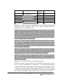
2 Pixie API
The Pixie API consists of a set of C functions for building various coincidence data acquisition
applications. It can be used to configure Pixie modules, make MCA or list mode runs and
retrieve data from the Pixie modules. The API can be compiled as a WaveMetrics Igor XOP file
which is currently used by the Pixie Viewer, a dynamic link library (DLL), or a static library to
1
Pixie-4 Programmer’s Manual V3.11
XIA 2014. All rights reserved.
be used in customized user interfaces or applications. It can also be compiled for Linux and a
sample ROOT interface is available from XIA. In order to better illustrate the usage of these
functions, an overview of the Pixie operation is given below and the usage of these functions is
described in the following.
At first the Pixie API needs to be initialized. This is a process in which the names of system
configuration files and variables are downloaded to the API.
The function
Pixie_Hand_Down_Names is used to achieve this.
The second step is to boot the Pixie modules. It involves initializing each PXI(e) slot where a
Pixie module is installed, downloading all FPGA configurations and booting the digital signal
processor (DSP). It concludes with downloading all DSP parameters (the instrument settings)
and commanding the DSP to program the FPGAs and the on-board digital to analog converters
(DACs). All this has been encapsulated in a single function Pixie_Boot_System.
Now, the instrument is ready for data acquisition. The function used for this purpose is
Pixie_Acquire_Data. By setting different run types, it can be used to start, stop or poll a data
acquisition run (list mode run, MCA run, or special task runs like acquiring ADC traces). It can
also be used to retrieve list mode or histogram data from the Pixie modules.
After checking the quality of a MCA spectrum, a Pixie user may decide to change one or more
settings like energy filter rise time or flat top. The function used to change Pixie settings is
Pixie_User_Par_IO. This function converts a user parameter like energy filter rise time in μs
into a number understood by the Pixie hardware or vice versa.
Pixie_Get_Par_Idx and Pixie_Get_Par_Name are the two functions employed to assist in
using Pixie_User_Par_IO when the Pixie-500e C library is linked dynamically to the user's
application (.dll library). In this case the names of the user-controlled variables and their indexes
in arrays are not accessible to the user's application. The user, therefore, is lead to inquire the
library regarding a particular parameter of interest either through an index or a string.
Another function, Pixie_Buffer_IO, is used to read data from DSP’s internal memory to the host
or write data from the host into the internal memory. This is useful for diagnosing Pixie modules
by looking at their internal memory values. The other usage of this function is to read, save,
copy or extract Pixie’s configurations though its settings files.
In a multi-module Pixie-4 system, it is essential for the host to know which module or channel it
is communicating to. The function Pixie_Set_Current_ModChan is used to set the current
module and channel. The detailed description of each function is given below.
2
Pixie-4 Programmer’s Manual V3.11
XIA 2014. All rights reserved.
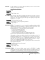
Pixie_Hand_Down_Names
Syntax
S32 Pixie_Hand_Down_Names (
U8 *Names[],
// An array containing the names to be downloaded
U8 *Name);
// A string indicating the type of names (file or
// variable names) to be downloaded
Description
Use this function to download the file or variable names from the host user interface to the Pixie
API. The API needs these file names so that it can read the Pixie hardware configurations from
the files stored in the host computer and download these configurations to the Pixie. The
variable names are used by the API to obtain the indices of the DSP variables when the API
converts user variable values into DSP variable values or vice versa.
Note: Since variable names are now defined in the C library itself, this function is only required
for the Igor and LabView host interfaces. Other, C based interfaces usually do not require it, see
the sample programs for examples on how to specify the file names in the library array
“Boot_File_Name_List”.
Parameter description
Names is a two dimensional string array containing either the file names or the variable names.
The API will know which type of names is being downloaded by checking the other parameter
Name:
1. ALL_FILES: This indicates we are downloading boot files names. In this case, Names
is a string array which has N_BOOT_FILES elements. Currently N_BOOT_FILES is
defined as 16. The elements of Names are the names of FPGA files, DSP executable
code binary file, DSP I/O parameter values file, DSP code I/O variable names file, and
DSP code memory variable names file. All file names should contain the complete path
name.
2. SYSTEM: This indicates we are downloading System_Parameter_Names.
System_Parameter_Names are those global variables that are applicable to all modules in
a Pixie system, e.g. number of Pixie modules in the chassis, etc.
System_Parameter_Names currently can hold 64 names. If less than 64 names are
needed (which is the current case), the remaining names should be defined as empty
strings.
3. MODULE: This indicates we are downloading Module_Parameter_Names.
Module_Parameter_Names are those global variables that are applicable to each
individual module, e.g. module number, module CSR, coincidence pattern, and run type,
etc. Module_Parameter_Names can currently hold 64 names. If less than 64 names are
3
Pixie-4 Programmer’s Manual V3.11
XIA 2014. All rights reserved.
needed (which is the current case), the remaining names should be defined as empty
strings.
4. CHANNEL: This indicates we are downloading Channel_Parameter_Names.
Channel_Parameter_Names are those global variables that are applicable to individual
channels of the Pixie modules, e.g. channel CSR, filter rise time, filter flat top, voltage
gain, and DC offset, etc. Channel_Parameter_Names currently can hold 64 names. If less
than 64 names are needed (which is the current case), the remaining names should be
defined as empty strings.
A detailed description of System/Module/Channel_Parameter_Names is given in Table 3.5.
Return values
Value Description Error Handling
0
-1
Success
Invalid name
None
Check the second parameter
Name
Usage example
S32 retval;
// download system parameter names; define System_Parameter_Names first
retval = Pixie_Hand_Down_Names(System_Parameter_Names, "SYSTEM");
if(retval < 0)
{
// error handling
}
// download module parameter names; define Module_Parameter_Names first
retval = Pixie_Hand_Down_Names(Module_Parameter_Names, "MODULE");
if(retval < 0)
{
// error handling
}
// download channel parameter names; define Channel_Parameter_Names
// first
retval = Pixie_Hand_Down_Names(Channel_Parameter_Names, "CHANNEL");
if(retval < 0)
{
// error handling
}
// download boot file names; define All_Files first
retval = Pixie_Hand_Down_Names(All_Files, "ALL_FILES");
if(retval < 0)
{
// error handling
}
4
Pixie-4 Programmer’s Manual V3.11
XIA 2014. All rights reserved.
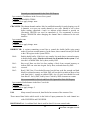
Pixie_Boot_System
Syntax
S32 Pixie_Boot_System (
U16 Boot_Pattern); // The Pixie-4 boot pattern
Description
Use this function to boot all Pixie modules in the system. Before booting the modules, it scans
all PXI(e) crate slots and finds the address for each slot where a Pixie module is installed.
Parameter description
Boot_Pattern is a bit mask used to control the boot pattern of Pixie modules:
Bit 0: Boot communication FPGA
Bit 1: Boot signal processing FPGA
Bit 2: Boot DSP
Bit 3: Load DSP parameters
Bit 4: Apply DSP parameters (call Set_DACs and Program_FIPPI)
Under most of the circumstances, all the above tasks should be executed to initialize the Pixie
modules, i.e. the Boot_Pattern should be 0x1F. Programs executing only a subset of fucntions,
for example starting a list mode run after the Pixie modules have been booted by another
program, may have to use Boot_Pattern 0x0 to initialize the communication (without rebooting
the modules).
Return values
Value Description
Error Handling
0
-1
-2
None
Check PXI slot map
Check comFPGA file
-3
-4
-5
-6
-7
-8
Success
Unable to scan crate slots
Unable to read communication FPGA configuration (Rev.
B)
Unable to read communication FPGA configuration (Rev.
C)
Unable to read signal processing FPGA configuration
Unable to read DSP executable code
Unable to read DSP parameter values
Unable to initialize DSP parameter names
Failed to boot all modules present in the system
Check comFPGA file
Check SPFPGA file
Check DSP code file
Check DSP parameter file
Check DSP .var file
Check Pixie modules
Usage example
S32 intval;
retval = Pixie_Boot_System(0x1F);
5
Pixie-4 Programmer’s Manual V3.11
XIA 2014. All rights reserved.
if(ret < 0)
{
// error handling
}
6
Pixie-4 Programmer’s Manual V3.11
XIA 2014. All rights reserved.
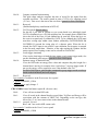
Pixie_User_Par_IO
Syntax
S32 Pixie_User_Par_IO (
double *User_Par_Values,
U8 *User_Par_Name,
U8 *User_Par_Type,
U16 Direction,
U8 ModNum,
U8 ChaNum);
//
//
//
//
//
//
//
//
//
A double precision array containing
the user parameters to be transferred
A string variable indicating which user
parameter is being transferred
A string variable indicating which type
of user parameters is being transferred
I/O direction (read or write)
Number of the module to work on
Channel number of the Pixie module
Description
Use this function to transfer user parameters between the user interface, the API and DSP’s I/O
memory. Some of these parameters ( User_Par_Type = “SYSTEM”) are applicable to all Pixie
modules in the system, like the total number of Pixie modules in the system. Other parameters
(User_Par_Type = “MODULE”) are applicable to a whole Pixie module (independent of its four
channels), e.g. coincidence pattern, Module CSRA, etc. The final set of parameters
(User_Par_Type = “CHANNEL”) are applicable to each individual channel in a Pixie module,
e.g. energy filter settings or voltage gain, etc. For those parameters which need to be transferred
to or from DSP’s internal memory (other parameters such as number of modules are only used
by the API), this function will call another function UA_PAR_IO which first converts these
parameters into numbers that are recognized by both the DSP and the API then performs the
transfer.
Parameter description
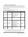
User_Par_Values is a double precision array containing the parameters to be transferred.
Depending on another input parameter User_Par_Type, different User_Par_Values array should
be used. Totally three User_Par_Values arrays should be defined and all of them are onedimensional arrays. The corresponding relationship between User_Par_Values and
User_Par_Type is shown in Table 2.1.
Table 2.1: The Combination of User_Par_Name and User_Par_Values.
User_Par_Type
SYSTEM
MODULE
CHANNEL
User_Par_Values
Name
System_Parameter_Values
Module_Parameter_Values
Channel_Parameter_Values
Size
64
6417
64174
Data Type
Double precision
Double precision
Double precision
The way to fill the Channel_Parameter_Values array is to fill the channel first then the module.
For instance, first 64 values are stored in the array for channel 0, and then repeat this for other
7
Pixie-4 Programmer’s Manual V3.11
XIA 2014. All rights reserved.
three channels. After that, 644 values have been filled for module 0. Then repeat this for the
remaining modules. For the Module_Parameter_Values array, first store 64 values for module 0,
and then repeat this for the other modules.
User_Par_Name is the name of the variable which is to be transferred. It is one element of one
of the arrays System/Module/Channel_Parameter_Names listed in Table 3.5. In addition, the
following keywords are recognized:
Key Word
Action
ALL_SYSTEM_PARAMETERS
ALL_MODULE_PARAMETERS
(read only) read all system parameters
(read only) read all module parameters of a module,
except RUN_TYPE
MODULE_RUN_STATISTICS
(read only) read all module run statistics parameters
of a module
ALL_CHANNEL_PARAMETERS
(read only) read all channel parameters of a channel
CHANNEL_RUN_STATISTICS
(read only) read all channel run statistics parameters
of the 4 channel in a module
Note: The key words “UPDATE_FILTERRANGE_PARAMS” and “FIND_TAU” are obsolete.
The former action is performed automatically after changing FILTERRANGE. The latter is now
a control task.
direction indicates the transfer direction of parameters:
0 - download (write) parameters from the user interface to the API;
1 - upload (read) parameters from the API to the user interface.
ModNum is the number of the Pixie module being communicated to.
ChanNum is the channel number of the Pixie module being communicated to.
Return values
Value Description
Error Handling
0
-1
-2
-3
-4
-5
-6
None
Check User_Par_Values
Check User_Par_Name
Check User_Par_Type
Check direction
Check ModNum
Check ChanNum
Success
Null pointer for User_Par_Values
Invalid user parameter name
Invalid user parameter type
Invalid I/O direction
Invalid Pixie module number
Invalid Pixie channel number
8
Pixie-4 Programmer’s Manual V3.11
XIA 2014. All rights reserved.
Usage example
U16 direction, modnum, channum;
S32 retval;
direction = 0;
modnum = 0;
channum = 1;
// download
// Module #0
// Channel #1
// set module parameter COINCIDENCE_PATTERN to 0xFFFF
Module_Parameter_Values[Coincidence_Pattern_Index]=0xFFFF;
// download COINCIDENCE_PATTERN to the DSP
retval = Pixie_User_Par_IO(Module_Parameter_Values,
"COINCIDENCE_PATTERN", “MODULE”, direction, modnum, channum);
if(retval < 0)
{
// error handling
}
// set channel parameter ENERGY_RISETIME to 6.0 μs
Channel_Parameter_Values[ENERGY_RISETIME_Index]=6.0;
// download ENERGY_RISETIME to DSP
retval = Pixie_User_Par_IO(Channel_Parameter_Values, “ENERGY_RISETIME”,
“CHANNEL”, direction, modnum, channum);
if(retval < 0)
{
// error handling
}
9
Pixie-4 Programmer’s Manual V3.11
XIA 2014. All rights reserved.
Pixie_Get_Par_Name
Syntax
S32 Pixie_Get_Par_Name (
U16 Idx,
U8 *User_Par_Type,
U8 *User_Par_Name);
//
//
//
//
//
//
Parameter index in the array of parameter
names
A string variable indicating which type
of user parameters is being requested
The pointer to a string array to contain
the variable name being requested
Description
Use this function to identify user parameters by type ( “SYSTEM”, “MODULE”, “CHANNEL”) and
index in the type-associated list. The typical use of this function is to check whether a particular
variable exists in the list, or to create a local copy of the entire list.
Parameter description
is an unsigned short variable indicating the sequential number of a user-controlled parameter
in the list of SYSTEM, MODULE or CHANNEL type parameters.
Idx
User_Par_Type is a string describing the type of the parameter in consideration: ''SYSTEM'',
''MODULE'' or ''CHANNEL''.
User_Par_Name is a character array of at least size 80 to contain the name of the requested
parameter.
Return values
Value Description
Error Handling
0
-1
-2
-3
-4
-5
None
Check if Idx exceeds 63
Check if Idx exceeds 63
Check if Idx exceeds 63
Check if ''SYSTEM'', ''MODULE'' or ''CHANNEL''
Check if User_Par_Name is allocated
Success
Invalid system parameter index
Invalid module parameter index
Invalid channel parameter index
Invalid parameter type
NULL parameter name array ptr
10
Pixie-4 Programmer’s Manual V3.11
XIA 2014. All rights reserved.
Usage example
// Check if parameter exists
U8 *ParName = NULL;
U16 i = 0;
ParName = malloc(80 * sizeof(char));
if (!ParName) {
//Not enough memory error handling
}
while(Pixie_Get_Par_Name(i,“MODULE”, ParName) != -1) {
if(!strcmp(ParName, “FILTER_RANGE”)) {
printf(“FILTER_RANGE exists\n”);
break;
}
i++;
}
if(i > 63) {
//error handling
}
11
Pixie-4 Programmer’s Manual V3.11
XIA 2014. All rights reserved.
Pixie_Get_Par_Idx
Syntax
S16 Pixie_Get_Par_Idx (
U8 *User_Par_Name,
U8 *User_Par_Type);
//
//
//
//
A string variable indicating
the variable name being requested
A string variable indicating which type
of user parameters is being requested
Description
Use this function to identify parameter index by type ( “SYSTEM”, “MODULE”, “CHANNEL”) in
the type-associated list. The typical use of this function is to determine the index in
User_Par_Values of Pixie_User_Par_IO to transfer parameter values to and from the device.
Parameter description
User_Par_Type is a string describing the type of the parameter in consideration: ''SYSTEM'',
''MODULE'' or ''CHANNEL''.
User_Par_Name is the name of the variable for which the index is being requested.
Return values
Value Description
Error Handling
Idx
-1
-2
-3
-4
None
Check if ''SYSTEM'', ''MODULE'' or ''CHANNEL''
Check spelling
Check spelling
Check spelling
Success
Invalid parameter type
Invalid system parameter name
Invalid module parameter name
Invalid channel parameter name
12
Pixie-4 Programmer’s Manual V3.11
XIA 2014. All rights reserved.
Usage example
// Write to module
SysParValues[Pixie_Get_Par_Idx("NUMBER_MODULES",
"SYSTEM")] = 1;
SysParValues[Pixie_Get_Par_Idx("OFFLINE_ANALYSIS", "SYSTEM")] = 1;
SysParValues[Pixie_Get_Par_Idx("AUTO_PROCESSLMDATA", "SYSTEM")] = 0;
SysParValues[Pixie_Get_Par_Idx("MAX_NUMBER_MODULES", "SYSTEM")] = 7;
SysParValues[Pixie_Get_Par_Idx("KEEP_CW",
"SYSTEM")] = 1;
Pixie_User_Par_IO(SysParValues,"NUMBER_MODULES", "SYSTEM", MOD_WRITE, 0, 0);
Pixie_User_Par_IO(SysParValues,"OFFLINE_ANALYSIS","SYSTEM", MOD_WRITE, 0, 0);
Pixie_User_Par_IO(SysParValues,"AUTO_PROCESSLMDATA","SYSTEM",MOD_WRITE, 0,0);
Pixie_User_Par_IO(SysParValues,"MAX_NUMBER_MODULES","SYSTEM",MOD_WRITE,0, 0);
Pixie_User_Par_IO(SysParValues,"KEEP_CW",
"SYSTEM", MOD_WRITE, 0, 0);
13
Pixie-4 Programmer’s Manual V3.11
XIA 2014. All rights reserved.
Pixie_Acquire_Data
Syntax
S32 Pixie_Acquire_Data
U16 Run_Type,
//
U32 *User_data,
//
//
U8 *file_name,
//
//
U8 ModNum);
//
(
Data acquisition run type
An unsigned 32-bit integer array containing the
data to be transferred
Name of the file used to store list mode or MCA
histogram data
The number of the Pixie module
Description
Use this function to acquire ADC traces, MCA histogram, or list mode data. The string variable
file_name should always be specified – for start/stop poll of acquisition runs it is the filename for
the data, in other cases it is the filename to be processed. In rare cases, file_name can be
specified as an empty string. The unsigned 32-bit integer array User_data is only used for
acquiring ADC traces (control task 0x84), reading out list mode data or MCA spectra. In all
other cases, User_data can be any unsigned integer array with arbitrary size. Make sure that
User_data has the correct size and data type before reading out ADC traces, list mode data, or
MCA spectrum.
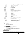
Parameter description
Run_Type is a 16-bit word whose lower 12-bit specifies the type of either data run or control task
run and upper 4-bit specifies actions (start\stop\poll) as described below. Controltasks are
described in detail in section 4.5.
Lower 12-bit:
0x100,0x101,0x102,0x103
0x400,0x201,0x202,0x203
0x301
0x1 -> 0x7F
0x80 -> 0xFF
Upper 4-bit:
0x0000
0x0000
0x0001
0x0002
0x0005
0x0006
0x0016
1
list mode runs (Pixie-4 and Pixie-500)
list mode runs (Pixie-500 Express)
MCA run
control task runs handled by DSP
control task runs handled by C library
start a control task run
set offset DACs1
connect inputs (Pixie-4 only)
disconnect inputs (Pixie-4 only)
program Fippi FPGA1
measure baselines
test writing to external list mode memory
Should be called after most parameter changes applied directly to the DSP (using Pixie_Buffer_IO). Automatically
called after parameter changes handled by the C library (using Pixie_User_Par_IO).
Pixie-4 Programmer’s Manual V3.11
14
XIA 2014. All rights reserved.
0x001A
0x0080
0x0081
0x0083
0x0084
0x1000
0x2000
0x3000
0x4000
0x5000
0x6000
0x7000
0x7001
0x7002
0x7003
0x7004
0x7005
0x7006
0x7007
0x7008
0x7010
0x8000
0x9000
0x9001
0x9002
0x9003
0x9004
test writing to external histogram memory
measure baselines and compute BLcut for all modules
find values of for all modules
adjust offsets2
collect ADC traces2
start a new data run
resume a data run
stop a data run
poll run status
read histogram data and save it to a file
read list mode buffer data and save it to a file
offline list mode data parse routines
parse list mode data file
locate traces
read traces
read energies
read PSA values
read extended PSA values
locate events
read event
custom parsing with user defined functions
manually read MCA histogram from a MCA file
external memory (EM) I/O
read histogram memory section of EM
write to histogram memory section of EM
read list mode memory section of EM
write to list mode memory section of EM
User_data has the following format for the run types listed below:
0x84:
Get ADC traces
Length must be ADCTraceLen*NumberOfChannels, i.e. 8192 * 4 = 32K.
All array elements are return values.
the Nth 8K of data are the ADC trace of channel N.
0x7001: Parse list mode data file
Length must be 2* PRESET_MAX_MODULES, i.e. 34
All array elements are return values.
User_data[i] = NumEvents of module i
User_data[i+PRESET_MAX_MODULES] = TotalTraces of module i
0x7002: Locate Traces of all events
Length must be (TotalTraces of ModNum)*3*NumberOfChannels
2
Combined action of DSP and C library. DSP will perform the controltask 3 or 4 described in section 4.5 and C
library will use the results. For backwards compatibility, RunType 0x0003 or 0x0004 are translated into 0x0083 or
0x0084, respectively in the C library.
Pixie-4 Programmer’s Manual V3.11
15
XIA 2014. All rights reserved.
All array elements are return values.
User_data[i*3n] = Location of channel n’s trace in file for event i (word number)
User_data[i*3n+1] = length of channel n’s trace
User_data[i*3n+2] = energy for channel n
0x7003: Read Traces of one event
Length must be (NumberOfChannels*2+combined tracelength of channels)
First (NumberOfChannels*2) elements are input values:
User_data[2n] = Location of channel n’s data in file for selected event (word number)
User_data[2n+1] = length of channel n’s trace
The remaining array elements are return values.
User_data[8 …] = Trace data of channel 0 followed by channels 1,2, and 3.
0x7004: Read Energies of all events
Length must be (NumEvents of ModNum * NumberOfChannels )
All array elements are return values.
User_data[i*4+n] = energy of channel n for event i
0x7005: Read PSA values of all events
Length must be (NumEvents of ModNum*2 * NumberOfChannels )
All array elements are return values.
User_data[i*2n] = XIAPSA word of channel n for event i
User_data[i*2n+1] = UserPSA word of channel n for event i
0x7006: Read extended PSA values of all events
Length must be (NumEvents of ModNum*8 * NumberOfChannels )
All array elements are return values.
User_data[i*8n] = Channel Header 0 or 4/5 (usually timestamp) of channel n for event i
16 bit for Pixie-4 and Pixie-500, 32 bit for Pixie-500e
User_data[i*8n+1] = Channel Header 1 or 8 ( energy ) of channel n for event i
User_data[i*8n+2] = Channel Header 2 or 11 ( XIAPSA) of channel n for event i
User_data[i*8n+3] = Channel Header 3 or 10 (UserPSA) of channel n for event i
User_data[i*8n+4] = Channel Header 4 or 12 (ExtendedPSA1) of channel n for event i
User_data[i*8n+5] = Channel Header 5 or 13 (ExtendedPSA2) of channel n for event i
User_data[i*8n+6] = Channel Header 6 or 14 (ExtendedPSA3) of channel n for event i
User_data[i*8n+7] = Channel Header 7 or 15 (RealTime High or ExtendedPSA4)
of channel n for event i
Notes: Headers 1-7 can be modified by DSP user routine in customized code.
In Pixie-4 and Pixie-500 standard DSP code, Header 7 contains RealTime High word
0x7007: Locate all events
Length must be (NumEvents of ModNum)*3
All array elements are return values.
User_data[i*3] = Location of event i in file (word number)
User_data[i*3+1] = Location of buffer header start for event i in file
User_data[i*3+2] = Length of event i (event header, channel header, traces)
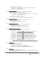
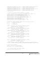
0x7008: Read one event
Length must be (length of selected event) + 7 +36
(this is longer than actually used, but ensures enough room for channel headers in all runtypes)
First 3 elements are input values:
16
Pixie-4 Programmer’s Manual V3.11
XIA 2014. All rights reserved.
User_data[0] = Location of selected event in file (word number)
User_data[1] = Location of buffer header start for selected event in file
User_data[2] = Length of selected event
The remaining array elements are return values.
User_data[3 …6] are the tracelengths of channel 0-3
User_data[7 …6+BHL] contain the buffer header corresponding to the selected event
User_data[7+BHL .. 6+BHL+EHL] contain the event header
User_data[7+BHL+ELH .. 6+BHL+EHL+4*CHL] are the channel headers for
channel 0-3; always 9 words per channel header, but in compressed runtypes
some entries are be invalid
User_data[7+BHL+EHL+4*CHL …] contain the traces of channel 0-3,
followed by some undefined values (use tracelength to parse traces)
Summary of User_data array in run task 0x7008
Location P4
P500e
Header Header
Value
Pixie-500e or Pixie-4
0
Location of event
1
Location of event
2
Length of event
3
TL0
4
TL1
5
TL2
6
TL3
7
BH0
8
BH1
FH1
Module number
9
BH2
FH2
Run type (data format
indicator): 0x100-0x403
10
BH3
CH6
TrigTimeHI or
Notes
P500e: unused
Unused or BUF_NDATA
High 16 bits of Trigger or Buffer time
BUF_TIMEHI
11
BH4
CH5
TrigTimeMI or
Middle 16 bits of Trigger or Buffer time
BUF_TIMEMI
12
BH5
CH4
TrigTimeLO or
Lower 16 bits of Trigger or Buffer time
BUF_TIMELO
13
EH0
CH1,0
EvtPattern and EvtInfo
or EVT_PATTERN
32 or 16 bit event info and hit pattern
14
EH1
CH5
TrigTimeMI or
Middle 16 bits of Trigger or Event time
EVT_TIMEMI
15
EH2
CH4
TrigTimeLO or
Lower 16 bits of Trigger or Event time
EVT_TIMELO
16
CH0
17
CH1
CH5,4
Unused or
CHAN_NDATA
Channel data length
TrigTimeMI and
TrigTimeLO or
Lower 16 bits and middle 16 bits of Trigger
time or (all) 16 bits of Channel time
CHAN_TRIGTIME
17
Pixie-4 Programmer’s Manual V3.11
XIA 2014. All rights reserved.
18
CH2
CH8
CHAN_ENERGY
energy
19
CH3
CH11
CHAN_XIAPSA
XIA PSA value (or user return)
20
CH4
CH10
CHAN_USERPSA
USER PSA value (or user return)
21
CH5
CH12
Unused
(user return)
22
CH6
CH13
Unused
(user return)
23
CH7
CH14
Unused
(user return)
24
CH8
CH15
Unused or TIME HI
Channel header repeated 4 times. Followed by waveforms
(user return) or High 16 bits of time
0x8000: Read MCA data from file (one module)
Length must be HISTOGRAM_MEMORY_LENGTH = 131072
0x9001: Read MCA data from one module
Length must be HISTOGRAM_MEMORY_LENGTH = 131072
0x9002: Write MCA data to one module (debug)
Length must be HISTOGRAM_MEMORY_LENGTH = 131072
0x9003: Read List mode data in external memory from one module
Length must be LIST_MEMORY_LENGTH = 131072
0x9004: Write List mode data to external memory one module (debug)
Length must be LIST_MEMORY_LENGTH = 131072
file_name is a string variable which specifies the name of the output file. It needs to have the
complete file path.
ModNum is the number of the module addressed, counting from 0 to (number of modules - 1). If
ModNum == (number of modules), all modules are addressed in a for loop, however this option
is not valid for all RunTypes.
Return values
Return values depend on the run type:
Run type = 0x0000
Value Description
Error Handling
0
-0x1
-0x2
-0x3
-0x4
None
Check ModNum
Reboot the module
Reboot the module
Reboot the module
Success
Invalid Pixie module number
Failure to adjust offsets
Failure to acquire ADC traces
Failure to start the control task run
18
Pixie-4 Programmer’s Manual V3.11
XIA 2014. All rights reserved.
Run type = 0x1000
Value Description
0x10
-0x11
-0x12
Error Handling
Success
None
Invalid Pixie module number Check ModNum
Reboot the module
Failure to start the data run
Run type = 0x2000
Value Description
Error Handling
0x20
-0x21
-0x22
None
Success
Invalid Pixie module number Check ModNum
Failure to resume the data run Reboot the module
Run type = 0x3000
Value Description
0x30
-0x31
-0x32
Error Handling
Success
None
Invalid Pixie module number Check ModNum
Reboot the module
Failure to end the run
Run type = 0x4000
Value
Description
0
1
CSR value
-0x41
No run is in progress
Run is in progress
Error Handling
N/A
N/A
N/A
When run type = 0x40FF
Invalid Pixie module number Check ModNum
Run type = 0x5000
Value Description
Error Handling
0x50
-0x51
None
Check the file name
Success
Failure to save histogram data to a
file
Run type = 0x6000
Value Description
Error Handling
0x60
-0x61
None
Check the file name
Success
Failure to save list mode data to a
file
Run type = 0x7000
Value Description
Error Handling
0x70
None
Success
19
Pixie-4 Programmer’s Manual V3.11
XIA 2014. All rights reserved.
-0x71
-0x72
-0x73
-0x74
-0x75
-0x76
-0x77
-0x78
-0x79
Failure to parse the list mode data file
Failure to locate list mode traces
Failure to read list mode traces
Failure to read event energies
Failure to read PSA values
Failure to read extended PSA values
Failure to locate events
Failure to read events
Invalid list mode parse analysis request
Check list mode data file
Check list mode data file
Check list mode data file
Check list mode data file
Check list mode data file
Check list mode data file
Check list mode data file
Check list mode data file
Check run type
Run type = 0x8000
Value Description
Error Handling
0x80
-0x81
None
Success
Failure to read out MCA spectrum from the file Check the MCA data file
Run type = 0x9000
Value Description
Error Handling
0x90
-0x91
-0x92
-0x93
-0x94
-0x95
None
Reboot the module
Reboot the module
Reboot the module
Reboot the module
Check the run type
Success
Failure to read out MCA section of external memory
Failure to write to MCA section of external memory
Failure to read out LM section of external memory
Failure to write to LM section of external memory
Invalid external memory I/O request
Usage example
S32 retval;
U16 RunType;
U32 dummy[2];
U8 ModNum;
RunType = 0x1100;
// start a new list mode run
ModNum = 0;
retval = Pixie_Acquire_Data(RunType, dummy, “ ”, ModNum);
if(retval != 0x10)
{
// Error handling
}
// wait until the run has ended
RunType = 0x4100;
while( ! Pixie_Acquire_Data(RunType, dummy, “ ”, ModNum) ) {;}
// Read out the list mode data from all Pixie modules and save to a file
RunType = 0x6100;
20
Pixie-4 Programmer’s Manual V3.11
XIA 2014. All rights reserved.
retval = Pixie_Acquire_Data(RunType, dummy,
“C:\XIA\Pixie4\PulseShape\Listdata0001.bin”, ModNum);
if(retval != 0x60)
{
// Error handling
}
// Read out the histogram data from all Pixie modules and save to a file
RunType = 0x5100;
retval = Pixie_Acquire_Data(RunType, dummy,
“C:\XIA\Pixie4\MCA\Histdata0001.bin”, ModNum);
if(retval != 0x50)
{
// Error handling
}
21
Pixie-4 Programmer’s Manual V3.11
XIA 2014. All rights reserved.
Pixie_Set_Current_ModChan
Syntax
S32 Pixie_Set_Current_ModChan (
U8 Module,
// Module number to be set
U8 Channel);
// Channel number to be set
Description
Use this function to set the current module number and channel number.
Parameter description
Module specifies the current module to be set. Module should be in the range of 0 to
NUMBER_MODULES in the System_Parameter_Values. (Currently the overall maximum as
defined by PRESET_MAX_MODULES is 17).
Channel specifies the current channel to be set. Channel should be in the range of 0 to
NUMBER_OF_CHANNELS - 1 (currently NUMBER_OF_CHANNELS is set to 4).
Return values
Value Description
Error Handling
0
-1
-2
None
Check Module
Check Channel
Success
Invalid module number
Invalid channel number
Usage example
// Set current module to 1 and current channel to 3
Pixie_Set_Current_ModChan(1, 3);
22
Pixie-4 Programmer’s Manual V3.11
XIA 2014. All rights reserved.
Pixie_Buffer_IO
Syntax
S32 Pixie_Buffer_IO (
U16 *Values,
// An unsigned 16-bit integer array containing the
// data to be transferred
U8 type,
// Data transfer type
U8 direction,
// Data transfer direction
U8 *file_name, // File name
U8 ModNum);
// Module number
Description
Use this function to:
1) Download or upload DSP parameters between the user interface and the Pixie modules;
2) Save DSP parameters into a settings file or load DSP parameters from a settings file and
applies to all modules present in the system;
3) Copy parameters from one module to others or extracts parameters from a settings file
and applies to the selected modules.
Parameter description
Values is an unsigned 16-bit integer array used for data transfer between the user interface and
Pixie modules. type specifies the I/O type. direction indicates the data flow direction. The
string variable file_name contains the name of settings files. Different combinations of the three
parameters - Values, type, direction – designate different I/O operations as listed in Table 2.2.
Table 2.2: Different I/O operations using function Pixie_Buffer_IO.
Type
0
1
2
Direction
0
1
0*
1
0
1
0
3
1
Values
DSP I/O variable values
Values to be written
All DSP variable values
N/A**
Values[0] – source module
number; Values[1] – source
channel number; Values[2] –
copy/extract pattern bit mask;
Values[3], Values[4], … destination channel pattern
23
I/O Operation
Write DSP I/O variable values to modules
Read DSP I/O variable values from modules
Write to certain locations of the data memory
Read all DSP variable values from modules
Save current settings in all modules to a file
Read settings from a file and apply to all
modules in the system
Extract settings from a file and apply to
selected modules
Copy settings from a source module to
destination modules
Pixie-4 Programmer’s Manual V3.11
XIA 2014. All rights reserved.
4
N/A***
Values[0] – address; Values[1] –
length
Specify the location and number of words to be
written into the data memory
Notes:
*
Special care should be taken for this I/O operation since mistakenly writing to some locations of the data
memory will cause the system to crash. The Type 4 I/O operation should be called first to specify the
location and the number of words to be written before calling this one. If necessary, please contact XIA
for assistance.
**
Any unsigned 16-bit integer array could be used here.
***
Direction can be either 0 or 1 and it has no effect on the operation.
Return values
Value Description
0
-1
-2
-3
-4
-5
-6
-7
-8
-9
-10
-11
-12
Error Handling
Success
None
Reboot the module
Failure to set DACs after writing DSP parameters
Reboot the module
Failure to program Fippi after writing DSP parameters
Reboot the module
Failure to set DACs after loading DSP parameters
Reboot the module
Failure to program Fippi after loading DSP parameters
Check the file name
Can't open settings file for loading
Check the file name
Can't open settings file for reading
Check the file name
Can't open settings file to extract settings
Reboot the module
Failure to set DACs after copying or extracting settings
Failure to program Fippi after copying or extracting settings Reboot the module
Check ModNum
Invalid module number
Check direction
Invalid I/O direction
Check type
Invalid I/O type
Usage example
S32 retval;
U8 type, direction, modnum;
modnum = 0;
// Module number
// Download DSP parameters to the current Pixie module; DSP_Values is
a
// pointer pointing to the DSP parameters; no need to specify file name
// here.
direction = 0;
// Write
type = 0;
// DSP I/O values
retval = Pixie_Buffer_IO(DSP_Values, type, direction, “”, modnum);
if(retval < 0)
{
// Error handling
}
// Read DSP memory values from the current Pixie module; Memory_Values
// is a pointer pointing to the memory block; no need to specify file
// name Here.
24
Pixie-4 Programmer’s Manual V3.11
XIA 2014. All rights reserved.
direction = 1;
// Read
type = 1;
// DSP memory values
retval = Pixie_Buffer_IO(Memory_Values, type, direction, “”, modnum);
if(retval < 0)
{
// Error handling
}
25
Pixie-4 Programmer’s Manual V3.11
XIA 2014. All rights reserved.
Options for Compiling Pixie API
The Pixie API can be compiled as either a WaveMetrics Igor XOP file used by the Pixie Viewer,
a dynamic link library (DLL) or static library, or can be used by a standalone C program. The
two latter options can be used by advanced users to integrate Pixie modules into their own data
acquisition systems. Sample make files and MS Visual Studio project files (version 2005) are
included in the distribution.
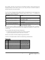
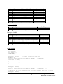
The following table summarizes the required files for these options.
Table 2.3: Options for compiling the Pixie C Driver.
Compilation
Option
C source files
Files required
for all options
Boot.c, eeprom.c,
pixie_c.c, utilities.c,
ua_par_io.c
Additional files
for a dynamic
link library
(DLL) or static
library
pixie4VI_DLL.c
Required Files
C header files
boot.h, defs.h, globals.h, sharedfiles.h,
utilities.h,
PciRegs.h, PciTypes.h, PexApi.h
Plx.h, PLX_sysdep.h, PlxApi.h,
PlxTypes.h, Reg9054.h, PlxIoctl.h,
PlxNetIoctl.h, PlxNetTypes.h
plxdefck.h, plxstat.h
pci_Jungo.h
Library files
PlxApi.lib,
PlxApi650.dll
pixie4_iface.h,
Additional files
for Igor XOP
pixie4_iface.c,
pixie4_igor.c,
PixieWinCustom.rc
Additional files
for standalone
program e.g.
sample.c
sample.c or
equivalent
SystemConfig.c
IgorXOP.h, VCExtraIncludes.h,
XOP.h, XOPResources.h,
XOPStandardHeaders.h,
XOPSupport.h,
XOPStructureAlignmentReset.h,
XOPStructureAlignmentTwoByte.h,
XOPSupportWin,
XOPWinMacSupport.h,
XOPWMWinMacSupport.h,
XOPSupport.lib
IGOR.lib
sample.h or equivalent
There are two compiler switches (options) that have to be set by the makefiles or project files:
• COMPILE_IGOR_XOP, if “defined” enables sections of the code used for compiling
the Igor xop. It must not be defined for compilation of the dll or sample code.
26
Pixie-4 Programmer’s Manual V3.11
XIA 2014. All rights reserved.
• XIA_WINDOZE, if “defined” enables sections of the code used for compiling code
for Windows. XIA_Linux, if “defined” enables sections of the code used for compiling
code for Linus. The two options are exclusive.
The Pixie-4 C library is ANSI C compatible as much as possible, but a number of nonstandard functions are used. These are:
Sleep. Throughout the code, the function Pixie_Sleep is used to wait for a time (in ms). In
utilities.c, this function is implemented using the Microsoft Visual C function Sleep. For
other compilations, e.g. in Linux, this function has to implemented differently.
To compile under Linux, files from the PLX software development kit have to be present.
This SDK is available from PLX (www.plxtech.com) and not distributed by XIA. The Linux
make file expects the complete SDK to be present under …\PixieClib\Linux
27
Pixie-4 Programmer’s Manual V3.11
XIA 2014. All rights reserved.
3 Control Pixie Modules via C program
3.1 Initializing
We describe here how to initialize Pixie modules in a PXI(e) chassis using the functions
described in Section 2. As an example, we assume two Pixie-4 modules – residing in slot #3 and
#4, respectively. Users are also encouraged to read the sample C code shipped with the API.
3.1.1 Initialize Global Variables
As discussed in Section 2, we assume that three global variable arrays have been defined:
System_Parameter_Values, Module_Parameter_Values and Channel_Parameter_Values. For
these three global variable arrays, three corresponding global name arrays are defined:
System_Parameter_Names, Module_Parameter_Names and Channel_Parameter_Names,
respectively. Table 3.5 lists the names contained in each of these name arrays. The API uses
search functions to locate a variable value by name at run time.
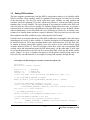
The file names for the DSP and firmware files have to be copied to the internal array
“Boot_File_Name_List” Table 3.2 lists the names and order of files needed to initialize the
Pixie-4 modules.
Table 3.2: File Names in All_Files.
Index
0
1
File Name
Note
2
C:\XIA\Pixie4\Firmware\pixie.bin
3
C:\XIA\Pixie4\DSP\PXIcode.bin
4
5
6
C:\XIA\Pixie4\Configuration\default.set
C:\XIA\Pixie4\DSP\P500e.var
C:\XIA\Pixie4\DSP\PXIcode.lst
7
8
C:\XIA\P500eSW\Firmware\syspixie_RevC.
bin
C:\XIA\P500eSW\Firmware\FippiP500.bin
9
10
C:\XIA\P500eSW\Firmware\pixie500e.bin
C:\XIA\P500eSW\DSP\P500code.bin
11
C:\XIA\P500eSW\DSP\P500e.ldr
12
C:\XIA\P500eSW\DSP\P500e.lst
unused
C:\XIA\Pixie4\Firmware\syspixie_revC.bin
28
Communication FPGA configuration
(Pixie-4 Rev C, D, E)
Signal processing FPGA configuration
(Pixie-4)
DSP executable binary code
for the Pixie-4
Settings file
File of DSP I/O variable names
File of DSP memory variable names
for the Pixie-500 and the Pixie-4
Communication FPGA configuration
(Pixie-500 Rev B)
Signal processing FPGA configuration
(Pixie-500)
FPGA configuration (Pixie-500 Express)
DSP executable binary code for the
Pixie-500
DSP executable binary code for the
Pixie-500 Express
File of DSP memory variable names
for the Pixie-500 Express
Pixie-4 Programmer’s Manual V3.11
XIA 2014. All rights reserved.
The non-read-only variables in the global variable array System_Parameter_Values also need to
be initialized before the API functions are called to start the initialization. Table 3.3 lists those
global variables and the definition of their allowed values.
Table 3.3: Initialization of Module_Global_Values.
Module_Global_Names
Module_Global_
Values
Definition
Default Value
NUMBER_MODULES
2
OFFLINE_ANALYSIS
0
AUTO_PROCESSLMDATA
0
MAX_NUMBER_MODULES
7
KEEP_CW
1
SLOT_WAVE[0]
SLOT_WAVE[1]
SLOT_WAVE[...]
110
111
...
The total number of Pixie-4 modules present
Range: 1.. MAX_NUMBER_MODULES
0 for online analysis,
1 for offline analysis (no I/O with modules)
0 to not writing results in a .dat file while parsing list mode
output data
1 to write standard .dat file during parsing
2 to write extended dt2 file during parsing
Select chassis type
7 = 4,5,6,8-slot chassis
13 = 14-slot XIA 6U chassis
17 = 14,18-slot NI 3U chassis
62 = 8-slot PXI/PXIe NI chassis 1062Q
0 Channel COINC_DELAY is set by user.
1 Channel COINC_DELAY is automatically adjusted to
compensate for difference in energy filter length
Note: not yet implemented for Pixie-500 Express
Module 0 is s/n 110
Module 1 is s/n 111
Module ... is s/n ...
3.1.2 Boot Pixie Modules
The boot procedure for Pixie-4 modules includes the following steps: First, the function
Pixie_User_Par_IO should be called to initialize the global value array
System_Parameter_Values. The, Pixie_Boot_System should be called to boot the modules. The
following code is an example showing how to boot the Pixie-4 modules using the API functions.
An Example Code Illustrating How to Boot Pixie-4 Modules
S32 retval;
U8 d, m, c;
// copy file names into Boot_File_Name_List
strcpy(Boot_File_Name_List[0],"C:\\\...Pixie4\\firmware\\FippiP500.bin\0");
29
Pixie-4 Programmer’s Manual V3.11
XIA 2014. All rights reserved.
strcpy(Boot_File_Name_List[1],"C:\\\...Pixie4\\firmware\\syspixie_RevC.bin\0");
strcpy(Boot_File_Name_List[2],"C:\\\...Pixie4\\firmware\\pixie.bin\0");
strcpy(Boot_File_Name_List[3],"C:\\\...Pixie4\\dsp\\PXIcode.bin\0");
strcpy(Boot_File_Name_List[4],"C:\\\...Pixie4\\configuration\\default.set\0");
strcpy(Boot_File_Name_List[5],"C:\\\...Pixie4\\dsp\\PXIcode.var\0");
strcpy(Boot_File_Name_List[6],"C:\\\...Pixie4\\dsp\\PXIcode.lst\0");
// etc for 7-12
// initialize system parameter VALUES in C program
// Note: indices have to be derived from NAME arrays (table 3.5)
System_Parameter_Values[NUMBER_MODULES_Index] = 2;
System_Parameter_Values[OFFLINE_ANALYSIS_Index] = 0;
System_Parameter_Values[AUTO_PROCESSLMDATA_Index] = 0;
System_Parameter_Values[MAX_NUMBER_MODULES_Index] = 7;
System_Parameter_Values[KEEP_CW]=1;
System_Parameter_Values[SLOT_WAVE_Index] = 110;
System_Parameter_Values[SLOT_WAVE_Index+1] = 111;
// download system parameter VALUES initialized above to API
d = 0;
// direction download
m = 0;
// Module #0
c = 0;
// Channel #0
retval = Pixie_User_Par_IO(System_Parameter_Values,
"NUMBER_MODULES", "SYSTEM", d, m, c);
if( retval < 0 ) // Error handling
retval = Pixie_User_Par_IO(System_Parameter_Values,
"OFFLINE_ANALYSIS", "SYSTEM", d, m, c);
if( retval < 0 ) // Error handling
retval = Pixie_User_Par_IO(System_Parameter_Values,
"AUTO_PROCESSLMDATA", "SYSTEM", d, m, c);
if( retval < 0 ) // Error handling
retval = Pixie_User_Par_IO(System_Parameter_Values,
"MAX_NUMBER_MODULES", "SYSTEM", d, m, c);
if( retval < 0 ) // Error handling
retval = Pixie_User_Par_IO(System_Parameter_Values,
"KEEP_CW", "SYSTEM", d, m, c);
if( retval < 0 ) // Error handling
retval = Pixie_User_Par_IO(System_Parameter_Values,
"SLOT_WAVE", "SYSTEM", d, m, c);
if( retval < 0 ) // Error handling
// Note: System_Parameter_Values contains entries for module 0 and 1
// (slot 3 and 4), the last command (argument “SLOT_WAVE”) applies both
// boot Pixie-4 modules
retval = Pixie_Boot_System(0x1F);
if( retval < 0 ) // Error handling
// set current module and channel number
Pixie_Set_Current_ModChan(0, 0);
30
Pixie-4 Programmer’s Manual V3.11
XIA 2014. All rights reserved.
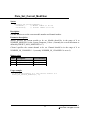
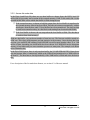
3.2 Setting DSP variables
The host computer communicates with the DSP by setting and reading a set of variables called
DSP I/O variables. These variables, totally 512 unsigned 16-bit integers, sit in the first 512 words
of the data memory. The first 256 words, which store input variables, are both readable and
writeable, while the remaining 256 words, which store pointers to various data buffers and run
summary data, are only readable. The exact location of any particular variable in the DSP code
will vary from one code version to another. To facilitate writing robust user code, we provide a
reference table of variable names and addresses with each DSP code version. Included with the
software distribution is a file called PXIcode.var (or P500code.var, P500e.var). It contains a twocolumn list of variable names and their respective addresses. Thus you can write your code such
that it addresses the DSP variables by name, rather than by fixed location.
It should come as no surprise that many of the DSP variables have meaningful values and ranges
depending on the values of other variables. A complete description of all interdependencies can
be found in Section 4. All of these interdependencies have been taken care of by the Pixie API.
So instead of directly setting DSP variables, users only need to set the values of those global
variables defined in Table 3.5. The API will then convert these values into corresponding DSP
variable values and download them into the DSP data memory. On the other hand, if users want
to read out the data memory, the API will first convert these DSP values into the global variable
values. Tables 3.5a-c give a complete description of all the global variables being used by the
Pixie API. The code shown below is an example of setting DSP variables through the API.
An Example Code Illustrating How to Set DSP Variables through the API
S32 retval;
U8 direction, modnum, channum;
direction = 0; // download
modnum = 0;
// Module #0
channum = 0;
// Channel #0
// Note xxx_Index has to be derived from NAME array (table 3.5)
// set COINCIDENCE_PATTERN to 0xFFFF
Module_Parameter_Values[COINCIDENCE_PATTERN_Index] = 0xFFFF;
// download COINCIDENCE_PATTERN to the DSP
retval = Pixie_User_Par_IO(Module_Parameter_Values,
“COINCIDENCE_PATTERN", "MODULE", direction, modnum, channum);
if( retval < 0 // Error handling
// set ENERGY_RISETIME to 6.0 μs
Channel_Parameter_Values[ENERGY_RISETIME_Index] = 6.0;
// download ENERGY_RISETIME to the DSP
retval = Pixie_User_Par_IO(Channel_Parameter_Values,
“ENERGY_RISETIME", "CHANNEL", direction, modnum, channum);
if( retval < 0 // Error handling
31
Pixie-4 Programmer’s Manual V3.11
XIA 2014. All rights reserved.
Table 3.5a: Descriptions of System Global Variables in Pixie-4.
System_Parameter_Names
NUMBER_MODULES
OFFLINE_ANALYSIS
AUTO_PROCESSLMDATA
C_LIBRARY_RELEASE
C_LIBRARY_BUILD
KEEP_CW
SLOT_WAVE
SLOT_WAVE is followed by up to 16
slot entries. Entries are addressed as
SLOT_WAVE[N]
I/O Type
Read/Write
Read/Write
Read/Write
Read only
Read only
Read/Write
Read/Write
Unit
N/A
N/A
N/A
N/A
N/A
N/A
N/A
Corresponding DSP Variables
N/A
N/A
N/A
N/A
N/A
N/A
N/A
Table 3.5b: Descriptions of Module Global Variables in Pixie-4. Removed variables are crossed out
Module_Parameter_Names
MODULE_NUMBER
MODULE_CSRA
MODULE_CSRB
MODULE_FORMAT
MAX_EVENTS
COINCIDENCE_PATTERN
ACTUAL_COINCIDENCE_WAIT
MIN_COINCIDENCE_WAIT
SYNCH_WAIT
IN_SYNCH
RUN_TYPE
FILTER_RANGE
MODULEPATTERN
NNSHAREPATTERN
DBLBUFCSR
MODULE_CSRC
BUFFER_HEAD_LENGTH
EVENT_HEAD_LENGTH
CHANNEL_HEAD_LENGTH
OUTPUT_BUFFER_LENGTH
NUMBER_EVENTS
RUN_TIME
EVENT_RATE
I/O Type
Read only
Read/Write
Read/Write
Read/Write
Read/Write
Read/Write
Read/Write
Read only
Read/Write
Read/Write
Write only
Read/Write
Read/Write
Read/Write
Read/Write
Read/Write
Read only
Read only
Read only
Read only
Read only
Read only
Read only
Unit
N/A
N/A
N/A
N/A
N/A
N/A
ns
ticks
N/A
N/A
N/A
N/A
N/A
N/A
N/A
N/A
N/A
N/A
N/A
N/A
N/A
s
cps
TOTAL_TIME
BOARD_VERSION
SERIAL_NUMBER
DSP_RELEASE
DSP_BUILD
FIPPI_ID
SYSTEM_ID
XET_DELAY
PDM_MASKA
Read only
Read only
Read only
Read only
Read only
Read only
Read only
Read/Write
Read/Write
s
N/A
N/A
N/A
N/A
N/A
N/A
N/A
N/A
32
Corresponding DSP Variables
MODNUM
MODCSRA
MODCSRB
MODFORMAT
MAXEVENTS
COINCPATTERN
COINCWAIT
COINCWAIT
SYNCHWAIT
INSYNCH
RUNTASK
FILTERRANGE
MODULEPATTERN
NNSHAREPATTERN
DBLBUFCSR
MODCSRC
BUFHEADLEN
EVENTHEADLEN
CHANHEADLEN
LOUTBUFFER
NUMEVENTSX, A, B
RUNTIMEX, A, B, C
NUMEVENTSX, A, B
RUNTIMEX, A, B, C
TOTALTIMEX, A, B, C
<Hardware PROM>
<Hardware PROM>
DSPRELEASE
DSPBUILD
FIPPIID
HARDWAREID
XETDELAY
PDMMASKA
Pixie-4 Programmer’s Manual V3.11
XIA 2014. All rights reserved.
PDM_MASKB
PDM_MASKC
Read/Write
Read/Write
N/A
N/A
PDMMASKB
PDMMASKC
Table 3.5c: Descriptions of Channel Global Variables in Pixie-4.
Channel_Parameter_Names
CHANNEL_CSRA
CHANNEL_CSRB
ENERGY_RISETIME
ENERGY_FLATTOP
TRIGGER_RISETIME
TRIGGER_FLATTOP
TRIGGER_THRESHOLD
VGAIN
VOFFSET
TRACE_LENGTH
TRACE_DELAY
COINC_DELAY
PSA_START
PSA_END
EMIN
BINFACTOR
TAU
BLCUT
XDT
BASELINE_PERCENT
CFD_THRESHOLD
INTEGRATOR
CHANNEL_CSRC
GATE_WINDOW
GATE_DELAY
BLAVG
LIVE_TIME
INPUT_COUNT_RATE
I/O Type
Read/Write
Read/Write
Read/Write
Read/Write
Read/Write
Read/Write
Read/Write
Read/Write
Read/Write
Read/Write
Read/Write
Read/Write
Read/Write
Read/Write
Read/Write
Read/Write
Read/Write
Read/Write
Read/Write
Read/Write
Read/Write
Read/Write
Read/Write
Read/Write
Read/Write
Read/Write
Read only
Read only
Unit
N/A
N/A
μs
μs
μs
μs
N/A
V/V
V
μs
μs
μs
μs
μs
N/A
N/A
μs
N/A
N/A
N/A
N/A
N/A
N/A
μs
μs
N/A
s
cps
FAST_PEAKS
OUTPUT_COUNT_RATE
Read only
Read only
N/A
cps
NOUT
GATE_RATE
Read only
Read only
N/A
cps
GATE_COUNTS
FTDT
SFDT
GDT
CURRENT_ICR
CURRENT_OORF
Read only
Read only
Read only
Read only
Read only
Read only
N/A
s
s
s
cps
%
33
Corresponding DSP Variables
CHANCSRA
CHANCSRB
SLOWLENGTH
SLOWGAP
FASTLENGTH
FASTGAP
FASTTHRESH
GAINDAC
TRACKDAC
TRACELENGTH
USERDELAY
COINCDELAY, RESETDELAY
PSAOFFSET
PSAOFFSET , PSALENGTH
ENERGYLOW
LOG2EBIN
PREAMPTAUA, PREAMPTAUB
BLCUT
XWAIT, XAVG
BASELINEPERCENT
CFDTHR
INTEGRATOR
CHANCSRC
GATEWINDOW
GATEDELAY
LOG2BWEIGHT
LIVETIMEX, A, B, C
FASTPEAKSX, A, B, C
LIVETIMEX, A, B, C,
FTDTX, A, B, C,
FASTPEAKSX, A, B, C
NOUTX,A,B,
LIVETIMEX, A, B, C
NOUTX,A,B,
GCOUNTX, A, B
LIVETIMEX, A, B, C
GCOUNTX,A,B
FTDTX, A. B, C
SFDTX, A, B, C
GDTX, A, B ,C
ICR
OORF
Pixie-4 Programmer’s Manual V3.11
XIA 2014. All rights reserved.
3.3
Access spectrum memory or list mode data
3.3.1 Access spectrum memory
The MCA spectrum memory is fixed to 32K words (32 bits per word) per channel, residing in
the external memory. Therefore, the starting address of the MCA spectrum in the external
memory for Channel #0, 1, 2 and 3 will be 0x00000000, 0x000080000, 0x00010000,
0x00018000, respectively. The reading-out of the spectrum memory to the host is through the
PCI burst read at rates over 100 Mbytes/s. The spectrum memory is accessible even when a data
acquisition run is in progress. The following code is an example of how to start a MCA run and
read out the MCA spectrum after the run is finished.
An Example Code Illustrating How to Access MCA Spectrum Memory
S32 retval;
U8 direction, modnum, channum;
U32 User_Data[131072]; // an array for holding the MCA spectrum data of
// 4 channels
direction = 0;
modnum = 0;
channum = 0;
// download
// Module #0
// Channel #0
// start a MCA run
retval = Pixie_Acquire_Data(0x1301, User_Data, “ ”, modnum);
if( retval < 0 // Error handling
// wait for 30 seconds
Sleep(30000);
// stop the MCA run
retval = Pixie_Acquire_Data(0x3301, User_Data, “ ”, modnum);
if( retval < 0 // Error handling
// save MCA spectrum to a file
retval = Pixie_Acquire_Data(0x5301, User_Data,
“C:\\XIA\\Pixie4\\MCA\Data0001.bin”, modnum);
if( retval < 0 // Error handling
// read out the MCA spectrum and put it to array User_data
retval = Pixie_Acquire_Data(0x9001, User_data, “ ”, modnum);
if( retval < 0 // Error handling
Note that in clover addback mode, the spectrum length is fixed to 16K for each channel plus 16K
of addback spectrum. Therefore, the starting address of the MCA spectrum in the external
memory for Channel #0, 1, 2 and 3 will be 0x00000000, 0x000040000, 0x00008000,
0x00010000, respectively, for the addback spectrum it is 0x00018000.
34
Pixie-4 Programmer’s Manual V3.11
XIA 2014. All rights reserved.
3.3.2 Access list mode data
In the Pixie-4 and Pixie-500, there are two data buffers to choose from: the DSP’s local I/O
buffer (8K 16-bit words), and a section of the external memory (128K 32-bit words). Bit 1 in the
variable MODCSRA selects which data buffer is filled during the run:
If the external memory is chosen to hold the output data, the local buffer is transferred to
the external memory when it has been filled. Then the run resumes automatically, without
interference from the host, until 32 local buffers have been transferred. The data can then
be read from external memory in a fast block read starting from location 0x00020000.
If the local buffer is chosen, the run stops when the local buffer is filled. The data has to
be read out from local memory.
With any data buffer, you can do any number of runs in a row. The first run would be started as a
NEW run. This clears all histograms and run statistics in the memory. Once the data has been
read out, you can RESUME running. Each RESUME run will acquire another either 32 or 1 8K
buffers of data, depending on which buffer has been chosen. In a RESUME run the histogram
memory is kept intact and you can accumulate spectra over many runs. The example code shown
below illustrates this.
In the Pixie-500 Express, there is only one data buffer, the 256 MB SDRAM FIFO. Runs do not
stop and resume; data is continuously added to the SDRAM and transferred to a 2MB buffer on
the host PC. The host hast to check periodically if the 2MB buffer is filled and write the data to
file.
For a description of the list mode data formats, see section 4.2 of the user manual.
35
Pixie-4 Programmer’s Manual V3.11
XIA 2014. All rights reserved.
An Example Code Illustrating How to Access List Mode Data (Pixie-4 and Pixie-500)
S32 retval;
U8 direction, modnum, channum;
U32 User_Data[131072]; // an array for holding the MCA spectrum data of
// 4 channels
U16 k, Nruns;
char *DataFile = {"C:\\XIA\\Pixie4\\PulseShape\\Data.bin"};
direction = 0;
modnum = 0;
channum = 0;
Nruns = 10;
k = 0;
//
//
//
//
//
download
Module #0
Channel #0
10 repeated list mode runs
initialize counter
// start a general list mode run
retval = Pixie_Acquire_Data(0x1100, User_Data, DataFile, modnum);
if( retval < 0 // Error handling
do
{
// wait until run has ended
while( ! Pixie_Acquire_Data(0x4100, User_Data, DataFile, modnum) ) {;}
// read out the list mode data and save it to a file
retval = Pixie_Acquire_Data(0x6100, User_Data, DataFile, modnum);
if( retval < 0 // Error handling
k ++;
if(k > Nruns)
{
break;
}
// issue RESUME RUN command
retval = Pixie_Acquire_Data(0x2100, User_Data, DataFile, modnum);
if( retval < 0 // Error handling
}while(1);
// read out the MCA spectrum and put it to array User_Data
retval = Pixie_Acquire_Data(0x9001, User_Data, DataFile, modnum);
if( retval < 0 // Error handling
36
Pixie-4 Programmer’s Manual V3.11
XIA 2014. All rights reserved.
An Example Code Illustrating How to Access List Mode Data (Pixie-500 Express)
S32 retval;
U8 direction, modnum, channum;
U32 User_Data[131072]; // an array for holding the MCA spectrum data of
// 4 channels
U16 k, Nruns;
char *DataFile = {"C:\\XIA\\Pixie4\\PulseShape\\Data.bin"};
direction = 0;
modnum = 0;
channum = 0;
Nruns = 10;
k = 0;
//
//
//
//
//
download
Module #0
Channel #0
10 repeated list mode runs
initialize counter
// start a general list mode run
retval = Pixie_Acquire_Data(0x1400, User_Data, DataFile, modnum);
if( retval < 0 // Error handling
do
{
// wait until the host buffer has been filled
while(
!(Pixie_Acquire_Data(0x40FF,User_Data,DataFile,modnum) & 0x4000) ) {;}
// save data to a file
retval = Pixie_Acquire_Data(0x6100, User_Data, DataFile, modnum);
if( retval < 0 // Error handling
k ++;
if(k > Nruns)
{
break;
}
}while(1);
// read out the MCA spectrum and put it to array User_Data
retval = Pixie_Acquire_Data(0x9001, User_Data, DataFile, modnum);
if( retval < 0 // Error handling
37
Pixie-4 Programmer’s Manual V3.11
XIA 2014. All rights reserved.
To process the list mode data after it is saved to a file, the Pixie API provides several utility
routines to parse the list mode data and read out the waveform, energy of each individual trace or
PSA values. The code below shows how to read waveforms from a list mode file.
An Example Code Illustrating How to Parse List Mode Data
S32 retval;
U8 direction, modnum, channum, i;
U32 List_Data[2* PRESET_MAX_MODULES]; // list mode trace information for
the maximum possible number of modules in a system.
char *DataFile = {"C:\\XIA\\Pixie4\\PulseShape\\Data.bin"};
U32 totaltraces; // total number of traces in the list mode data file
U32 *traceposlen; // point to positions of the traces in the file
U32 *Trace0;
// point to the first trace in the file
direction = 0;
modnum = 0;
channum = 0;
// download
// Module #0
// Channel #0
// parse list mode file
retval = Pixie_Acquire_Data(0x7001, List_Data, DataFile, modnum);
if( retval < 0 // Error handling
totaltraces = 0;
for(i=0; i<PRESET_MAX_MODULES; i++)
{
// sum the total number of traces for all modules
totaltraces += List_Data[i+ PRESET_MAX_MODULES];
}
// allocate memory to hold the starting address, trace length, and
// energy of each trace (therefore, 3 32-bit words are needed for each
// trace.)
traceposlen = (U32)malloc(totaltraces*3*NUMBER_OF_CHANNELS);
if(traceposlen == NULL)
if( retval < 0 // Error handling
// locate traces in the data file
retval = Pixie_Acquire_Data(0x7002, traceposlen, DataFile, modnum);
if( retval < 0 // Error handling
// allocate memory to hold the first trace; 2 extra 16-bit words for
// notifying the API the trace position and length information
Trace0 = (U16)malloc(traceposlen[1]+2);
if( retval < 0 // Error handling
Trace0[0] = traceposlen[0]; // position of the first trace
38
Pixie-4 Programmer’s Manual V3.11
XIA 2014. All rights reserved.
Trace0[1] = traceposlen[1]; // length of the first trace
// read out the first trace and put it into trace0
retval = Pixie_Acquire_Data(0x7003, Trace0, DataFile, modnum);
if( retval < 0 // Error handling
39
Pixie-4 Programmer’s Manual V3.11
XIA 2014. All rights reserved.
4 User Accessible DSP Variables
User parameters are stored in the data memory space of the on-board DSP. The organization is
that of a linear memory with 16-bit words. Subsequent memory locations are indicated by
increasing addresses. The data memory space, as seen by the host computer, starts at 0x4000 in
the Pixie-4 and Pixie-500, and at 0 in the Pixie-500 Express.
There are two sets of user-accessible parameters. 256 words in data memory are used to store
input parameters. These can and must be set properly by the user application. A second set of
256 words is used for results furnished by the Pixie module. These should not be overwritten.
As of this writing the two blocks are contiguous in memory space. We provide an ASCII file
named PXIcode.var (or P500code.var or P500e.var) which contains in a 2-column format the
offset and name of every user accessible variable. We suggest that user code use this information
to create a name-address lookup table, rather than relying on the parameters retaining their
address offsets with respect to the start address.
The input parameter block is partitioned into 5 subunits. The first contains 64 words that pertain
to the Pixie-4 as a whole. It is followed by four blocks of 48 words, which describe the settings
of the four channels.
Below we describe the module and channel parameters in turn. Also listed are the corresponding
C global variable names and the corresponding control in Igor where the user can set the value of
the variable. Unless it is a simple 1-1 copy, we also show the conversion process from the Igor
variable or C global variable to the DSP parameter.
4.1
Module input parameters
MODNUM: Logical number of the module. This number will be written into the header of the
list mode buffer to aid offline event reconstruction. It is normally set by the
settings file during the boot process.
Igor controls: Slot Wave.
C global: SLOT_WAVE
ControlTask to apply change: none
MODCSRA: The Module Control and Status Register A
Bit 0:
reserved
Bit 1:
If set, DSP acquires 32 data buffers in each list mode run and stores the data in
external memory. If not set, only one buffer is acquired and the data is kept in
local memory. Must be set/cleared for all modules in the system. If set, clear
bit 0 of DBLBUFCSR
Ignored for Pixie-500 Express
40
Pixie-4 Programmer’s Manual V3.11
XIA 2014. All rights reserved.
Bit 2:
Bit 3:
Bit 4:
Bit 5:
Bit 6:
Bit 7:
Bit 8:
Bit 9:
Bit 10:
Bits 2 and 15 control trigger distribution over the backplane. If neither bit 2 or bit
15 are set, triggers are distributed only between channels of this module.
Otherwise, triggers are distributed as follows:
Bit 2
Bit 15
Function
0
0
Triggers are distributed within module only, no connection to backplane
1
0
Module shares triggers using bussed wire-OR line. In systems with less
than 8 modules and no PXI bridge boundaries, all modules sharing trigger
should be set this way
0
1
Module receives triggers from master trigger lines, but uses neighboring
lines to distribute triggers from right to left. In systems with more than 7
modules and/orPXI bridge boundaries, all modules except the leftmost
should be set this way
1
1
Module puts own triggers and triggers received from right neighbor on
the master trigger lines and responds to triggers on master trigger line. In
systems with more than 7 modules and/orPXI bridge boundaries, the
leftmost module should be set this way
If set, compute sum of channel energies for events with more hits in more than
one channel and put into addback spectrum
Ignored for Pixie-500 Express
If set, spectra for individual channels contain only events with a single hit. Only
effective if bit 3 is set also.
Ignored for Pixie-500 Express
If set, use signal on front panel input “DSP-OUT” (between channel 1 and 2) and
distribute on backplane to all modules as Veto signal (GFLT). Note that only one
module may enable this option to avoid a conflict on the backplane.
Ignored for Pixie-500 Express
If set, channel 3's hit status contributes to the STATUS backplane line.
Ignored for Pixie-500 Express
Polarity of front panel pulse counter
Ignored for Pixie-500 Express
reserved
If set, module writes the value of NNSHAREPATTERN to its left neighbor
during ControlTask 5, using a PXI neighbor line. The left neighbor should be a
PXI PDM. The values specifies which coincidence test is applied in the PDM.
Ignored for Pixie-500 Express
Pixie-500 only: If set, buffer header and event header time stamps are in units of
2 ns (2.5ns in 400 MHz version). If not set, time stamps are in units of 13.33 ns.
The channel trigger time always is in units of 2 (2.5) ns.
Ignored for Pixie-500 Express, timestamps are always in units of 2 ns.
41
Pixie-4 Programmer’s Manual V3.11
XIA 2014. All rights reserved.
Bit 11:
Bit 12:
reserved
If set, the module will drive low the TOKEN backplane line (used to distribute the
result of the global coincidence test) if its local coincidence test fails. This way a
module can inhibit all other module from acquiring data according to its local
coincidence test.
Ignored for Pixie-500 Express
Bit 13:
If set, the module will send out its hit pattern to slot 2 using the PXI STAR trigger
line for each event.
This option must not be enabled in slot 2, because slot 2 can not send signals to
itself. The line is instead used for chassis clock distribution and therefore should
be left alone.
Ignored for Pixie-500 Express
Bit 14:
If set, the front panel input “DSP out” is connected as an input to the “Status” line
on the backplane. The Status line is set up as a wire-OR, so more than one module
can enable this option.
Ignored for Pixie-500 Express
Bit 15:
Controls sharing of triggers over backplane. See bit 2.
Igor controls: checkboxes, mostly in the CHASSIS SETUP panel.
C global: MODULE_CSRA. The C library checks for the dependencies listed above
ControlTask to apply change: 5.
MODCSRB: The Module Control and Status Register B
Bit 0:
Execute user code routines programmed in user.dsp.
Bits 1-15: Reserved for user code.
Igor controls: variable in the USER CONTROL panel.
C global: MODULE_CSRB.
ControlTask to apply change: none
MODCSRC: The Module Control and Status Register C
Bits 0-15: Reserved
Igor controls: none.
C global: MODULE_CSRC.
ControlTask to apply change: none
MODFORMAT: Removed.
RUNTASK: This variable tells the Pixie-4 what kind of run to start in response to a run start
request. Six run tasks are currently supported.
42
Pixie-4 Programmer’s Manual V3.11
XIA 2014. All rights reserved.
RunTask
Mode
0
256 (0x100)
257 (0x101)
258 (0x102)
259 (0x103)
769 (0x301)
1024 (0x400)
Slow control run
Standard list mode (P4/500)
Compressed list mode
Compressed list mode
Compressed list mode
MCA mode
Standard list mode (P500e)
Trace
Capture
N/A
Yes
Yes
Yes
Yes
No
Yes
CHANHEADLEN
N/A
9
9
4
2
N/A
32
RunTask 0 is used to request slow control tasks. These include programming the
trigger/filter FPGAs, setting the DACs in the system, transfers to/from the
external memory, and calibration tasks.
RunTask 256 (0x100) requests a standard list mode run for Pixie-4 or Pixie-500.
In this run type all bells and whistles are available. The scope of event processing
includes computing energies to 16-bit accuracy, and performing pulse shape
analyses for improved energy resolution and better time of arrival measurements.
Nine words of results, including time of arrival, energy, XIA pulse shape analysis,
user pulse shape analysis, etc. are written into the I/O buffer for each channel.
Level-1 buffer is not used in this RunTask.
RunTask 257 (0x101) requests a compressed list mode run for Pixie-4 or Pixie500. Both Level-1 buffer and I/O buffer are used in this RunTask, but no traces
are written into the I/O buffer. Nine words of results, including time of arrival,
energy, XIA pulse shape analysis, user pulse shape analysis, etc. are written into
the I/O buffer for each channel.
RunTask 258 (0x102) requests a compressed list mode run for Pixie-4 or Pixie500. The only difference between RunTask 258 and 257 is that in RunTask 258,
only four words of results (time of arrival, energy, XIA pulse shape analysis, user
pulse shape analysis) are written into the I/O buffer for each channel.
RunTask 259 (0x103) requests a compressed list mode run for Pixie-4 or Pixie500. The only difference between RunTask 259 and 257 is that in RunTask 259,
only two words of results (time of arrival and energy) are written into the I/O
buffer for each channel.
RunTasks 512-515 (0x200-0x203) are no longer supported
RunTask 769 (0x301) requests a MCA run. The raw data stream is always sent to
the level-1 buffer, independent of MODCSRA. The data-gathering interrupt
routine fills that buffer with raw data, while the event processing routine removes
events after processing. If the interrupt routine finds the level-1 buffer to be full,
it will ignore events until there is room again in the buffer. The run will not abort
due to buffer-full condition. This run type does not write data to the I/O buffer.
43
Pixie-4 Programmer’s Manual V3.11
XIA 2014. All rights reserved.
RunTask 1024 (0x400) requests a standard list mode run for Pixie-500 Express.
The scope of event processing includes computing energies to 16-bit accuracy,
and performing pulse shape analyses for improved energy resolution and better
time of arrival measurements. 32 words of results, including time of arrival,
energy, XIA pulse shape analysis, user pulse shape analysis, etc. and waveforms
are written into the SDRAM FIFO for each channel.
Igor controls: Run Type in the Run Control tab
C global: RUN_TYPE. The C library checks for the RUNTASK to be of the form 0x0N0N,
with 0 <=N <=4.
ControlTask to apply change: none
CONTROLTASK:Use this variable to select a control task. Consult the control tasks section of
this manual for detailed information. The control task will be launched when you
issue a run start command with RUNTASK=0.
See section 4.5 for a list of acceptable values
Igor controls: none.
C global: none.
ControlTask to apply change: none
MAXEVENTS: The module ends its run when this number of events has been acquired. In the
Pixie Viewer, the maximum value for MAXEVENTS is automatically calculated
and applied when a run mode is chosen from the run type pulldown menu. The
calculation is based on the RUN_TYPE, the TRACELENGTH and CHANCSRA
bit 2 (“good channel” bit), using BUFHEADLEN, EVENTHEADLEN,
CHANHEADLEN given by the RUN_TYPE and the length of the output buffer
(8K words):
Event length = EVENTHEADLEN + Σi (CHANHEADLEN + TRACELENGTHi) x goodi
MAXEVENTSmax = (8K - BUFHEADLEN)/ Event length
Set MAXEVENTS = 0 if you want to switch off this feature, e.g., when logging
spectra or when there is no need to enforce a fixed number of events. In
particular, if 4 channels are "good" and MAXEVENTS is computed accordingly,
but the majority of events have only a single channel with a pulse, the buffer is
only filled up to about 1/4 when MAXEVENTS is reached. So in this case it
would be more efficient to disable the MAXEVENT limit by setting it to zero.
The parameter is ignored in runtypes 0x301 and 0x400.
Igor controls: Events/buffer in the Run Control tab
C global: MAX_EVENTS. The C library enforces an upper limit for MAXEVENTS.
ControlTask to apply change: none
44
Pixie-4 Programmer’s Manual V3.11
XIA 2014. All rights reserved.
COINCPATTERN: The user can request that certain coincidence/anticoincidence patterns are
required for the event to be accepted. With four channels there are 16 different hit
patterns, and each can be individually selected or marked for rejection by setting
the appropriate bit in the COINCPATTERN mask.
Consider the 4-bit hit pattern 1010. The two 1's indicate that channel 3 (MSB)
and channel 1 have reported a hit. Channels 2 and 0 did not. The 4-bit word
reads as 10(decimal). If this hit pattern qualifies as an acceptable event, set bit 10
in the COINCPATTERN to 1. The 16 bit in COINCPATTERN cover all
combinations. Setting COINCPATTERN to 0xFFFF causes the Pixie-4 to accept
any hit pattern as valid.
Igor controls: Checkboxes in the Coincidence tab
C global: COINCIDENCE_PATTERN.
ControlTask to apply change: 5
COINCWAIT: Duration of the coincidence time window in clock cycles (13.3 ns for Pixie-4
or Pixie-500, 8ns for Pixie-500 Express)
This parameter is used to define a time window from the first event validation
until the final hit pattern is latched for the coincidence test. This accommodates
delays between channels due to cabling or the physics of the experiment.
Since the coincidence test is applied only after validation, each channel may
require individual delay if validation requires different amounts of time due to
differences in the energy filter settings. For example, a channel with the energy
filter rise time set to 6 μs would start the coincidence window 2 μs before a
channel with a filter rise time of 8 μs, and thus simultaneous events in the second
channel will be lost unless the coincidence window is at least 2 μs or the channel
parameter COINCDELAY is set to 2 μs for the faster channel. The following
formula should be used to determine COINCDELAY:
COINCDELAY<ch> = max(PEAKSEP*2^FILTERRANGE) ch0-ch3
- (PEAKSEP *2^ FILTERRANGE)ch
Only channels marked as “good” in the CHANCSRA need to be included in this
computation. The maximum pileup inspection time is reported back to the user for
reference in the variable MIN_COINCIDENCE_WAIT (in clock cycles).
When energy filter rise time or flat top (or CHANCSRA) are changed from Igor,
the C library computes if channels need to be delayed to compensate for energy
filter differences. The application of the delay depends on the System global
KEEP_CW.
If KEEP_CW is 0, COINCDELAY0..3 are set to the user specified time. No
compensation is applied.
45
Pixie-4 Programmer’s Manual V3.11
XIA 2014. All rights reserved.
If KEEP_CW is 1, COINCDELAY0..3 are set to the required compensation
time. Any user input is ignored.
The Igor control and the C global are in units of μs, the DSP variable is in units of
clock cycles (13.3ns for both Pixie-4 and Pixie-500, 8ns for Pixie-500 Express)
Constraints:
COINCWAIT >= 1
COINCWAIT <= 65531 for Pixie-4 and Pixie-500
COINCWAIT <= min(127, minEFT) for Pixie-500 Express
minEFT is the smallest energy filter time of the four channels,
(SLOWLENGTH+SLOWGAP)*2^ FILTERRANGE
Igor controls: Window Width in the Coincidence tab
C global: ACTUAL_COINCIDENCE_WAIT.
ControlTask to apply change: 5
SYNCHWAIT: Controls run start behavior. When set to 0 the module simply starts or resumes
a run in response to the corresponding request. When set to 1, the module will
pull down a wire-OR line in the PXI(e) backplane during run initialization, and
start acquisition only when the line goes high again. This ensures that the last
module ready to actually begin data taking will start the run in all modules.
Similarly, the first module to end the run will stop the run in all modules.
Igor controls: Checkboxes in the Run Control tab
C global: SYNCH_WAIT
ControlTask to apply change: none
INSYNCH:
InSynch is an input/output variable. It is used to clear the Pixie on-board clock at
the start of the data acquisition. When INSYNCH is 1, no particular action is
taken. If this variable is 0 and SYNCHWAIT =1, then all system timers are
cleared at the beginning of the next data acquisition run. After run start,
INSYNCH is automatically set to 1. In this way, all clocks in a multi-module
system are synchronized to within ~3 clock cycles.
Igor controls: Checkboxes in the Run Control tab
C global: IN_SYNCH
ControlTask to apply change: none
HOSTIO:
A 4 word data block that is used to specify command options.
Igor controls: none
C global: none
ControlTask to apply change: none
46
Pixie-4 Programmer’s Manual V3.11
XIA 2014. All rights reserved.
RESUME:
Set this variable to 1 to resume a data run; otherwise, set it to 0. Set to 2 before
stopping a list mode run prematurely.
Ignored for Pixie-500 Express
Igor controls: none
C global: none
ControlTask to apply change: none
FILTERRANGE: The energy filter range downloaded from the host to the DSP. It sets the
number of ADC samples (2^FILTERRANGE) to be averaged before entering the
filtering logic. The currently supported filer range in the signal processing FPGA
includes 1, 2, 3, 4, 5 and 6.
Igor controls: Filter Range in the Energy tab
C global: FILTER_RANGE. C library computes dependencies.
ControlTask to apply change: 5
MODULEPATTERN: To determine if an event is acceptable according to local or global
coincidence tests, the DSP computes the quantity (MODULEPATTERN AND
(HITPATTERN AND 0x0FFF). If nonzero, the event is accepted.
HITPATTERN bits 4..7 contain the following status information:
4: Logic level of FRONT panel input
5: Result of LOCAL coincidence test
6: Logic level of backplane STATUS line
7: Result of GLOBAL coincidence test (TOKEN backplane line)
Logic levels are captured at the time the coincidence window closes.
Consequently, to accept events based only on the local coincidence test, bit 5 of
MODULEPATTERN must be 1, and all others zero. To accept events based only
on the global coincidence test, bit 7 of MODULEPATTERN must be 1, and all
others zero. To accept events based on both tests (either test passed => accept),
set bits 5 and 7 of MODULEPATTERN to one, others to zero.
Other values of MODULEPATTERN can in principle be used, but are not tested
and/or supported at this time
Igor controls: Checkboxes in the CHASSIS SETUP panel
C global MODULEPATTERN
ControlTask to apply change: none
NNSHAREPATTERN: 16 bit user defined control word for PXI-PDM. If enabled
(MODCSRA), the Pixie-4 module writes this word to its left neighbor using a PXI
left neighbor line, which hopefully is a PDM. The PDM uses this word to make a
coincidence accept/reject decision based on the hit pattern from all modules.
47
Pixie-4 Programmer’s Manual V3.11
XIA 2014. All rights reserved.
Currently not implemented for the Pixie-500 Express
Igor controls: Checkboxes in the CHASSIS SETUP panel
C global NNSHAREPATTERN
ControlTask to apply change: none
CHANNUM: The chosen channel number. May be modified internally for tasks looping over all
4 channels, or to pass on current channel to user code. Should be set by host
before starting controltask 4 and 6 to indicate which channel to operate on.
(Previously HOSTIO was used in controltask 4). We recommend to always
change CHANNUM when changing the channel that is addressed in the user
interface.
Igor controls: none
C global none
ControlTask to apply change: none
DBLBUFCSR: A register containing several bits to control the double buffer (ping pong)
mode to read out external memory. In the future, these control bits may be moved
to the CSR register in the System FPGA.
Bit 0:
Enable double buffer: If this bit is set, transfer list mode data to external memory
in double buffer mode. Must be set/cleared for all modules in the system. If set,
clear bit 1 of MODCSRA. Set by host, read by DSP.
Bit 1:
Host read: Host sets this bit after reading a block from external memory to
indicate DSP can write into it again. Set by host, read and cleared by DSP.
Bit 2:
reserved
Bit 3:
Read_128K_first: If run halted because host did not read fast enough and both
blocks in external memory are filled, DSP will set this bit to indicate host to first
read from block 1 (staring at address128K), else (if zero) host should first read
from block 2. Set by DSP, read by host. Cleared by DSP at runstart or resume
Not recommended for Pixie-4 and Pixie-500. Ignored for Pixie-500 Express
Igor controls: Radio buttons in the Run Control tab
C global DBLBUFCSR
ControlTask to apply change: 5
U00:
Many unused, but reserved, data blocks have names of the structure Unn.
Those unused data blocks which reside in the block of input parameters for each channel are
called UNUSEDA and UNUSEDB.
HOSTIODATA:A 4 word data block that is used for data I/O in some control tasks.
Pixie-4 Programmer’s Manual V3.11
48
XIA 2014. All rights reserved.
Igor controls: none
C global: none
ControlTask to apply change: none
PDMMASKA, PDMMASKB, PDMMASKC: reserved
XETDELAY: If a front panel signal is used as an external fast trigger for the backplane, this
variable specifies the delay for the auto-generated event trigger. The event trigger
indicates that at least one trigger enabled channel has a valid hit (pulse present, no
pileup) so the delay should typically be set to a value slightly larger than the
energy filter rise time plus energy filter flat top of the channels to be triggered
externally
If XETDELAY=0, the front panel signal is ignored for triggering and neither
external fast triggers nor external event triggers are issued to the backplane.
Currently not implemented for the Pixie-500 Express
Constraints:
XETDELAY >= 0
XETDELAY <= 65535
Igor controls: Validation Delay... in the Chassis Setup Panel
C global: XET_DELAY.
ControlTask to apply change: 5
XDATLENGTH: Removed
USERIN:
A block of 16 input variables used by user-written DSP code.
4.2 Channel input variables
All channel-0 variables end with "0", channel-1 variables end with "1", etc. In the following
explanations the numerical suffix has been removed. Thus, e.g., CHANCSRA0 becomes
CHANCSRA, etc.
CHANCSRA: The control and status register bits switch on/off various aspects of the Pixie-4
operation.
Bit 0:
Respond to group triggers only.
Set this bit if you want to the acquisition for this channel to be controlled by the
distributed group trigger instead of the local trigger for this channel. Waveforms
are then always captured based on the distributed triggers, but channel time
stamps are based on either local or group triggers (“local” option, bit 13 below),
and energies are based on local triggers. The group trigger is a combination of
49
Pixie-4 Programmer’s Manual V3.11
XIA 2014. All rights reserved.
triggers from all channels enabled for triggers (bit 4). Bit 0 should be set for all
channels in the group, trigger enabled or not, to ensure the same routing delays for
trigger distribution in all channels.
Bit 1:
Bit 2:
Bit 3:
Bit 4:
Bit 5:
Bit 6:
Bit 7:
Bit 8:
Bit 9:
Note: To distribute group triggers between modules, bit 2 in the variable
MODCSRA has to be set as well.
reserved
Good channel.
Only channels marked as good will contribute to spectra and list mode data.
Ignored for Pixie-500 Express
Read always
Channels marked as such will contribute to list mode data, even if they did not
report a hit. This is most useful when acquiring induced signal waveforms on
spectator electrodes, i.e., electrodes that did not collect any net charge, but only
saw a transient induced signal.
Ignored for Pixie-500 Express. Channels set to respond to group trigger will
always be recorded based on that trigger.
Enable trigger.
Set this bit for channels that are supposed to contribute to an event trigger.
Trigger positive.
Set this bit to trigger on a positive slope; clear it for triggering on a negative
slope. The trigger/filter FPGA can only handle positive signals. The Pixie
handles negative signals by inverting them immediately after entering the FPGA.
GFLT (Veto) required.
Set this bit if you want to validate or veto events based on a global external signal
distributed over a PXI bussed line named GFLT or Veto. When the bit is cleared,
the GFLT (Veto) signal is ignored. When set, the event is accepted only if
validated by GFLT (Veto). To be validated, the GFLT (veto) signal must be a
logic 0 at time PEAKSEP * 2^(FILTERRANGE) after the rising edge of a pulse.
Polarity can be reversed in CHANCSRC
Histogram energies.
Set this bit to histogram energies from this channel in the on-board MCA
memory.
Reserved.
Set to 0.
If set, allow negative number as the result of the pulse height computation. This
may be useful in list mode runs to return a rough measure of an inverted pulse.
Due to the binary representation of negative numbers, the pulse height will be
histogrammed into bin 64K-abs(pulse height) of the spectrum. This option is
ignored in MCA runs.
50
Pixie-4 Programmer’s Manual V3.11
XIA 2014. All rights reserved.
Bit 10:
Compute constant fraction timing.
This pulse shape analysis computes the time of arrival for the signal from the
recorded waveform. The result is stated in units of 1/256 th of a sampling period
(13.3 ns). Time zero is the start of the waveform. Ignored for Pixie-500 Express
Bit 11:
Reserved.
(Enabled multiplicity contribution in DGF-4C)
Bit 12:
GATE required (Pixie-4 only)
Set this bit if you want to validate or veto events based on a individual signal.
GATE is distributed over a PXI left neighbor line, for example from a PDM in the
slot to the left of the Pixie-4. Each channel has its own line. When the bit is set,
the event is accepted only if validated by GATE. To be validated, the GATE input
must have a rising edge within a time window (defined by GATEWINDOW and
GATEDELAY) around the rising edge of a detector pulse. When the bit is
cleared, the GATE input is not used for event validation, but its status is reported
in the list mode output data. Polarities of the edge starting the Window and the
status required for accepting events can be selected in CHANCSRC.
Bit 13:
Local trigger timestamp
If set, use the local trigger to latch the time stamp even in group trigger mode, else
use the distributed group trigger. Ignored for Pixie-500 Express
Bit 14:
Estimate energy if channel not hit.
If set, the DSP reads out energy filter values and computes the pulse height for a
channel that is not hit, for example when “read always” in group trigger mode. If
not set, the energy will be reported as zero if the channel is not “hit”
For Pixie-500 Express, pulse heights computed in group trigger mode are always
based on the distributed (not local) trigger.
Bit 15:
Reserved.
Igor controls: Checkboxes in the PARAMETER SETUP panel
C global CHANNEL_CSRA
ControlTask to apply change: 5
CHANCSRB:Control and status register B. (for user code)
Bit 0:
If set, call user written DSP code.
Bit 1:
If set, all words in the channel header except Ndata, TrigTime and Energy will be
overwritten with the contents of URETVAL. Depending on the run type, this
allows for 6, 2 or 0 user return values in the channel header.
Bit2..15: reserved. Set to 0.
Bits 2 and 3 are used in MPI custom code.
Igor controls: Variables in the USER CONTROL panel
C global CHANNEL_CSRB
51
Pixie-4 Programmer’s Manual V3.11
XIA 2014. All rights reserved.
ControlTask to apply change: none
CHANCSRC: Control and status register C.
Bit 0:
GFLT polarity. (Pixie-4 only)
Controls polarity of GFLT to be considered present for accepting events, i.e.
GFLT must be zero to record events instead of 1.
Bit 1:
GATE acceptance polarity. (Pixie-4 only)
Controls polarity of GATE to be considered present for accepting events, i.e. the
GATE status latched at the time of the rising edge of the detector pulse must be
zero to record events instead of 1.
Bit 2:
Use GFLT for GATE. (Pixie-4 only)
If set, use GFLT input for fast validation of signal rising edge of pulse
Bit 3:
Disable pileup inspection.
If set, pulses are accepted even if a pileup was detected.
Bit 4:
Disable out-of-range rejection (Pixie-4 only)
If set, pulses are accepted even if the ADC input goes out of range. This can be
used for detectors with occasional very large pulses. The energy filter essentially
saturates for the time the signal is out of range, which means the reported energy
is a measure of how long the signal is out of range and thus a coarse measure of
the energy (assuming exponential decay)
Bit 5:
Invert pileup inspection
If set, only accept events with pileup. May be useful to capture double pulse
events.
Bit 6:
Pause pileup inspection
If set, disable pileup inspection for 32 clock cycles (426 ns). May be useful for
systems where the detector output shows significant ringing that causes two or
more triggers on the same pulse (especially those with higher amplitude), to avoid
these events to be rejected as piled up.
Bit 7:
Gate edge polarity inverted (Pixie-4 only)
If set, the GATE Window counter is started at the falling edge of the GATE signal
instead of on the rising edge.
Bit 8:
Gate Statistics (Pixie-4 only)
If set, run statistics are in GATE mode where all counters except RUN TIME and
TOTAL TIME are only active if a GATE or VETO signal is present. Essentially
requires GATE or VETO to be present for the channel to be counted as live.
(Rejection of pulses by GATE or VETO must be enabled separately.)
If not set, livetime and other counters are independent of GATE or VETO. GATE
or VETO presence is counted separately in GDT only if the module is live.
Bit 9:
GDT counts “allowed” time (Pixie-4 only)
Invert the GDT counter for GATE or VETO presence. If not set, GDT counts the
52
Pixie-4 Programmer’s Manual V3.11
XIA 2014. All rights reserved.
time during which pulses would be rejected (rejection must be enabled
separately). If set, GDT counts the time during which pulses are allowed.
Bit 10:
No gate pulse (Pixie-4 only)
If set, the gate pattern bits in the event hit pattern is simply the status of the gate
input at the time of local or group fast trigger.
If not set, the gate pattern bits reflect the coincidence of a (delayed and stretched)
gate pulse and the local fast trigger.
Bit 11:
4x traces (Pixie-4 only)
If set, each waveform sample contains the average of 4 ADC samples. The time
between waveform samples is 4x the ADC sampling time. If this bit is enabled for
channel 0..3, bit 4..7 in the List mode data RUNFORMAT word is set to indicate
the 4x time scale.
Bit 12:
Out of range to Veto (Pixie-4 only)
If set, whenever the signal goes out of range on the lower limit (<=0), the module
issues a signal on the VETO backplane line (for all modules).
Note: Only one of bits 3, 5, and 6 is meant to be set at the same time, but this is not enforced.
Igor controls: Checkboxes in the PARAMETER SETUP panel
C global CHANNEL_CSRC
ControlTask to apply change: 5
GAINDAC: Reserved and not supported.
TRACKDAC:This DAC determines the DC-offset voltage. The offset in volts displayed in Igor
and contained in the C global VOFFSET can be calculated using the following
formula:
Offset [V] = 2.5V * ((32768 - TRACKDAC) / 32768)
Constraints:
TRACKDAC >= 0
TRACKDAC <= 65535
Igor controls: Offset [V] in the OSCILLOSCOPE panel
C global VOFFSET
ControlTask to apply change: 0
SGA:
The index of the relay combinations of the switchable gain amplifier. For a given
value of SGA, the analog SGA gain is G = (1+Rf/Rg)/2 with
Rf = 2150 - 120*((SGA & 0x1)>0) - 270*((SGA &0x2)>0) - 560*((SGA &0x4)>0)
Rg = 1320 - 100*((SGA & 0x10)>0) - 300*((SGA & 0x20)>0)- 820*((SGA & 0x40)>0)
53
Pixie-4 Programmer’s Manual V3.11
XIA 2014. All rights reserved.
The C library computes the closest SGA setting for a given voltage gain VGAIN
and adjusts the parameter DIGGAIN to compensate differences between VGAIN
and the gain from SGA up to ±10%.
For the Pixie-500 and Pixie-500 Express, only SGA bit zero is active and it
changes the gain from 1 to 3.
Constraints:
SGA >= 0
SGA <= 127
Igor controls: Gain [V/V] in the OSCILLOSCOPE panel
C global VGAIN
ControlTask to apply change: 0
DIGGAIN:
The digital gain factor for compensating the difference between the user-desired
voltage gain and the SGA gain. This is computed by the C library and limited to
10% in the following way:
DG = voltage gain / SGA gain - 1.0;
DIGGAIN = 65535*DG
= 65536 + 65535*DG
Constraints:
.
if DG >0
if DG <0
DIGGAIN >= 0
DIGGAIN <= 6554
DIGGAIN >= 64K - 6554
DIGGAIN <= 64K
for positive DG
for negative DG
Other values between 6554 and 64K-6554 are possible, but may lead to binning
errors or other undesirable effects
Igor controls: Gain [V/V] in the OSCILLOSCOPE panel
C global VGAIN
ControlTask to apply change: none
UNUSEDA0 or UNUSEDA1: Reserved.
SLOWLENGTH: The rise time of the energy filter (also called peaking time) depends on
SLOWLENGTH:
Energy Filter Rise Time = SLOWLENGTH * 2^FILTERRANGE * dt
Constraints:
SLOWLENGTH >= 2
SLOWLENGTH + SLOWGAP <= 127
dt = 13.3ns for Pixie-4, 8ns for Pixie-500 and Pixie-500 Express
Igor controls: Energy Filter Rise Time in the Energy tab
C global: ENERGY_RISETIME
54
Pixie-4 Programmer’s Manual V3.11
XIA 2014. All rights reserved.
ControlTask to apply change: 5
SLOWGAP: The flat top of the energy filter (also called gap time) depends on SLOWGAP:
Energy Filter Flat Top = SLOWGAP * 2^ FILTERRANGE * dt.
Constraints:
SLOWGAP >= 3
SLOWLENGTH + SLOWGAP <= 127
dt = 13.3ns for Pixie-4, 8ns for Pixie-500 and Pixie-500 Express
Igor controls: Energy Filter Flat Top in the Energy tab
C global: ENERGY_FLATTOP
ControlTask to apply change: 5
FASTLENGTH:
The rise time of the trigger filter depends on FASTLENGTH
Trigger Filter Rise Time = FASTLENGTH * dt.
Constraints:
FASTLENGTH >= 2
FASTLENGTH + FASTGAP <= 63
dt = 13.3ns for Pixie-4, 8ns for Pixie-500 and Pixie-500 Express
FASTLENGTH is computed by the C library from the Trigger Filter Rise Time
value entered by the user in the Trigger tab in Igor.
Igor controls: Trigger Filter Rise Time in the Trigger tab
C global: TRIGGER_RISETIME
ControlTask to apply change: 5
FASTGAP:
The flat top of the trigger filter depends on FASTGAP:
Trigger Filter Flat Top = FASTGAP * dt.
Constraints:
FASTGAP >= 0
FASTLENGTH + FASTGAP <= 63
dt = 13.3ns for Pixie-4, 8ns for Pixie-500 and Pixie-500 Express
FASTGAP is computed by the C library from the Trigger Filter Flat Top value
entered by the user in the Trigger tab in Igor.
Igor controls: Trigger Filter Flat Top in the Trigger tab
C global: TRIGGER_FLATTOP
ControlTask to apply change: 5
PEAKSAMPLE: Removed
55
Pixie-4 Programmer’s Manual V3.11
XIA 2014. All rights reserved.
PEAKSEP:
This value governs the minimum time separation between two pulses. Two pulses
that arrive within a time span shorter than determined by PEAKSEP will be
rejected as piled up.
The recommended value is: PEAKSEP = PEAKSAMPLE +5
Constraints:
If PEAKSEP >128, PEAKSEP = PEAKSAMPLE +1
0 < PEAKSEP - PEAKSAMPLE < 7
Igor controls: none
C global: none
ControlTask to apply change: 5
FASTTHRESH: This is the trigger threshold used by the trigger/filter FPGA. It is compared to
the output of the fast filter; if the filter output is greater or equal to
FASTTHRESH, a trigger is issued. For a pulse with a given height, the trigger
filter output scales with the trigger filter rise time FASTLENGTH, i.e.
filter output = FASTLENGTH * pulse amplitude/4 * form factor
where ”pulse amplitude” is the amplitude in ADC units (as displayed in the
oscilloscope) and form factor describes the effect of the shape of the pulse during
FASTLENGTH. For a square pulse, form factor = 1; for a slow rising or fast
decaying pulse, form factor will be less than 1 because the amplitude is not
constant during FASTLENGTH.
The threshold value TRIGGER_THRESHOLD set in the Trigger tab in Igor is
scaled in the C library for FASTLENGTH so that a given value of
TRIGGER_THRESHOLD causes triggering at the same pulse amplitude
independent of FASTLENGTH:
FASTTHRESH = TRIGGER_THRESHOLD * FASTLENGTH
If FASTTHRESH = 0, the trigger logic is switched off. (The “trigger enable” bit
in ChanCSRA only disables triggers being sent to the DSP for event processing
and to other channels/modules for synchronous waveform capture.
FASTTHRESH = 0 switches off local trigger generation, so e.g. the input count
rate becomes zero.)
Constraints:
FASTTHRESH >= 0
FASTTHRESH <= 4095
the lower 3 bits are ignored
Igor controls: Threshold, Rise Time in the Trigger tab
C global: TRIGGER_THRESHOLD, TRIGGER_RISETIME
ControlTask to apply change: 5
MINWIDTH: Unused.
56
Pixie-4 Programmer’s Manual V3.11
XIA 2014. All rights reserved.
MAXWIDTH: This value aids the pile up inspection. MAXWIDTH is the maximum duration,
in sample clock ticks (13.3 ns), which the output from the fast filter may spend
over threshold. Pulses longer than that will be rejected as piled up. The
recommended setting is zero to disable this feature. Otherwise, a possible starting
value is
MAXWIDTH = FASTLENGTH + FASTGAP+ SignalRiseTime / dt.
Constraints:
MAXWIDTH >= 0
MAXWIDTH <= 255
dt = 13.3ns for Pixie-4, 8ns for Pixie-500 and Pixie-500 Express
Once the other parameters have been optimized with MAXWIDTH =0, one can
use the MAXWIDTH cut to improve the pile up rejection at high count rates.
MAXWIDTH should be tuned by observing the main energy peak in the spectrum
for fixed time intervals. Once the MAXWIDTH cut is too tight there will be a loss
of efficiency in the main peak. Setting MAXWIDTH to such a value that the
efficiency loss in the main peak is acceptable will give the best overall
performance in terms of efficiency and pile up rejection.
Igor controls: none
C global: none
ControlTask to apply change: 5
PAFLENGTH: Removed
TRIGGERDELAY: Removed
COINCDELAY: This variable is used to delay (individually for each channel) the start of the
coincidence window.
Since the coincidence test is applied only after validation, each channel may
require individual delay if validation requires different amounts of time due to
differences in the energy filter settings. For example, a channel with the energy
filter rise time set to 6 μs would start the coincidence window 2 μs before a
channel with a filter rise time of 8 μs, and thus simultaneous events in the second
channel will be lost unless the coincidence window is at least 2 μs or the channel
parameter COINCDELAY is set to 2 μs for the faster channel. The following
formula should be used to determine COINCDELAY:
COINCDELAY<ch> = max(PEAKSEP*2^FILTERRANGE) ch0-ch3
- (PEAKSEP *2^ FILTERRANGE)ch
57
Pixie-4 Programmer’s Manual V3.11
XIA 2014. All rights reserved.
User may choose different values based on the physics of the experiment.
The Igor control and the C global are in units of μs, the DSP variable is in units of
clock cycles (13.3ns for both Pixie-4 and Pixie-500). Currently not implemented
for Pixie-500 Express
Constraints:
COINCDELAY >= 0
COINCDELAY <= 65533
Igor controls: Delay in the Coincidence tab
C global: none
ControlTask to apply change: 5
RESETDELAY: This variable sets the timeout to restart processing in the trigger/filter FPGA
automatically after it captured an event, but has not received event validation. In
most circumstances, event capture constitutes validation and this timeout does not
apply. However, if a channel is not trigger enabled or responds to group triggers
only, a local event by itself is not valid, so the channel waits for RESETDELAY
clock cycles to receive external validation. In other words, RESETDELAY is the
window for trigger disabled channels to be included in an event later triggered by
another channel
Constraints:
RESETDELAY >= 0
RESETDELAY <= 65535
The default value is max(29, CD+4) and should normally not be changed by the
user. CD is the value of COINCDELAY in processing clock ticks:
CD = COINCDELAY
for the Pixie-4
CD = COINCDELAY*125/75 for the Pixie-500
Ignored for Pixie-500 Express
Igor controls: none
C global: none
ControlTask to apply change: 5
TRACELENGTH: This variable determines the length of captured waveforms in list mode
runs (in clock cycles).
TRACELENGTH = Trace Length/dt
Constraints:
TRACELENGTH >= 0
TRACELENGTH <= TLMAX (but see below)
dt = 13.3ns for Pixie-4, 2ns for Pixie-500, 2ns for the Pixie-500 Express
58
Pixie-4 Programmer’s Manual V3.11
XIA 2014. All rights reserved.
TRACELENGTH must be a multiple of 4 for the Pixie-500 and a multiple of 32
for the Pixie-500 Express
TLMAX = 1024 for Pixie-4, 8192 for Pixie-500,
TLMAX = min(4096, EFT) for Pixie-500 Express, where EFT is the energy filter
time of the channel, (SLOWLENGTH+SLOWGAP)*2^ FILTERRANGE
Generally, if TRACELENGTH > TLMAX, the size of the FIFO memory in the
trigger/filter FPGA, the C library will force the TRACELENGTH to be equal to
TLMAX.
In a debug/test mode for Pixie-4 and Pixie-500, if direct download to the DSP sets
a value greater than TLMAX, the DSP will not read waveforms from FIFO
memory, but instead from the ADC register. Since the DSP event readout occurs
after the pileup inspection, the waveform will in this case only contain data from
after the pulse. The time between samples is set by XWAIT
Igor controls: Trace Length in the Waveform tab
C global: TRACE_LENGTH
ControlTask to apply change: 5
USERDELAY: This variable specifies the number of pre-trigger samples in the captured
waveform.:
USERDELAY = Trace Delay/dt
Constraints:
USERDELAY >= 0
USERDELAY <= TRACELENGTH for Pixie-4
USERDELAY <= TRACELENGTH-32 for Pixie-500
USERDELAY <= 2047 for Pixie-500
dt = 13.3ns for Pixie-4, 2ns for Pixie-500 and Pixie-500 Express
USERDELAY must be a multiple of 4 for the Pixie-500 and the Pixie-500
Express
Igor controls: Trace Delay in the Waveform tab
C global: TRACE_DELAY
ControlTask to apply change: 5
FTPWIDTH: Removed
GATEDELAY, GATEWINDOW: These variables set the coincidence window for the Gate
signal to reject events. At the rising edge of the Gate signal, and internal Gate
status bit goes high for the duration of GATEWINDOW. A GATEDELAY after a
fast trigger the status bit is latched into GATEBIT. GATEBIT can be used to
59
Pixie-4 Programmer’s Manual V3.11
XIA 2014. All rights reserved.
reject events in the FPGA, and it is reported in the hit pattern in the list mode data
stream for offline processing if no online rejection is desirable.
GATEWINDOW = Gate Window /dt
GATEDELAY = Gate Delay /dt
Constraints:
.
GATEWINDOW >= 1
GATEWINDOW <= 255
GATEDELAY >= 1
GATEDELAY <= 255
GATEDELAY < PEAKSEP*2^FILTERRANGE
(for online rejection only)
dt = 13.3ns for Pixie-4, 8ns for Pixie-500 and Pixie-500 Express
Ignored for Pixie-500 Express
Igor controls: Gate Delay, Gate Window in the Gate tab
C global: GATE_WINDOW, GATE_DELAY
ControlTask to apply change: 5
XWAIT:
Extra wait states. XWAIT is used when acquiring untriggered traces in a control
run with ControlTask = 0x84, e.g. the traces in the Igor oscilloscope display. The
time T between data points in the output buffer is
for Pixie-4 and Pixie-500
T
=
XWAIT *13.3ns
Constraints:
XWAIT >= 4
XWAIT <= 65533
If XWAIT >12, it is limited to XWAIT = 13+ N*5
If XWAIT > 12, a filter is implemented during the acquisition to return each
data point as the average over (XWAIT-3)/5 samples.
In a test/debug mode, this parameter also controls how many extra clock
cycles the DSP waits when reading extra long waveforms in real time from
the ADC register rather than out of the FIFO memory. This occurs when
acquiring data in list mode and asking for trace lengths longer than
FIFOlength (1024), which is possible if the C library’s tests are bypassed.
The time between recorded samples is then T = (3+XWAIT)*13.3ns.
for Pixie-500 Express
T
=
XWAIT *5 *13.3ns
Constraints:
XWAIT must be a power of 2 between 1 and 8192
60
Pixie-4 Programmer’s Manual V3.11
XIA 2014. All rights reserved.
If XWAIT > 1, a filter is implemented during the acquisition to return each
data point as the average over XWAIT samples.
Igor controls: dT in the OSCILLOSCOPE
C global: XDT
ControlTask to apply change: none
XAVG:
Only used in Controltask 0x84 for reading untriggered traces. XAVG stores the
weight in the geometric-weight averaging scheme to remove higher frequency
signal and noise components. The value is calculated as follows:
for Pixie-4 and Pixie-500
For a given dT (in s), calculate the integer intdt = dT/0.0133
If intdt > 13, XAVG = floor( 65536/((intdt-3)/5) )
If intdt < 13, XAVG = 65535.
for Pixie-500 Express
XAVG = log2 XWAIT
Igor controls: dT in the OSCILLOSCOPE tab
C global: XDT
ControlTask to apply change: none
ENERGYLOW: Removed
LOG2EBIN: This variable controls the binning of the histogram. Energy values are always
calculated to 16 bits precision. The energy value corresponds to 4 times the 14bit ADC amplitude. The modules, however, do not have enough histogram
memory available to record 64k spectra, nor would this always be desirable. The
user is therefore free to choose a lower cutoff for the spectrum (ENERGYLOW)
and control the binning by downshifting the computed energy. The following
formula describes which MCA bin a value of Energy will contribute:
MCAbin = (Energy) * 2^LOG2EBIN
As can be seen, Log2Ebin should be a negative number to achieve the correct
behaviour. At run start the DSP program ensures that Log2Ebin is indeed negative
by replacing the stored value by -abs(Log2Ebin). The C global BINFACTOR
contains the absolute value of LOG2EBIN
Constraints:
LOG2EBIN >= 65520
(equiv. -16)
LOG2EBIN <= 65535
(equiv. -1)
and additionally LOG2EBIN = 0 is allowed
61
Pixie-4 Programmer’s Manual V3.11
XIA 2014. All rights reserved.
The histogramming routine of the DSP takes care of spectrum overflows and
underflows.
Igor controls: Binning Factor in the Advanced tab
C global: BINFACTOR
ControlTask to apply change: none
CFDTHR:
This sets the threshold of the software constant fraction discriminator. The
threshold fraction CFD_THRESHOLD (f) is encoded as round(f*65536), with
0<f<1.
Constraints:
CFDTHR >= 0
CFDTHR <= 65535
Igor controls: CFD Threshold in the Waveform tab
C global: CFD_THRESHOLD
ControlTask to apply change: none
PSAOFFSET, PSALENGTH: When recording traces and requiring any pulse shape analysis
by the DSP, these two parameters govern the range over which the analysis will
be applied. The analysis begins at a point PSAOFFSET sampling clock ticks into
the trace, and is applied over a piece of the trace with a total length of
PSALENGTH clock ticks.
PSAOFFSET = PSA Start / dt
PSALENGTH = (PSA End - PSA Start) / dt
Constraints:
PSALENGTH >= 0
PSALENGTH <= TRACELENGTH – PSAOFFSET
PSAOFFSET >= 0
PSAOFFSET <= TRACELENGTH
dt = 13.3ns for Pixie-4, 2ns for Pixie-500 and Pixie-500 Express
Ignored for Pixie-500 Express
Igor controls: PSA Start, PSA End in the Waveform tab
C global: PSA_START, PSA_END.
ControlTask to apply change: none
INTEGRATOR:
This variable controls the energy reconstruction in the DSP.
INTEGRATOR = 0:normal trapezoidal filtering
INTEGRATOR = 1:use gap sum only; good for scintillator signals
INTEGRATOR = 2:ignore gap sum; pulse height=leading sum – trailing sum;
good for step-like pulses.
Pixie-4 Programmer’s Manual V3.11
62
XIA 2014. All rights reserved.
For Pixie-4 and Pixie-500: INTEGRATOR = 3,4,5: same as 1, but multiply
energy by 2, 4, or 8
Igor controls: Integrator in the Energy tab
C global: INTEGRATOR.
ControlTask to apply change: none
BLCUT:
This variable sets the cutoff value for baselines in baseline measurements. If
BLCUT is not set to zero, the DSP checks continuously each baseline value to see
if it is outside of the limit set by BLCUT. If the baseline value is within the limit,
it will be used to calculate the average baseline value. Otherwise, it will be
discarded. To reduce processing time, set BLCUT to zero to not check baselines.
ControlTask 6 can be used to measure baselines. The host computer can then
histogram these baseline values and determine the appropriate value for BLCUT
for each channel according to the standard deviation of the averaged baseline
value. This is done automatically in the C library every time the decay time or the
energy filter rise time or flat top is changed, setting BLCUT to 4 times the
standard deviation.
The value of BLCUT depends on decay time, gain, filter settings, and the noise
from the detector. Automatically computed values below 15 are suspicious and 15
is used instead. Values have to be measured as above and can not be derived
easily from first principles.
Constraints:
BLCUT >= 0
BLCUT <= 32767
Igor controls: Baseline Cut in the Advanced tab
C global: BLCUT.
ControlTask to apply change: none. Calling Controltask 128 (in the C library) automatically
determines BLCUT.
BASELINEPERCENT: This variable sets the target DC-offset level for automatic adjustment
(ControlTask 0x83) in terms of the percentage of the ADC range.
Constraints:
BASELINEPERCENT >= 0
BASELINEPERCENT <= 100
Igor controls: Offset (%) in the OSCILLOSCOPE
C global: BASELINE_PERCENT.
ControlTask to apply change: none
UNUSEDB0 or UNUSEDB1: Reserved.
CFDREG:
Removed
63
Pixie-4 Programmer’s Manual V3.11
XIA 2014. All rights reserved.
LOG2BWEIGHT: The Pixie-4 module measures baselines continuously and effectively
extracts DC-offsets from these measurements. The DC-offset value is needed to
apply a correction to the computed energies. To reduce the noise contribution
from this correction baseline samples are averaged in a geometric weight scheme.
The averaging depends on LOG2BWEIGHT:
DC_avgnew = DC_avgold + (DC- DC_avgold) * 2^LOG2BWEIGHT
DC is the latest measurement and DC_avg is the average that is continuously
being updated. At the beginning, and at the resuming, of a run, DC_avg is seeded
with the first available DC measurement.
The DSP ensures that LOG2BWEIGHT will be negative. Larger (absolute)
numbers mean the previous baseline measurements contribute more. The noise
contribution from the DC-offset correction falls with increased averaging. The
standard deviation of DC_avg falls in proportion to sqrt(2^LOG2BWEIGHT).
When using a BLCUT value from a noise measurement (cf control task 6) the
Pixie-4 will internally adjust the effective Log2Bweight for best energy
resolution, up to the maximum value given by LOG2BWEIGHT. Hence, the
LOG2BWEIGHT setting should be chosen at low count rates (dead time < 10%).
Best energy resolutions are typically obtained at values of -3 to -4 (in 16bit signed
integer format), and this parameter does not need to be adjusted afterwards.
Constraints:
LOG2BWEIGHT >= 65520 (equiv. -16)
LOG2BWEIGHT <= 65535 (equiv. =-1)
and additionally LOG2BWEIGHT = 0
Igor controls: Baseline Averaging in the Advanced tab
C global: BLAVG.
ControlTask to apply change: none.
PREAMPTAUA, PREAMPTAUB: High word and low word of the preamplifier’s exponential
decay time. The two variables are used to store the value with higher precision.
The time is measured in s. The two words are computed as follows.
PREAMPTAUA = floor(
)
PREAMPTAUB = 65536 * (- PreampTauA)
To recover use: = PREAMPTAUA + PREAMPTAUB / 65536
Constraints:
TAU >= 1/65536 μs
TAU <= 65535 μs
Igor controls: Tau in the Energy tab
C global: TAU.
ControlTask to apply change: none.
64
Pixie-4 Programmer’s Manual V3.11
XIA 2014. All rights reserved.
This ends the block of channel input data. Note that there are four equivalent blocks of input
channel data, one for each Pixie-4 input channel.
4.3 Module output parameters
We now show the output variables, again beginning with module variables and continuing
afterwards with the channel variables. The output data block begins at the address 0x4100. Note,
however, that this address could change. The output data block comprises of 160 words; 1 block
of 32 is reserved for module data; 4 blocks of 32 words each hold channel data.
DECIMATION: This variable is a copy of the input parameter FILTERRANGE. It is copied as
an output parameter for backwards compatibility
REALTIMEA, REALTIMEB: The real time clock. A,B are the high and middle word of a 48
bit counter; the lowest 16 bit are not visible as an output parameter. The clock is
zeroed on power up, and in response to a synch request at run start (INSYNCH =
0, SYNCHWAIT = 1). Compute the real time (since boot or synchronization)
using the following formula:
RealTime =(RealTimeA * 64K^2 + RealTimeB * 64K + ) * 13.3ns
RUNTIMEX, RUNTIMEA, RUNTIMEB, RUNTIMEC: The 64-bit run time X,A,B,C words
are as for the 16bit numbers that combine into the total 64 bit time. This time
counter is active only while a data acquisition run is in progress. Comparing the
run time with the total time allows judging the overhead due to data readout.
Compute the run time using the following formula:
RunTime = 13.3ns *
(RUNTimeX * 64K^3 RUNTimeA * 64K^2 + RUNTimeB * 64K + RUNTimeC)
TOTALTIMEX, TOTALTIMEA, TOTALTIMEB, TOTALTIMEC: A timer to track the
total time an acquisition was requested by the host. RUNTIME excludes the time
waiting for host readout, TOTALTIME is the closest measure to the true lab time
passed since the most recent “new run” command (the first spill in a series).
X,A,B,C words are as for the RunTime. Compute the total time using the
following formula:
TotalTime = 13.3ns *
(TOTALTIMEX * 64K^3 TOTALTIMEA * 64K^2 + TOTALTIMEB * 64K + TOTALTIMEC)
GSLTTIMEA, GSLTTIMEB, GSLTTIMEC: Removed.
65
Pixie-4 Programmer’s Manual V3.11
XIA 2014. All rights reserved.
NUMEVENTSX, NUMEVENTSA, NUMEVENTSB: Number of valid events serviced by
the DSP.
Number of Events =
(NUMEVENTSX * 64K^2 NUMEVENTSA* 64K + NUMEVENTSB)
DSPERROR: This variable reports error conditions:
= 0 (NOERROR), no error
= 1 (RUNTYPEERROR), unsupported RunType
= 2 (RAMPDACERROR), Baseline measurement failed
= 3 (EMERROR), writing to external memory failed
SYNCHDONE: This variable is set to 1 after the DSP comes out of its synchronization loop
when a run start request was issued with SYNCHWAIT=1.
TEMPERATURE:reserved.
BUFHEADLEN: At the beginning of each run the DSP writes a buffer header to the list mode
data buffer. BUFHEADLEN is the length of that header. Currently,
BUFHEADLEN is 6 in runtask 0x10# and 32 in runtask 0x400, but this value
should not be hardcoded, it should be read from the DSP to ensure upgrade
compatibility.
EVENTHEADLEN: For each event in the list mode buffer, or the level-1 buffer, there is an
event header containing time and hit pattern information. EVENTHEADLEN is
the length of that header. Currently, EVENTHEADLEN is 3 in runtask 0x10# and
0 in runtask 0x400, but this value should not be hardcoded, it should be read from
the DSP to ensure upgrade compatibility.
CHANHEADLEN: For each channel that has been read, there is a channel header containing
energy and auxiliary information. CHANHEADLEN is the length of this header.
CHANHEADLEN varies between 2 and 32 words depending on the run type (see
RUNTASK).
For Pixie-4 and Pixie-500, in runtasks 0x10#, the event and channel header
lengths plus the requested trace lengths determine the maximum logically possible
event size. The maximum event size is the sum of EVENTHEADLEN and the
CHANHEADLENs plus the TraceLengths for all channels marked as good, i.e.
which have bit 2 in the CHANCSRA set.
Example: With all four channels marked as good and required trace lengths of
1000 (i.e. 13.3s) the maximum event size will be
66
Pixie-4 Programmer’s Manual V3.11
XIA 2014. All rights reserved.
MaxEventSize
= EVENTHEADLEN + 4*( CHANHEADLEN + 1000)
= 4039
In the last line typical values for EVENTHEADLEN (3) and CHANHEADLEN
(9) were substituted. BUFHEADLEN equals 6. Thus there is room for at least 2
events in the list mode data buffer, which is 8192 words long. But there is only
room for 1 event in the level-1 buffer used in compressed RUNTASKs 0x101103, which contains only 4060 words.
EMWORDS, EMWORDS2: Each of these variables are two-word arrays (high word first)
counting the number of 16 bit words written to external memory. (Pixie-4 and
Pixie-500 only)
USEROUT: 16 words of user output data, which may be used by user written DSP code.
AOUTBUFFER: Address of the IO data buffer. The addresses are generated by the
assembler/linker when creating the executable. On power up the DSP code makes
these values accessible to the user. Note that the addresses may change with every
new compilation. Therefore your code should never assume to find any given
buffer at a fixed address.
LOUTBUFFER: Removed. The length of the IO data buffer is always 8192..
HARDWAREID: ID of the system FPGA configuration.
HARDVARIANT: Removed
FIFOLENGTH:
FIPPIID:
Length of the onboard FIFOs, measured in storage locations.
ID of the FiPPI FPGA configuration
FIPPIVARIANT: Removed
INTRFCID: Unused
INTRFCVARIANT: Removed
DSPRELEASE: DSP software release number
DSPBUILD: DSP software build number
67
Pixie-4 Programmer’s Manual V3.11
XIA 2014. All rights reserved.
4.4
Channel output parameters
The following channel variables contain run statistics. Again the variable names carry the
channel number as a suffix. For example the LIVETIME words for channel 2 are LIVETIMEA2,
LIVETIMEB2, LIVETIMEC2. Channel numbers run from 0 to 3.
LIVETIMEX, LIVETIMEA, LIVETIMEB, LIVETIMEC: Total live time as measured by
the trigger/filter FPGA of that channel. See the user manual for a description of
the measured time. Convert the four LiveTime words into a live time using the
formula:
LiveTime =
(LIVETIMEX*64K^3 + LIVETIMEA *64K^2 + LIVETIMEB *64K + LIVETIMEC) * dt
dt = 13.3ns *16 for Pixie-4, 8ns *32 for Pixie-500 and Pixie-500 Express
FASTPEAKSX, FASTPEAKSA, FASTPEAKSB: The number of events detected by the fast
filter is:
FAST_PEAKS = FASTPEAKSX*64K^2 + FASTPEAKSA*64K + FASTPEAKSB
FTDTX, FTDTA, FTDTB, FTDTC: Fast Trigger dead time is the time the fast trigger output
was above threshold and thus not ready to detect further triggers, as measured by
the trigger/filter FPGA. See the user manual for a description of the measured
time. Convert the four words into a time using the formula (note missing factor
16):
FTDT = FTDTX *64K^3 + (FTDTA *64K^2 + FTDTB *64K + FTDTC) * dt
dt = 13.3ns for Pixie-4, 8ns for Pixie-500 and Pixie-500 Express
SFDTX, SFDTA, SFDTB, SFDTC: Slow Filter Dead Time is the time the associated with each
pulse that prohibited acquisition of a second pulse, for example due to pileup
inspection or DSP readout. See the user manual for a description of the measured
time. Convert the four words into a time using the formula:
SFDT = (SFDTX *64K^3 SFDTA *64K^2 + SFDTB *64K + SFDTC) * dt
dt = 13.3ns *16 for Pixie-4, 8ns *32 for Pixie-500 and Pixie-500 Express
GCOUNTX, GCOUNTA, GCOUNTB: The number of gate pulses for this channel (high,
low)
GCOUNT = GCOUNTX *64K^2 + GCOUNTA *64K + GCOUNTB
NOUTX, NOUTA, NOUTB: The number of output counts in this channel (high, low)
NOUT = NOUTX *64K^2 + NOUTA *64K + NOUTB
68
Pixie-4 Programmer’s Manual V3.11
XIA 2014. All rights reserved.
GDTX, GDTA, GDTB, GDTC: Gate Dead Time is the time during which a channel was
gated. See the user manual for a description of the measured time. Convert the
four words into a time using the formula:
GDT = (GDTX *64K^3 + GDTA *64K^2 + GDTB *64K + GDTC) * dt
dt = 13.3ns *16 for Pixie-4, 8ns *32 for Pixie-500 and Pixie-500 Express
ICR:
(Pixie-4 only) ICR is an averaged measure of the current input count rate. It is
updated if a run is in progress or not. The averaging is implemented such that at
every update,
Averagenew = (Averageold + Number fast triggers in update period)/2
The value reported in the variable ICR is equal to 2*Averagenew. Updates occur
every 32*64K clock cycles. Thus to compute the rate in counts/s, the value in ICR
has to be divided by 32*64K * 13.3ns. The reported value is precise to about
50 counts/s, with a maximum count rate of about one million counts/s
OORF:
(Pixie-4 only) OORF is an averaged measure of the fraction of time the channel
is out of range. It is updated if a run is in progress or not. The averaging is
implemented such that at every update,
Averagenew = (Averageold + Time out of range/64)/2
The value reported in the variable OORF is equal to 2*Averagenew. Updates occur
every 32*64K clock cycles. Thus to compute the out of range fraction in percent,
the value in OORF has to be multiplied by (100% / 64K).
4.5 Control Tasks
The DSP can execute a number of control tasks, which are necessary to perform functions that
are not directly accessible from the host computer. The most prominent tasks are those to set the
DACs and program the trigger/filter FPGAs. The following is a list of control tasks that will be
of interest to the programmer.
To start a control task, set RUNTASK=0 and choose a CONTROLTASK value from the list
below. Then start a run by setting bit 0 in the control and status register (CSR).
Control tasks respond within a few hundred nanoseconds by setting the RUNACTIVE bit (#13)
in the CSR. The host can poll the CSR and watch for the RUNACTIVE bit to be deasserted. All
control tasks indicate task completion by clearing this bit.
Execution times vary considerably from task to task, ranging from under a microsecond to 10
seconds. Hence, polling the CSR is the most effective way to check for completion of a control
task.
Control Task 0:
SetDACs
Write the GAINDAC and TRACKDAC values of all channels into the
69
Pixie-4 Programmer’s Manual V3.11
XIA 2014. All rights reserved.
respective DACs. Reprogramming the DACs is required to make effective
changes in the values of the variables GAINDAC{0…3},
TRACKDAC{0…3}.
Control Task 1:
Connect inputs
Close the input relay to connect the Pixie electronics to the input
connector. (Pixie-4 only)
Control Task 2:
Disconnect inputs
Open the input relay to disconnect the Pixie electronics from the input
connector. (Pixie-4 only)
Control Task 3:
Ramp offset DAC
This task is used for calibrating the offset DAC. For each channel the
offset DAC is incremented in 2048 equal-size steps. At each DAC setting
the DC-offset is determined and written into the list mode buffer. At the
end of the task the list mode buffer holds the following data. Its 8192
words are divided up equally amongst the four channels. Data for channel
0 occupy the lowest 2048 words, followed by data for channel 1, etc. The
first entry for each channel's data block is for a DAC value of 0, the last
entry is for a DAC value of 65504. In between entries the DAC value is
incremented in steps of 32.
An examination of the results will reveal a linearly rising or falling
response of the ADC to the DAC increments. The slope depends on the
trigger polarity setting, i.e., bit 5 of the channel control and status register
A (CHANCSRA). For very low and very big DAC values the ADC will be
driven out of range and an unpredictable, but constant response is seen.
From the sloped parts a user program can find the DAC value that is
necessary for a desired ADC offset. It is recommended, that for unipolar
signals an ADC offset of 1638 units is chosen. For bipolar signals, like
the induced waveforms from a segmented detector, the ADC offset would
be 8192 units, i.e., midway between 0 and 16384.
A user program would use the result from the calibration task to find, set
and program the correct offset DAC values.
Since the offset measurement has to take the preamplifier offset into
account, this measurement must be made with the preamplifier connected
to the Pixie-4 input. The control task makes 16 measurements at each
DAC step and uses the last computed DC-offset value to enter into the
data buffer. Due to electronic noise, it may occasionally happen that none
of the sixteen attempts at a base line measurement is successful, in which
case a zero is returned. The user software must be able to cope with an
Pixie-4 Programmer’s Manual V3.11
70
XIA 2014. All rights reserved.
occasional deviation from the expected straight line.
On exit, the task restores the offset DAC values to the values they had on
entry.
When called through the C library using Pixie_Acquire_Data(0x0083, …),
the C library will call this task for each cannel and module and then use
the ram data to adjust the offsets to the target value specified by the
variable BASELINEPERCENT.
ControlTask 4:
Untriggered Traces
This task provides ADC values measured on all four channels and gives
the user an idea of what the noise and the DC-levels in the system are.
This function samples 8192 ADC words for the channel specified in
CHANNUM. The XWAIT variable determines the time between
successive ADC samples. In the Pixie Viewer XWAIT can be adjusted
through the dT variable in the Oscilloscope panel. The results are written
to the 8192 words long I/O buffer. Use this function to check if the offset
adjustment was successful.
When called through the C library using Pixie_Acquire_Data(0x0084, …),
the C library will call this task for each cannel of the selected module and
return four 8K traces in the User_data block. From the Pixie-4 Viewer this
function is available through the Oscilloscope Panel by clicking on the
Refresh button
ControlTask 5:
ProgramFiPPI
This task writes all relevant data to the FiPPI control registers.
ControlTask 6:
Measure Baselines
This routine is used to collect baseline values. Currently, DSP collects six
words, B0L, B0H, B1L, B1H, time stamp, and ADC value, for each
baseline. 1365 baselines are collected until the 8192-word I/O buffer is
almost completely filled. The host computer can then read the I/O buffer
and calculate the baseline according to the formula:
Baseline = ( B1-B0* exp(-XP) ) * Bnorm
with
B1
B0
XP
Bnorm
= (B1L+B1H*65536)
= (B0L+B0H*65536)
= (SLOWLENGTH+SLOWGAP) * 2FILTERRANGE / (75*TAU)
= 2-9 / SLOWLENGTH for FILTERRANGE >=2
= 2-8 / SLOWLENGTH for FILTERRANGE =1
Pixie-4 Programmer’s Manual V3.11
71
XIA 2014. All rights reserved.
TAU
= 2-7 / SLOWLENGTH for FILTERRANGE =0
= PREAMPTAUA+ PREAMPTAUB/65536
Baseline values can then be statistically analyzed to determine the
standard deviation associated with the averaged baseline value and to set
the BLCUT.
BLCUT should be about 4 times the standard deviation. Baseline values
can also be plotted against time stamp or ADC value to explore the
detector performance. BLCUT should be set to zero while running
ControlTask 6.
ControlTask 22: Test EM write (Pixie-4 and Pixie-500 only)
This routine is used to write a test pattern from the DSP into the external
memory (testing list mode data transfers). The data written is as follows:
Word
(16bit)
0
1
Value
Notes
8002
MODNUM
Works as buffer length
Can be used to identify a module by writing
MODNUM through CAMAC and reading the EM
through USB.
2
3
4
5
6
7
8
9
10-8001
80028104
81058207
0xAAAA
0x5555
0xCCCC
0x3333
0x1111
0xEEEE
0x8888
0x7777
Repeat above words 2-9 for 999 times
103, MODNUM, 25x (0x8888, 0x8888, 0x7777,0x7777), 0x8888
(testing odd sized buffer transfers)
103, MODNUM, 25x (0xCCCC, 0xCCCC, 0x3333,0x3333), 0xCCCC
(testing odd sized buffer transfers)
ControlTask 26: Test histogramming
This routine is used to write a test pattern to the external memory by
incrementing bin N for N times, for bins 0..4K. The result is a “spectrum”
in channel 0 that forms a line with Ncounts = bin number for bins 0..4K.
This procedure will take several seconds to complete.
ControlTask 7..21, 23-25, 26-127:
reserved for DSP tasks
ControlTask 128: Measure baselines and compute BLCUT for all modules
72
Pixie-4 Programmer’s Manual V3.11
XIA 2014. All rights reserved.
This routine is used to compute the BLCUT value for all modules. The C
library will call ControlTask 6 in the DSP for each channel and module,
compute baselines and set BLCUT to 4x standard deviation.
ControlTask 129: Find values of for all modules
This routine is used to compute the decay time for all channels and
modules. The C library will run a tau finder routine on every channel and
write the new value to the DSP variables, then report success or failure.
The function Pixie4_User_Par_IO should then be called with argument
"ALL_CHANNEL_PARAMETERS" to update user interface parameters
from the DSP variables.
ControlTask 131: Adjust offset for all modules
This routine is used to adjust DC offsets to the target value
BASELINEPERCENT for all channels and modules. The C library will
call ControlTask 3 in the DSP for each channel and module, compute the
offset and set the offset DACS to the appropriate value.
ControlTask 132: Read untriggered ADC traces
This routine is used to read untriggered ADC traces for all channels or a
module. The C library will call ControlTask 4 in the DSP for each
channel and return the result in the User_data block.
ControlTask >132: reserved for tasks performed by C library, not DSP
73
Pixie-4 Programmer’s Manual V3.11
XIA 2014. All rights reserved.
5 Appendix A — User supplied DSP code
5.1 Introduction
It is possible for users to enhance the capabilities of the Pixie-4 by adding their own DSP code.
XIA provides an interface on the DSP level and has built support for this into the Pixie-4 Viewer.
The following sections describe the interfaces and support features.
5.2 The development environment
For the DSP code development, XIA uses and recommends version 5 or 6 of the assembler and
linker distributed by Analog Devices. Both versions are in use at XIA and work fine.
It may be inconvenient, but is unavoidable to program the ADSP-2185 on board processor in
assembler rather than in a higher level programming language like C. We found that code
generated by the C-compiler is bloated and consequently runs very slow. As the main piece of
the code could not be written in C at all, we did not burden our design by trying to be compatible
with the C-compiler. Hence, using the C-compiler is currently not an option.
With the general software distribution we provide working executables and support files. To
support user DSP programming we provide files containing pre-assembled forms of XIA’s DSP
code, together with a source code file that has templates for the user functions. The user
templates have to be converted by the assembler and the whole project is brought together by the
linker. XIA provides a link and a make file to assist the process.
In the Pixie-4 Viewer we provide diagnostic tools to aid code developing and a data interface to
exchange data between the host and the user code. The Pixie-4 Viewer can, at any time, examine
the complete memory content of the DSP and call any variable from any code section by name.
A particularly useful added feature is the capability to download data in native format into the
DSP and pretend that they were just acquired. The event processing routine, which calls the user
code, is then activated and processes the data. This in-situ code testing allows the most control in
the debugging process and is more powerful than having to rely on real signal sources.
5.3
Interfacing user code to XIA’s DSP code
When the DSP is booted it launches a general initialization routine to reach a known, and useful,
state. As part of this process a routine called UserBegin is executed. It is used to communicate
addresses and lengths of buffers, local to the user code, to the host. The host finds this
information in the USEROUT[16] buffer described in the main section of this document. The
calling of UserBegin is not maskable. All other functions that are part of the user interface will
be called only if bit 0 of MODCSRB is set at the time.
When a run starts, the DSP executes a run start initialization during which it will call
UserRunInit. It may be used to prepare data for the event procesing routines.
74
Pixie-4 Programmer’s Manual V3.11
XIA 2014. All rights reserved.
When events are processed by the DSP code it may call user code in two different instances.
Events are processed one channel at the time. For each channel with data, UserChannel is called
at the end of the processing, but before the energy is histogrammed. UserChannel has access to
the energy, the acquired wave form (the trace) and is permitted one return value. This is the
routine in which custom pulse shape analysis will be performed.
After the entire event, consisting of data from one to four channels, has been processed the
function UserEvent may be called. It may be used in applications in which data have to be
correlated across channels.
At the end of a run the closing routine may call UserRunFinish, typically for updating statistics
and similar run end tasks.
The above mentioned routines are described below, including the interface variables and the
permissible use of resources.
5.4
The interface
The interface consists of five routines and a number of global variables. Data exchange with the
host computer is achieved via two data arrays that are part of the I/O parameter blocks visible to
the host. The total amount of memory available to the user comprises 2048 instructions and 1100
data words.
Interface DSP routines:
UserBegin:
This routine is called after rebooting the DSP. Its purpose is to establish values for variables that
need to be known before the first run may start. Address pointers to data buffers established by
the user are an example. The host will need know where to write essential data to before starting
a run.
Since the DSP program comes up in a default state after rebooting UserBegin will always be
called. This is different for the routines listed below, which will only be called if for at least one
channel bit 0 of ChannelCSRB has been set.
UserRunInit:
This function is called at each run start, for new runs as well as for resumed runs. The purpose is
to precompute often needed variables and pointers here and make them available to the routines
that are being called on an event-by-event basis. The variables in question would be those that
depend on settings that may change in between runs.
UserChannel:
75
Pixie-4 Programmer’s Manual V3.11
XIA 2014. All rights reserved.
This function is called for every event and every DGF-4C channel for which data are reported
and for which bit 0 of the channel CSR_B (ChannelCSRB variable) has been set. It is called after
all regular event processing for this channel has finished, but before the energy has been
histogrammed.
UserEvent:
This function is called after all event processing for this particular event has finished. It may be
used as an event finish routine, or for purposes where the event as a whole is to be examined.
UserRunFinish:
This routine is called after the run has ended, but before the host computer is notified of that fact.
Its purpose is to update run summary information.
Global variables:
UserIn[16]
16 words of input data, also visible to host
UserOut[16] 16 words of output data, also visible to host
Uglobals[32] 32 words to pass global variables from the user code to the main code. The
use of these variables is controlled by the main code
UretVal[6]
User output data to be incorporated into list mode data
The return value for UserChannel for list mode data is UretVal. It is an array of 6 words. If bit 1
of ChanCSRB is 0, only the first word is incorporated into the output data stream by the main
code. (See Tables 4.2 to 4.6 in the user manual for the output data structure.) If the bit is 1, up to
six values are incorporated, overwriting the XIA PSA value, the USER PSA value, the GSLT
time, and the reserved word in the channel header. If the run type compresses the standard nine
channel header words, the number of user return values is reduced accordingly (i.e only 2 words
are available in RunTask 0x102, and no words in RunTask 0x103).
When entering UserChannel a number of global variables have been set by the DSP. These are
listed in the file “INTRFACE.INC” as “externals:
Register usage:
For register usage restrictions, see the file “INTRFACE.INC”.
5.5 Debugging tools
Besides the debugging tools that are accessible through the Pixie-4 Viewer, it is also possible to
download data into the Pixie data buffers and call the event processing routine. This allows for
an in-situ test of the newly written code and allows exploring the valid parameter space
systematically or through a Monte Carlo from the host computer. For this to work the module
has to halt the background activity of continuous base line measuring. Next, data have to be
76
Pixie-4 Programmer’s Manual V3.11
XIA 2014. All rights reserved.
downloaded and the event processing started. When done the host can read the results from the
known address.
The process is fairly simple. The host writes the length of the data block that is to be downloaded
into the variable XDATLENGTH. Then the data are written to the linear output buffer, the
address and length of which are given in the variables AOUTBUFFER and LOUTBUFFER.
Next the user starts a data run, and reads the results after the run has ended.
6 Appendix B — User supplied Igor code
Starting in version 1.38, Igor contains a number of user procedures that are called at certain
points in the operation. These user procedures are contained in a separate Igor procedure file
“user.ipf” that is automatically loaded when opening the Pixie Viewer (Pixie4.pxp). By default,
the user procedures do nothing, but they can be edited to perform custom functions. It is
recommended that the modified procedures be “saved as” a new procedure file user_XXX.ipf
and the generic user.ipf be removed (“killed”) from the main .pxp file.
6.1 Igor User Procedures
The Igor user procedures called from the current version of the main code are listed below.
Function User_Globals()
This function is called from InitGlobals. It can be used to define and create global specific for the
user procedures.
By default it creates a user variable “UserVariant” which can be used to track and identify
different user procedure code variants. Variant numbers 0x7FFF are reserved for user code
written by XIA.
Function User_StartRun()
This function is called at end of Pixie_StartRun (which is executed at beginning of a data
acquisition run) for runs with polling time>0. It can be used to set up customized runs, i.e.
initialize parameters etc.
Function User_NewFileDuringRun()
When Igor is set to store output data in new files every N spills or seconds, this function is called
at the end of making the new files, before the run has resumed. It can be used to e.g. change
acquisition parameters or save the Igor experiment during these multi-file runs. However, it will
interfere with the polling routine, so the time to execute User_NewFileDuringRun should be less
than the polling time.
77
Pixie-4 Programmer’s Manual V3.11
XIA 2014. All rights reserved.
Function User_StopRun()
This function is called at the end of the run. By default it calls another function to duplicate the
output data displayed in the standard Igor graphs and panels into a data folder called
“root:results”. It can be used to process output data
Function User_ChangeChannelModule()
This function is called when changing Module Number or Channel Number. By default it calls a
function to update the variables in the User Control panel.
Function User_ReadEvent()
This function is called when changing event number in list mode trace display or digital filter
display. By default it duplicates traces and list mode data into the “results” data folder
Function User_TraceDataFile()
This function is called when changing the file name in list mode trace display.
Function User_HomePaths()
This function is called when executing the “UseHomePaths macro. It can be used to specify
custom file names.
6.2
Igor User Panels
The Igor user panels defined in the current version of the user code are listed below:
Window User_Control()
this is the main user control panel, listing DSP input and output variables and showing several
action buttons. This panel can be modified to set user variables and control user procedures.
Window User_Version(ctrlName)
This panels displays the version and variants of the user code:
UserVersion
// the version of the user function calls defined by XIA
UserVariant
// the variant of the code written by the user
USEROUT[0] // the version of the DSP code written by the user
78
Pixie-4 Programmer’s Manual V3.11
XIA 2014. All rights reserved.
6.3
Igor User Variables
The main Igor code defines the global variables and waves below for use in user procedures. The
user code can modify these values without interfering with the main code. (An exception is the
“UserVersion”, which should not be modified, but used to ensure the user code is compatible
with the main code.
NewDataFolder/o root:results
//the Igor data folder where results for user are stored
Variable/G root:results:RunTime
// Run Time from run statistics panel
Variable/G root:results:EventRate
// Event rate from run statistics panel
Variable/G root:results:NumEvents
// Total number of events
Wave root:results:ChannelLiveTime
// Channel live time 0..3
Wave root:results:ChannelInputCountRate // Channel input count rate 0..3
String/G root:results:StartTime
// Start time from run statistics panel
String/G root:results:StopTime
// Stop time run statistics panel
Wave root:results:MCAch0
Wave root:results:MCAch1
Wave root:results:MCAch2
Wave root:results:MCAch3
Wave root:results:MCAsum
// Channel 0 histogram
// Channel 1 histogram
// Channel 2 histogram
// Channel 3 histogram
// Sum histogram
Wave root:results:trace0
Wave root:results:trace1
Wave root:results:trace2
Wave root:results:trace3
Wave root:results:eventposlen
Wave root:results:eventwave
// channel 0 list mode trace
// channel 1 list mode trace
// channel 2 list mode trace
// channel 3 list mode trace
// contains trace location (in list mode file)
// contains data for selected list mode event
NewDataFolder/o root:user
//create the folder for variables defined by user
Variable/G root:user:UserVersion // the version of the user function calls defined by XIA
Variable/G root:user:UserVariant // the variant of the code written by the user
The format of the wave root:results:eventwave is as follows:
Position Content
0
event location in file
1
location of corresponding buffer header in file
2
length of event in file
3..6
tracelength for channel 0..3
7..12
buffer header (see user’s manual)
13..15
event header (see user’s manual)
16..24
channel header for channel 0 (see user’s manual)
79
Pixie-4 Programmer’s Manual V3.11
XIA 2014. All rights reserved.
25..33
34..42
43..51
52+
channel header for channel 1
channel header for channel 2
channel header for channel 3
trace data for channel 0,1,2,3 (use above tracelength to extract)
7 Appendix C —Double buffer mode for list mode readout
Note: The double buffer mode is no longer supported; existing code can be used “as is”.
Traditionally, list mode runs acquired one 8K buffer of data at a time, stored in DSP memory.
Later, 32 8K buffers were stored in external memory (EM) for faster readout, but the acquisition
still stopped as soon as the DSP filled the 32 nd buffer and only resumed after the host read out the
Pixie-4 module(s).
In the new “double buffer” mode the DSP fills an 8K buffer and transfers it to EM 16 times,
automatically resuming acquisition after each transfer. Buffer fills and transfers are synchronized
between modules. After the 16th buffer transfer, the DSP indicates data is ready, then switches to
a different block in the external memory and resumes acquisition without waiting for host
readout. The host can read out the data from the external memory in its own time, notify the DSP
the memory block is now available again, and wait for the next 16 buffers to become available.
Runs can continue indefinitely unless the host is too slow to read out the memory – if the DSP
ever fills both blocks, it stops the acquisition and waits for readout/resume by the host. Note that
in systems with several modules, there are now groups of 16 buffers per module following each
other in the output data file, not individual buffers.
In low count rate applications, buffers might fill slowly, so it might take a long time to get 16
buffers for the next update of list mode data. For more frequent updates, set MAXEVENTS to a
smaller number so that the 8K buffers are only partially filled before transfer to the external
memory.
The transfer dead time – time between last event in a filled buffer and the start of the next buffer
– is about 550µs. This includes resetting counters etc when resuming acquisition. Buffer fill
times depend on runtype, length of traces, and count rates. Host readout times are typically
~30ms per module, but may be longer if the host PC is busy with other processes. As long as the
host reads out faster than 16 buffers are filled and transferred, there is no readout dead time, only
the ~550µs transfer time between buffers. Otherwise, since 32 buffers are read out in less than
twice the time of 16 buffers (PCI setup takes longer than actual burst read), the older 32x buffer
mode may still be more efficient.
To use this function in Igor, select the corresponding checkbox in the Run Tab. Select the
number of (16 buffer) spills and start a run as usual. The run finishes when the number of spills
is reached; but there is likely one extra (partial) spill that was in progress when Igor read the last
spill and ended the run.
When programming modules directly, make the following changes:
80
Pixie-4 Programmer’s Manual V3.11
XIA 2014. All rights reserved.
To enable, set bit 0 of the DSP variable DBLBUFCSR to 1 and clear MODCSRA bit 1 in
all modules.
During run, poll the CSR by calling “AcquireData” with Runtype 0x40FF which returns
the full CSR value. Bit 14 is set to 1 by the DSP when data is ready. Bit 13 is 1 while the
run is active, if it is zero the run ended because both EM blocks are filled.
To handle the possibility of stopped runs properly, the polling routine should execute a
readout whenever bit 14 is 1 (independent of bit 13). The readout will clear bit 14. If bit
13 is zero, perform an additional readout for the remaining data. As an example, see the
Pixie_RC_CheckRun routine in the Igor interface.
To read out, first read the WordCount Register, the CSR and the DSP output parameters
EMwords and EMwords2. Compute the number of 16 bit words in blocks 1 (and 2) as
Nw16_1 = (EMwords) * 65536 + (EMwords+1)
Nw16_2 = (EMwords2) * 65536 + (EMwords2+1)
If CSR bit 10 = 1, data is in block 1 else data is in block 2. This bit is not changed for the
last data transfer before a run is stopped, so in readouts when the run is stopped read from
the other block.
The readout itself follows the usual procedure in Pixie_IOEM of a) setting bit 2 in the
CSR to request access to the EM, b) waiting for CSR bit 7 to be clear, c) reading Nw32_1
( or Nw32_2) 32 bit words from block 1 (or block 2), and finally d) clearing bit 2 of the
CSR again. Number of words and address are defined as follows:
Nw32_1(2) = ½ * Nw16_1(2), add 1 if Nw16_1(2) is odd,
EM address block 1 = 128K
EM address block 2 = 196K
After readout, the host must read the WordCount Register a second time to notify the
DSP that the block just read is now freed up.
As an example, see Write_List_Mode_File in utilities.c, which is the only function in the
Pixie-4 C library modified for the double buffer readout.
To stop runs, it is recommended that the host keeps count of the number of spills and/or
time and issues a Stop Run command when a user defined number of spills and/or
acquisition time is reached. There is no counting of time or spills in the DSP; runs only
stop when both EM blocks are filled or due to a host stop.
In the future, the information in EMwords, EMwords2 and DBLBUFCSR may be moved to CSR
bits and the Word Count Register so that no reads/writes to DSP memory are required during
readout. There will also be further modifications to reduce the transfer dead time.
81
Pixie-4 Programmer’s Manual V3.11
XIA 2014. All rights reserved.