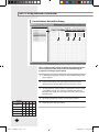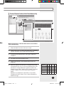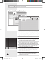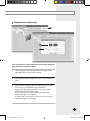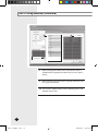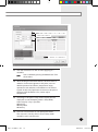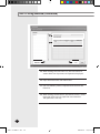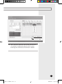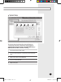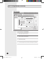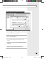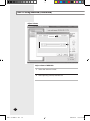
1
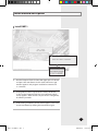
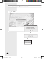
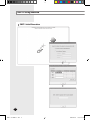
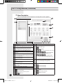
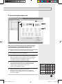
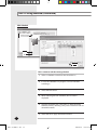
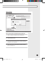
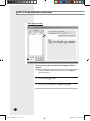
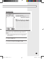
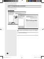
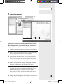
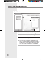
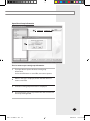
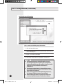
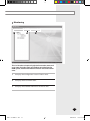
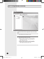
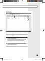
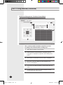
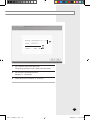
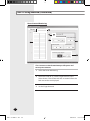
USER’S MANUAL MST-P1W0 MST-P1WU0 SNET-i E DB98-25695A(1) SNET-i-IB-25695-1.indd 57 2006-04-17 ソタネト 2:46:29 Contents Install Method and Update INSTALL SNET-I . . . . . . . . . . . . . . . . . . . . . . . . . . . . . . . . . . . . . . . . . . . . . . . . . . . . . . . . . . . . . . . . . . . 3 UPDATE SNET-I . . . . . . . . . . . . . . . . . . . . . . . . . . . . . . . . . . . . . . . . . . . . . . . . . . . . . . . . . . . . . . . . . . . 4 SNET-i Using Method SNET-I INITIAL EXECUTION . . . . . . . . . . . . . . . . . . . . . . . . . . . . . . . . . . . . . . . . . . . . . . . . . . . . . . . . . . 6 MENU DISCRIPTION . . . . . . . . . . . . . . . . . . . . . . . . . . . . . . . . . . . . . . . . . . . . . . . . . . . . . . . . . . . . . . . . 8 CONTROL INDIVIDUAL INDOOR UNIT. . . . . . . . . . . . . . . . . . . . . . . . . . . . . . . . . . . . . . . . . . . . . . . . . . . . 9 CONTROL INDOOR UNIT WITHIN GROUP. . . . . . . . . . . . . . . . . . . . . . . . . . . . . . . . . . . . . . . . . . . . . . . . .10 CONTROL SEVRAL INDOOR UNIT SIMULTANEOUSLY . . . . . . . . . . . . . . . . . . . . . . . . . . . . . . . . . . . . . . .11 CONTROL WHILE VIEWING ALL INDOOR UNIT . . . . . . . . . . . . . . . . . . . . . . . . . . . . . . . . . . . . . . . . . . . .12 TEMPERATURE LIMITS SETUP . . . . . . . . . . . . . . . . . . . . . . . . . . . . . . . . . . . . . . . . . . . . . . . . . . . . . . . . . .13 SCHEDULE MANAGEMENT . . . . . . . . . . . . . . . . . . . . . . . . . . . . . . . . . . . . . . . . . . . . . . . . . . . . . . . . . . . .14 Create New Schedule . . . . . . . . . . . . . . . . . . . . . . . . . . . . . . . . . . . . . . . . . . . . . . . . . . . . . . . . . . . . . . . 15 Edit Schedule . . . . . . . . . . . . . . . . . . . . . . . . . . . . . . . . . . . . . . . . . . . . . . . . . . . . . . . . . . . . . . . . . . . . . . . 22 Delete Schedule . . . . . . . . . . . . . . . . . . . . . . . . . . . . . . . . . . . . . . . . . . . . . . . . . . . . . . . . . . . . . . . . . . . . 23 Start Apply Schedule . . . . . . . . . . . . . . . . . . . . . . . . . . . . . . . . . . . . . . . . . . . . . . . . . . . . . . . . . . . . . . . 24 Stop Apply Schedule . . . . . . . . . . . . . . . . . . . . . . . . . . . . . . . . . . . . . . . . . . . . . . . . . . . . . . . . . . . . . . . 25 Stop All Schedule . . . . . . . . . . . . . . . . . . . . . . . . . . . . . . . . . . . . . . . . . . . . . . . . . . . . . . . . . . . . . . . . . . . 26 GROUP MANAGEMENT . . . . . . . . . . . . . . . . . . . . . . . . . . . . . . . . . . . . . . . . . . . . . . . . . . . . . . . . . . . . . .27 Move Indoor Unit . . . . . . . . . . . . . . . . . . . . . . . . . . . . . . . . . . . . . . . . . . . . . . . . . . . . . . . . . . . . . . . . . . . 28 Open/Save Group Information . . . . . . . . . . . . . . . . . . . . . . . . . . . . . . . . . . . . . . . . . . . . . . . . . . . . . 29 Initialize Group Information . . . . . . . . . . . . . . . . . . . . . . . . . . . . . . . . . . . . . . . . . . . . . . . . . . . . . . . . 30 MONITORING . . . . . . . . . . . . . . . . . . . . . . . . . . . . . . . . . . . . . . . . . . . . . . . . . . . . . . . . . . . . . . . . . . . . . .31 View Indoor Unit Structure . . . . . . . . . . . . . . . . . . . . . . . . . . . . . . . . . . . . . . . . . . . . . . . . . . . . . . . . . 32 View Error Log . . . . . . . . . . . . . . . . . . . . . . . . . . . . . . . . . . . . . . . . . . . . . . . . . . . . . . . . . . . . . . . . . . . . . . 33 View Detailed Information . . . . . . . . . . . . . . . . . . . . . . . . . . . . . . . . . . . . . . . . . . . . . . . . . . . . . . . . . . 34 POWER MANAGEMENT . . . . . . . . . . . . . . . . . . . . . . . . . . . . . . . . . . . . . . . . . . . . . . . . . . . . . . . . . . . . . .35 Peak Power Management-Priority Control Mode . . . . . . . . . . . . . . . . . . . . . . . . . . . . . . . . . . . 36 Peak Power Management-Circulation Control Mode . . . . . . . . . . . . . . . . . . . . . . . . . . . . . . . 38 Power Amount Monitoring . . . . . . . . . . . . . . . . . . . . . . . . . . . . . . . . . . . . . . . . . . . . . . . . . . . . . . . . . 40 TRACKING . . . . . . . . . . . . . . . . . . . . . . . . . . . . . . . . . . . . . . . . . . . . . . . . . . . . . . . . . . . . . . . . . . . . . . . . .42 DMS IP SETUP . . . . . . . . . . . . . . . . . . . . . . . . . . . . . . . . . . . . . . . . . . . . . . . . . . . . . . . . . . . . . . . . . . .44 CHANGE PASSWORD . . . . . . . . . . . . . . . . . . . . . . . . . . . . . . . . . . . . . . . . . . . . . . . . . . . . . . . . . . . . . . . .45 SYNCHRONIZE TIME . . . . . . . . . . . . . . . . . . . . . . . . . . . . . . . . . . . . . . . . . . . . . . . . . . . . . . . . . . . . . . . . .46 SYSTEM SETUP . . . . . . . . . . . . . . . . . . . . . . . . . . . . . . . . . . . . . . . . . . . . . . . . . . . . . . . . . . . . . . . . . . . . .47 Adjust Date/Time . . . . . . . . . . . . . . . . . . . . . . . . . . . . . . . . . . . . . . . . . . . . . . . . . . . . . . . . . . . . . . . . . . . 48 Screen Brightness and Battery Protection Time Setup . . . . . . . . . . . . . . . . . . . . . . . . . . . . . . 49 Adjust Volume . . . . . . . . . . . . . . . . . . . . . . . . . . . . . . . . . . . . . . . . . . . . . . . . . . . . . . . . . . . . . . . . . . . . . . 50 Web-PAD IP Setup . . . . . . . . . . . . . . . . . . . . . . . . . . . . . . . . . . . . . . . . . . . . . . . . . . . . . . . . . . . . . . . . . . 51 Adjust Stylus of WEB-PAD . . . . . . . . . . . . . . . . . . . . . . . . . . . . . . . . . . . . . . . . . . . . . . . . . . . . . . . . . . . 52 Treatment before Error Confirmation E-2 SNET-i-IB-25695-1.indd 2 2006-04-17 ソタネト 2:46:17 Install Method and Update Install SNET-i 1 Put the Compact Flash Card into the upper part of a board and press the reset button. At this time, below message window appears and program installation continues for 2~3 minutes. 2 If recognition of the Compact Flash Card by the board is slow or the Compact Flash Card is not inserted, above screen appears. After normal Compact Flash is recognized, installation proceeds. 3 If fails during installation, above screen appears. User must restart installation by clicking the reset button again. E-3 SNET-i-IB-25695-1.indd 3 2006-04-17 ソタネト 2:46:18 Install Method and Update (Continued) Update SNET-i E-4 SNET-i-IB-25695-1.indd 4 2006-04-17 ソタネト 2:46:18 Make program update when files are damaged or a new version is launched. 1 Prepare a Compact Flash Card having all 4 configuration files of SNET-i. 2 Put the Compact Flash Card into the upper part of a board and press the reset button. 3 If selecting ‘YES,’ upgrade proceeds. If selecting ‘NO’, upgrade does not proceed and the preexisted program executes or if there is no preexisted program or program is damaged, an error message appears. 4 Press ‘OK’ to confirm to proceed the upgrade. 5 When upgrade is completed, SNET-i is started. 6 If upgrade is failed, the error message on the left appears. User checks the Compact Flash Card and makes upgrade again by pressing the reset button. E-5 SNET-i-IB-25695-1.indd 5 2006-04-17 ソタネト 2:46:18 SNET-i Using Method SNET-i Initial Execution Click ! E-6 SNET-i-IB-25695-1.indd 6 2006-04-17 ソタネト 2:46:18 1 When restart after installing the SNET-i program to the Web-Page, the Stylus Adjustment screen appears and user set the coordinates values of the screen by a pen. 2 Set an IP of Web-Pad. 3 SNET-i software set an IP for DMS to connect. After inputting the DMS IP, execute ‘Status Check.’ Only in case at least one Connection Status and Authentication Status of DMS displays ‘O’ mark which means normal connection, next step can be preceded. If ‘X’ marks appear, perform ‘Status Check’ again. 4 If performing Status Check, system requests an Install Password of DMS that the connection status is ‘O.’ When inputting a password of relevant DMS and pressing the OK button, authentication procedure is performed. If the password is incorrect, authentication is failed. E-7 SNET-i-IB-25695-1.indd 7 2006-04-17 ソタネト 2:46:18 SNET-i Using Method (Continued) Menu Description After completing the initial execution normally, below screen appears. 2 1 4 3 5 6 7 9 8 10 Content Control Menu (Individual control, Multi-Control, Total Control) Other function menu (Schedule, Group Management, Monitoring, Power Management, System Management) Indoor unit and group list display window Current selected indoor unit and group display window Selection window for operation status of current selected indoor unit, Current Temperature display, and Set Temperature Selection window for Exclude Setup of current selected indoor unit Selection window for Mode, Fan Speed, and Air Flow Operation status display window for current selected indoor unit Inquiring button for Peak Power Information and Schedule of current selected indoor unit and Peak Power status Temperature Limits Setup display System Date display Power amount of power distributor display : Not installed PIM No. 1 2 3 4 5 6 7 8 9 10 11 12 12 13 14 15 16 11 : PIM install and normal operation / : PIM error Content No. PEAK setup display : No PEAK setup : Not operated 13 14 / : In case Peak transmitter is out of order / / / : Priority Control Mode LEVEL 0, 1, 2, 3 / / / : Circulation Control Mode CLASS 0, 1, 2, 3 DMS Connection Status (Green: normal connection, Orange: error, Dark grey: not registered) Control setup display of Remote Control 15 : Remote Control ON : Remote Control OFF Power Display 16 : Power cable connection : Battery connection E-8 SNET-i-IB-25695-1.indd 8 2006-04-17 ソタネト 2:46:19 Control Individual Indoor Unit 1 2 4 3 5 When start is normally operated, below Individual Control screen appears first. The Individual Indoor Unit Control is a function that one group controls one indoor unit. 1 Select one indoor unit that controls by one group. 2 The selected indoor unit is displayed. 3 Set On/OFF status and Set Temperature of the selected indoor unit. But in case Fan, cannot adjust temperature. If Temperature Limits Setup(Refer to page 13) is set, can adjust temperature within the range. 4 Can select the Upper and Lower Temperature Limits Setup, Remote Control Setup, and Peak Circulation Control Setup of the relevant indoor unit. (CHECK: Set, UNCHECK : Unset) 5 Select the Mode, Fan Speed, and Air Flow. (If Mode is Dry and Auto, selection of Fan Speed is restricted to Auto; if Mode is Fan, cannot select Auto among Fan Speed.) Mode Fan Speed Auto Low Mid High Cool o o o o Auto o x x x Dry o x x x Fan x o o o Heat o o o o E-9 SNET-i-IB-25695-1.indd 9 2006-04-17 ソタネト 2:46:19 SNET-i Using Method (Continued) Control Indoor Unit within Group 1 2 3 4 5 This is a function that controls an indoor unit after viewing the current operation status of the indoor unit that belongs to a group by selecting a specific group. Mode Fan Speed Auto Low Mid High Cool o o o o Auto o x x x Dry o x x x Fan x o o o Heat o o o o 1 If selecting one group, all indoor units which belongs that group appear. 2 Choose one indoor unit and select operation On/Off. (All control can be possible only in case status is ‘On.’) 3 Set temperature. (At this time, if Temperature Limits Setup is set (Refer to page 13), can be set within that limited temperature range. Also if in the Fan mode, cannot adjust temperature.) 4 By clicking the Mode, select a mode among items. 5 Select Air Flow and Fan Speed. E-10 SNET-i-IB-25695-1.indd 10 2006-04-17 ソタネト 2:46:20 Control Several Indoor Unit Simultaneously 1 5 2 3 6 4 Multi-Control menu is a function that controls several indoor units simultaneously. 1 Select the Multi-Control on the main screen. 2 Select indoor units to control simultaneously. If selecting a group, all indoor units in the group are selected. 3 If selecting the selected indoor unit again, selection is cancelled. 4 Can select and cancel all indoor units. 5 The list and number of the selected indoor units are displayed. 6 Select the operation On/Off status, Set Temperature, Mode, Fan Speed, Air Flow, and so on for the selected indoor units. All controls can be possible when operation mode is ‘On’. If Mode is Dry and Auto, selection of Fan Speed is restricted to Auto; if Mode is Fan, cannot select Auto among Fan Speed. If Mode is Fan, temperature adjustment is not possible; if Temperature Limits Setup is set, can adjust temperature within the range. Mode Fan Speed Auto Low Mid High Cool o o o o Auto o x x x Dry o x x x Fan x o o o Heat o o o o E-11 SNET-i-IB-25695-1.indd 11 2006-04-17 ソタネト 2:46:20 SNET-i Using Method (Continued) Control while Viewing All Indoor Unit 1 2 3 5 6 Total Control menu is a menu to view all status (Operation On/Off, Peak Control, Error Status, Assign indoor unit or not) of connected indoor units at a look. Also, users can set the Remote Control Setup and the Upper & Lower Temperature Setup for all indoor units. Color Mean Blue Power On White Power Off Green Peak Power Control Status Red Indoor Unit Error Occur Grey No assigned indoor unit Yellow 1 Select Total Control on the main screen. 2 One unit shows an indoor unit that belongs to a group (Limited to maximum 16 units) and color and letter of each unit show the meaning shown on the left. 3 When selecting an indoor unit, the name of that indoor unit is displayed and user can control operation On/Off. 4 When selecting a group, user can see the names of all indoor units which belong to that group. 5 When selecting the Remote Control Setup button, user can control whether use of remote control or not for an indoor unit. (This is the same function as Temperature Limits Setup on the right page.) 6 When selecting the Upper•Lower Temperature Limits Setup, user can control temperature range which is selectable in an indoor unit. Network Error Status R Remote Control Exception C Upper•Lower Temperature Limits Setup Exception P Peak Power Setup Exception E-12 SNET-i-IB-25695-1.indd 12 2006-04-17 ソタネト 2:46:21 Temperature Limits Setup 1 2 3 This is a function to restrict temperature selection by setting the upper and lower temperature limits. 1 Click the Upper•Lower Temperature Limits Setup on the right upper part of Total Control screen. 2 Set the Upper•Lower Temperature Limits for an individual room. 3 Select whether applying the set temperature to an indoor unit or not. For the individual room which set temperature after selecting Apply, user can change it within the temperature limit range. If set Cancel, in case of Heat mode, user can change within the range 16~30 degree; in other cases, Cool, Auto, Dry, and Fan, user can change within the range 18~30 degree. E-13 SNET-i-IB-25695-1.indd 13 2006-04-17 ソタネト 2:46:21 SNET-i Using Method (Continued) Schedule Management 1 2 3 4 5 6 User can add, edit, and delete schedules for the DVM operation or can select whether applying selected schedule or not. Also, user can set Schedule Period when creating a schedule and can select and apply an indoor unit to apply, Date, and Exception Day to the Event List. 1 Select the Schedule on the main menu. 2 On the Schedule List, pre-registered schedule and operation status are displayed. 3 When selecting a schedule from the Schedule List, the Repeat Period, Schedule Status, and Contents for the relevant schedule are displayed. 4 Can see an indoor unit which the selected schedule will be applied. 5 Can see the Exception Day for the selected schedule. 6 Can create new schedules or stop the current schedule in progress and can edit, delete, apply, and cancel the selected schedule. E-14 SNET-i-IB-25695-1.indd 14 2006-04-17 ソタネト 2:46:21 Create New Schedule 2 1 For an example, use the Repeat Weekly. 1 Select the New Schedule. 2 Select a repeat period of the new schedule. E-15 SNET-i-IB-25695-1.indd 15 2006-04-17 ソタネト 2:46:21 SNET-i Using Method (Continued) 3 4 3 Input a schedule name. 4 Select the Start Day and Finish Day that a schedule is applied by clicking the calendar just beside of input space. The Finish Day of a schedule period must be next to the Start Day. E-16 SNET-i-IB-25695-1.indd 16 2006-04-17 ソタネト 2:46:21 7 6 5 5 Click the Exception Day Setup button. 6 Set the exception day of a schedule by moving the date by using buttons beside year and month. Schedule content is not applied on the selected date. Among dates which set the exception day, only the exception days in the schedule period are corresponded. 7 Can cancel the specific exception day from the selected exception day list. E-17 SNET-i-IB-25695-1.indd 17 2006-04-17 ソタネト 2:46:22 SNET-i Using Method (Continued) 9 10 8 8 When selecting the Select Indoor Unit button which a schedule will be applied, the Select Indoor Unit screen is shown. 9 When selecting an indoor unit or a group, all indoor units in a group are selected. 10 Can cancel a specific indoor unit by selecting it from the selected indoor units. E-18 SNET-i-IB-25695-1.indd 18 2006-04-17 ソタネト 2:46:22 13 14 12 11 11 Click the Add button to add an event applying to a schedule. Note User can delete by pressing the Delete button form the set event. 12 When clicking the Add Event button, the basic event is added as shown in the picture. In this place, user can decide operation On/Off time, temperature setup, operation mode selection, and whether use of remote control. At this time, Operation On time must be prior to Off time and if the Mode is Fan, cannot adjust temperature. 13 According to the period setup, below repeat period is displayed. In case the repeat period is Every Week, event setup by a day is possible. Everyday Every week One day 14 User can save set events or can open preset event. The save unit is one day. Also in case of every week schedule, save in one day unit. E-19 SNET-i-IB-25695-1.indd 19 2006-04-17 ソタネト 2:46:22 SNET-i Using Method (Continued) 16 15 17 18 15 When clicking the Save Event List, the Save Event List screen which one day events are inputted is displayed. 16 Input the Event Name and Information. 17 User can delete a previous inputted event list from the Event List. 18 When clicking the OK button, the relevant event is saved. Using the ‘Open,’ user can open the saved event list. The open unit is one day. E-20 SNET-i-IB-25695-1.indd 20 2006-04-17 ソタネト 2:46:22 19 19 When selecting the OK button after inputting all information of a schedule, a schedule with relevant name is created. If selecting the Cancel button, all information is deleted. E-21 SNET-i-IB-25695-1.indd 21 2006-04-17 ソタネト 2:46:22 SNET-i Using Method (Continued) Edit Schedule 1 3 2 6 This is a menu to edit the existing schedule 1 Select a schedule to edit from the Schedule List. 2 In case the schedule is in progress, user can edit after canceling it. 3 Select the Edit button. 4 When selecting the Edit Schedule, above screen is displayed. 5 The Edit Schedule is the same menu as`New Schedule’; therefore, edit by selecting some parts to edit from the set schedule contents. 6 Select the OK to apply the edited contents. E-22 SNET-i-IB-25695-1.indd 22 2006-04-17 ソタネト 2:46:22 Delete Schedule 1 3 4 2 This is a menu to delete a schedule from the Schedule List 1 Select a schedule to delete from the Schedule List. 2 Click the Delete button. 3 A message window which questions whether deleting a schedule or not is displayed. 4 When clicking the OK, the relevant schedule is deleted from the Schedule List. E-23 SNET-i-IB-25695-1.indd 23 2006-04-17 ソタネト 2:46:23 SNET-i Using Method (Continued) Start Apply Schedule 1 2 This is a menu to apply a schedule that the Apply schedule is stopped. 1 Select a schedule which current status is in Stop () from the Schedule List. 2 Click the Apply ( ) button. 3 The status is changed from Stop () to Apply( ). E-24 SNET-i-IB-25695-1.indd 24 2006-04-17 ソタネト 2:46:23 Stop Apply Schedule 1 2 This is a menu to stop a schedule that the Apply schedule is in progress. 1 Select a schedule which current status is in Apply( ) from the Schedule List. 2 Click the Stop() button. 3 The status is changed from Apply( ) to Stop(). E-25 SNET-i-IB-25695-1.indd 25 2006-04-17 ソタネト 2:46:23 SNET-i Using Method (Continued) Stop All Schedule 1 This is a menu to stop all schedules in progress in the Schedule List. 1 Click the Stop All button. E-26 SNET-i-IB-25695-1.indd 26 2006-04-17 ソタネト 2:46:23 Group Management 1 3 4 5 6 Control groups and indoor units by putting them in a logical group. Perform functions, the Create New Group, Delete Group, Move Group, Rename Group, Initialize Group, Save Current Group Setting, and Open Previous Group Setting. 1 Select the Group Management menu on the main menu. 2 When selecting the Group Management, as shown in the picture 40, the Group Management main screen is displayed. 3 Using the ‘Up’ and ‘Down’ buttons, can move the position of a group or an indoor unit to up and down. When the selected item is only one, user can use this menu. In case of the indoor unit, can move only within the relevant group. 4 When selecting the ‘New Group,’ a new group is created. Using the soft keyboard, can edit the group name. 5 When selecting the ‘Delete Group’ after selecting a group, can delete the relevant group. At this time, if an indoor unit is included in the group to be deleted, user cannot delete it. After creating an empty group and moving the indoor unit to this group, can delete it. 6 When selecting the ‘Rename’ after selecting an indoor unit or a group, can change the name of them. SNET-i-IB-25695-1.indd 27 E-27 2006-04-17 ソタネト 2:46:23 SNET-i Using Method (Continued) Move Indoor Unit 1 3 2 This is a menu to move an indoor unit to the other group. 1 Select an indoor unit to move to the other group. 2 Select the ‘To Other Group’ button. 3 When the Group List window is shown, select a group wants to move and click the OK. The maximum number of movable indoor units per a group is 16. Cannot move to a group that already 16 units of indoor unit are included. E-28 SNET-i-IB-25695-1.indd 28 2006-04-17 ソタネト 2:46:24 Open/Save Group Information 1 4 2 This is a menu to open saved group information. 1 The Open button opens the latest saved group information. At this time if there is no saved file, user cannot open it. 2 When a message is displayed, check and click the most recent saved date. 3 The latest saved group information is displayed. 4 The Save button saves group information that is formed in the Group Management. E-29 SNET-i-IB-25695-1.indd 29 2006-04-17 ソタネト 2:46:24 SNET-i Using Method (Continued) Initialize Group Information 1 2 This is a menu to initialize group information. 1 Click the Initialize button. 2 A message showing that the current Group information is saved is displayed. 3 Input a password to initialize. 4 The Group Information is displayed as initial state. E-30 SNET-i-IB-25695-1.indd 30 Caution Even though the group setting information is saved, if tracking is happened or if opening the configuration information again because the number of units to install is different, the saved installation information is disappeared. Even though network status is changed to Error status, if not requesting the information to the DMS, the network Error status is not reflected. Before coming out from the Group Management menu, the changes of different menu are not reflected. When changing the name of a group or an indoor unit, cannot use special characters or more than 15 letters. 2006-04-17 ソタネト 2:46:24 Monitoring 2 1 3 This is a function to inquire the physical connection status and error status for indoor units and outdoor units that form the DVM system, detailed information of indoor units and outdoor units. 1 It displays the configuration status of indoor units. 2 It displays the Error Information. 3 It displays the Detailed Information of indoor units. E-31 SNET-i-IB-25695-1.indd 31 2006-04-17 ソタネト 2:46:24 SNET-i Using Method (Continued) View Indoor Unit Structure 1 2 It displays the hierarchical configuration status of an indoor unit. 1 Select the Physical Connection status 2 Select the relevant DMS and CAUR When tracking is finished as the Group Mode, displays the connection status in the order of DMS-CAUR-indoor unit. When tracking is finished as the Room Mode, displays the connection status in the order of DMS-CAUR-transmitter-indoor unit. E-32 SNET-i-IB-25695-1.indd 32 2006-04-17 ソタネト 2:46:24 View Error Log 1 3 This is a menu to inquire error information. 1 Select the Error Log. 2 If there is error occurred information, displays error details as shown in above picture. At this time, if there is the DMS connection error, check the connection status in the System Management. 3 For more detailed information about the relevant error, select ‘Detailed Information.’ E-33 SNET-i-IB-25695-1.indd 33 2006-04-17 ソタネト 2:46:24 SNET-i Using Method (Continued) View Detailed Information 1 3 2 User can see detailed information about an indoor unit and an outdoor unit. 1 Select the View Detailed Information. 2 Select an indoor unit which a user wants to view the detailed information. 3 The detailed information for an indoor unit and an outdoor unit is displayed. But when DMS connection error is occurred, select again after checking the connection status in the System Management. If the current completed tracking mode is the Group Tracking Mode, cannot check the detailed information. E-34 SNET-i-IB-25695-1.indd 34 2006-04-17 ソタネト 2:46:24 Power Management 1 1 This is a function to mange the Peak power and power distribution or to monitor the power. Operation of Peak power management is set to operate with one mode between the Priority Control Mode and Circulation Control Mode. According to the Priority Control Level or Circulation Control Class, it consists of a setup part forming the indoor units that become a target of Peak power management. The Power Distribution performs a function to save the power distribution data that is received from the DMS (Data Management Server) to the external storage devices and files. With the power monitoring, user can know the maximum possible power and power amount. E-35 SNET-i-IB-25695-1.indd 35 2006-04-17 ソタネト 2:46:25 SNET-i Using Method (Continued) Peak Power Management-Priority Control Mode 1 5 6 4 3 The Priority Control Mode is an operation mode of Peak power to operate an indoor unit which belongs to corresponding level when the Peak transmitter reaches power amount corresponding to each level by including each indoor unit to the Level 1, 2, 3, or Exception. (In the order Level123) 1 Select the Priority Control Mode. 2 The current priority control mode is displayed on the screen. 3 If the priority control mode is in progress, running level is displayed as shown in the picture. 4 Can see an indoor unit that is set to Level 1, 2, and 3 or Exception. 5 When selecting and clicking the Start, the relevant mode is progressed. 6 To change the Priority Control Mode, click the button. E-36 SNET-i-IB-25695-1.indd 36 2006-04-17 ソタネト 2:46:25 9 8 7 7 Can set the Priority Level by the indoor unit. At this time when selecting a level of a group, the level is applied to all indoor units that belong to the relevant group simultaneously. Basically, all indoor units are classified to Exception. 8 If set the Level, can see the set indoor units to the relevant Level. (Exception: Not applied to Peak setup, LEVEL1: Priority level 1, LEVEL2: Priority level 2, LEVEL3: Priority level 3) 9 Set the attributes of the Priority Control Mode. (Heat mode: Switch to Fan mode, temperature 16, OFF setup – Cool mode: Switch to Fan mode ) E-37 SNET-i-IB-25695-1.indd 37 2006-04-17 ソタネト 2:46:25 SNET-i Using Method (Continued) Peak Power Management-Circulation Control Mode 5 1 3 6 4 2 This is a menu to make circulation control the set classes according to the Peak transmitter reaching steps. 1 Select the Circulation Control Mode. 2 If the Circulation Control Mode is operated, the class in progress is displayed. (It operates at the Peak power point.) 3 The current set circulation control mode is displayed. 4 The indoor units that belong to the Exception and Classes are displayed. 5 Can start or stop the Circulation Control Mode with set value. 6 To change the set value of current circulation mode, press the Change Setup button. E-38 SNET-i-IB-25695-1.indd 38 2006-04-17 ソタネト 2:46:25 7 8 9 7 Set a switch mode in the Heat mode. For heating, operation mode is fixed to the Fan mode. 8 Set the value of Circulation Period. (Between 3 ~ 10 minutes) 9 Select the Use Class Number. (2~ 8 classes) E-39 SNET-i-IB-25695-1.indd 39 2006-04-17 ソタネト 2:46:25 SNET-i Using Method (Continued) Power Amount Monitoring 1 6 3 2 5 4 This is a menu to view the maximum possible power and current power amount. 1 Select the Power Monitoring. 2 The Alarm Level (0~3), Current Target Demand, Total Active Power, Current Demand that are received from the Peak transmitter are displayed. 3 Set the Target Demand. E-40 SNET-i-IB-25695-1.indd 40 2006-04-17 ソタネト 2:46:25 4 Set the Alarm Level Control Period. 5 Based on the Target Demand, changed amount of the Total Active Power and Current Demand is displayed. 6 If the Total Active Power or Current Demand is greater than the Target Demand, an image is changed to red color. Caution The Priority Control Mode and the Circulation Control Mode cannot perform at the same time. If operating one mode while the other mode is in progress, previous mode is stopped. If an indoor unit does not become a target of the Circulation Control mode, must check the Circulation Control Exception under the Individual Control. To perform the Peak power and Power Monitoring, one representative DMS must connect to the Peak transmitter. If not, only power distribution menu can be usable. Even though network status is changed to Error status, if not requesting the information to the DMS, the network Error status is not reflected. Before coming out from the Power Management menu, the other setting changes besides the Power Management are not reflected. E-41 SNET-i-IB-25695-1.indd 41 2006-04-17 ソタネト 2:46:26 SNET-i Using Method (Continued) Tracking 1 2 3 4 This is a function to receive information of all devices that form the DVM system. 1 Select the System Management. 2 Select the ‘Tracking.’ 3 The current tracking mode is displayed. 4 To change the current set tracking mode, select ‘Change Tracking Mode.’ E-42 SNET-i-IB-25695-1.indd 42 2006-04-17 ソタネト 2:46:26 5 To change the tracking mode, input a password. 6 After a correct password is inputted, the Change Mode window is shown. When selecting a tracking mode and clicking the OK, the tracking mode is changed. 7 Select the Start Tracking. At this time, tracking mode is the current tracking mode. 8 When a message asking whether the tracking is in progress or not is displayed, select the OK. 9 During tracking, cannot select other menus. 10 After completing Tracking, system is configured with new information. E-43 SNET-i-IB-25695-1.indd 43 2006-04-17 ソタネト 2:46:26 SNET-i Using Method (Continued) DMS IP Setup 1 4 2 5 3 This is a menu to connect DMS by inputting a DMS IP. 1 Select the ‘System Management’ menu. 2 Input a DMS IP. (Can connect the maximum 4 DMS IP) 3 Click the Status Check button. 4 If the connection status and authentication status are displayed as ‘0,’ it connects correctly. 5 Green light is on at the connection status icon of the status display bar. Caution When the IP address is as below, an error message is displayed. - If inputting a duplicated IP - If inputting a IP of unconnected DMS - If the IP input range is not in 0~255 - If the IP format is not matched For the IP address, use IPV5. Can control only DMS that both the connection status and authentication status are ‘0.’ When there is no after serviceman password, E-44 SNET-i-IB-25695-1.indd the authentication status displays as ‘X’ and must input a password. 44 2006-04-17 ソタネト 2:46:27 Change Password 1 2 This is a menu to change a password for applying to the system. 1 Select the ‘System Management.’ 2 Input the current password (password before changing). 3 Input a password to change and input one more time for confirmation. 4 Click the Apply Change button. Caution Only when all three inputted passwords are correct, change is reflected. Even though network status is changed to Error status, if not requesting the information to the DMS, the network Error status is not reflected. Before coming out from the menu, the changes of the other menus are not reflected. E-45 SNET-i-IB-25695-1.indd 45 2006-04-17 ソタネト 2:46:27 SNET-i Using Method (Continued) Synchronize Time 1 5 4 This is a menu to synchronize time that applies to the difference between the SNET-i and DMS. 1 Select the ‘System Management.’ 2 Check the DMS Time (Sever Time) and SNET-i Time (Device Time). 3 If setting the DMS Time to SNET-i Time, click the ‘Set Server Time to Device Time’ button. If it processed normally, system time is changed. 4 If setting the SNET-i Time to DMS Time, click the ‘Set Device Time to Server Time’ button. At this time, the password input window is displayed. When inputting the system admin password, server time is changed. 5 If both DMS Time (Server Time) and SNET-i Time (Device Time) are not incorrect, can change SNet-i Time manually by clicking the ‘Set Device Time’ button. For more detailed information, refer to page 48 ’ Adjust Date/Time.’ E-46 SNET-i-IB-25695-1.indd 46 2006-04-17 ソタネト 2:46:27 System Setup 1 2 3 4 5 The System Setup is performed by a external button no. 1 and operates functions of Date/Time Setup, Brightness Control, Volume Control, IP setup, and Stylus adjustment of WEB-PAD that the SNET-i software is running. 1 Set date and time of the system. 2 Set the screen brightness and battery power protection time. 3 Adjust the volume of the WEB-PAD. 4 Set an IP of the WEB-PAD. 5 Adjust the Stylus. E-47 SNET-i-IB-25695-1.indd 47 2006-04-17 ソタネト 2:46:27 SNET-i Using Method (Continued) Adjust Date/Time 1 3 2 4 Set date and time of the WEB-PAD. 1 Select the ‘Date/Time’ button. 2 Select a date on the calendar. 3 Perform time setup. 4 Set the changed date and time by clicking the OK button. E-48 SNET-i-IB-25695-1.indd 48 2006-04-17 ソタネト 2:46:27 Screen Brightness and Battery Protection Time Setup 1 2 3 4 5 Set the screen brightness and battery power protection time. 1 Select the ‘Brightness Control’ menu. 2 Adjust the screen brightness. 3 Set the screen switching time for protection of the battery. 4 Select whether applying the screen protection switching time or not. 5 Apply the changed contents by clicking the OK. E-49 SNET-i-IB-25695-1.indd 49 2006-04-17 ソタネト 2:46:28 SNET-i Using Method (Continued) Adjust Volume 1 2 Adjust volume of WEB-PAD. 1 Select the ‘Volume Control.’ 2 After adjusting volume, click the ‘OK.’ E-50 SNET-i-IB-25695-1.indd 50 2006-04-17 ソタネト 2:46:28 Web-PAD IP Setup 1 2 This is a menu to set an IP of the WEB-PAD. 1 Select the ‘IP Setup.’ 2 Select one between the DHCP (Dynamic IP address configuration) and Direct IP input. 3 In case of Direct IP input, enter the IP address, subnet mask, and gateway. 4 Set the Web-PAD IP by clicking the OK. 5 If an IP is inputted newly or changed, restart the system. E-51 SNET-i-IB-25695-1.indd 51 2006-04-17 ソタネト 2:46:28 SNET-i Using Method (Continued) Adjust Stylus of WEB-PAD Adjust the Stylus of the WEB-PAD. Click 1 Select the ‘Stylus Adjustment.’ 2 Click the ‘Start’ button. 3 Adjust the screen by clicking the center of the cross. ! E-52 SNET-i-IB-25695-1.indd 52 2006-04-17 ソタネト 2:46:28 Treatment before Error Confirmation Item Question When initial execution During Control Other Answer Cannot communicate with the DMS. Check the IP of SNET- i and DMS. If the IP is correct, check the DMS status. Cannot open the indoor unit information. Perform tracking in the Configuration. Cannot control an indoor unit. Check the LAN LED of SNET-i. Check the communication status of DMS Even though not operating an indoor unit, it turns on or off automatically. Check whether the schedule control or Peak power control is operated or not. Check whether the DMS system time is matched with current time. Peak control is not performed normally. Check the communication status of DMS. In case DMS is not normal, Peak control is not performed. Screen is paused. Click the Reset button on the left side of the SNet-i. E-53 SNET-i-IB-25695-1.indd 53 2006-04-17 ソタネト 2:46:28 MEMO E-54 SNET-i-IB-25695-1.indd 54 2006-04-17 ソタネト 2:46:28 E-55 SNET-i-IB-25695-1.indd 55 2006-04-17 ソタネト 2:46:28 SNET-i-IB-25695-1.indd 56 2006-04-17 ソタネト 2:46:29