1
INSTALLATION
MANUAL
Wall Mounted Type Series
Neo Forte : AVXWN
NHNH
Air Conditioner
E DB98-31755A(2)
AVXWN@@_IM_E_31755_5.08.10.indd 25
2010-5-8 10:35:05
AVXWN@@_IM_E_31755_5.08.10.indd 1
2010-5-8 10:34:14
Contents
PREPARING FOR INSTALLATION
Safety Precautions . . . . . . . . . . . . . . . . . . . . . . . . . . . . . . . . . . . . . . . . . . . . . . . . . . 3
Choosing the Installation Location . . . . . . . . . . . . . . . . . . . . . . . . . . . . . . . . . . 5
Accessories . . . . . . . . . . . . . . . . . . . . . . . . . . . . . . . . . . . . . . . . . . . . . . . . . . . . . . . . . 6
INSTALLING THE AIR CONDITIONER
Fixing the Installation Plate . . . . . . . . . . . . . . . . . . . . . . . . . . . . . . . . . . . . . . . . . 7
Purging the Indoor Unit . . . . . . . . . . . . . . . . . . . . . . . . . . . . . . . . . . . . . . . . . . . . 7
EEV Kit Installation . . . . . . . . . . . . . . . . . . . . . . . . . . . . . . . . . . . . . . . . . . . . . . . . . . . 8
Installing and Connecting the Assembly Pipe of the Indoor Unit . . . 12
Cutting or Extending the Pipe . . . . . . . . . . . . . . . . . . . . . . . . . . . . . . . . . . . . . . 13
Installing and Connecting the Drain Hose of the Indoor Unit . . . . . . 14
Changing Direction of the Drain Hose . . . . . . . . . . . . . . . . . . . . . . . . . . . . . . 15
Wiring Work . . . . . . . . . . . . . . . . . . . . . . . . . . . . . . . . . . . . . . . . . . . . . . . . . . . . . . . . 16
Assigning Address to Indoor Unit . . . . . . . . . . . . . . . . . . . . . . . . . . . . . . . . . . . 19
Additional Functions . . . . . . . . . . . . . . . . . . . . . . . . . . . . . . . . . . . . . . . . . . . . . . . . 20
COMPLETING THE INSTALLATION
Performing Leak Test & Insulation . . . . . . . . . . . . . . . . . . . . . . . . . . . . . . . . . . . 21
Final Check and Trial Operation . . . . . . . . . . . . . . . . . . . . . . . . . . . . . . . . . . . . . 22
Providing Information for User . . . . . . . . . . . . . . . . . . . . . . . . . . . . . . . . . . . . . . 23
E-2
AVXWN@@_IM_E_31755_5.08.10.indd 2
2010-5-8 10:34:14
Safety Precautions
Keep this installation manual together with the user’s manual in a handy place so that you can find it whenever
you need to see it after reading this manual thoroughly.
Make sure you read this ‘Safety Precautions’ carefully before installing the product.
Safety Precautions states information that is important to your safety matters. Please follow the instructions
carefully.
WARNING Hazards or unsafe practices that may result in severe personal injury or death.
CAUTION Hazards or unsafe practices that may result in minor personal injury or property damage.
You must install the product by qualified installer. If you install the product on your own or by unqualified
person, Samsung is not responsible for any damages which may occur due to incorrect installation.
Make sure to read the following safety precautions carefully before installation.
Make sure to observe the cautions specified in this manual.
Conduct a test run of the unit after installation and then explain all system functions to the owner.
The indications and meanings are as shown below.
Follow IEC (International Electrotechnical Commission) standards for the power input and
ISO (International Standards Organization) standards for input current.
WARNING
Hazards or unsafe practices that may result in severe personal injury or death.
Installation must be carried
out by a qualified installer.
Do not attempt to repair,
move, modify or reinstall the
unit on your own since such
act may cause fire, electric
shock or water leakage.
Install the unit in a place
where it is strong enough
to hold the product weight.
When installed in place
where it is not strong enough
to withhold the product
weight, the unit could fall
and cause injury.
The unit should be
installed in accordance
with the National Electrical
regulations. Check if the
voltage and the frequency of
the main power supply are
those required for the unit
to be installed and check the
connection. Avoid the use of
an extension cord and do not
share the power outlet with
other appliances. Incomplete
connection, defective
insulation or exceeding the
permissible current may
cause electric shock or fire.
Use the specified wires to
connect the indoor and
outdoor units securely and
attach the wires firmly to the
terminal block connecting
sections so that the pressure
is not applied to the sections.
Inappropriate connection
and fixing could cause fire.
Attach the electrical cover to
the indoor and outdoor unit
securely without any gaps.
If there are any gaps, there is
potential risk of fire or electric
shock due to dust or water.
Make sure to use the part
provided or specified parts for
the installation work. The use
of defective parts could cause
an injury or leakage of water
due to a fire, an electric shock,
the unit falling, etc.
Make sure that the
refrigerant gas does not
leak after completing the
installation.
If the refrigerant gas of
the indoor unit leaks and
comes into contact with the
fan heater, space heater or
stove, harmful gas will be
generated.
Ensure that the national
safety code requirements
have been followed for the
main supply circuit. Ensure
that a proper ground wire is
in place.
Do not connect the ground
to a gas pipe, water pipe,
lightning rod or telephone
grounding. Defective
grounding could cause
electric shock.
Do not install the unit in a
place with direct sunlight,
dangerous substances
or where it is exposed to
inflammable gas leakage
to prevent explosion, fire or
personal injury.
Perform the installation
securely referring to
the installation manual.
Incomplete installation
could cause personal injury
due to fire, electric shock
and water leakage or from
the unit falling.
Before connecting the
power plug and power
receptacle check for dust,
loose or blocked. Make sure
that plug is fully inserted.
Dusted power plug,
blocked or loosened power
receptacle may cause fire
or electric shock. Exchange
the power receptacle if it is
loose.
Check first the following
situations before starting
the operation during the
installation.
- The pipe must be properly
connected and make sure
there is no leakage.
- Service valves must be open.
If compressor is operated
with the service valve
closed, excessive pressure
may damage parts of the
compressor.
If leakage occurs on any of
the connection, air inflow
may also cause excessive
pressure that could lead to
explosion.
E-3
AVXWN@@_IM_E_31755_5.08.10.indd 3
2010-5-8 10:34:14
Safety Precautions (Continued)
WARNING
Hazards or unsafe practices that may result in severe personal injury or death.
Stop the compressor before
disconnecting the refrigerant
pipe for pump-down
operation. If you disconnect
the refrigerant pipe while
compressor is operating with
service valve open, air inflow
will cause excessive pressure
in the refrigerant cycle that
could lead to explosion and
personal injury.
Do not assemble the power
cord on your own, use two
cables together to extend
the cable length or tangle
the cable. Bad connection,
isolation and over voltage may
cause fire or electric shock.
CAUTION
Make sure to turn off the
main power when setting
up the indoor unit electrical
circuit or power cords. There
is a risk of electric shock.
Make sure that proper
circuit breaker and safety
switches are installed.
Install a ground leakage
breaker depending on the
installation place(where it is
humid). If not, it may cause
electric shock.
Do not install the unit by
yourself (owners). Incorrect
installation of the unit could
cause injury due to fire,
electric shock and water
leakage or from the unit
falling. Consult a dealer or a
qualified installer.
Use the unit on a single
outlet circuit. Do not share
the power outlet with other
appliances.
Obtain the consent by a
qualified installer before
connecting the unit to the
power supply system.
Hazards or unsafe practices that may result in minor personal injury or property
damage.
Perform the drainage/piping
work securely according to
the installation manual. If not,
water could drop from the
unit and household goods
could get wet and damaged.
Fasten a flare nut with a
torque wrench as specified
in this installation manual.
When fastened too tight,
a flare nut may break after
a long period of time and
cause refrigerant leakage.
Wear thick gloves during the
installation process.
If not, personal injury
may occur due to the air
conditioner parts.
Be careful not to touch
the outdoor unit inlet or
aluminium pins. You may get
personal injury.
The air conditioner should be
used only for the applications
for which it has been
designed: the indoor unit is
not suitable to be installed in
areas used for laundry.
When installing the indoor
unit, use a stable stool and
watch your steps carefully.
To prevent injury when
accidentally touching the
indoor unit fan, install the
indoor unit at least 2.5m
above the floor level.
Our units must be installed in
compliance with the spaces
indicated in the installation
manual to ensure either
accessibility from both sides
or ability to perform routine
maintenance and repairs. The
units’ components must be
accessible and that can be
disassembled in conditions
of complete safety either for
people or things.
For this reason, where it is
not observed as indicated
into the Installation Manual,
the cost necessary to reach
and repair the unit (in safety,
as required by current
regulations in force) with
slings, trucks, scaffolding or
any other means of elevation
won’t be considered
in-warranty and charged to
end user.
Do not install the outdoor
unit in a place where
animals could live. If an
animal get contact with the
electric parts, damage or
fire may occur. In addition
ask the customer to
maintain a clean installation
place around it.
After completing the
installation run the trial
operation. If no error occurs,
explain to the customer
how to use and clean the air
conditioner according to the
user’s manual. In addition
give the installation manual
and the user’s manual to the
customer.
All of the manufacturing
and packaging material
used for your new appliance
are compatible with the
environment and can be
recycled.
Dispose of the packaging
material in accordance with
the local requirements.
This product is an air
conditioning system and
contains a coolant that must
be recovered and disposed
of in an appropriate way by
qualified personnel. At the
end of the life cycle, take
it to a proper recycling or
disposal center or return it to
the dealer so that it can be
disposed correctly.
Check the unit for damage
that may have taken place
during transportation and do
not install or use damaged
equipment.
E-4
AVXWN@@_IM_E_31755_5.08.10.indd 4
2010-5-8 10:34:15
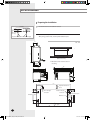
Choosing the Installation Location
Where airflow is not blocked
Where cool air can be distributed throughout the room
Install the refrigerant piping length and the height
difference of both indoor and outdoor units as
indicated in the installation diagram
Wall that prevents vibration and is strong enough to hold the product weight
Out of the direct sunlight
1m or more away from the TV or radio
(to prevent the screen from being distorted or noise from being generated)
As far away as possible from fluorescent and incandescent lights (so that the remote
control can be operated well)
A place where the air filter can be replaced easily
Avoid the following places to prevent malfunction of the unit
- Where there is machine oil
- Where sulfide gas exists
- Salty environment such as the seaside areas
- Other special atmosphere areas
Observe the clearances and maximum lengths as seen in the picture below when installing the air conditioner.
300 mm or more
125 mm
or more
125 mm
or more
Wrap the refrigerant pipes and the drain
hose with the absorbent pad and vinyl
tape. Refer to page 21 for further details.
You can select the direction
of draining. (left or right)
The appearance of the unit may be different from the diagram depending on the model.
E-5
AVXWN@@_IM_E_31755_5.08.10.indd 5
2010-5-8 10:34:16
Accessories
The following accessories are supplied with the air conditioner:
The number of each accessory is indicated in parentheses.
Accessories in the Indoor Unit Case
Installation Plate
Remote Control
User’s Manual
Installation Manual
Batteries for
Remote Control
E-6
AVXWN@@_IM_E_31755_5.08.10.indd 6
2010-5-8 10:34:23
Fixing the Installation Plate
Before fixing the installation plate to the wall or window frame, you must
determine the position of the 65mm hole through which the cable, pipe and
hose pass to connect the indoor unit to the outdoor unit.
When facing the wall, the pipe and cable can be connected from the:
Right
Left
Underside (right)
Rear (right or left)
4
5
6
3.
Window frame
4 to 6.
Fix the installation plate to the wall giving attention to the weight of the
indoor unit.
If you mount the plate to a concrete wall with anchor bolts, the anchor
bolts must not project more than 20mm.
Determine the positions of the wooden uprights to be attached to the
window frame.
Attach the wooden uprights to the window frame giving attention to the
weight of the indoor unit.
(Unit : mm) 022/028/036
Pipe hole
(Ø65mm)
27
Follow step(s)...
Wall
120
(Unit : mm)
68
056/071
Pipe hole
(Ø65mm)
34
3
If you fix the indoor unit to a...
27
2
Determine the position of the pipe and drain hose hole as seen in the picture
and drill the hole with an inner diameter of 65mm so that it slants slightly
downwards.
34
1
140
68
Attach the installation plate to the wooden uprights using tapping screws as
seen in the picture.
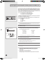
Purging the Indoor Unit
Upon delivery, there may be inert gas inside the indoor unit. Purge the gas
from the indoor unit before connecting the assembly pipe.
Unscrew the caps at the end of each pipe.
Result:
All inert gas exhausts from the indoor unit.
To prevent dirt or foreign substances from getting into the pipes during
installation, do NOT remove the caps completely until you are ready to
connect the pipes.
E-7
AVXWN@@_IM_E_31755_5.08.10.indd 7
2010-5-8 10:34:33
EEV Kit Installation
Preparing for Installation
Concrete
1
Check dimension and installation location.
2
Check installation place.
Insert
Hole in anchor
Hole in plug
By using a pattern sheet, check required installation space.
Suspension bolt(3/8" or M10)-field supply
���
���
Unit : mm
450mm X 200mm or more
(Maintenance Hole)
Maintenance hole must be located on
the ceiling.
���
���
���
���
���
���
��
��
�� ��
���
���
���
���
��
���
���
��
Required maintenance
space
���
Indoor unit pipe
connection
Required
maintenance space
���
Outdoor uint pipe
connection
Required
maintenance space
Drain hole
��
��
���
���
��
���
��
��
���
Required maintenance
space
��
E-8
AVXWN@@_IM_E_31755_5.08.10.indd 8
2010-5-8 10:34:48
Connection of refrigerant piping & Insulation
1
Insert bot anchors, use existing ceiling supports or construct
a suitable support.
Ensure the ceiling is strong enough to support the weight of the indoor
unit. Before hanging the unit, test the strength of each attached suspension bolt.
2
Connect the “IN” refrigerant pipe to the outdoor unit.
3
Connect the “OUT” refrigerant pipe to each indoor unit(A, B and C).
The liquid and gas pipes should not be crossed when piping connection.
4
Insulate the connection piping. A joint part of pipe needs double
thickness of insulation.
5
The EEV kit has to be installed that the user has no access to it. (built-in type)
Nylon band
EEV Kit body
E-9
AVXWN@@_IM_E_31755_5.08.10.indd 9
2010-5-8 10:34:49
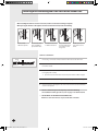
EEV Kit Installation (Continued)
Wiring & Assigning address
A
B
C
Room A
Room B
Another
EEV Kit
Outdoor
unit
1
Connect the AC power cable and communication cable from the outdoor
unit to terminal, then connect the cable to another EEV kit.
2
Connect the AC power cable and communication cable to each indoor unit
(A, B and C).
3
EEV kit address should be set same with connected indoor units main
address.
For Example
When Main address is set as “03” that connected in pipe “A”,
the EEV kit “A” address should be set as “03”.
A
E-10
AVXWN@@_IM_E_31755_5.08.10.indd 10
2010-5-8 10:34:50
Function of Display
The numbers which are displayed on left are the status of indoor unit checking
status through communication with same outdoor unit.
(If it indicates 1, 3 and 7, that means the ADDRESS of indoor unit is set to 1, 3 and 7.)
The numbers which are displayed on right indicate the ADDRESS of SW01/SW02,
SW03/SW04 and SW05/SW06 in sequential. (If it indicates 0, 1 and 2, that means the
SW01/SW02 is set to 0, the SW03/SW04 is set to 1, and the SW05/SW06 is set to 2.)
If the communication error occurs in EEV Kit, the ErC0 message will be shown on
the display alternatively.
KEY function
If you press a KEY on the PCB, the display will show you a step of appropriate
EEV Kit.
KEY No.
Meaning
K1
K2
K3
K4
Step of EEV Kit A
Step of EEV Kit B
Step of EEV Kit C
-
Example
19 (19 x 10 = 190 STEP)
-
Test run
Each indoor unit runs separately to check pipe connection and address setting.
If all units run at the same time, pipe cross connection and address
mismatching cannot be found.
E-11
AVXWN@@_IM_E_31755_5.08.10.indd 11
2010-5-8 10:34:51
Installing and Connecting the Assembly Pipe of the Indoor Unit
Connect indoor and outdoor units with field-supplied copper pipes by means of
flare connections. Use insulated seamless refrigeration grade pipe only, (Cu DHP
type according to ISO1337), degreased and deoxidized, suitable for operating
pressures of at least 4200 kPa and for burst pressure of at least 20700 kPa. Under
no circumstances must sanitary type copper pipe be used.
There are 2 refrigerant pipes of different diameters:
The smaller one is for the liquid refrigerant
The larger one is for the gas refrigerant
A short pipe is already fitted to the air conditioner. You may need to extend the
pipe using the assembly pipe. (optional)
A
B
C
Refrigerant oil
The connection procedure for the refrigerant pipe varies according to the exit
position of the pipe when facing the wall:
Right(A)
Left(B)
Underside(C)
Rear
1
Cut out the appropriate knock-out piece on the rear of the indoor unit unless
you connect the pipe directly from the rear.
2
Smooth the cut edges.
3
Remove the protection caps of the pipes and connect the assembly pipe
to each pipe. Tighten the nuts first with your hands, and then with a torque
wrench, applying the following torque:
Outer Diameter
6.35 mm (1/4")
9.52 mm (3/8")
12.70 mm (1/2")
15.88 mm (5/8")
Torque wrench
Spanner
If you want to shorten or extend pipes, refer to page 13.
Flare nut
Union
Torque (kgf•cm)
145~175
333~407
505~615
630~769
4
Cut off the remaining foam insulation.
5
If necessary, bend the pipe to fit along the bottom of the indoor unit.
Then pull it out through the appropriate hole.
The pipe should not project from the rear of the indoor unit.
The bending radius should be 100 mm or more.
6
Pass the pipe through the hole in the wall.
7
For further details on how to connect to the outdoor unit and purge the air,
refer to page 7.
The pipe will be insulated and fixed permanently into position after
finishing the installation and the gas leak test; refer to page 21 for
further details.
DO NOT WALL UP THE PIPE CONNECTION !
All refrigerant pipe connection must be easy accessible and serviceable.
E-12
AVXWN@@_IM_E_31755_5.08.10.indd 12
2010-5-8 10:34:52
Cutting or Extending the Pipe
1
Make sure that you prepared the required tools.
(pipe cutter, reamer, flaring tool and pipe holder)
2
If you want to shorten the pipe, cut it using a pipe cutter ensuring that the cut
edge remains at 90° with the side of the pipe. There are some
examples of correctly and incorrectly cut edges below.
Oblique
Rough
Burr
3
To prevent a gas leak, remove all burrs at the cut edge of the pipe using
a reamer.
4
Carry out flaring work using flaring tool as shown below.
A
Flaring tool
York
Die
Die
Clutch type
Outer diameter
(mm)
Wing nut type
Flare tool for
R410A clutch type
6.35
9.52
12.70
15.88
A(mm)
Conventional flare tool
Clutch type
Wing nut type
1.0~1.5
1.5~2.0
1.0~1.5
1.5~2.0
1.0~1.5
1.5~2.0
1.0~1.5
1.5~2.0
Check if you flared the pipe correctly. There are some examples of
incorrectly flared pipes below.
Inclined
6
Flare nut
Damaged Surface
Cracked
Uneven Thickness
Align the pipes and tighten the flare nuts first manually and then with a torque
wrench, applying the following torque.
6.35
145~175
8.70~9.10
9.52
333~407
12.80~13.20
12.70
505~615
16.20~16.60
15.88
630~769
19.30~19.70
Flare shape
(mm)
90° ±2°
Outer diameter
Connection
Flare dimension
(mm)
Torque(kgf•cm)
(mm)
45° ± 2°
5
0~0.5
0~0.5
0~0.5
0~0.5
Copper pipe
Copper pipe
R 0.4~0.8
In case of needing brazing, you must work with Nitrogen gas blowing.
E-13
AVXWN@@_IM_E_31755_5.08.10.indd 13
2010-5-8 10:34:53
Installing and Connecting the Drain Hose of the Indoor Unit
When installing the drain hose for the indoor unit, check if condensation draining is adequate.
When passing the drain hose through the 65-mm hole drilled in the wall, check the following:
5cm
less
Ditch
The hose must
NOT slant upwards.
The end of the drain
hose must NOT be
placed under water.
Do NOT bend the hose
in different directions.
Keep a clearance of at
least 5cm between the
end of the hose and
the ground.
Do NOT place the end
of the drain hose in a
hollow.
Drain hose installation:
Shield
Drain hose
Extension drain hose
1
If necessary, connect the 2-meter extension drain hose to the drain hose.
2
If you use the extension drain hose, insulate the inside of the extension drain
hose with a shield.
3
Fit the drain hose into 1 of 2 drain hose holes, then fix the end of the drain
hose tightly with a clamp.
If you don’t use the other drain hose hole, block it with a rubber stopper.
4
Pass the drain hose under the refrigerant pipe, keeping the drain hose tight.
5
Pass the drain hose through the hole in the wall. Check if it slants downwards
as seen in the picture.
The hose will be fixed permanently into position after finishing
the installation and the gas leak test; refer to page 21 for further details.
DO NOT WALL UP THE DRAIN HOSE CONNECTION !
Drain hose connection must be easy accessible and serviceable.
E-14
AVXWN@@_IM_E_31755_5.08.10.indd 14
2010-5-8 10:34:54
Changing Direction of the Drain Hose
You can select the direction of the drain hose, depending on where you want to
install the indoor unit.
1
Detach the rubber cap with the flyer.
Screw hole
2
Screw
Detach the drain hose by pulling it and turning to the left.
Drain hose
3
Insert the drain hose by fixing it into the groove of the drain hose and the
outlet of the drain pan.
4
Attach the rubber cap with a screwdriver by turning it to the right until it fixes
to the end of the groove.
Drain pan outlet
Rubber cap
E-15
AVXWN@@_IM_E_31755_5.08.10.indd 15
2010-5-8 10:34:55
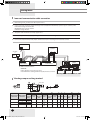
Wiring Work
Power and communication cable connection
1
Before wiring work, you must turn off all power source.
2
Indoor unit power should be supplied through the breaker(ELCB or MCCB+ELB) separated by the outdoor power.
ELCB: Earth Leakage Circuit Breaker
MCCB:Molded Case Circuit Breaker
ELB:Earth Leakage Breaker
3
The power cable should be used only copper wires.
4
Connect the power cable{1(L), 2(N)} among the units within maximum length and communication cable(F1, F2) each.
5
Connect V1, V2(for DC12V) and F3, F4(for communication) when installing the wired remote control.
Outdoor Unit
Wired Remote
Control
220-240V~
or
MCCB+
ELB
ELCB
Indoor Unit 1
Indoor Unit 2
EEV kit
Indoor Unit 3
N
L
N
L
N
L
ELCB : Essential Installation
WARNING :
Power off before connecting any wires;
Indoor PBA will be damaged while V1,V2,F3,F4 short each other.
Indoor Unit 4 Indoor Unit 5 Indoor Unit 6
Ceiling, wall-mounted indoor unit.
Selecting compressed ring terminal
Silver solder
B
D
d1
E
F
L
d2
t
Norminal
Norminal
Standard
Standard
Standard
Standard
dimensions for dimensions for
Allowance
Allowance
Allowance
Allowance
Min. Min. Max. dimension
Min.
dimension
dimension
dimension
cable (mm2)
screw (mm)
(mm)
(mm)
(mm)
(mm)
(mm)
(mm)
(mm)
(mm)
1.5
2.5
4
4
4
4
4
6.6
8
6.6
8.5
4
9.5
±0.2
3.4
±0.2
4.2
±0.2
5.6
+0.3
-0.2
+0.3
-0.2
+0.3
-0.2
1.7
±0.2
4.1
6
16
4.3
2.3
±0.2
6
6
17.5
4.3
3.4
±0.2
6
5
20
4.3
+0.2
0
+0.2
0
+0.2
0
0.7
0.8
0.9
E-16
AVXWN@@_IM_E_31755_5.08.10.indd 16
2010-5-8 10:34:59
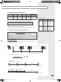
Specification of electronic wire
Power supply
MCCB
Max : 242V
Min : 198V
XA
ELB or ELCB Power cable Earth cable
X A, 30mmA
0.1 sec
2.5mm2
Communication
cable
2.5mm2
0.75~1.5mm2
Rating current
Unit
Decide the capacity of ELCB(or MCCB+ELB) by below formula.
The capacity of ELCB(or MCCB+ELB) X [A] = 1.25 X 1.1 X ∑Ai
X : The capacity of ELCB(or MCCB+ELB).
∑Ai : Sum of Rating currents of each indoor unit.
Refer to each installation manual about the rating current of indoor unit.
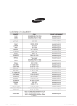
Model
AVXWN 022
028
036
056
071
0.16A
0.16A
0.18A
0.27A
0.30A
NHNH
0.16A
0.16A
0.18A
0.27A
0.30A
022
028
036
056
071
Decide the power cable specification and maximum
length within 10% power drop among indoor units.
Coef×35.6×Lk×ik
n
∑(
1000×Ak
k=1
)<
Rating current
10% of input
voltage[V]
coef: 1.55
Lk : Distance among each indoor unit[m], Ak: Power cable specification[mm2]
ik : Running current of each unit[A]
Example of Installation
- Total power cable length L = 100(m), Running current of each units 1[A]
- Total 10 indoor units were installed
10[A]
9[A]
1[A]
ELCB
Or MCCB+
ELB
Indoor unit2
Indoor unit1
0[m]
10[m]
Indoor unit10
20[m]
100[m]
Apply following equation.
n
∑(
k=1
Coef×35.6×Lk×ik
1000×Ak
)<
10% of input
voltage[V]
Calculation
Installing with 1 sort wire.
2.5[mm2]
2.5[mm2]
-2.2[V]
-2.0[V]
220[V]
············ 2.5[mm2] ············
208.8[V](Within 198V~242V)
it's okay
-(2.2+2.0+1.8+1.5+1.3+1.1+0.9+0.7+0.4+0.2)=-11.2[V]
Installing with 2 different sort wire.
4.0[mm2]
220[V]
4.0[mm2]
-1.4[V]
············ 2.5[mm2] ············
-1.2[V]
-(1.4+1.2+1.8+1.5+1.3+1.1+0.9+0.7+0.4+0.2)=-10.5[V]
209.5[V](Within 198V~242V)
it's okay
E-17
AVXWN@@_IM_E_31755_5.11.10.indd 17
2010-5-11 16:28:10
Wiring Work (Continued)
Select the power cable in accordance with relevant local and national
regulations.
Wire size must comply with local and national code.
For the power cable, use the grade of H07RN-F or H05RN-F materials.
You should connect the power cable into the power cable terminal
and fasten it with a clamp.
The unbalanced power must be maintained within 10% of supply
rating among whole indoor units.
If the power is unbalanced greatly, it may shorten the life of the
condenser. If the unbalanced power is exceeded over 10% of supply
rating, the indoor unit is protected, stopped and the error mode
indicates.
To protect the product from water and possible shock, you should keep
the power cable and the connection cord of the indoor and outdoor
units in the iron pipe.
Connect the power cable to the auxiliary circuit breaker.
An all pole disconnection from the power supply must be incorporated
in the fixed wiring(≥3mm).
You must keep the cable in a protection tube.
Keep distances of 50mm or more between power cable and
communication cable.
Maximum length of power cables are decided within 10% of power
drop. If it exceeds, you must consider another power supplying
method.
The circuit breaker(ELCB or MCCB+ELB) should be considered more
capacity if many indoor units are connected from one breaker.
Use round pressure terminal for connections to the power terminal
block.
For wiring, use the designated power cable and connect it firmly,
then secure to prevent outside pressure being exerted on the terminal
board.
Use an appropriate screwdriver for tightening the terminal screws.
A screwdriver with a small head will strip the head and make proper
tightening impossible.
Over-tightening the terminal screws may break them.
See the table below for tightening torque for the terminal screws.
Tightening torque(kgf•cm)
M4
12.0~14.7
E-18
AVXWN@@_IM_E_31755_5.08.10.indd 18
2010-5-8 10:35:00
Assigning Address to Indoor Unit
1
Before installing the indoor unit, assign an address to the indoor unit
according to the air conditioning system plan.
2
The address of the indoor unit is assigned by adjusting MAIN(SW01, SW02) and
RMC(SW03, SW04) rotary switches.
SW05
SW01
SW02
SW03
SW04
SW06
Cover PCB
SW07
The designs and shape are subject to change according to the model.
Setting Main Address
The MAIN address is for communication between the indoor unit and the
outdoor unit. Therefore, you must set it to operate the air conditioner
properly.
You can set the MAIN address from ‘00’ to ‘99’ by mixing SW01 and SW02.
The MAIN address from ‘00’ to ‘99’ should differ from each other.
Check the indoor unit address on the plan that you are to install and set
the address according to the plan.
Note
You may not need to set main address if you selected Auto
Address Setting from the outdoor unit: see details on the
outdoor unit installation manual.
For Example
When MAIN address is set as "12".
Setting RMC Address
The SW03, SW04 RMC switch is the address setting switch for controlling
the indoor unit with the centralized controller.
You must set the SW03, SW04 and K2 switch when using the centralized
controller.
For Example
When RMC address is set as "12".
SW03
SW04
E-19
AVXWN@@_IM_E_31755_5.08.10.indd 19
2010-5-8 10:35:01
Additional Functions
�� �� �� ��
No.
SW05
����
Function
ON
OFF
K1
External room sensor
Not use
Use
K2
Centralized controller
Not use
Use
K3
-
-
-
K4
-
-
-
K1 OFF
Heating mode : Setting temperature compensation value = 0°C
Thermo OFF Fan OFF
�� �� �� ��
No.
SW06
����
�� ��� ��� ���
ON
OFF
K5
Heating Current Temperature
Compensation
+2°C
+5°C
K6
Filter Time
1,000 hours
2,000 hours
K7
-
-
-
K8
-
-
-
Function
ON
OFF
K9
Indoor Expansion Valve For
Heating Stop
Fix 80 step
0 or 80 step
K10
Wired Remocon Group Master
Not use
Use
K11
External control
Not use
Use
K12
External Control Output
Thermal ON
Operation ON
No.
SW07
����
Function
E-20
AVXWN@@_IM_E_31755_5.08.10.indd 20
2010-5-8 10:35:01
Performing Leak Test & Insulation
Leak test
LEAK TEST WITH NITROGEN (before opening valves)
In order to detect basic refrigerant leaks, before recreating the vacuum and
recirculating the R410A, it’s responsible of installer to pressurize the whole
system with nitrogen (using a pressure regulator) at a pressure above
4.1MPa (gauge).
C
D
LEAK TEST WITH R410A (after opening valves)
Before opening valves, discharge all the nitrogen into the system and
create vacuum. After opening valves check leaks using a leak detector for
refrigerant R410A.
Discharge all the nitrogen to create a vacuum and charge
the system.
Insulation
After checking for gas leaks in the system, insulate the pipe, hose and cables.
Then place the indoor unit on the installation plate.
1
To avoid condensation problems, place heat-resistant polyethylene foam
separately around each refrigerant pipe in the lower part of the indoor unit.
2
Wrap the refrigerant pipe and the drain hose in the rear of the indoor unit with
the absorbent pad.
Wind the pipe and hose three times to the end of the indoor unit with the
absorbent pad. (20mm interval)
3
Wind the pipe, assembly cable and drain hose with insulation tape.
4
Place the bundle (the pipe, assembly cable and drain hose) in the lower part of
the indoor unit carefully so it doesn’t project from the rear of the indoor unit.
5
Hook the indoor unit to the installation plate and move the unit to the right
and left until it is securely in place.
6
Wrap the rest of the pipe with vinyl tape.
7
Attach the pipe to the wall using clamps (optional).
Installation plate
E-21
AVXWN@@_IM_E_31755_5.08.10.indd 21
2010-5-8 10:35:02
Final Check and Trial Operation
To complete the installation, perform the following checks and tests to ensure
that the air conditioner operates correctly.
1
Check the following:
Strength of the installation site
Tightness of pipe connection to detect gas leak
Electric wiring connection
Heat-resistant insulation of the pipe
Drainage
Grounding conductor connection
Correct operation (follow the steps below)
2
Press the
button and check the following:
The indicator on the indoor unit lights up.
The airflow blade opens and the fan gears up for operation.
3
Press any button and check the following:
The appropriate indicator lights up and the air conditioner operates
according to the selected mode or function.
4
Press the
button and check the following:
The airflow blades work properly.
E-22
AVXWN@@_IM_E_31755_5.08.10.indd 22
2010-5-8 10:35:03
Providing Information for User
After finishing the installation of the air conditioner, explain the following to
the user: (refer to appropriate pages in the User’s Manual.)
1
How to start and stop the air conditioner
2
How to select the modes and functions
3
How to adjust the temperature and fan speed
4
How to adjust the airflow direction
5
How to set the timers
6
How to clean and replace the filters
When you complete the installation successfully, hand over the User’s
Manual and this Installation Manual to the user for storage in a handy and
safe place.
E-23
AVXWN@@_IM_E_31755_5.08.10.indd 23
2010-5-8 10:35:04
"EEE Yönetmeliğine Uygundur"
"This EEE is compliant with RoHS"
AVXWN@@_IM_E_31755_5.08.10.indd 24
2010-5-8 10:35:04