1
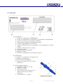
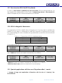
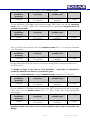
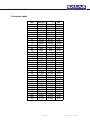
User’s Manual
KALAS Medical, s.r.o.
Slovenských partizánov 1130/50,P.O.BOX 48/A
017 01 Považská Bystrica
SLOVAKIA
Page 1
tel:
fax:
E-mail:
Web:
00421 42 4326907, 4325104
00421 42 4326907
[email protected]; [email protected]
www.kalas.sk
© 2008 Kalas Medical
OB1
This technical appliance will reliably serve its purpose only if used in
accordance with this User’s manual. All guaranties related to the machine
provided by the company Kalas Medical Ltd. will be void if the appliance
shall not be used and maintained in accordance with this User’s manual.
The appliance can be used only by qualified and trained personnel that
have carefully studied and considered this User’s manual, warnings on the
appliance or corresponding documentation and followed all specified
guidelines and instructions.
If this machine is not operating as specified in this User’s manual, we do not
recommend its usage.
Operating personnel are responsible for all injuries or harm to health resulting
from the incorrect use, unauthorised repairs, damage or non-adequate
maintenance performed by other than Kalas Medical Ltd. personnel or
contractual representatives of KALAS Medical Ltd. Považská Bystrica,
Slovakia.
If you need any advice, explanation or any additional information about the
appliance, please contact the commercial representative, or the producer.
Page 2
© 2008 Kalas Medical
WARNING:
Defects of the appliance caused by non-professional use, or not
following the guidelines and instructions mentioned in this User’s manual,
will not be admitted for claim and warranty repair.
The producer is not responsible for damages caused by carelessness.
The producer reserves the right to make changes to the appliance that
will not considerably affect the characteristics of the machine.
Page 3
© 2008 Kalas Medical
Summary
1.
2.
3.
Characteristics and technical specification of the appliance.......................... 5
Safety instruction........................................................................................................ 6
Supplied equipment ................................................................................................. 7
3.1. Basic equipment .................................................................................................... 7
3.2. Accessory equipment – as per separate order ................................................ 8
4. Description of the appliance................................................................................... 8
5. Usage of ventilator .................................................................................................. 10
5.1. Switching ON / OFF the ventilator ..................................................................... 10
5.2. Feeding by external adapter from external power supply ........................... 10
5.3. Reserve power supply - batteries ...................................................................... 11
5.4. Pneumatic – manual mode ............................................................................... 11
5.5. Set up / assembling of the ventilator ................................................................ 12
5.6. Disassembling of ventilator ................................................................................. 14
6. Cleaning and sterilization of ventilator.................................................................... 14
7. Process of starting ventilation ................................................................................... 15
7.1. Control of functions ............................................................................................. 15
7.2. Setting of the ventilator....................................................................................... 16
8. Special modes of ventilation .................................................................................... 18
8.1. Deepened ventilation (Ventilation during spontaneous breathing)........... 18
8.2. Cleaning of airways / Tracheo-bronchial Toilette .......................................... 18
8.3. Inpulsion mode ..................................................................................................... 18
8.4. Expulsion mode .................................................................................................... 18
8.5. Long term ventilation........................................................................................... 19
9. Most common problems............................................................................................ 20
10. HFJV COOKBOOK - Quick guide of OB 1 Paravent parameters set-up .......... 22
10.1. Set-up of basic parameters.............................................................................. 22
10.2. Determination of MV (minute ventilation) and Vt (tidal volume) .............. 23
10.3. Overview for a quick orientation..................................................................... 28
10.4. Applications of HFJV providing for transitional / clear airways .................. 28
10.5. Less standard situations..................................................................................... 28
10.6. Non-standard situations .................................................................................... 29
10.7. Non-invasive HFJV-M (HFJV by Mask)............................................................. 30
10.8. HFJV in Magnetic Resonance.......................................................................... 30
10.9. Special applications with the use of Expulsion effect / mode ................... 30
10.10. Special applications in tracheo-bronchial surgery .................................... 32
10.11. Special applications in otolaryngologic surgery......................................... 32
Page 4
© 2008 Kalas Medical
1. Characteristics and technical specification of the
appliance
The OB1 Paravent PATe is an electronically-controlled high frequency jet ventilator
with changeable frequency of 20, 40, 120, 180 c/min (switch FREQUENCY - position
A.1) optional time ratio inspiration time / expiration time 1:2, 1:1 and 2:1 (switch TIME
RATIO - position A.2) and adjustable insufflation pressure 0 - 300 kPa (switch INSUF.
PRESS. – position A.11) which is monitored (position A.4). The insufflation pressure
varies with the change of insufflation nozzles of the multi-nozzle jet injector (MNJI) to
ventilating pressure levels according to the chosen nozzle independently of the size
of MNJI used. Ventilated pressure is monitored on the manometer (position E.1) on
the top cover of the machine either in the whole breathing cycle (frequency of 20,
40 c/min) or its peak pressure at the end of inspiration (frequency of 120, 180 c/min).
Supply pressure
400 kPa ± 100 kPa
Flow of source of
pressure
min. 50 l/min.
Power supply
A. 12V DC 100mA - for mains feed external adapter 230V
AC / 12V DC (SZ 12/2/100)
B. Reserve - 4x NiMH battery size AA (ensures not less than
8 working hours when fully charged)
C. pneumatic
Frequency
optional :
Time ratio Ti : Te
optional : 1:2, 1:1, 2:1 ±5% (if 2:1 and 120 or 180 c/min active,
the expiration jet is turned on)
Change of insufflation
pressure
0 – 300 kPa / min.; monitored by pressure gauge on front
panel
Max.ventilation power
according to insufflation pressure
For insufflation pressure 160 kPa - dýza č.I
- nozzle n.I
max. 2.5 kPa
- nozzle n. II
max. 4.5 kPa
- nozzle n. III
max. 7.0 kPa
-expiration nozzle max. 4.0 kPa
Pressure limit
Pressure gauge of
ventilation
Dimensions W, H, L
20, 40, 120, 180 c/min ± 5 %
max. 2.5 kPa
fixed : 5 kPa ± 5 % (static), max. reaction time 120 ms
A. Whole process of breathing cycle (PAW) for frequencies
20 and 40 c/min.
B. The highest pressure at the end of inspiration (PIP) for
frequency of 120 and 180 c/min
235 x 100 x 250 mm
Page 5
© 2008 Kalas Medical
Weight
4.3 kg
Noise Level
max. 74 dB
Working conditions
temperature
humidity
–10 °C to + 40 °C
max. 80 %
Classification
1. Type of protection against electricity accident:
a) external adapter 230V AC / 12V DC (SZ 12/2/100 from
Enco) is class II
b) when mains feeding by external adapter 230V AC / 12V DC
(SZ 12/2/100 from Enco) the whole machine is
class II B as per ČSN EN 60601-1
c) when using NiMH batteries as a reserve power supply, the
machine is using the internal power supply
2. Level of protection against electricity accident :
machine is type B as per ČSN EN 60601-1
3. Level of protection against harmful penetration of water:
External adapter 230V AC / 12V DC (SZ 12/2/100 from
Enco) and the machine itself are protected against
leaking water (IPX1) as per ČSN EN 60601-1
4. Working mode :
machine can be used in permanent operation
5. Protection against the danger of inflammation of
flammable
anaesthetic mixtures :
The machine must not be used in environment where are
flammable anaesthetic mixtures as per ČSN EN 60601-1.
For ventilation in the field or during transportation, a source of compressed oxygen
(pressure cylinder with the capacity 2, 5, or 10 L) equipped with a cylinder pressure
regulator with a quick coupler which is set up to outlet overpressure 400 kPa ± 100 kPa is
required.
2. Safety instruction
•
•
•
•
•
This user’s manual is an inseparable part of the appliance.
Before using the appliance read carefully this manual.
Respect all warnings.
Follow the instructions.
Service and reparation of the appliance can be executed only by authorized
persons. Original replacement parts must be used while repairing. If original
replacement parts are not used the appliance can be damaged and its correct
operation cannot be ensured.
Page 6
© 2008 Kalas Medical
3. Supplied equipment
3.1. Basic equipment
Make sure the packing includes following equipment:
Ordering
Number
No.
of
units
PVF 046
2x
PVF 075-068
set
3x
one-way valve for ventilating with pure
oxygen FiO2 ≅ 0,95
PVF 031.1
5x
set of extensions for ventilation with the
mask (size 5, 8, 10)
(reduction: MNJI5-mask ; MNJI8-mask;
MNJI0-mask)
PVF 031.2
5x
T- set for expulsion mode
PVF 035
1x
external adapter 230V AC / 12V DC
MES30AMED
1x
recharge cable for emergency vehicles
PVK 047
1x
-
1x
-
-
1x
-
-
1x
-
Spare part
Set of catheters PATe
(length cca 1,5m , standard set 3pcs of
cathethers)
set of MNJIs (multi-nozzle jet injector)
(8 tprm MNJI 3; 4; 5; 6; 7; 8; 9; 0 set )
back-up power reserve ( 4 pcs NiMH type
AA )
NiMH battery charger for recharging backup reserve
user’s manual
Page 7
PHOTO
© 2008 Kalas Medical
3.2. Accessory equipment – as per separate order
As per the
specifications of
customer
extensions for rigid bronchoscope
Set of adjusted catheters
(lenght 10m, set of 2pcs of catheters from
non-magnetic material)
Spare insufflation valve
-
PVF 046.1
PVF 018
4. Description of the appliance
A. Front panel
Page 8
© 2008 Kalas Medical
B. Rear panel
A) Front panel
1. Switch for adjustment of FREQUENCY
2. Switch for adjustment of TIME RATIO of inspiration and expiration
3. Switch for manual / pneumatic ventilation
4. Manometer / gauge of insufflation pressure
5. Luminous LED indicator of batteries
6. Luminous LED indicator for connection of the appliance to mains
supply
7. Luminous LED indicator for alarm
8. Inspiration valve
9. Slot for measuring catheter
10. Expiration valve
11. Switch for adjustment of insufflation pressure
B) Rear panel
12. Valve for connection of oxygen hose
13. Battery compartment
14. Slot for external adapter
15. Switch for switch ON / OFF of the
appliance
C) Multi nozzle jet injector
1. Inspiration nozzles n. I, II a III
2. Expiration nozzle
3. Measuring nozzle
4. Connection for ET cannula or for
mask connection by mask’s
extension
5. Connection for T – piece
Page 9
© 2008 Kalas Medical
D) Set of catheters
1. Inspiration catheter – color: red
2. Expiration catheter – color:
green
3. Measuring catheter
4. LUER cone of inspiration
catheter
5. LUER cone of expiration
catheter
6. RECORD cone of measuring
catheter
E) Top cover
1. Manometer / gauge for the
Paw pressure
5. Usage of ventilator
5.1. Switching ON / OFF the ventilator
To switch ON the ventilator put the switch for switch ON / OFF n. B.15 into the position
๏.
To switch OFF the ventilator put the switch for switch ON / OFF n. B.15 into the
position O.
5.2. Feeding by external adapter from external power supply
Electrical supply of the appliance is through the external adapter 220 V AC / 12
V DC.
Plug the external adapter 12 V DC to the external power supply. The green LED on
the adapter will light up. Plug the connector of external adapter to the slot (position
B.14) on the appliance. On the front panel the green LED (position A.6) will light up
to indicate external power supply.
In this case the power supply is the electrical network even if the batteries are
placed in the battery compartment.
It is possible to keep the external adapter plugged into external power supply for
maintenance of NiMH battery capacity if they are placed in the battery
compartment. This state is indicated by green LED in field BATT. (position A.6).
Using any other adapter than the one supplied by the manufacturer of the product
is not recommended.
Page 10
© 2008 Kalas Medical
5.3. Reserve power supply - batteries
Electrical Reserve is provided by four NiMH batteries of size AA (position B.13). When
fully charged, the reserve enables the ventilator to operate for at least 8 hours. The
basic equipment of the ventilator includes AA sized, NiMH battery charger to be
used to keep the reserve in optimum state (the battery charger manual is enclosed
in its package). The capacity of batteries plugged in the ventilator is maintained
against self-discharging by a small electric current as long as the ventilator is
plugged to external power supply unit. This state is indicated by green LED in field
BATT. (position A.5).
Regular “dry” or alkaline batteries of size AA are not to be used as reserve. NiCd or
NiMH batteries of size AA with the capacity at least 500mAh must be used.
Place charged batteries into the slot marked as BATTERIES (position B.13) in the way it
is indicated on the top of the slot.
If the ventilator is not connected to the external power supply by the adapter, the
green LED will come on (position A.6) when the batteries are charged. If the red LED
(position A.5) comes on the batteries are not sufficiently charged and it is necessary
to charge them according to the user’s manual in enclosed charger.
NiMH batteries need to be kept in a good condition with help of a charger from the
basic equipment as written in the enclosed manual of the charger. Once a month
have the batteries recharged in the charger using the discharging mode. The period
of usage recommended by the ventilator manufacturer is 2 years. New spare NiMH
batteries can be bought from the manufacturer, or their authorised agent.
If the reserve is unplugged from the machine, this is indicated (with the ventilator
plugged into the mains feed and turned on) by red LED (position A.5) in the field
BATT.
Lower voltage of back-up power reserve is indicated by red flashing LED (position
A.5) in the field BATT once in two seconds when the machine is plugged to mains
feed and in case of running the ventilator from the reserve it is also indicated by the
acoustic alarm (0.5 second long beep 1x in 10 seconds).
Insufficient voltage of back-up power reserve is indicated by red flashing LED
(position A.5) in the field BATT twice in a second when the machine is plugged to
mains feed and in case of running the ventilator from the reserve it is also indicated
by an acoustic alarm (2x in a second together with visual alarm) and by stopping
the machine. In this case, the manual controls of inspiration and expiration time by
the switch MANUAL can be used (position A.3).
5.4. Pneumatic – manual mode
If necessary it is possible to use manual operation of inspiration and expiration time
by switch MANUAL (position A.3). By pushing this switch you define the time of the
inspiration and while it’s released the expiration is proceeding. Repeat the manual
ventilation as needed.
In pneumatic / manual mode it is imperative the ventilator is connected to the
oxygen or compressed air source.
Page 11
© 2008 Kalas Medical
5.5. Set up / assembling of the ventilator
A.) Valve connection:
1) Plug inspiration insufflation valve to the slot marked INSP in red field (position
A.8) and secure it by tightening safety bolts
2) Plug expiration insufflation valve to the slot marked EXP in green field
(position A.10) and secure it by tightening safety bolts
These valves are not exchangeable. In the case of exchange of bolts, these can’t be
fastened, which prevents the exchange and ensures the proper fit of valves and
proper function of the appliance. When unpacking the ventilator from original pack
the inspiration and expiration valves are already installed.
B.) Connection of set of catheters to ventilator :
1) Connect inspiration insufflation catheter to inspiration insufflation valve (red to
red) by quick coupler marked red (n. D.1 to position A.8). The Inspiration
insufflation catheter ends by cone LUER and lavage valve.
2) Then connect expiration insufflation catheter to expiration insufflation valve
(green to green) by quick coupler marked green (n. D.2 to position A.10). The
Expiration insufflation catheter ends by curved connector with cone LUER.
3) Connect measuring catheter to connector marked MEAS. CATH. (n. D.3 to
position A.3) by quick coupler marked grey. The measuring catheter ends
with a connector RECORD
The exchange of connections of catheters to insufflation valves is not possible.
C.) Connection of set of catheters to MNJI :
1) Choose MNJI by the number which symbolises the diameter of its cylindrical
cavity (tolerance +-0.5mm) for pre-chosen endo-tracheal tube with the same
diameter (e.g. for tracheal tube 3,5 - MNJI No. 3 or 4) and measuring
connector of the same size.
2) Using LUER cone, connect inspiration insufflation catheter with lavage valve
to the hole of inspiration nozzle of chosen MNJI marked by roman number I (n.
D.4 to C.1). While choosing the size of inspiration nozzle, see also the
Cookbook OB1 Paravent PATe.
3) Expiration insufflation catheter with curved connector LUER is to be
connected to the hole of expiration nozzle of MNJI (n. D.5 to C.2) (see picture
n. 1).
4) Connect measuring catheter by RECORD cone to the hole of measuring
connector (n. D.6 to C.3) (see pic. 1).
Page 12
© 2008 Kalas Medical
Picture n. 1 - Connection of set of catheters to
MNJI
D.) Connection of MNJI to the mask:
1) To the connection n. C.4 of the MNJI connected to set of
catheters as described in part 5.5.C.), connect the
extension / reduction for the ventilation with mask. The size
of the extension / reduction must fit with the size of mask
(see picture n. 2).
2) Connect the mask to the extension / reduction (see
picture n. 2).
Picture n.2 – Connection of MNJI to the mask
E.) Connection of ventilator to the source of oxygen / compressed air :
Connect the ventilator by quick coupler on the oxygen hose (position B.12) to the
source of oxygen or compressed air (central distribution or oxygen bottle with
reduction and quick coupler).
Page 13
© 2008 Kalas Medical
5.6. Disassembling of ventilator
After finishing ventilation and the ventilator is disconnected from the compressed
oxygen:
1) Disconnect inspiration insufflation catheter by quick coupler (n. D.1 from
position A.8)
2) Disconnect expiration insufflation catheter by quick coupler (n. D.2 from
position A.10)
3) Disconnect measuring catheter by quick coupler (n. D.1 from position A.9)
4) Unscrew nuts to release and pull out insufflation valves (position A.8 and A.10)
for their sterilization
5) It is possible to leave external adapter permanently connected to the
machine to conserve charged NiMH batteries that are kept in the ventilator this mode is indicated by a green LED lit on in the BATT field (position A.6). See
the part 5.3.
6. Cleaning and sterilization of ventilator
MNJI's, one-way valves and T pieces are packaged in an ISO certified sterile
environment, and remain sterile until opened. These pieces cannot be re-sterilised
once open, and are designed for single-patient usage only, as re-sterilisation may
alter the physical properties and thus have an effect on airflow through the device.
Possible modes of cleaning and sterilization of individual parts of ventilator:
- insufflation valves - steam sterilisation at the temperature of 120o C, number of
sterilization cycles is set by the durability of material
- the set of catheters - ethylenoxid sterilisation, number of sterilization cycles is set
by the durability of material (min. 50-times)
- after the usage of lavage valve, it is necessary to disassemble and disinfect the
lavage valve, clean it with an antivirus active cleaner, wash it in distilled water
and dry it before proceeding the sterilisation
- set of extensions for ventilation with the face mask – made for one time use only
- the set of extensions for rigid bronchoscope - ethylenoxid sterilisation, number of
sterilization cycles is set by the durability of material (min. 50-times)
- MNJI, one way valve, T set – single patient use only; attempts to sterilise may
compromise the physical shape and therefore resulting flow of air through the
MNJI, and is not safe
- cover of ventilator - can be cleaned using any possible cleaner with the
exception of abrasive ones. In case of staining the cover with biological material
(e.g. blood, etc.) disinfect it by use of an antivirus active cleaner.
Page 14
© 2008 Kalas Medical
7. Process of starting ventilation
7.1. Control of functions
1) Set up the ventilator as described in section 5.5.
2) Set the required insufflation pressure by turning the insufflation pressure switch
(position A.11). The actual value is monitored and shown on the manometer
(position A.4).
3) Switch on the ventilator (part 5.1.)
This activates the ventilator and checks its ability to work including the check of
reserve power supply. It is accompanied by 3x the sound of the acoustic alarm and
flash of visual alarms. After this, the machine will start working. This can be
recognised by frequent exhaust from the cone LUER of inspiration insufflation
catheter in frequency chosen on the switch FREQUENCY. Time ratio of Ti / Te is given
by the switch TIME RATIO.
The expiration insufflation valve is automatically activated when the TIME RATIO is 2:1
and the Frequency is either 120 or 180 c/min. This can be recognised by frequent
exhaust from the LUER cone of curved connector of expiration insufflation catheter.
At this time the operating personnel should check the amount of oxygen in the
pressure bottle which cannot be less than 12 Mpa.
Control of the peak pressure (pressure limit):
1) Choose MNJI n.3
2) Connect the inspiration insufflation catheter with lavage valve through LUER
cone into the hole of inspiration nozzle marked by the roman number III (n.D.4
to C.1)
3) Connect the expiration insufflation catheter with the curved connector LUER
to the hole of expiration nozzle of MNJI (n.D.5 to C.2)
4) Connect the measuring catheter through RECORD cone into the hole of
measuring catheter of MNJI (n.D.6 to C.3)
5) Connect the ventilator to the source of oxygen / compressed air
6) Set the insufflation pressure to cca 90 kPa (position A.11)
7) Set the frequency of ventilation to 40 c/min (position A.1)
8) Switch on the ventilator (part 5.1.)
9) Close the distal end of MNJI and slowly increase the insufflation pressure up to
the activation of alarm of peak pressure
The output pressure of the ventilator is monitored on the manometer that is located
on the top cover of the appliance. Alarm of peak pressure of the appliance is
activated when the output pressure exceeds the pressure of 5 kPa ±0.5 kPa (airway
pressure measured). Together with this alarm signalization, the inspiration (resp.
active expiration) is disconnected up to the next breathing cycle.
Page 15
© 2008 Kalas Medical
7.2. Setting of the ventilator
To make high-frequency jet ventilation successful, one has to choose adequate
intubation including the choice of endo-tracheal tube corresponding to age and
weight of patient.
1) Connect the ventilator assembled according to the part 5.5. to the source of
oxygen / compressed air and switch it on (part 5.1.).
2) Check the level of the insufflation pressure on pressure gauge on front panel
(position A.4) and set its required value by switch n.A.11.
3) Set the required frequency by switch n A.1.
4) Set the required time ration by switch n. A.2.
5) Choose an MNJI by the number which symbolises the diameter of its
cylindrical cavity (toleration +-0.5mm) for pre-chosen endo-tracheal tube
with the same diameter (e.g. for tracheal tube 3.5 - MNJI No. 3 or 4) and
measuring connector of the same size.
6) Connect distal cone ending of MNJI to endo-tracheal tube of patient (n.
C.4).
7) Ventilation pressure can be seen on the gauge on the top cover of the
ventilator either during the whole time (frequency 20, 40 c/min) or at its peak
level at the end of inspiration (frequency 120, 180 c/min) (position E.1).
8) Check breathing movements of the breast of patient or auscultation which
are the signs of working ventilator. Furthermore, you can check the level of
ventilation by common clinical signs such as complexion colour, mucous
colour, etc. and evaluate the sufficiency of ventilation.
In case of insufficient level of ventilation (small breathing movements, lasting
cyanosis, etc.) switch inspiration insufflation catheter by LUER cone from inspiration
nozzle marked as number I to next inspiration nozzle marked as number II which
increases the level of ventilation and check up the patient again.
In case of still not having high enough level of ventilation (small breathing
movements, lasting cyanosis, etc.) switch inspiration insufflation catheter by LUER
cone from inspiration nozzle marked as number II to the next inspiration nozzle
marked as number III which again increases the level of ventilation and check the
patient again.
You can fine tune the power of ventilation e.g. according to control of blood gases
by changing insufflation pressure (meant as ±) by switch INSUF. PRESS. (position A.11)
while checking the manometer on the top cover of the machine (position A.4).
Having higher level of ventilation power may lead to higher inspiration pressures over
the limit of 5 kPa which starts acoustic and visual alarm (red LED of front panel in the
field ALARM – position A.7) and temporary limitation of inspiration.
Using inspiration nozzle I or II, the concentration of oxygen in the mixture of inspiration
gases varies from 0.5 to 0.7 depending on topical resistance of patient’s airways and
amount of torn-down surrounding air. The higher the resistance of lungs, the higher
the concentration of oxygen in the inspiration mixture is.
To ventilate with pure oxygen, put the one-way valve on the proximal end of MNJI
(position D.5) and connect the inspiration insufflation catheter to the hole of
inspiration nozzle marked one number higher. The connection of one-way valve will
disable to tear down the air from the surrounding atmospheric space. For this reason,
during the use of the one-way valve it is highly important to keep checking the
pressure gauge on the reducing valve of the pressure oxygen bottle (cannot fall
below 12 Mpa) and to keep checking the functioning of ventilator.
Page 16
© 2008 Kalas Medical
For other setting of the ventilator see the Cookbook for OB1 Paravent PATe.
Page 17
© 2008 Kalas Medical
8. Special modes of ventilation
8.1. Deepened ventilation (Ventilation during spontaneous breathing)
The construction of the MNJI and the principle of high-frequency jet ventilation
enables an easy and effective way of deepened ventilation even in cases when the
relaxation or other lowering of spontaneous breathing activity of patient is not
recommended. This is so called superposition of HFJV on spontaneous breathing,
when spontaneous inspiration is discontinuely deepened by the ventilator and the
work of ventilator in spontaneous expiration is discontinuely interrupted and slowed
down.
For this type of ventilation, it is recommended to choose the inspiration nozzle
numbered I or II. For this type of ventilation, it is absolutely unacceptable to use a
one-way valve.
8.2. Cleaning of airways / Tracheo-bronchial Toilette
The construction of the MNJI, insufflation system including lavage valve and the
principle of high-frequency jet ventilation enables drawing out from tracheobronchial areas without stopping the ventilation of the patient. In this case, the
sucking catheter is plugged through the proximal end of MNJI into endo-tracheal
tube and further according to the needs, at either permanent or interrupted
drawing out. It is recommended to set higher ventilation power or overplacing
inspiration insufflation catheter with the LUER cone in MNJI to the hole of one
number higher nozzle (from I to II or from II to III) or to set higher insufflation pressure
because the sucking catheter limits the ventilation power when having set higher
ventilation frequencies (especially 120 and 180 c/min) for longer period of time. At
the end of sucking (drawing out), you have to replace the inspiration insufflation
catheter with the LUER cone to the hole of initial inspiration nozzle and possibly
adjust the insufflation pressure.
8.3. Impulsion mode
To lavage the airways, connect the syringe with lavage mixture to the hole in lavage
valve with the cone LUER. For the instillation of the mixture into the airways choose
impulsion mode with the time ratio 1:2 on the switch TIME RATIO. Push the mixture to
inspiration insufflation catheter by slow, constant pressure on the injection plunger.
From there it is by a pressure in inspiration insufflation catheter through the MNJI jet
and by high kinetic energy of a stream of oxygen sprayed to the airways in a form of
aerosol. During this operation, we recommend setting slightly higher ventilation
power by increasing the insufflation pressure by about 20%.
8.4. Expulsion mode
Expulsion mode is initiated by changing the I:E ratio to 2:1 on the switch TIME RATIO.
In this instance with a frequency of 120 or 180 c/min, the expiration nozzle is
automatically activated to limit dynamic positive end-expiratory pressure (PEEP) in
the airways. In this mode, it is useful to deflate the cuff of the endo-tracheal tube to
keep released phlegm from cumulating between the wall of trachea and the wall of
endo-tracheal tube. Released phlegm then moves out into mouth from where it can
be easily sucked out. The sucking can also be performed inside endo-tracheal tube
Page 18
© 2008 Kalas Medical
and airways during the ventilation. In this mode, it is not recommended to use nozzle
number I because its power is not balanced with the expiration nozzle.
In this mode, it is possible for the released phlegm to be splashed by expulsion effect
from the proximal ending of MNJI which could contaminate surroundings. For this
reason, part of accessory equipment contains a T-set that serves the purpose of
elimination of possible contamination. The T piece of the T-set is to be connected by
the cone F15 to the cone M15 on the proximal ending of MTG. The expiration tubing
from the T-set is to be connected to the cone M22. Max. length of tubing is 1.2 m.
Aerosol is captured on the walls of tube that can lead to dust-bin or can be simply
covered by a sheet of linen.
It is essential that the distal end of the hose is not closed.
You must ensure the prevention of tube choking as this is the only way by which
expiration can be realized.
The T-set is a disposable material for single patient use only!
8.5. Long term ventilation
Application in time periods of 1-2 hours will not cause any significant problems even
without any humidification. The issue of humidification and heating of breathing
mixture can be partly solved by humidification and heating of that part of breathing
mixture that is torn down from the atmosphere. For this purpose, you must use the “T”
piece connector.
The Valve T connector serves o the purpose of isolating the part of air injected by
the jet system in inspiration from expired gas mixtures from patient during expiration.
This feature allows the effective set-up of the injected part of inspiration (from the
point of view of humidification and oxygenation) and the elimination of
contamination of the surrounding space of patient by infectious aerosol originated
in such ventilation.
The shoulder "A" (see pic. below) supplies atmospheric air torn down by the jet
system in inspiration mode. It has an outside cone 22M.
For the enhancement of humidification of breathing mixture, it is possible to connect
this shoulder with a 22 mm tube to the output of humidifier. The input of humidifier is
connected to the atmosphere.
Further, it is possible to thin the oxygenation of the atmosphere torn-down gas
mixture by the external mixer of air and oxygen. In this case it is necessary to set-up
the flow of this gas mixture between 15 and 25 l/min, or alternatively including a
reserve bag of volume 0.5 to 2.0 L into this branch.
Such adjustments of the breathing mixture allow longer-term high-frequency jet
ventilation and require relatively large experience with this type of ventilation.
Therefore, for this application we recommend consultation with the producer or an
expert clinical site that is knowledgeable in this topic.
The shoulder "B" serves the purpose of connecting to Multi-Nozzle Jet Injector (MNJI)
of the jet ventilation system. It has a inward cone 15F. This cone is connected directly
to the corresponding cone 15M at the end of MNJI.
Page 19
© 2008 Kalas Medical
The shoulder "C" serves the purpose of removing the expired mixture from patient. It
has an outward cone of 22mm. It is possible to connect it to a 22mm tube of max.
length 1.2 m. The ending of tube shall be placed inside the container where the
potential infectious aerosol originated in the ventilation can be captured (semisealed container).
It is essential that the ending of this tube, alternatively the ending of the shoulder "C"
will NOT BE CLOSED !
Valve T connector is for single-patient use only, the Supplier does not guarantee its
function after the re-sterilisation!
It is essential to connect the T connector as shown below so that the shoulders "A"
and "C" are NOT INTERCHANGED. For the correct connection, the pointers show the
direction of flow of gas through the T-set.
9. Most common problems
1) Disconnection of LUER connector on inspiration insufflation catheter from MNJI
when insufficiently fixed - sudden loss of ventilation power and loud hiss and at the
same time, the alarm of non-ventilation is activated.
SOLUTION: adequate connection of inspiration insufflation catheter with LUER cone
connection, respiration in the hole of chosen nozzle.
2) Choking of inspiration nozzle in MNJI – related mostly to MNJIs with small diameter
(that is 3 and 4). It is recognized by low ventilation power mainly in the connection of
insufflation catheter to the nozzle I.
SOLUTION: wash out the particular inspiration nozzle of MNJI by physiological solution
or by water from syringe or having changed the whole MNJI. Insertion of any metal
object (metal rod, syringe needle, etc.) is NOT recomended.
3) Choking of the measuring catheter or the measuring connector – recognized
through the unjustifiable disconnection or cancellation of ventilation and triggering
of the alarm even when not connected to patient
Page 20
© 2008 Kalas Medical
SOLUTION: clean the measuring catheter and/or the measuring connector
4) With discharge of static electric current (e.g. after the physical contact by
operating personnel), it is possible for the appliance after the discharge to signal
some of the alarm states. After the electrical interference has ended, the alarms will
stop and the appliance will function as normal.
Page 21
© 2008 Kalas Medical
10. HFJV COOKBOOK - Quick guide of OB1 Paravent
parameters set-up
10.1. Set-up of basic parameters
In principle, the set-up of basic flow and pressure parameters is defined by the
construction of the MNJI (Multi-Nozzle Jet Injector).
In the case where ET (endo-tracheal) or TT (tracheostomic) cannula with adapted
MNJI corresponding to patient’s weight is used, the contemplated pressure-flow
parameters are pre-set by the technical construction solution of ’nozzle receiving
channel’ (MNJI – ET or TT cannula) so that the requested (anticipated) level of gas
exchange in lungs can be achieved. Basic Insufflation pressure is Pin = 150 ± 5% kPa.
Ventilation is performed with unsealed ET or TT cannula – seal (cuff) on ET cannula is
not inflated. Basic Frequency of ventilation = 120 c/min.
Mean Pgmax (maximal generator pressure) for Pin = 150 kPa connected to:
Nozzle I
Nozzle II
Nozzle III
2.0 kPa ± 20%
3.5 kPa ± 20%
5.5 kPa ± 20%
This overview is applicable to all sizes of MNJI which provide comparable Ventilatory
performance (it is a static pressure when the outflow-end of MNJI is closed).
Pgmax (maximal generator pressure) for maximal allowable Pin = 300 kPa for all sizes
of MNJI connected to:
Nozzle I
Nozzle II
Nozzle III
4.0 kPa ±20%
7.1 kPa ± 20%
10.2 kPa ± 20%
Typical course of pressure curve of MNJI no. 8 connected in nozzle II with Pin = 150
kPa (blue curve, for comparison: linear regression – black line)
Page 22
© 2008 Kalas Medical
Q in (l/min)
MGT 8/2 -150kPa
250,00
200,00
150,00
Pin
Qmax
Lineární (Qmax)
100,00
50,00
0,00
0,00
0,50
1,00
1,50
2,00
2,50
3,00
3,50
4,00
Pg max (kPa)
According to the medical norm, pressure higher than 10 kPa is considered
destructive to lung parenchyma and shall not be used.
Because the MNJI is constructed in such a way that it can generate the maximal
static pressure Pgmax = 10 kPa, it follows from the physical principle that in open
system of uncuffed ET cannula the pressure limit (Pt) of 10 kPa cannot be exceeded
(Pt – tracheal pressure measured in dynamic mode on experimental animals was for
Pin = 300 kPa in the range 7 – 8.5 kPa, that can be considered as safe from the point
of view of barotrauma).
Furthermore, Pin over 250-280 kPa is strongly discouraged. The second degree of
protection is “total stop”, i.e. pressure guarding and limiting by the ventilator.
10.2. Determination of MV (minute ventilation) and Vt (tidal volume)
For the determination of MV (minute ventilation) and Vt (tidal volume) based on
frequency and other parameters, please use the attached Brychta’s Ventilation
Equation:
Ventilation
equation.xls
Model of tidal volume Vt / minute ventilation MV in HFJV:
1. In HFJV applications, the un-cuffed ET cannula normally used has a different
(i.e. smaller) diameter from the diameter of the trachea; this constitutes
a space for gas leakage during inspiration (mainly) as well as during
expiration. This space also creates a certain small resistance (Ru) for leaking
gas. In smaller patients (children, newborns), the leakage is smaller
considering the anatomy of trachea and it’s mucous.
2. If the MNJI together with a constant pressure generator connected to circuit
load (lungs) constitute the source of exponentially digressive flow, then
a generated volume VTg is the integral of flow (Qg) in time Ti.
Page 23
© 2008 Kalas Medical
3. A part of the volume generated by MNJI is leaking through Ru (leakage) into
the atmosphere and so is VTd delivered into lungs lower than VTg.
4. Multi-nozzle jet injectors (MNJI) are designed and constructed with a large
reserve and principally constitute the pressure generators capable to
compensate for large leakage, whereas Pg (generator pressure) is not
decreasing.
5. The resulting volume flowing into lungs is thus dependent on the mechanical
properties of lungs (Raw and Cst) (Therefore, HFJV is contraindicated in the
cases of high resistance, e.g. severe asthma).
Pin
MNJI
Qg, Pg max, VTg
ET tube
Cuff deflated
Leakage ( X% from VTg)
VT delivered
to lung
Pneumatic model of lungs (per ISO norm) for individual size categories (defined by
the flow of ET cannula) in Tab.1:
Model
C
C
(l/kPa)
50
25
10
3
1
0.50
0.25
0.10
0.03
0.01
R
Rt
Rsum
(kPa/l/s) (kPa/l/s) (kPa/l/s)
0.20
0.35
1.00
5.00
10.00
0.4
0.5
1.0
2.0
2.7
0.6
0.85
2.0
7.0
12.7
Q (i/e)
(l/s)
Tau
(sek)
ETCannula
(mm)
2.00
1.00
0.50
0.075
0.05
0.300
0.212
0.200
0.210
0.127
8-9
6-7
5
3-4
2.5
Using this model, calculation of VT generation was realized at a frequency 120
c/min. and an insufflation pressure Pin = 140 -150 kPa with the use of corresponding
MNJI to ET cannula (3 – 9 mm) on nozzle no. II with Ti:Te = 1:1.
Orientation average values of VTg for the application of MNJI from 3 to 9 in
corresponding models listed in Tab.1 are listed in Tab.2:
ET-Cannula
(mm)
VTg
with Pg=3.3 kPa
8-9
6-7
5
0.334
0.276
0.110
Page 24
© 2008 Kalas Medical
3-4
2.5
0.033
0.018
During the application of HFJV with uncuffed cannula there may be leakage along
ET cannula, with decreased VT delivered into lungs. After the correction for leakage,
VTd and MV is roughly as follows in Tab.3:
ET-Cannula
(mm)
Leakage
%
VT delivered
with
leakage
MV with
leakage
calculated
8-9
6-7
5
3-4
2.5
45
40
35
30
20
0.183
0.166
0.071
0.023
0.014
22.06
19.92
8.58
2.82
1.79
Minute ventilation (MV) calculated for f = 120 b/min is in comparison to the
measured MV in “normal” lungs (Cst and Raw) within the range of cca ± 20%.
This calculation is only orientational, because the parameters of patient lung
mechanics can significantly influence the gas exchange, whereas the correction of
required energy (Pin), while monitoring Paw, and the clinical indications of patient
are always determined by the healthcare practitioner.
Page 25
© 2008 Kalas Medical
Orientational values of Minute Ventilation and Tidal Volume for corresponding
MNJI with adjusted insufflation pressure (Pin)
The tables below show measured values of MV and Vt with and without leakage for
corresponding MNJI on the nozzle II, with frequency 120 bpm, Ti:Te = 1:1, for adjusted
Pin (range 100 – 300 kPa) measured on a laboratory measuring device with the
accuracy of measurement ±1.5 % on “normal” lungs (in terms of Cst and Raw)
intubated with appropriate endo-tracheal tube with uncuffed seal (with normal
leakage around the cuff):
MNJI
Pin (kPa)
Pgmax (kPa)
Qgmax (L)
VT max (L)
VT actual w/o leakage
VT actual with leakage
MV actual with leakage
3 / Nozzle II
100
150
2.55
3.70
14.00
18.00
0.06
0.08
0.02
0.03
0.01
0.02
1.56
2.00
200
4.80
21.00
0.09
0.04
0.02
2.33
300
7.30
25.00
0.10
0.04
0.02
2.78
MNJI
Pin (kPa)
Pgmax (kPa)
Qgmax (L)
VT max (L)
VT actual w/o leakage
VT actual with leakage
MV actual with leakage
4 / Nozzle II
100
150
2.55
3.70
38.00
45.00
0.16
0.19
0.06
0.08
0.04
0.04
4.22
5.00
200
4.80
53.00
0.22
0.09
0.05
5.89
300
7.30
62.00
0.26
0.10
0.06
6.89
MNJI
Pin (kPa)
Pgmax (kPa)
Qgmax (L)
VT max (L)
VT actual w/o leakage
VT actual with leakage
MV actual with leakage
5 / Nozzle II
100
150
2.55
3.70
46.00
56.00
0.19
0.23
0.08
0.09
0.04
0.05
5.11
6.22
200
4.80
67.00
0.28
0.11
0.06
7.44
300
7.30
78.00
0.33
0.13
0.07
8.67
MNJI
Pin (kPa)
Pgmax (kPa)
Qgmax (L)
VT max (L)
VT actual w/o leakage
VT actual with leakage
MV actual with leakage
6 / Nozzle II
100
150
2.55
3.70
84.00 101.00
0.35
0.42
0.14
0.17
0.08
0.09
9.33
11.22
200
4.80
117.00
0.49
0.20
0.11
13.00
300
7.30
143.00
0.60
0.24
0.13
15.89
Page 26
© 2008 Kalas Medical
MNJI
Pin (kPa)
Pgmax (kPa)
Qgmax (L)
VT max (L)
VT actual w/o leakage
VT actual with leakage
MV actual with leakage
7 / Nozzle II
100
150
2.55
3.70
119.00 147.00
0.50
0.61
0.20
0.25
0.11
0.14
13.22
16.33
200
4.80
173.00
0.72
0.29
0.16
19.22
300
7.30
211.00
0.88
0.35
0.20
23.44
MNJI
Pin (kPa)
Pgmax (kPa)
Qgmax (L)
VT max (L)
VT actual w/o leakage
VT actual with leakage
MV actual with leakage
8 / Nozzle II
100
150
2.55
3.70
155.00 193.00
0.65
0.80
0.26
0.32
0.14
0.18
17.22
21.44
200
4.80
225.00
0.94
0.38
0.21
25.00
300
7.30
277.00
1.15
0.46
0.26
30.78
MNJI
Pin (kPa)
Pgmax (kPa)
Qgmax (L)
VT max (L)
VT actual w/o leakage
VT actual with leakage
MV actual with leakage
9 / Nozzle II
100
150
2.55
3.70
183.00 193.00
0.76
0.80
0.31
0.32
0.17
0.18
20.33
21.44
200
4.80
236.00
0.98
0.39
0.22
26.22
300
7.30
283.00
1.18
0.47
0.26
31.44
MNJI
Pin (kPa)
Pgmax (kPa)
Qgmax (L)
VT max (L)
VT actual w/o leakage
VT actual with leakage
MV actual with leakage
10 / Nozzle II
100
150
2.55
3.70
199.00 208.00
0.83
0.87
0.33
0.35
0.18
0.19
22.11
23.11
200
4.80
245.00
1.02
0.41
0.23
27.22
300
7.30
320.00
1.33
0.53
0.30
35.56
Page 27
© 2008 Kalas Medical
10.3. Overview for a quick orientation
1. Ventilation of patient without lung injury
Shock statuses – hemorrhagic shock, trauma, CPR for example in case of heart
chamber fibrillation, intoxication, etc.)
The suitable initial set-up is:
Pin
MNJI
(insufflation
Used (no.)
pressure)
Corresponding to ET or
150 kPa
TT cannula
Nozzle
on MNJI used
Ti:Te (Ti%)
No.I
1:1 (50%)
2. Ventilation in case of less serious lung injury, over-weight patient, or for patient
transportation
It is suitable to apply so called basic set-up:
Pin
MNJI
(insufflation
Used (no.)
pressure)
Corresponding to ET or
150 kPa
TT cannula
Nozzle
on MNJI used
Ti:Te (Ti%)
No.II
1:1 (50%)
3. Ventilation in case of serious lung injury, pneumonia, initial ALI (Acute Lung Injury),
heavy obesity, lung edema and similar
The suitable initial set-up is:
Pin
MNJI
(insufflation
Used (no.)
pressure)
Corresponding to ET or
150 kPa
TT cannula
Nozzle
on MNJI used
Ti:Te (Ti%)
No.III
1:1 (50%)
4. CAVE – HFJV is contraindicated in cases of serious bronchospasm and in status
asthmaticus
10.4. Applications of HFJV through less common aids providing for
transitional / clear airways
HFJV can also be applied through laryngeal mask, or through combi tubus, or other
aid providing for transitional/clear airways.
In the case of well sealing / hermetic aid, this set-up can be used:
Pin
MNJI
Nozzle
(insufflation
Ti:Te (Ti%)
Used (no.)
on MNJI used
pressure)
150-170 kPa
MNJI no. 7-9
No.I or II
1:1 (50%)
10.5. Less standard situations
In cases of heavy obesity or serious lung injury, it is suitable to start HFJV with this initial
set-up:
Page 28
© 2008 Kalas Medical
Pin
(insufflation
pressure)
MNJI
Used (no.)
Nozzle
on MNJI used
Ti:Te (Ti%)
Corresponding to ET
No.II or III
1:1 (50%)
cannula
Higher MV (Minute Volume) and Paw (airway pressure) will be achieved.
170-180 kPa
Only rarely in the cases of very collapsed hepatized lungs is it necessary to apply
pressure levels around 200 kPa.
10.6. Non-standard situations
1. Life-saving coniopunction
In the case of life-saving coniopunction (e.g. Minitrach II Portex), it is also possible to
connect MNJI no. 4-5 to the cannula in case of ventilation of adult patient.
To increase the ventilatory performance, this set-up can be used:
Pin
MNJI
Nozzle
(insufflation
Ti:Te (Ti%)
Used (no.)
on MNJI used
pressure)
190-220 kPa
MNJI no. 4-5
No. III
1:1 (50%)
This kind of ventilation shall be use only for “life-saving” cases, then quickly apply
trecheostomy.
2. Patient covered by bulk matter / material
In the cases that patient is covered by bulk matter (sand, grain, earth, dirt, in mine
disasters, etc.) i.e. lungs as well as abdomen compliance is decreased, we apply the
following set-up also for intubation with normal (suitable) ET cannula, but in this case
we do inflate the sealing cuff of ET cannula. This is only in the case that “life-saving”
ventilation is needed.
Pin
MNJI
Nozzle
(insufflation
Ti:Te (Ti%)
Used (no.)
on MNJI used
pressure)
190-220 kPa
MNJI no. 4-5
No. III
1:1 (50%)
Once patient is brought off (extracted), insufflation pressure Pin shall be decreased
to 150-170 kPa and sealing cuff is deflated.
3. HFJV in Bronchscopy
When we apply HFJV in bronchoscopy in a way ‘through-ET/TT cannula‘, after we
insert bronchoscope through MNJI we increase Pin to 180-210 kPa:
Pin
(insufflation
pressure)
MNJI
Used (no.)
Nozzle
on MNJI used
Ti:Te (Ti%)
Higher no. of MNJI
No. III
1:1 (50%)
no. 8-10
After extraction of the bronchoscope, return the parameters to the initial set-up as
before the application of bronchoscopy.
180-210 kPa
Page 29
© 2008 Kalas Medical
10.7. Non-invasive HFJV-M (HFJV by Mask)
In cases of non-invasive ventilation by naso-oral mask, HFJV-M through MNJI no. 10
(0) is applied for adult patient. In the case of serious lung edema or decreased Cst
(static compliance), Pin can be increased up to 230 kPa.
Pin
(insufflation
pressure)
180 kPa (230 kPa)
MNJI
Used (no.)
Nozzle
on MNJI used
Ti:Te (Ti%)
MNJI no.10
No. III
1:1 (50%)
10.8. HFJV in Magnetic Resonance
For application of HFJV in NMRI, tubes of length up to 10 m are used to ventilate the
patient. In such case, it is necessary to make the correction of pressure loss in tubes
by compensating Pin versus normally set-up parameters (corrections are mentioned
in table no.1)
Table no.1. Corrections of Pin for individual MNJIs
MNJI no.
Correction PIN %
7
+ 10 %
8
+ 15 %
9
+ 20 %
If we use the initial set-up:
Pin
(insufflation
pressure)
150 kPa
MNJI
Used (no.)
Nozzle
on MNJI used
Ti:Te (Ti%)
MNJI no.7
No. II
1:1 (50%)
then if MNJI no. 7 used, we need to increase by cca. 10% to:
Pin
(insufflation
pressure)
160-165 kPa
MNJI
Used (no.)
Nozzle
on MNJI used
Ti:Te (Ti%)
MNJI no.7
No. II
1:1 (50%)
If MNJI no. 9 used, we need to increase by cca. 20% to cca. 180 kPa.
If MNJI less than 6 mm used, the correction is not necessary.
10.9. Special applications with the use of ‘Expulsion effect / mode‘
1. Lavage of lungs and application of Expulsion with the aim of “cleaning” the
bronchial tree.
Page 30
© 2008 Kalas Medical
In this case, at the very beginning we apply ‘Neutral mode‘:
Pin
MNJI
Nozzle
(insufflation
Used (no.)
on MNJI used
pressure)
Corresponding to ET or
As per patient’s
150 kPa
TT cannula
condition
Ti:Te (Ti%)
1:1 (50%)
For the instillation of lavage liquid through lavage LUER valve, we use the Impulsion
mode Ti:Te = 1:2 (Ti% = 33%), with other parameters unchanged. Impulsion must not
exceed 120 seconds:
Pin
MNJI
Nozzle
Ti:Te (Ti%)
(insufflation
Used (no.)
on MNJI used
pressure)
Corresponding to ET or
As per patient’s
150 kPa
1:2 (33%)
TT cannula
condition
Then we switch the ventilator into the Expulsion mode (Ti:Te = 2:1) and we ventilate
for 5-20 minutes:
Pin
MNJI
Nozzle
Ti:Te (Ti%)
(insufflation
Used (no.)
on MNJI used
pressure)
Corresponding to ET or
As per patient’s
150 kPa
2:1 (66%)
TT cannula
condition
At the end of Expulsion, it is possible to inject cca. 1-3 ml 0,25 – 0,5 % Marcaine in the
lavage LUER valve with the purpose of mucous analgesia to improve tolerance of
the ET cannula.
2. Lavage of lungs in the case of acid aspiration – prevention of Mendelson’s
syndrome, inhalation of chlorine, hot and toxic gases
In this case, at the beginning we apply Expulsion mode at least for 2-5 minutes:
Pin
MNJI
Nozzle
Ti:Te (Ti%)
(insufflation
Used (no.)
on MNJI used
pressure)
Corresponding to ET or
As per patient’s
150 kPa
2:1 (66%)
TT cannula
condition
For the instillation of lavage liquid (bicarbonate 2,4%, corticoids) through the lavage
LUER valve, we use Neutral mode Ti:Te = 1:1 (Ti% = 50%), with other parameters
unchanged:
Pin
MNJI
Nozzle
Ti:Te (Ti%)
(insufflation
Used (no.)
on MNJI used
pressure)
Corresponding to ET or
As per patient’s
150 kPa
1:1 (50%)
TT cannula
condition
Impulsion mode must not be used so that aspiration doesn’t get in bronchial tree
distally.
Page 31
© 2008 Kalas Medical
Then we switch the ventilator into ‘Expulsion mode’ Ti:Te = 2:1 and ventilate for 5
minutes. Other parameters unchanged:
Pin
MNJI
Nozzle
Ti:Te (Ti%)
(insufflation
Used (no.)
on MNJI used
pressure)
Corresponding to ET or
As per patient’s
150 kPa
2:1 (66%)
TT cannula
condition
We interchange Neutral and Expulsion modes and repetitively apply lavage. At the
end of last Expulsion, it is possible to inject cca. 1-3 ml 0,25 – 0,5 % Marcain into the
lavage LUER valve with the purpose of mucous analgesia to improve tolerance of
the ET cannula.
10.10. Special applications in tracheo-bronchial surgery
The catheter HFJV ventilation can be performed; however it requires the special
training by an expert surgeon as well as anaesthesiologist at a specialized clinical
site.
10.11. Special applications in otolaryngologic surgery
For the application of HFJV in otolaryngologic surgery, the catheters from Acutronic
(normal and laser) can be used. The specification needs to be individualized and
should follow consultations with a reference clinical site.
Page 32
© 2008 Kalas Medical
Conversion table
kPa
1
1.5
2
2.5
3
3.5
4
4.5
5
7.5
10
mm Hg
7.50
11.25
15.00
18.75
22.50
26.25
30.00
33.75
37.50
56.25
75.01
cm H2O
10.20
15.30
20.39
25.49
30.59
35.69
40.79
45.89
50.99
76.48
101.97
bar
0.01
0.02
0.02
0.03
0.03
0.04
0.04
0.05
0.05
0.08
0.10
80
90
100
110
120
130
140
150
160
170
180
190
200
210
220
230
240
250
260
270
280
290
300
400
500
600
675
750
825
900
975
1 050
1 125
1 200
1 275
1 350
1 425
1 500
1 575
1 650
1 725
1 800
1 875
1 950
2 025
2 100
2 175
2 250
3 000
3 750
816
918
1 020
1 122
1 224
1 326
1 428
1 530
1 632
1 734
1 836
1 938
2 039
2 141
2 243
2 345
2 447
2 549
2 651
2 753
2 855
2 957
3 059
4 079
5 099
0.80
0.90
1.00
1.10
1.20
1.30
1.40
1.50
1.60
1.70
1.80
1.90
2.00
2.10
2.20
2.30
2.40
2.50
2.60
2.70
2.80
2.90
3.00
4.00
5.00
Page 33
© 2008 Kalas Medical