1
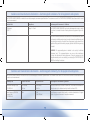
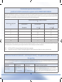
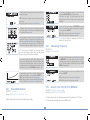
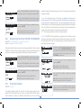
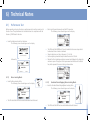
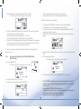
Manufacturer
Warnings:
• Read the entire User Manual before attempting to use the device.
• Use of cables or accessories other than those supplied with the STIMPOD may
result in serious injury.
• Maintenance on this device may only be performed by the manufacturer or
persons explicitly authorized by the manufacturer.
• Do not use the STIMPOD in close proximity to equipment that produces strong
electromagnetic fields, such as high frequency surgical equipment. The cable leads
could act as antennae and dangerous currents could be induced as a result.
• Do not apply the STIMPOD to patients with implanted electrical devices, such as
cardiac pacemakers, without first consulting with an appropriate medical specialist.
• The device should not be used adjacent to or stacked with other equipment and
that if adjacent or stacked use is necessary, the device should be observed to verify
normal operation in the configuration in which it will be used.
• The patient should avoid contact with metallic objects that are grounded, produce
an electrical conductive connection with other equipment and/or enable capacitive
coupling.
• The cables should be positioned in such a way that they do not contact either the
patient or other cables.
• Simultaneous connection of a patient to high frequency surgical ME equipment
and the STIMPOD may result in burns and possible damage to the stimulator.
• Operation in close proximity (e.g. 1m) to a shortwave or microwave therapy ME
equipment may produce instability in the stimulator output.
• Application of electrodes near the thorax may increase the risk of cardiac fibrillation.
Xavant Technology PTY (LTD)
Unit 102, The Tannery Industrial Park, 309 Derdepoort Rd
Silverton, Pretoria, South Africa, 0184
Tel: +27 (0) 12 743 5959
Fax: +27 (0) 86 547 0026
E-mail:[email protected]
Web:www.xavant.com
Legal Representative in the EU
Emergo Europe
15 Molenstraat, 2513 BH, The Hague
The Netherlands
Caution
Federal (US) law restricts this device to sale by or on the order of a physician.
Indications for use:
This product is a nerve stimulation device designed to be used by an
anaesthetist during
• General Anaesthesia, for the purpose of establishing the efficacy of a
Neuromuscular Blocking Agent using non-invasive surface electrodes (not supplied) (NMS450).
•• Regional Anaesthesia for the purpose of
• Nerve mapping using the non-invasive Nerve Mapping Probe (supplied).
• Nerve locating using invasive electrodes/needles (not supplied).
Cautions:
• Prior to changing the batteries be sure to switch off the device and remove all the
cables.
• Remove elements which may adversely affect the connection between the
electrodes and the skin, e.g., dirt, hair, oil.
• Ensure that ECG electrodes are not damaged or dried out.
• Large current densities associated with failing ECG electrodes may cause superficial
burns.
Contraindications:
• Infection of the puncture site.
• Known neurological disorders.
• Severe coagulation disorders.
i
• The Stimpod is designed to be compatible with a standard ECG electrode, however, for high currents the use of a dedicated NMBA electrode such as the Xavant
XT45008 (-NA) is recommended.
• Electrodes that have current densities exceeding 2mA/cm2 may require special
attention of the operator.
• This product must be stored at 0 – 50°C.
• This product must be transported in the carry case provided.
• This product and all the accessories have been certified latex free.
Warranty:
• The Stimpod (device only) carries a 24 Month Warranty against defects, provided
that the device was used in accordance with the operating instructions.
• The cables included in the Stimpod Kit carry a 6 Month Warranty against defects,
provided that they were used in accordance with the operating instructions.
• The Stimpod enclosure should not be opened under any circumstances. Opening
the unit will void the warranty.
STIMPOD (NMS410/450) conforms to the following
standards:
• IEC 60601-1, IEC 60601-2-10
• IEC 60601-1-2: CISPR 11 Group1 class A; IEC 61000-4-2; IEC 61000-4-3
• ISO 13485, Directive 93-42-EEC
ii
Guidance and manufacturers declaration – electromagnetic emissions– for all equipment and systems
The STIMPOD NMS410/NMS450 is intended for use in electromagnetic environment specified below. The customer or user of the STIMPOD NMS410/NMS450 should assure that it is used
in such an environment
Emission Test
Compliance
Electromagnetic Environment – Guidance
RF Emissions
CISPR 11
Group 2 – Class A
The STIMPOD NMS410/NMS450 must emit electromagnetic energy in order
to perform its intended function. Nearby electronic equipment may be affected.
The STIMPOD NMS410/NMS450 is suitable for use in all establishments, other
than domestic establishments and may be used in domestic establishments and
those directly connected to the public low voltage power supply network that
supplies buildings used for domestic purposes, provided the following warning
is heeded:
WARNING: This equipment/system is intended to be used by healthcare
professional only. This equipment/system may cause radio interference
or disrupt the operation of nearby equipment. It may be necessary to take
mitigation measures, such as re-orienting or re-locating the STIMPOD NMS410/
NMS450 or shielding the location
Guidance and manufacturers declaration – electromagnetic immunity- for all equipment and systems
The STIMPOD NMS410/NMS450 is intended for use in the electromagnetic environment specified below. The customer or the user of the STIMPOD NMS410/NMS450 should assure that it
is used in such an environment
Immunity Test
IEC 60601 test level
Compliance level
Electromagnetic environment - guidance
Electrostatic discharge (ESD)
IEC 61000-4-2
± 6 kV contact
± 8 kV air
± 6kV contact
± 8kV Air
Floors should be wood, concrete or ceramic tile. If the floors are covered with
synthetic material, the relative humidity should be at least 30%
Power frequency (50/60 Hz)
magnetic field
IEC 61000-4-8
3 A/m
50 Hz
3 A/m (Effective)
Power frequency magnetic fields should be at levels characteristic of a typical
location in a typical commercial or hospital environment.
iii
Guidance and manufacturer’s declaration – electromagnetic immunity
The STIMPOD NMS410/NMS450 is intended for use in the electromagnetic environment specified below. The customer or the user of the STIMPOD NMS410/NMS450 should assure that it
is used in such an environment.
Immunity test
IEC 60601 test level
Compliance level
Electromagnetic environment – guidance
Portable and mobile RF communications equipment should be used no closer
to any part of the STIMPOD NMS410/NMS450, including cables, than the
recommended separation distance calculated from the equation applicable to
the frequency of the transmitter.
Recommended separation distance
Conducted RF
IEC 61000-4-6
3 Vrms
150 kHz to 80 MHz
Not applicable
Radiated RF
IEC 61000-4-3
3 V/m
80 MHz to 2,5 GHz
3 V/m
d = 1,2 80 MHz to 800 MHz
d = 2,3 800 MHz to 2,5 GHz
where P is the maximum output power rating of the transmitter in watts (W)
according to the transmitter manufacturer and d is the recommended separation
distance in metres (m).
Field strengths from fixed RF transmitters, as determined by an electromagnetic
site survey, a should be less than the compliance level in each frequency range.
Interference may occur in the vicinity of equipment marked with the following
symbol:
NOTE 1 NOTE 2 a
At 80 MHz and 800 MHz, the higher frequency range applies.
These guidelines may not apply in all situations. Electromagnetic propagation is affected by absorption and reflection from structures, objects and people.
Field strengths from fixed transmitters, such as base stations for radio (cellular/cordless) telephones and land mobile radios, amateur radio, AM and FM radio broadcast and TV
broadcast cannot be predicted theoretically with accuracy. To assess the electromagnetic environment due to fixed RF transmitters, an electromagnetic site survey should be
considered. If the measured field strength in the location in which the STIMPOD NMS410/NMS450 is used exceeds the applicable RF compliance level above, the STIMPOD NMS410/
NMS450 should be observed to verify normal operation. If abnormal performance is observed, additional measures may be necessary, such as re-orienting or relocating the STIMPOD
NMS410/NMS450.
iv
Recommended separation distances between
portable and mobile RF communications equipment and the STIMPOD NMS410/NMS450
The STIMPOD NMS410/NMS450 is intended for use in an electromagnetic environment in which radiated RF disturbances are controlled. The customer or the user of the STIMPOD NMS410/
NMS450 can help prevent electromagnetic interference by maintaining a minimum distance between portable and mobile RF communications equipment (transmitters) and the STIMPOD
NMS410/NMS450 as recommended below, according to the maximum output power of the communications equipment.
Rated maximum output power
W
Separation distance according to frequency of transmitter
m
150 kHz to 80 MHz
80 MHz to 800 MHz
800 MHz to 2,5 GHz
Not applicable
d = 1,2
d = 2,3
0,01
-
0,12
0,23
0,1
-
0,38
0,73
1
-
1,2
2,3
10
-
3,8
7,3
100
-
12
23
For transmitters rated at a maximum output power not listed above, the recommended separation distance d in metres (m) can be estimated using the equation applicable to the frequency
of the transmitter, where P is the maximum output power rating of the transmitter in watts (W) according to the transmitter manufacturer.
NOTE 1 NOTE 2 At 80 MHz and 800 MHz, the separation distance for the higher frequency range applies.
These guidelines may not apply in all situations. Electromagnetic propagation is affected by absorption and reflection from structures, objects and people.
Guidance and manufacturers declaration – electromagnetic immunity – for equipment and systems that are nonlife supporting
The STIMPOD NMS410/NMS450 is intended for use in the electromagnetic environment specified below. The customer or the user of the STIMPOD NMS410/NMS450 should assure that it
is used in such an environment
Immunity Test
IEC 60601 test level
Compliance level
Electromagnetic environment - guidance
Radiated immunity
80MHz - 2.5GHz
80MHz – 1GHz @ 3V/m &
10V/m
1GHz – 2.5GHz @ 10V/m
80MHz – 1GHz @ 3V/m &
10V/m
1GHz – 2.5GHz @ 10V/m
Portable and mobile RF communications equipment can affect MEDICAL
ELECTRICAL EQUIPMENT and should be used no closer to any part of the
equipment, including cables, than the recommended separation distance.
v
Contents
Page
1.
1
Getting to know the STIMPOD (NMS 410/450)
1.1) Device Description
1.2)Accessories
1.3) Device Layout
1.4) Screen Layout
1.5) Warning Screens
1.6) Open Circuit Detection
1.7) Auto Shutdown
1.8) Symbols on device battery clip
1
2
3
4
5
6
6
6
2. Operating Device in Nerve Locating Mode (NMS 410/450)
7
2.1)
2.2)
2.3)
2.4)
Proximity Indicator
Adjusting the Current
Adjusting the Pulse Width
Adjusting the Twitch Frequency
7
8
8
8
3. Operating Device in Nerve Mapping/Locating
Mode (NMS 410/450)
3.1) Adjusting the Current
3.2) Adjusting the Pulse Width
3.3) Adjusting the Twitch Frequency
Page
4.6)
4.7)
4.8)
4.9)
4.10)
4.11)
4.12)
Train of Four Mode (TOF)
Double Burst Mode (DB)
Post Tetanic Count Mode (PTC)
Refractory Period Delay Twitch Mode
Tetanus Mode
Single Stimulus vs. Repeated Stimulation
12
13
13
13
14
14
14
5. Setting up Device Defaults 5.1)Languages
5.2) Current Mode
5.3) Pulse Width Options
5.4) Stimulating Frequency
5.5) Repeat Timer TOF, DB, PTC (NMS450)
5.6) Refractory Period Timer TOF, DB, PTC (NMS450)
5.7) Proximity Indicator
5.8) Speaker Volume
5.9)Backlight
5.10) User Information
9
10
10
10
6. Technical Notes
6.1) Performance Testing
6.2)Specifications
6.3) Cleaning and Disinfecting STIMPOD
4. Operating Device in Neuromuscular Blocking Agent 11
(NMBA) Monitoring Mode (NMS 450)
7. Products & Accessories
4.1) Electrode Placement
11
4.2)
4.3)
4.4)
4.5)
Accelerometer Placement
Adjusting the Current
Adjusting Stimulation Mode
Adjusting the Twitch/ Tetanus Frequency
11
12
12
12
vi
15
15
16
18
18
18
19
19
20
20
20
21
21
23
23
24
1) Getting to know the STIMPOD (NMS 410/450)
1.1)
Device Description
The STIMPOD (NMS 410/450) is a precision nerve locating tool used for localizing specific neural pathways. Localization of nerves by electrical stimulation involves
connecting the nerve stimulator to a conducting needle through which local anaesthetics can be injected. The distance of the needle (cathode) from the nerve can
be estimated by establishing the minimum threshold current required, to facilitate a neuromuscular response.
The STIMPOD (NMS 450) includes Neuromuscular Blocking Agent Monitoring functionality with real-time feedback achieved by tri-axial accelerometry.
CAUTION: This device should only be used by a qualified physician with appropriate knowledge in anaesthesia.
CAUTION: The sale or purchase of the device is restricted to licensed medical practitioners, as governed by the law of the country/state in which he/she practices, or
where the device is to be used.
1
1.2)Accessories
WARNING: Use of cables or other accessories other than those supplied with the STIMPOD may result in serious injury.
NOTE: Electrodes and Nerve Locating needles are not included in this package.
CAUTION: A sterile wipe should be applied to the Nerve Mapping Probe prior to use.
Nerve Locating Cable:
• This cable is used to activate the Nerve Locating mode on the STIMPOD.
• The red (anode) connector is designed to clip on to a standard ECG electrode.
• The 2mm needle connector will accommodate various makes of needles.
Nerve Mapping/ Nerve Locating Cable:
• This cable is used to activate the Nerve Mapping/ Nerve Locating mode on the STIMPOD.
• The red (anode) connector is designed to clip on to a standard ECG electrode.
• The ergonomically designed cutaneous Nerve Mapping Probe presents the user with a simple and
reliable Nerve Mapping solution.
• The 2mm needle connector will accommodate various makes of needles.
NMBA Monitoring Cable (NMS450):
• This cable is used to activate the NMBA mode on the STIMPOD.
• The red (anode) and black (cathode) connectors are designed to clip onto the Xavant NMBA
electrode (XT45008) (-NA) or onto a standard ECG electrode.
• The accelerometer is designed to attach to the contracted appendage (in the case of the ulnar
nerve, this will be the thumb).
Carry Case
Batteries:
• This unit uses 4 x AAA penlight batteries.
• Lithium batteries are recommended.
• When the battery is depleted the unit will prompt the user to replace the battery and switch off.
• Switch device off and remove all cables before replacing battery.
• Remove battery if the device is not to be used for an extended period of time, to prevent
leakage.
WARNING: If battery acid has leaked into the device essential circuitry may have been compromised. In the event of leakage the device must be returned to its
manufacturer for safety checks and possible repairs.
2
1.3)
Device Layout
Cable Connector
• Insert the Nerve Locating Cable, the combined Nerve
Mapping / Locating Cable or the NMBA cable to
activate the relevant mode.
Display
Multi Functional Clip
Enter / Frequency Button
• Press to toggle between Frequencies.
• Press to Enter in setup menu.
Menu / Pulse Width Button
NMS410/450 (LOC/MAP Mode)
• Press to toggle between Pulse Widths.
• Press and hold to access Setup Menu.
NMS 450 (NMBA Mode)
• Press to toggle between Stimulation Modes.
Stimulating LED indicator
• Flashing Green: Stimulus delivered.
• Flashing Red: Open Circuit.
Pause Button
NMS 410/450 (LOC/MAP Mode)
• Press to Stop / Start Stimulation.
NMS 450 (NMBA Mode)
• Press and release to elicit a single stimulation.
• Press and hold to activate a repeated stimulation.
The Wheel
• Adjust current in the main operating mode.
• Navigate the Setup Menus.
Battery Compartment Cover
On / Off Button
• Press to switch unit on / off.
3
1.4)
Screen Layout
Indicators
Nerve locating mode
Nerve mapping mode NMBA mode (NMS450)
Non-Linear mode Linear mode
Speaker Volume
Battery Status
Warning
Main Screen
Notifies the user of a discrepancy
between current setting and average
current of actual stimulus.
• Current Setting
Adjust using Wheel.
• Diagnostic or Warning Screen
• Average current of actual stimulus
• Pulse Width Setting
Adjust using Menu / Pulse Width button.
Warning Screens
• NMBA Mode (NMS 450)
Stimulation Mode TOF, DB, PTC, TET, TWI.
• Stimulating Frequency Setting
Adjust using Enter / Hz button.
Explained on Page 5.
Diagnostic Screen NMS 450 (NMBA Mode)
Diagnostic Screen NMS 410 / 450 (LOC / MAP Mode)
• Countdown timer
• Real-time feedback of for repeat mode
relative contraction strength
measured with the accelerometer
• Calculated
• Proximity indicator arrow
Charge
Setting
• Indication of current setting
• 0 mA
• Graph indicating shape of actual current stimulus
• Calculated percentage in TOF and DB mode
• Twitch Count in PTC and TOF if less than 4 contractions
were indentified
• Average charge of
actual stimulus
4
1.5)
Warning Screens
Insert Cable:
This is the first prompt which the user will encounter as the unit is switched on, and signals that the unit is waiting
for the cable to be inserted.
Pause:
This warning informs the user that the PAUSE button was pressed.
The STIMPOD will pause all its activities and wait for the PAUSE button to be pressed again.
Cable not recognised:
This warning informs the user that the inserted cable is not compatible with the NMS 410/450.
Replace Batteries:
This warning informs the user that the batteries are depleted beyond an acceptable level. Continuing to operate
the device thus will make it unreliable. To prevent this the STIMPOD flashes this warning for 4 seconds before
switching off.
Open Circuit Detected:
This warning informs the user that the two electrodes (i.e. ECG electrode and needle or mapping device) do not form
a closed circuit. This warning will be accompanied by a red flashing LED, every time the unit attempts to stimulate.
Current Adjustment in NMBA Mode:
When attempting to adjust the current while in NMBA mode the device will show this message, requesting the
user to confirm the adjustment of the current.
Refractory
Delay Active
Press Enter
To Confirm
Refractory Delay Active:
Once a TOF, DB, or PTC stimulation is performed, the refractory period timer is initiated. During the countdown time
it will not be possible to perform another stimulation. If another stimulation is attempted, this warning screen will
appear.
Component Error:
The STIMPOD has detected a component failure. Please send the device back to the manufacturer for repair!
55
1.6)
Open Circuit Detection
The Stimpod performs impedance measurements at regular intervals to detect
whether the connection between the STIMPOD and the patient comprises a
closed circuit.
Closed Circuit Detected:
Open Circuit Detected:
• Stimulation will take place.
• Stimulating sound will be heard (Single or multiple beeps depending on
proximity indicator setting. Sound pitch will follow the current intensity).
•The LED stimulus indicator will pulse green with every successful stimulus
attempt.
•The diagnostic screen will provide active feedback on every pulse delivered.
• No stimulation will take place.
• No stimulating sound will be heard.
•The LED stimulus indicator will pulse red with every unsuccessful stimulus
attempt.
•A warning screen will appear in the diagnostics screen indicating that an
open circuit was detected.
1.7) Auto Shutdown
STIMPOD will shutdown after 10 minutes of no user or patient interaction.
1.8) Symbols on device battery clip
Manufacturer
Type BF
Applied Part
Caution
Separate collection for electrical
and electronic equipment
(Applicable to EU community only)
Consult instructions
for use
6
Manufacturing Date
(Year)
Serial Number
Representative
in the EU
2) Operating Device in Nerve Locating Mode
(NMS 410/450)
Localisation of nerves by electrical stimulation involves connecting the nerve stimulator to a conducting, locating needle (not supplied) through which local anaesthetics
can be administered. This procedures involves subcutaneous stimulation of the motor component of the relevant peripheral nerve, to ‘locate’ the nerve.
• Select this mode by inserting the Nerve Locating cable.
• The STIMPOD will automatically default to the Nerve Locating current range
(0.00 - 5.00 mA) and display the ‘ LOC ’ indicator.
2.1)
Proximity Indicator
The proximity indicator is activated when the combination of current and pulse width settings result in a charge which is within the range as selected in the SETUP
MENU, section 5.7.
Visual Indication:
• Visually indicated in the diagnostics screen by two arrowheads.
• Arrowhead indicating the lower threshold points upwards.
• Arrowhead indicating the upper threshold points downwards.
•The dotted line representing the selected current will be positioned between
the two arrowheads if the target charge range is entered.
Audible Indication:
• A successful stimulus above the proximity range will make a single beep.
• A successful stimulus within the proximity range will make a double beep.
• A successful stimulus below the proximity range will make a triple beep.
77
2.2)
Adjusting the Current
Current Mode Options:
Sound:
Options in the Setup Menu: Linear Mode, Non-Linear Mode
Default: Linear
If sound is enabled: STIMPOD will beep every time that a stimulus was
delivered. The pitch of the sound will follow the current intensity level.
Linear Mode:
Non-Linear Mode:
The Linear Mode is called linear because one ‘click’ on the Wheel will correspond
with one increment as set in the specific current range. The Linear Mode allows
the user to select individual incrementing options for the three different current
ranges.
The Non-Linear Mode facilitates the non-linear nature of the current intensity
versus the distance from the nerve.
This mode allows the user to define 20 adjustment positions in terms of Current
(mA) and Pulse Width (ms). If correctly implemented each adjustment position
should afford the user with a relatively linear progression in terms of the distance
from needle tip to the nerve.
Default Current range:
0.00 - 5.00mA adjustable in the following default increments:
0.0 - 0.6mA Default 0.1mA
0.6 - 2.0mA Default 0.2mA
2.0 - 5.0mA Default 0.5mA
Default Current and Pulse Width Range:
As shown in table 5.1 in section 5.2 circle the Wheel to select the
predetermined current and pulse width positions sequentially.
Increments can be adjusted in the Setup Menus
(refer to 5.2)
NOTE: Because the 20 definable positions
include both current and pulse width settings, pulse width cannot be adjusted independently in this mode. This is indicated on the screen by the fact that pulse width is not highlighted.
Circle the Wheel to adjust current.
Warning
Notifies the user of a discrepancy between current
setting and average current of actual stimulus.
Average of actual current delivered.
2.3)
Adjusting the Pulse Width
2.4)
Options in the Setup Menu: 0.05ms, 0.1ms, 0.3ms, 0.5ms, 1ms
Default: 0.1ms, 0.3ms
Press Menu/Pulse Width button to toggle between different Pulse Widths.
Adjusting the Twitch Frequency
Options in the Setup Menu: 1Hz, 2Hz, 5Hz
Default: 2Hz
Press Enter/Hz button to toggle between different stimulating frequencies.
8
3) Operating Device in Nerve Mapping/Locating Mode (NMS 410/450)
Percutaneous nerve mapping enables the anaesthesiologist to map out a particular superficial nerve prior to nerve location with the needle. This is accomplished by
stimulating the motor component of the relevant peripheral nerve percutaneously with the nerve mapping probe. This technique ensures a higher success rate for
directing the needle to the correct nerve.
This mode offers the user the means to do nerve mapping and locating without having to switch or unplug cables.
When inserting the Nerve Mapping / Locating Cable, the STIMPOD will default to the Nerve Mapping current range (0-20mA). Current will be directed to the Nerve
Mapping probe and the STIMPOD will attempt to stimulate. The moment that the needle penetrates the skin the cable will sense it and inform the STIMPOD. The
STIMPOD will switch to Nerve Locating mode and behave as described in chapter 2. If contact between the needle and patient is broken, and the nerve mapping
probe touches the patient, STIMPOD will switch back to the nerve mapping mode and start monitoring the needle - patient connection again. Whenever the nerve
mapping probe and the nerve locating needle simultaneously make contact with the patient the needle will have first priority.
• This mode is selected when the Nerve Mapping / Locating cable is inserted.
99
When using the Nerve Mapping Probe (NMS 410/450):
Sound:
•The STIMPOD will automatically default to the Nerve Mapping current range
(0-20mA) and display the ‘ MAP ’ indicator.
3.1)
If sound is enabled: STIMPOD will beep every time that a stimulus was
delivered. The pitch of the sound will follow the current intensity level.
Adjusting the Current
Average of actual current delivered.
Current Range: 0 - 20mA adjustable in 1mA
increments.
Circle the Wheel to adjust current.
Warning
Notifies the user of a discrepancy between current
setting and average current of actual stimulus.
3.2) Adjusting the Pulse Width
3.3)
Options in the Setup Menu: 0.05ms, 0.1ms, 0.3ms, 0.5ms, 1ms
Default: 0.1ms, 0.3ms
Press Menu/Pulse Width button to toggle between different pulse widths.
Adjusting the Twitch Frequency
Options in the Setup Menu: 1Hz, 2Hz, 5Hz
Default: 2Hz
Press Enter/Hz button to toggle between different stimulating frequencies.
When using the Nerve Locating Needle:
• Connect the needle to the Nerve Mapping/Locating cable. The moment that the needle penetrates the skin the cable will communicate this to the STIMPOD,
switch to nerve locating mode, and switch the stimulation to the needle. The current in locating mode will default to 0.00mA.
• The STIMPOD will now function exactly as described in Chapter 2.
• If contact between the needle and patient is broken, and the nerve mapping probe touches the patient, STIMPOD will switch back to the nerve mapping mode
and start monitoring the needle - patient connection again. Mapping mode will default back to 0mA.
• Whenever the nerve mapping probe and the nerve locating needle simultaneously make contact with the patient the needle will have first priority.
10
4) Operating Device in Neuromuscular Blocking Agent Monitoring Mode (NMS 450)
Monitoring Neuromuscular Blocking Agents involves stimulating a neural pathway which facilitates the contraction of an appendage. Based on the relative strength of
contraction which is the result of a stimulus of specific intensity or waveform, it is possible to draw conclusions about the efficacy of an injected Neuromuscular Blocking
Agent.
• This mode is selected when the NMBA cable is inserted.
4.1) Electrode Placement
4.2) Accelerometer Placement
4.1.1) Anatomical stimulation sites are chosen based on:
• their accessibility during surgery
• the ability to observe the neuromuscular response
• the nerve should be a suitable distance from the responding muscle to prevent
direct muscle stimulation
The tri-axial accelerometer should be attached to the contracting appendage of
the patient, to measure the strength of the contraction resulting from the applied
electrical stimulus. The accelerometer is only used in the Train-of-Four, Double
Burst and Post Tetanic Count Modes, to facilitate monitoring of the efficacy of the
Neuromuscular Blocking Agent.
4.1.2) Anatomically ideal stimulation sites:
Targeted Nerve
Affected Muscle
Contracting Appendage
Ulnar nerve
adductor pollicis muscle
Thumb
Posterior tibial nerve
flexor halluces brevis muscle
Big toe
Facial nerve (Zygomatic
Branch)
orbicularis oculi muscle
Eye lid
Facial nerve (Temporal
Branch)
corrugator supercili muscle
Eye brow
Electrode placement relies on the cathode (black electrode clip) to be as close to
the targeted nerve as possible in order to effectively depolarize the nerve. The
anode (red electrode clip) should be away from the targeted nerve.
11
11
When using the Neuromuscular Blocking Agent Monitoring Mode (NMS 450):
4.3)
Adjusting the Current
Sound:
If sound is enabled: STIMPOD will beep every time that a stimulus was
delivered. The pitch of the sound will follow the current intensity level.
When attempting to adjust the current in NMBA
mode the Stimpod will show a message requesting
to confirm the adjustment of current. When this message appears, press the ‘enter’ button. This will cause
the current intensity to flash on and off, which means
that the current can now be adjusted.
Average of actual current delivered.
Warning
Notifies the user of a discrepancy between current
setting and average current of actual stimulus.
If current has not been adjusted for more than 2
seconds, the current will be set.
Default Current range:
0 - 80 mA adjustable in 5mA increments.
Circle the Wheel to adjust current.
4.4)
4.6)
Adjusting Stimulation Mode
The TOF stimulation comprises four, square waves with a pulse width of 200
microseconds, 500 milliseconds apart.
Options: TOF, DB, PTC, TET, TWI
Default: TOF
Press Menu/Mode button to toggle between different Stimulation Modes.
4.5)
Train of Four Mode (TOF)
Selecting TOF Mode:
• Insert the NMBA cable with the red and black electrode clips as well as the tri-axial
accelerometer.
• Press the ‘Mode’ button until ‘TOF’ is
shown on the display.
Adjusting Twitch/Tetanus Frequency
Twitch Mode:
Real-time Accelerometry:
• The relative contraction strength
caused by each stimulus is indicated
graphically in the diagnostic screen as
shown in the picture.
• In the case that all four contractions could be measured, the percentage of
measured contraction strength of the fourth stimulus compared to the first
stimulus will be displayed in the diagnostic screen.
• If less than four contractions were measurable, the number of contractions
that could be identified by the accelerometer will be displayed, e.g., 2/4.
Options in the Setup Menu (Stimulating Frequency): 1Hz, 2Hz, 5Hz
Default: 2 Hz
Press Enter/Hz button to toggle between
different stimulation frequencies.
Tetanus Mode:
Options: 50Hz, 100Hz
Default: 50Hz
Press Enter/Hz button to toggle between different stimulating frequencies.
12
4.7)
Double Burst Mode (DB)
4.8)
Post Tetanic Count (PTC)
The DB stimulation comprises a burst of three square waves of 200
microseconds pulse width, 20 milliseconds apart, followed by another burst of
three square waves, 750 milliseconds later.
Defaults:
Tetanus: 50Hz for 5 seconds
Delay: 3 seconds
Twitch: 20 twitches at 1Hz
Selecting DB Mode:
• Insert the NMBA cable with the red and black electrode clips as well as the
tri-axial accelerometer.
• Press the ‘Mode’ button until ‘DB’ is shown on the display.
The PTC stimulation comprises a tetanus stimulation followed by a delay and a
number of twitches. (Default settings are as shown above)
Selecting PTC Mode:
• Insert the NMBA cable with the red and black electrode clips as well as the
tri-axial accelerometer.
• Press the ‘Mode’ button until ‘PTC’ is shown on the display.
Real-time Accelerometry:
• The relative contraction strength
caused by each stimulus is indicated
graphically in the diagnostic screen as
shown in the picture.
• The percentage of the measured
contraction strength of the second contraction compared to the first
contraction will be displayed in the diagnostic screen.
4.9)
Real-time Accelerometry:
• Each counted twitch is indicated
graphically in the diagnostic screen
as shown in the picture.
The number of twitches counted are
displayed in the diagnostic screen.
Refractory Period Delay
The three modes: TOF, DB and PTC are subject to refractory period delays, providing a safety period which prevents the user from repeating stimulation while the
nerve synapse is recovering from the effects of the previous stimulation.
Immediately after stimulation in one of these modes, the countdown timer is activated and shown on the screen. If repeat mode is activated, only the repeat timer
will be displayed on the screen because the repeat period for the repeat timer will always be larger than the refractory period timer. If an attempt is made to stimulate while the refractory timer is active a warning screen will be displayed reminding the user that the refractory period is active.
Default refractory period delays are as follows for the three modes:
TOF:
15 seconds
DB: 1 minute
PTC: 2 minute
13
4.10) Twitch (TWI)
4.11) Tetanus (TET)
Defaults: Repeat at 2Hz
Adjustable:1Hz, 2Hz and 5Hz
Defaults:50Hz (adjustable to 100Hz)
The Tetanus stimulation comprises series of 200 microseconds square wave
pulses repeated at a 50Hz or 100Hz repetition rate or frequency.
The Twitch stimulation comprises a 200 microseconds square wave pulse. If the
‘Play/Pause’ button is pressed the twitch will repeat at the selected frequency.
Selecting TET Mode:
• Insert the NMBA cable with the red and black electrode clips as well as the
tri-axial accelerometer.
• Press the ‘Mode’ button until ‘TET’ is shown on the display.
Selecting TWI Mode:
• Insert the NMBA cable with the red and black electrode clips as well as the
tri-axial accelerometer.
• Press the ‘Mode’ button until ‘TWI’ is shown on the display.
Stimulate/Stop:
Start stimulation by holding the
‘Play/Pause’ button down.
Stop stimulation by releasing the
‘Play/Pause’ button.
Stimulate/Stop:
Start stimulation by pressing the
‘Play/Pause’ button. Stop stimulation by
pressing the ‘Play/Pause’ button again.
Frequency adjustment:
Press the ‘Hz’ button to toggle through the frequencies.
4.12) Single Stimulus vs. Repeated Stimulation
•
•
•
•
•
Start the automatic repeat mode by holding the play/pause button down for longer than 2 seconds.
The device will automatically start a countdown according to the ‘repeat timer’ setting as specified in the main menu for each respective mode’s timer.
The countdown will be indicated next to the clock symbol shown in the diagnostic screen.
Disable the automatic repeat mode by pressing and holding the play/pause button again.
The Repeat Timer for each mode defaults at 2 minutes and can be changed in the menu.
14
5) Setting up Device Defaults (NMS 410/450)
Access the Setup Menu by pressing and holding the Menu/Pulse Width
Button. The setup menu allows the user to customise all the default settings.
SETUP MENU
1 LANGUAGE
2 CURRENT MODE
3 PULSE WIDTH
4 FREQUENCY
5 REPEAT TIMER TOF
6 REPEAT TIMER DB
7 REPEAT TIMER PTC
8 REFRACTORY TIME TOF
9 REFRACTORY TIME DB
10 REFRACTORY TIME PTC
11 PROXIMITY INDICATOR
12 SPEAKER VOLUME
13BACKLIGHT
14 USER INFORMATION
EXIT
5.1) Languages
DEFAULT: English
Use the Wheel to navigate to LANGUAGE. Press enter to select.
To select another default language, use the Wheel to
navigate to the preferred language. Press enter to select.
The radio button next to the selected language will show
that it is activated. To exit scroll down the menu to EXIT
MENU and press enter.
A confirmation screen will show your selection, with an
option to ACCEPT.
YES will take you back to the main Setup Menu.
NO will take you to the previous screen.
Note: The NMS410 does not have the REPEAT TIMER or REFRACTORY TIMER
options.
15
15
5.2) Current Mode
The first range will be: 0.00mA - 0.60mA. In this range
the user can select one of the following increment
options: 0.01mA, 0.02mA, 0.05mA and 0.1mA. The default
setting is: 0.05mA. Select the desired increment and
proceed to NEXT RANGE.
DEFAULT: Linear Mode
Options: Linear Mode, Non-Linear Mode
Linear Mode
The second range will be 0.6mA - 2.0mA. In this range
the user can select one of the following increment
options: 0.05mA. 0.1mA and 0.2mA. The default setting
is: 0.1mA. Select the desired increment and proceed to
NEXT RANGE.
The `
` indicator in the main window tells the user that the device is in
Linear Mode.
The linear mode is called linear because one ‘click’ on the wheel will correspond
with one increment as set in the specific current range. In the linear mode, Pulse
Width is not affected when turning the wheel. Pulse Width is selected when the
Menu/Pulse Width button is pressed. The Linear Mode essentially allows the user
to select three different increment options for three different current ranges.
The third range will be: 2.0mA - 5.0mA. In this range
the user can select one of the following increment
options: 0.1mA, 0.2mA and 0.5mA. The default setting
is: 0.2mA. Select the desired increment and proceed to
EXIT MENU.
Use the Wheel to navigate to CURRENT MODE. Press enter to select.
Use the Wheel to navigate to Current Mode. Press enter
to select. The radio button next to Linear Mode will show
that it is activated. To exit scroll down the menu to EXIT
MENU and press enter.
A confirmation screen will show your selection, with an
option to ACCEPT.
YES will take you back to the main Setup Menu.
NO will take you back to Linear Mode settings.
A confirmation screen will show your selection, with an
option to ACCEPT.
Non - Linear Mode
YES will take you to the next screen.
NO will take you to the Current Mode Menu.
The `
` indicator in the main menu window tells the user that the
device is in Non-Linear Mode. The Non-Linear Mode facilitates the
non-linear nature of the current intensity versus the distance from the
nerve. The required current intensity is proportional to the square of the
distance from the electrode to the nerve fibre.
This mode allows the user to define 20 adjustment positions in terms of
Current (mA) and Pulse Width (ms). If correctly implemented each
adjustment position should afford the user a relatively linear progression in
terms of the distance from needle tip to the nerve. The defaults are
indicated in table 5.1. A graph of table 5.1 is shown in figure 5.1.
The next screen will enquire whether the user would like to
change the settings.
YES will take you to the next screen.
NO will take you back to the main Setup Menu.
16
Position
Current
(mA)
Pulse Width (ms)
Charge
(µC)
1
0.3
0.1
0.03
2
0.43
0.1
0.043
3
0.58
0.1
0.058
4
0.76
0.1
0.076
5
0.97
0.1
0.097
6
1.2
0.1
0.12
7
1.4
0.1
0.14
8
1.7
0.1
0.17
9
2
0.1
0.2
10
2.3
0.1
0.23
11
2.7
0.1
0.27
12
3
0.1
0.3
13
3.4
0.1
0.34
14
3.8
0.1
0.38
15
4.3
0.1
0.43
16
4.8
0.1
0.48
17
1.8
0.3
0.54
18
2.1
0.3
0.63
19
2.4
0.3
0.72
20
2.7
0.3
0.81
It should be noted that the charge of the default values shows a typical quadratic
curve. At a pulse width of 0.1ms the current follows the charge.
1
2
3
4
5
6
Charge
7
8
9
10
11 12
Current
13 14 15
16
17 18 19 20
Pulse Width
Figure 5.1
Once a limit of 5mA is reached the pulse width is increased to 0.3ms. After 0.3ms the
slope of the charge on the graph is increased.
NOTE: Each position in this adjustment mode can be defined individually. The user
is advised to experiment and adjust the values in order to meet clinical expectations.
NOTE: In this mode the Pulse Width is preset and linked to a specific position.
When operating the device in this mode the Pulse Width button is deactivated. All
positions are accessed sequentially by manipulating the wheel.
Use the Wheel to navigate to CURRENT MODE. Press enter to select.
To adjust the default position values, use the Wheel to
navigate to Non-Linear Mode. Press enter to select. The
radio button next to Non-Linear will show that it has been
activated.
A Confirmation screen will show your selection with an
option to ACCEPT.
Table 5.1
YES will take you to the next screen.
NO will take you back to the Current Mode Menu.
17
17
The next screen will enquire whether the user would like to
change the settings.
To change the default pulse widths, use the Wheel to
navigate to PULSE WIDTH in the main menu.
Press enter to select. The radio button next to the
selected pulse width will show that they have been
activated.
YES will take you to a screen showing all the positions and
their values.
NO will take you back to the main Setup Menu.
To exit scroll down the menu to EXIT MENU and press
enter. A confirmation screen will show your selection,
with an option to ACCEPT.
YES will take you back to the main Setup Menu.
NO will take you back to the previous screen.
All positions will be shown with their respective current and
pulse width settings. Scroll down to the position that needs
to be adjusted and press enter.
When entering the screen the current setting will be
highlighted. Adjust to the required value and press enter.
Next the pulse width setting will be highlighted. Adjust
to the required value and press enter. The STIMPOD will
calculate and display the charge as adjustments are made.
NOTE: If all pulse widths are deselected the STIMPOD will
default to 0.1ms and 0.3ms.
5.4) Stimulating Frequency
DEFAULT: 2Hz
Options: 1Hz, 2Hz and 5Hz
NOTE: A warning will indicate if the net charge resulting
from the user’s settings is either lower than the previous
position or higher than the following position.
To change the default frequency, use the Wheel to navigate
to FREQUENCY in the main menu. Press enter to select.
The radio button next to the selected frequency will show
that it is has been selected. Scroll down the menu to EXIT
MENU and press enter.
Once a new current and pulse width setting has been
entered for the relevant position, the device will again show
all the positions and their values. The user can now adjust
any other position values following the same steps. To exit,
scroll down the menu and EXIT MENU and press enter.
A confirmation screen will show your selection with an
option to ACCEPT.
A confirmation screen will draw a graph reflecting the net
charge for every position, with an option to ACCEPT.
YES will take you back to the main Setup Menu.
NO will take you back to the screen showing all the positions
with their respective current and pulse width settings.
YES will take you back to the main Setup Menu.
NO will take you back to the previous screen.
5.5) Repeat Timer TOF, DB, PTC (NMS450)
5.3) Pulse Width Options
DEFAULT: 2 minutes for all three modes
Options: Adjustable from 00:00 to 99:59
DEFAULT: 0.1ms, 0.3ms
Options: 0.05ms, 0.1ms, 0.3ms, 0.5ms, 1.0ms
This timer counts down the delay between repeated stimulations in TOF, DB and
PTC modes when operating the device in NMBA mode.
Use this setup function to activate the preferred pulse widths.
18
REPEAT TIMER TOF
Adjust Range:
Minutes: 01
Seconds:20
REPEAT TIMER TOF
You have selected:
01:20 01
ACCEPT: YES NO
5.6) ‘Minutes’ will be highlighted: Use the Wheel to adjust
the settings. Press enter to accept the desired setting.
needle has reached the desired proximity to the nerve. This proximity is indicated both
visually and audibly.
‘Seconds’ will be highlighted: Use the Wheel to adjust
the settings. Press enter to accept the desired setting.
Visually: In the diagnostics screen of the device, the dotted line will indicate the
selected current level. The proximity range will be indicated by two arrowheads on
the right hand side of the diagnostics screen. The arrow representing the lower threshold value will point up and the arrow representing the higher threshold value will point
down. This offers the user visual feedback on the position of the current amplitude at
a specific pulse width, relative to the defined proximity thresholds.
NOTE: The proximity thresholds are defined in charge (Coulomb).
A confirmation screen will show your updated values with
an option to ACCEPT.
YES will take you back to the main Setup Menu.
NO will take you back to the previous screen.
Refractory Period Timer TOF, DB, PTC (NMS450)
DEFAULT: TOF 15 seconds, DB 1 minute, PTC 2 minutes
Options: Adjustable from 00:00 to 99.59
Audibly: The STIMPOD has three different sound patterns when stimulating. A single
beep means that the user is above the upper threshold of the proximity range. A double beep means that the user is in the proximity range. A triple beep means that the
user is below the proximity range.
To change the default Proximity Indicator Levels, use the
Wheel to navigate to PROXIMITY INDICATOR in the main
menu. Press enter to select. Choose On or Off by activating
the correct radio button. To exit scroll down the menu to
EXIT MENU and press enter.
These three individual timers count down the refractory period delays for the three modes
TOF, DB, PTC respectively. Their purpose is to prevent the user from repeating stimulation
while the nerve synapse is recovering from the effects of the previous stimulation.
REFRACTORY TIME TOF
Adjust Range:
Minutes: 04
Seconds:10
REFRACTORY TIME TOF
You have selected:
04:10 01
ACCEPT: YES NO
‘Minutes’ will be highlighted: Use the Wheel to adjust
the settings. Press enter to accept the desired setting.
A confirmation screen will show your selection with an
option to ACCEPT.
‘Seconds’ will be highlighted: Use the Wheel to adjust
the settings. Press enter to accept the desired setting.
YES will take you to the following menu.
NO will take you back to the menu above.
A confirmation screen will show your updated values with
an option to ACCEPT.
Here you have the option to adjust the proximity
thresholds.
YES will take you back to the main Setup Menu.
NO will take you back to the previous screen.
YES will take you to the thresholds adjustment menu.
NO will take you back to the main Setup Menu.
5.7) Proximity Indicator
The lower limit will be highlighted. Adjust using the
adjusting wheel. Press enter to move on to the upper limit.
Adjust the upper limit and press enter.
DEFAULT: 30 - 60 nC
The proximity indicator notifies the user that the target charge range has been
reached. This function allows the user to set up an upper and lower limit of charge.
When contraction is elicited, this indicator should indicate to the user that the
19
19
A confirmation screen will show your updated values with
an option to ACCEPT.
A confirmation screen will show your selection, with an
option to ACCEPT.
YES will take you back to the main Setup Menu.
NO will take you back to the previous screen.
YES will take you back to the main Setup Menu.
NO will take you back to the previous screen.
5.8) Speaker Volume
NOTE: If the selected backlight option is ‘Always On’ the battery life will be drastically
shortened.
The speaker volume offers 4 different options: OFF and 3 different volume settings.
The different volume settings are indicated on the main screen as follows:
5.10) User Information
DEFAULT: Medium
DEFAULT: No default
The STIMPOD offers the user the option to enter user
information. Two lines of 20 characters each may be
entered. This user information will be displayed for two
seconds when unit is switched on, as per example.
To change the speaker volume, use the Wheel to navigate
to SPEAKER VOLUME in the main menu. Press enter to
select. Use the wheel to select the appropriate volume and
enter. Scroll down the menu to EXIT MENU and press
enter.
Use the Wheel to navigate to USER INFORMATION in the
main menu. Press enter to select. A cursor will appear at
the first character’s position. Use the Wheel to navigate to
different characters. Press enter to select the character
and move to the next space.
A Confirmation screen will show the new selected volume
with an option to ACCEPT.
YES will take you to the main Setup Menu.
NO will take you back to the previous screen.
Press enter on the ‘ ‘ character for backspace, on the
‘
’ character for a space and on the ‘ ‘ character to
enter the line.
5.9) Backlight
DEFAULT: 5 Seconds
Options: OFF, 5 seconds, 60 seconds, and Always On
A warning underneath the textbox will show the available
characters in the line.
To change the default Backlight setting, use the Wheel to
navigate to BACKLIGHT in the main menu. Press enter to
select. The radio button next to the selected setting will
show that it has been activated. Scroll down the menu to
EXIT MENU and press enter.
When both lines have been entered, a confirmation screen
will show your selection, with an option to ACCEPT.
YES will take you back to the main Setup Menu.
NO will take you back to the first USER INFORMATION
screen.
20
6) Technical Notes
6.1) Performance Test
Before operating and using the device a performance test must be carried out at
the site of use. The performance test described below is in compliance with the
German § 5 MPBetreibV directive.
•
•
Insert the batteries and switch on the device.
The following screen should appear on the display.
•
NMS4X0
VX.00
•
•
•
User Information
followed by
_._ _
!
6.1.1) •
Short-circuit the needle connector and the ECG connector.
The following screen should appear on the display.
The LED should flash GREEN and if sound is enabled in the menu a beep should
be heard each time a stimulus is delivered.
Stimulus should occur at the set frequency. (1,2 or 5 Hz).
Use the adjusting wheel and slowly increase the current to 5.00mA.
Monitor that the stimulating waveform, measured and displayed in the diagnostic window is square. The top part of the square wave should also touch the dotted
line, which represents the current setting as shown below.
Insert
InsertCable
Cable
Nerve Locating Mode
Insert the Nerve Locating Cable.
The following screen should appear on the display.
6.1.2)
•
0.00
!
Combined Nerve Mapping/Nerve Locating Mode
Insert the Combined Nerve Mapping/Nerve Locating Cable.
The following screen should appear on the display.
Open Circuit
Open
Circuit
Detected
Detected
!
•
Open Circuit
Detected
The LED should flash RED and no audible feedback should be heard.
•
21
The LED should flash RED and no audible feedback should be heard.
•
Short-circuit the Nerve Mapping probe and the ECG connector.
The following screen should appear on the display.
•
•
Use the adjusting wheel and increase the current to 80mA.
Press the ‘play/pause’ button while shaking the accelerometer.
The NMS450 should respond as follows:
•
•
•
•
•
•
•
The LED should flash GREEN and if sound is enabled in the menu a beep should
be heard each time a stimulus is delivered.
Stimulus should occur at the set frequency. (1,2 or 5 Hz).
Use the adjusting wheel and slowly increase the current to 20mA.
Monitor that the stimulating waveform, measured and displayed in the diagnostic window is square. The top part of the square wave should also touch the dotted
line, which represents the current setting as shown below.
•
In order to test the Nerve Locating connection and device functionality follow the
instructions in 6.1.1.
•
6.1.3)Neuromuscular Blocking Agent Mode (NMBA Mode)
(NMS450 only)
•
•
The LED should flash GREEN in accordance with the four stimulations.
Each stimulation should be accompanied by an audible ‘beep’.
In ‘Diagnostic window’ four bars of different heights should indicate that the
accelerometer detected movement.
Monitor the actual current delivered to ensure that the warning sign does not
appear.
Separate the red and black electrode connectors to cause an open circuit between
them.
Press the ‘play/pause’ button.
The following screen should appear on the display.
Insert the NMBA Cable.
The following screen should appear on the display.
!
!
•
•
Offener
OpenStromkreis
Circuit
Detected
erkannt
Ensure that the device is in ‘TOF’ mode.
Short-circuit the red and black electrode connectors.
•
The LED should flash RED and no audible feedback should be heard.
•
If the STIMPOD malfunctions in any one of these performance tests, it
should be checked by the relevant technical department in accordance
with the test
instructions in the Technical Service Manual.
Equipment may only be repaired by the manufacturer or by an organisation expressly authorised by the manufacturer.
Equipment does not require regular calibration.
•
•
22
Offener
OpenStromkreis
Circuit
Detected
erkannt
6.2) Specifications
Operating Modes:
Nerve Locating Mode
Nerve Mapping Mode
NMBA Mode
NMS 410/450NMS 410/450NMS 450
Current Range:
0.00 - 5.00 mA ± 5%
0 - 20mA ± 5%
0 - 80mA ± 5%
Pulse Width Options:
0.05ms, 0.1ms, 0.3ms, 0.5ms, 1ms ± 5%
0.05ms, 0.1ms, 0.3ms, 0.5ms, 1ms ± 5% 0.2ms ± 5%
Maximum Stimulation Voltage:
100V400V400V
Stimulus:
Monophasic square wave
Monophasic square wave
Monophasic square wave
Stimulating Frequency:
1Hz , 2Hz, 5Hz ± 5%
1Hz , 2Hz, 5Hz ± 5%
1Hz, 2Hz, 5Hz, 50Hz, 100Hz ± 5%
Load Impedance: 0 kOhm - 20 kOhm
0 kOhm - 20 kOhm
0 kOhm - 5 kOhm
Technical Specifications
NMS 410/450
Device Classification:
Class IIa, Type BF
Power Supply: 4 x AAA alkaline batteries
Power Consumption:
17mA
Waveform:
Constant Current, Monophasic Square Wave
Weight:130g
Dimensions: 145mm x 90mm x 30mm
Operating Temperature:
10 - 40 ° Celsius
Storage and Transport Temperature:0 - 50 ° Celsius
Operating Humidity:
90% Relative Humidity
Transport and Storage Humidity: 90% Relative Humidity
Operating Atmospheric Pressure: 50 – 106kPa
Transport and Storage Atmospheric Pressure: 50 – 106kPa
6.3) Cleaning and Disinfecting STIMPOD NMS410/450
Cleaning: Soap and water, applied with a damp cloth is suitable to clean and disinfect the STIMPOD. It is imperative that no moisture penetrates the STIMPOD.
Disinfecting: Any commercially available methanol - free disinfectant in an ethyl alcohol base can be used for disinfection.
23
7) Products & Accessories
NMS 410 PERIPHERAL NERVE STIMULATOR ONLY
Product Code: XT-41000 (-NA)*
(No cables or accessories)
NMS 410 PERIPHERAL NERVE STIMULATOR
Product Code: XT-41001 (-NA)*
(Including Probe, Locator, Carry Case, IFU)
NMS 450 PERIPHERAL NERVE STIMULATOR ONLY
Product Code: XT-45000 (-NA)*
(No cables or accessories)
NMS 450 PERIPHERAL NERVE STIMULATOR Product Code: XT-45011 (-NA)*
(Including Probe, Locator, NMBA Cable with Accelerometer, Carry Case, IFU )
NERVE LOCATING CABLEProduct Code: XT-41003 (-NA)*
NERVE LOCATING/MAPPING CABLEProduct Code: XT-41004 (-NA)*
NMBA CABLE WITH ACCELEROMETER
Product Code: XT-45015 (-NA)*
POLYPROPYLENE CARRY CASEProduct Code: XT-41002
ACCELEROMETER STRAP (Pack of 5)Product Code: XT-45007 (-NA)*
NMBA ELECTRODE (Pack of 10)Product Code: XT-45008 (-NA)*
INSTRUCTIONS FOR USE Product Code: XT-45006-EN
(Refer to www.xavant.com for additional languages)
*North America only e.g. Product Code: XT-45005-NA
24
Unit 102, The Tannery Industrial Park, 309 Derdepoort Rd, Silverton, Pretoria, South Africa, 0184
Tel: +27 (0) 12 743 5959, Fax: +27 (0) 86 547 0026
E-mail: [email protected], Web: www.xavant.com