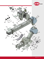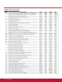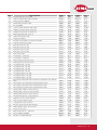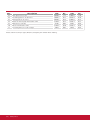
1
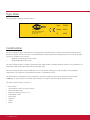
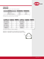
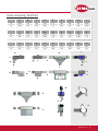
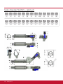
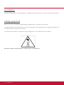
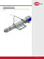
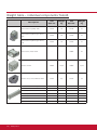
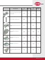
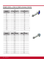
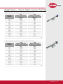
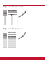
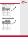
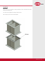
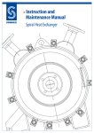
AGRO
Manual
Chain & flight conveyor
T44/T45
Version 70502.1
Contents
Contents..........................................................................................................................................2
Introduction.....................................................................................................................................4
EU Declaration of conformity ...........................................................................................................5
Conditions of use.............................................................................................................................6
General information.........................................................................................................................7
Delivery...................................................................................................................................7
Storage...................................................................................................................................7
Noise level measuring..............................................................................................................7
Type plate ..............................................................................................................................8
Construction............................................................................................................................8
Capacity..................................................................................................................................9
Technical specifications – power consumption ���������������������������������������������������������������������10
Drive station..........................................................................................................................11
Extensions.............................................................................................................................11
Tension section.....................................................................................................................12
Closed bottom section...........................................................................................................12
Scale drawing T44/T45..........................................................................................................13
Scale drawing T44/T45 for grain pit.......................................................................................14
Upon receipt .........................................................................................................................15
Warning labels.......................................................................................................................15
Foundation............................................................................................................................16
Lifting equipment..................................................................................................................16
Lifting instructions.................................................................................................................17
Weight table – individual components T44/T45���������������������������������������������������������������������18
Weight table T44/T45............................................................................................................20
Weight table T44/T45............................................................................................................21
Weight table T44 (gear motor)..............................................................................................22
Weight table T44 (pulley drive)..............................................................................................22
Weight table T45 (gear motor)..............................................................................................23
Weight table T45 (pulley drive)..............................................................................................23
Assembly.......................................................................................................................................24
Sealing..................................................................................................................................25
Closed bottom section/tension section����������������������������������������������������������������������������������26
Conveyor with intermediate outlet and side inlet������������������������������������������������������������������28
2 | www.jema.as
AGRO
.
.
.
Conveyor with inlet trough / 45˚ bend............................................. 29
Gear motor assembly...................................................................... 30
Fitting the motor and pulley drive................................................... 31
Extensions and inlet trough............................................................ 32
Chain.............................................................................................. 32
Chain and flight conveyor assembly................................................ 34
Potential adjustment ...................................................................... 35
Attachment ................................................................................... 36
Upstart .......................................................................................... 38
Conveyor stops – fault finding ....................................................... 38
Maintenance........................................................................................... 39
Gear motor..................................................................................... 39
Motor............................................................................................. 39
Pulley kit........................................................................................ 39
Chain.............................................................................................. 40
Rubber slats................................................................................... 40
Bearings......................................................................................... 40
Lubrication of bearings................................................................... 40
Closed bottom section and tension section..................................... 41
Drive station................................................................................... 41
Leaks............................................................................................. 41
Noise and vibrations....................................................................... 41
Disposal.................................................................................................. 42
Options/accessories................................................................................ 43
Outlet for drive station................................................................... 43
Shut-off valve................................................................................. 44
Extensions...................................................................................... 45
Intermediate outlet......................................................................... 46
Turnbuckle kit................................................................................. 47
Cover.............................................................................................. 48
Drypit............................................................................................. 49
Discharge box................................................................................. 49
Parts T44/T45......................................................................................... 50
Parts list T44/T45........................................................................... 52
www.jema.as | 3
Introduction
JJEMA AGRO A/S is a modern factory, which specializes in producing and delivering equipment for transport systems for
raw or cleaned grain, seeds and granulates.
Our current product range is the result of more than 50 years experience in machine development especially for the
agriculture in close collaboration with our customers – and our company is highly regarded in the industry due to the
quality and versatility of our products.
JEMA AGRO A/S conveyors and transport systems are compatible with ALL types of dryer- and silo systems.
Important!
Please read these instructions carefully before assembly and use.
4 | www.jema.as
EU Declaration of conformity
The manufacturer:
JEMA AGRO A/S
Kløservejen 2, Sahl
DK-8850 Bjerringbro
Tlf. +45 86 68 16 55
AGRO
Hereby declares that:
Product: Chain & flight conveyor
Type:T44/T45
Year of production: 2006
•
Conforms to the Machine directive 2006/42/EF with special reference to the directive appendix 1 regarding major health- and safety regulations regarding construction and production of the machines.
The following standards have been applied:
EN ISO 12100-1:2005
Basic terminology and methodology
EN ISO 12100-2:2005 Technical principles
EN 1050:1997
Principles for risk assessment
•
is in accordance with EMC-directive 04/108/EF of 15th December 2004 regarding electro-magnetic compatibility.
Director
Title
Jens-Peter Pedersen
Name
29.11.2010
Date
Signature
www.jema.as | 5
Conditions of use
JEMA AGRO A/S chain & flight conveyors T44/T45 have been constructed for transport of grain, granular materials and
seed mix.
•
The chain & flight conveyors T44/T45 must only be used for the product(s) specified in the contract.
•
The electrical connections must be done by a qualified electrician.
•
The chain & flight conveyors T44/T45 must be potential adjusted in accordance with the current local regulations
•
The chain & flight conveyor has been thoroughly controlled regarding maintenance, and a checklist has been drawn up containing regular cleaning- and maintenance intervals. If these intervals are not observed, the
JEMA AGRO conditions for a trouble-free operation cease to exist and the warranty will be invalid.
•
During installation, maintenance or repair the electric supply to the chain & flight conveyors must be
disconnected and secured against accidental reconnection.
•
The user manual must be kept / be available in close proximity to the chain & flight conveyor T44/T45
6 | www.jema.as
General information
AGRO
Delivery
The chain & flight conveyor is disassembled for shipment. Standard packing (pallet/wooden
boxes, grid boxes, etc.) Regarding the actual transport there are no specific requirements
apart from normal consideration.
The shipment includes the parts stated in the order confirmation.
Please read this manual carefully before installation and use.
Storage
There are no precautions regarding long-time storage.
After delivery the components must be kept in a suitable, dry storage area before
installation.
Noise level
A noise level test was conducted for the chain & flight conveyor. The level has been
measured in a distance of 1 m from the conveyor surface and at a height of 1.6 m from the
floor level. During the test the chain & flight conveyor was running unloaded, which is the
operational state of maximum noise level.
The measured noise level is below 70 dB
www.jema.as | 7
Type Plate
The type plated is fitted on the drive station.
Type:
JEMA AGRO A/S
Sahl, DK-8850 Bjerringbro
tlf. +45 86 68 16 55
www.jema.as
XXXXX
Model: XXXX
År:
XXXX
Construction
The chain & flight conveyor type T44/T45 is constructed by standard elements, which can be combined and easily integrated into all grain conveyor systems. It is characterized by a high capacity and compact dimensions. The chain & flight
conveyor is available in two versions:
•
Model A, closed transport chain system
• Model B adjustable inlet trough
The chain & flight conveyor is made of galvanized steel, which makes it perfectly suited for outdoor use. Furthermore it is
fitted with a high quality roller chain with riveted rubber slats.
The chain & flight conveyor can be fitted with one or several inlets, facing right or left according to the individual
requirements. The outlet can be operated by manually, or oprated by a motor.
The drive station is fitted with a tension mechanism, the chain & flight conveyor can be operated by drive pulleys
(1000 rpm) or a pinion gear motor, which can be fitted on the right or left hand side of the drive station.
The chain & flight conveyor consists of:
• Drive station
• Closed bottom section or tension section
• Chain with rubber slats
• Extensions from 0.125 m to 2.5 m.
• Intermediate outlet
• Inlet trough
• Side inlet
• Outlet
• Motor.
8 | www.jema.as
AGRO
Capacity
The table below shows the various density capacities:
Density
T44 (40 m3/h)
T45 (80 m3/h)
650 kg. pr. m3
26 t/h
52 t/h
700 kg. pr. m3
28 t/h
56 t/h
30 t/h
60 t/h
750 kg. pr. m (wheat)
3
Measured in cleaned, storable material at a power supply of 50 Hz
The capacity varies according to the nature of the material
Inlet trough adjustment
J
In opening
Capacity
t/h
Pulley drive with
motor 1.500 rpm
15
5
25
11
Gear motor
280 rpm
35
18
45
25
Pulley drive with
motor 1.000 rpm
20
10
35
16
Gear motor
180 rpm
50
23
65
30
T44
J
In opening
Capacity
t/h
Pulley drive with
motor 1.500 o/m
15
25
25
31
Gear motor
280 rpm
35
38
45
45
Pulley drive with
motor 1.000 rpm
20
30
35
40
Gear motor
180 rpm
50
50
65
60
T45
The capacity is measured at a density of 750 kg/m³.
Important! – The J dimension in the sketch is just for guidance.
Important! - Remember to adjust the inlet plates before starting.
J
www.jema.as | 9
Technical specifications – power consumption
Conveyor T44 - power consumption in kW:
Type
0-16m
17-23m
24-30m
31-41m
T44
2,2 kW
3,0 kW
4,0 kW
5,5 kW
Conveyor T45 - power consumption in kW:
Type
0-11m
12-15m
16-21m
22-29m
30-41m
T45
2,2 kW
3,0 kW
4,0 kW
5,5 kW
2 x 4,0 kW
Intake conveyor T44 - power consumption in kW:
Type
0-16m
17-21m
T44
2,2 kW
3,0 kW
Intake conveyor T45 - power consumption in kW:
Type
0-11m
12-15m
16-21m
T45
2,2 kW
3,0 kW
4,0 kW
Intake conveyor T45 - power consumption in kW with wide drive station:
Type
0-4m
5-8m
9-15m
16-21m
T45
2,2 kW
3,0 kW
4,0 kW
5,5 kW
Conveyor T44/T45 with 45° bend:
Height / Inclination
Length,
metres
1,72m. / 2,14m
T44/T45 kW
3,10
2,2
4,10
2,2
5,10
2,2
6,10
2,2
7,10
2,2
8,10
2,2
9,10
2,2
10,10
2,2
11,10
2,2
10 | www.jema.as
AGRO
Drive station
The drive station is delivered as a complete unit.
The outlet and motor are delivered separately.
Extensions
The extensions are available in various lengths: 2.5 m, 2.0 m, 0.25 m, 0.125 m.
Extensions with inspection doors are available in lengths of 2.5 m.
Inlet troughs are available in lengths of 2.0 m. with inspection door: 1.25 m, 1.0 m, and 0.5 m.
The elements can be combined to obtain any length with intervals of 0.125 m.
Extension
Inlet trough
www.jema.as | 11
Tension section
The tension section is supplied as a complete unit.
Closed bottom section
Closed conveyor bottom section.
12 | www.jema.as
AGRO
Scale drawing T44/T45
A
B
C
D
E
F
G
H
I
T44
Ø200
330
300
400
215
500
805
960
Ø200
T45
Ø200
330
300
400
215
500
805
960
Ø200
J
K
L
M
N
O
P
Q
R
T44
500
328
330
Ø200
580
190
190
Ø200
375
T45
500
328
330
Ø200
580
250
230
Ø200
440
S
T
U
V
X
Y
Z
Æ
Ø
T44
670
210
225
890
400
750
100
420
405
T45
730
210
285
890
400
750
100
420
405
J
H
D
C
K
E
B
G
F
L
A
M
I
O
R
U
P
S
T
Q
N
X
Z
V
Æ
Ø
Y
www.jema.as | 13
Scale drawing T44/T45 – grain pit
A
B
C
D
E
F
G
H
I
J
K
L
T44
150
225
340
215
500
328
330
Ø200
580
190
225
200
T45
165
225
405
215
500
328
330
Ø200
580
230
285
200
M
N
O
P
Q
R
S
T
U
V
X
Y
T44
100
420
405
300
385
690
775
190
430
400
300
400
T45
100
420
405
300
385
690
775
225
470
460
300
460
B A
i
E
F
C
D
G
H
J
K
L
M N
O
U
V
R
P
Q
T
14 | www.jema.as
S
X
Y
AGRO
Upon receipt
Please check that all parts and components are included in the shipment and check for
possible transport damages.
NB: Make sure that the relevant supplier documentation is attached. In case of missing
documentation, please contact JEMA AGRO A/S – remember to state the order no.
Remember all necessary safety equipment before installation.
Please read this manual carefully before assembly or installation work begins.
Warning labels
The chain & flight conveyor is fitted with warning labels.
Warning!
The covers and shields must
never be opened or removed,
when the
machine is working.
Warning!
Always keep hands away from
rotating augers/propellers.
www.jema.as | 15
Foundation
The chain & flight conveyor should be placed on a sufficiently hard, level surface that is able to carry the load in question.
Lifting equipment
Make sure to have the required SWL-approved lifting equipment/crane, required for the actual job.
The lifting equipment must be approved to carry the load in question. The load capacity for the individual components can
be found in “Parts list T44/T45” in this manual.
The total weight of machines is stated in the section “Weight table - chain and flight conveyor T44/T45”.
NB: Always make sure that nobody is standing under a suspended load.
16 | www.jema.as
AGRO
Lifting instructions
The drawing below shows how to lift the chain & flight conveyor using the attached
brackets.
Lifting point
X
MA
00
50
www.jema.as | 17
Weight table – individual components T44/45
Description
Part no.
Weight
kg
T45
Part no.
Weight
kg
Drive station for pulley drive
51577
36
52116
39
Drive station for pinion gear motor,
RHS
51583
36
52483
39
Drive station for pinion gear motor,
LHS
51585
36
52485
39
-
-
45041
42
Tension section
44095
12,61
45095
13,77
Elevator boot, closed without chain
51231
6,6
52231
7,3
Extension 2.5 m with inspection door
51012
35
52012
37
Extension 2.5 m.
51021
35
52021
37
Extension, 2.0 m
51022
28
52022
32
Extension, 1.0 m
51024
14
52024
16
Extension, 0.5 m
51025
7
52025
8
Extension, 0.25 m
51026
3
52026
5
Extension 1.25 m
51027
2
52027
3
Drive section, wide model
18 | www.jema.as
T44
AGRO
Description
T44
Part no.
Weight
kg
T45
Part no.
Weight
kg
Extension 0.5 m with side inlet d200
without chain
44130
10,5
45130
12
Chain complete, running metres
20028
2
40028
4
Trough kit with cover for 0.5 m inlet
trough
44024
12
45024
13
45° bend without chain with
sprocket
44060
30,50
45060
31,60
Intermediate outlet with 1,0 m
extension
44101
35,10
45101
37,20
Intermediate outlet without
extension
44100
23,96
45100
25,82
Outlethopper SK200 for Intermediate
outlet
44102
6,60
45102
7,08
www.jema.as | 19
Weight table – chain & flight conveyor T44/45
Complete with pinion gear motor and inlet trough.
Length,
metres
T44
Pinion gear motor
180 rpm
Kg.
T45
Pinion gear motor
180 rpm
Kg.
3,0
151,5
176
4,0
179,5
210
5,0
207,5
244
6,0
235,5
278
7,0
263,5
318
8,0
291,5
352
9,0
319,5
386
10,0
347,5
420
11,0
375,5
454
12,0
403,5
488
13,0
431,5
522
14,0
459,5
562
15,0
487,5
596
16,0
515,5
630
17,0
543,5
664
18,0
571,5
698
19,0
599,5
732
20,0
21,0
627,5
655,5
766
800
Complete with pulley drive and inlet trough.
T44
Motor 1500 rpm
pulley kit 71/355
Kg.
T45
Motor 1500 rpm
pulley kit 71/355
Kg.
3,0
151,5
176
4,0
179,5
210
5,0
207,5
244
6,0
235,5
278
7,0
263,5
318
8,0
9,0
10,0
291,5
319,5
347,5
352
386
420
11,0
375,5
454
12,0
403,5
488
13,0
431,5
522
14,0
459,5
562
15,0
487,5
596
16,0
515,5
630
17,0
543,5
664
18,0
571,5
698
19,0
20,0
599,5
627,5
732
766
21,0
655,5
800
Length,
metres
20 | www.jema.as
AGRO
Weight table – chain & flight conveyor T44/T45
Complete with pinion gear motor, intermediate outlet and side inlet
Length,
metres
T44
T45
Pinion gear motor
180 rpm
Kg.
Pinion gear motor
180 rpm
Kg.
4,0
159,6
182
5,0
177,6
206
6,0
195,6
230
7,0
213,6
260
8,0
231,6
284
9,0
249,6
308
10,0
267,6
332
15,0
363,6
457
20,0
453,6
577
25,0
548,6
708
30,0
638,6
828
35,0
739,6
941
41,0
847,6
1063
Complete with pinion gear motor, intermediate outlet and side inlet
T44
T45
Length,
metres
Motor 1500 rpm
pulley kit 71/355
Kg.
Motor 1500 rpm
pulley kit 71/355
Kg.
4,0
159,6
182
5,0
177,6
206
6,0
195,6
230
7,0
213,6
260
8,0
231,6
284
9,0
249,6
308
10,0
267,6
332
15,0
363,6
457
20,0
453,6
577
25,0
548,6
708
30,0
638,6
828
35,0
739,6
941
41,0
847,6
1063
www.jema.as | 21
Weight table –T44 (gear motor)
Complete with pinion gear motor, 45° bend and inlet trough.
Height / Inclination
1,63m. / 2,05m.
Length
in
metres
Motor
180 rpm
Kg.
2,86
215
3,86
243
4,86
271
5,86
299
6,86
327
7,86
355
8,86
383
9,86
411
10,86
439
Weight table –T44 (pulley drive)
Complete with pulley drive, 45° bend and inlet trough.
Height / Inclination
Length
in
metres
1,63m. / 2,05m.
Motor 1500 rpm
pulley drive 71/355
Kg.
2,86
215
3,86
243
4,86
271
5,86
299
6,86
327
7,86
355
8,86
383
9,86
411
10,86
439
22 | www.jema.as
AGRO
Weight table –T45 (gear motor)
Complete with pinion gear motor, 45° bend and inlet trough.
Height / Inclination
Length
in
metres
1,63m. / 2,05m.
Motor
180 rpm
Kg.
2,86
260
3,86
294
4,86
334
5,86
368
6,86
402
7,86
436
8,86
470
9,86
504
10,86
538
Vægtskema T45 (Kileremtræk)
Complete with pulley drive, 45° bend and inlet trough
Height / Inclination
Length
in
metres
1,63m. / 2,05m.
Motor 1500 rpm
pulley drive 71/355
Kg.
2,86
260
3,86
294
4,86
334
5,86
368
6,86
402
7,86
436
8,86
470
9,86
504
10,86
538
www.jema.as | 23
Assembly
Please check the foundation and the travel direction (location of inlet and outlet) before starting the assembly.
It is important to read these instructions carefully before starting the assembly.
Check that there is sufficient space available.
Attention!
Before starting the assembly work, check that the required safety equipment is at disposal, e.g. work gloves, safety
footwear, helmet, safety glasses and a lifeline, if necessary. This equipment is not included as standard.
24 | www.jema.as
AGRO
Sealing
All the joints must be sealed with a sealing compound in order to avoid dust and moisture
entering at the flange joints.
The sealer must be applied at the flanges inside the holes.
After sealing the joints must be bolted together.
Silicone
www.jema.as | 25
Closed bottom section/Tension section
Fit the extensions to the closed bottom section or to the tension section – remember that
the overlapping plate must be facing downward (see drawing).
Tension section
Closed bottom section
Overlapping plate
26 | www.jema.as
AGRO
Important!
It is important to fit a tube of min. 850 mm or another type of guard to the inlet and outlet
points to prevent entry of hands or fingers into the machine.
850 mm tube end
or guard
www.jema.as | 27
Chain & flight conveyor with intermediate outlet and side
outlet
2
1
Pos.
28 | www.jema.as
Description
1
Extension 0.5 m with side inlet
without chain
2
Extension 1.0 m with shut-off valve
with brush without chain
AGRO
Chain & flight conveyor with inlet trough / 45° bend
2
1
1
Pos.
Description
1
Inlet trough with return
channel without chain
2
45° bend without chain
www.jema.as | 29
Gear motor assembly
Fit the motor and gear on the drive shaft (see below drawing).
The engine can be fitted in parallel or traversely on the machine.
Important!
The bleed screw on the gear must always be fitted in the top position.
TF90B gear 4,0 - 5,5 kW
TF63B gear 2,2 - 3,0 kW
For maintenance of motor and gear: please see the attached supplier documentation.
30 | www.jema.as
AGRO
Fitting the motor and pulley drive
•
Start by screwing on the motor stand and then fit the internal pulley guard
•
Fit the small pulley on the motor shaft and tighten with a screw.
•
Fit the engine loosely on the stand with 4 bolts without tightening it, screw the clip bolt and tension
bolt on the motor stand, and then fit the large pulley on the drive station shaft and tighten it with a
screw (remember the Woodruf wedge).
•
Offset the motor in the slotted holes of the support, until the pulley sheaves are parallel. Tighten the
motor bolts.
•
Move the motor stand towards the conveyor by loosening the tension bolt, and fit the pulleys. Tighten
with the tension bolt and the clip bolt.
•
Finally fit the external pulley guard.
The belt tensioning is correct when the belt deflection is 10-15 mm (see drawing).
10-15mm.
Important!
The belt needs retightening after the first 24 hours, and then according to the maintenance schedule.
NOTE!
Do no use tools to force the pulleys onto the sheaves.
www.jema.as | 31
Extensions and inlet trough
The extensions/inlet trough must be fitted in a way that provides sufficient space for later assembly of the chain, as this
has to be done through the extension/inlet trough opening/access door.
Fit the extensions/inlet troughs as shown on the drawing (if available).
The conveyor must constantly be supported during the
fitting – see section “Attachment”.
Extension
Inlet trough
Chain
The conveyor chain is equipped with rubber slats, and the chain must be fitted before the drive station. Assemble the
chain with the chain connectors (see drawing) and check the length of the chain (the tension bolts on the drive station
must be loose) If required, the chain can be shortened with a thin chisel. Assemble the chain – use only new splits in the
connections. Tighten the chain with the bolts on the drive station, and make sure to have a few mm play at the bottom
sprocket. Retighten the chain after 30 min.
32 | www.jema.as
AGRO
Important!
When fitting and tightening the chain on machines with inclinations there must always be the same distance
between the slats (pos. A), and there must be one slat for each 4th. chain link.
www.jema.as | 33
Chain & flight conveyor assembly
Use correct and approved SWL-lifting equipment for the assembly.
Read the section “Upon receipt” before starting the assembly work.
If space allows the easiest way is to assembly the conveyor on the floor either in full length or in separate components.
Any troughs or extensions, fitted with inspection doors, must be equally spaced over the full length of the conveyor.
If troughs or extensions are fitted with an overlapping plate, the plate must be facing away from the drive station in the
driving direction.
Fit the extension with the tall transport channel facing downwards, and then fit the respective in- and outlets. Fit the
drive station and the bottom part. If inlet troughs are used, they must be fitted with a connecting flange.
Mount the gear motor or the pulley drive at the drive station. The gear motor can be fitted in a cross-machine direction.
The chain conveyor is mounted on the floor in a length between 5-8 meters. The chain in fitted as the last item in the
assembly. The easiest way to fit the chain is to remove the top plate in the drive station. The chains are delivered in 10
meter lengths with connecting links.
IMPORTANT!
Pull a rope or wire through all the extensions, both the lowest and the top side in order to mount the
chain later.
Place the chain correctly in the sprocket wheel and short up the chain in the in the desired length.
The chain is assembled and tightened via the bolts at the drive station or/ and the tightening section.
The chain is tightened until the rubber slats are standing vertical in the full length of the conveyor.
IMPORTANT!
Remember to remount all the inspection covers after assembling the chain.
Tension bolts
34 | www.jema.as
AGRO
Potential adjustment
The potential adjustment must be carried out according to the current regulations.
A label on the drive station indicates the point of the belt conveyor potential adjustment.
The label indicates the potential adjustment point for the belt conveyor.
Potential adjustment
www.jema.as | 35
Attachment
In order to obtain the maximum stability, it is important to secure the belt conveyor properly. There must be a distance of
maximum 5.0 m between the fixation points. If the distance is greater, it is necessary to use
wire suspention.
Regarding the wire suspension for conveyors, there are various
possibilities – see drawings below.
Wire suspension – double with side guides
MAX 5000
MAX 5000
4
1
3
MAX 5000
2
Wire suspension – single with side
guides
MAX 10000
Pos.
Description
T20
Kg.
T40
Kg.
1
Wire thimble for 8mm wire
92112
0,032
92112
0,032
2
Wire rope clips for 8mm wire
92113
0,032
92113
0,032
3
Wire 8mm (weight per m.)
92114
0,194
92114
0,194
4
Wire idler for 8mm wire
92115
0,400
92115
0,400
36 | www.jema.as
AGRO
Wire suspension – double
MAX 5000
MAX 5000
MAX 5000
4
1
3
2
Wire suspension – single
MAX 10000
Pos.
Description
T20
Kg.
T40
Kg.
1
Wire thimble for 8mm wire
92112
0,032
92112
0,032
2
Wire rope clips for 8 mm wire
92113
0,032
92113
0,032
3
Wire 8mm (weight per m.)
92114
0,194
92114
0,194
4
Wire idler for 8mm wire
92115
0,400
92115
0,400
www.jema.as | 37
Starting up
Before starting to work with the chain & flight conveyor, please check that:
•
All inspection doors are fitted
•
No work is carried out on/near the machine.
•
The motor rotation direction is correct.
•
All conveyor bolts are correctly fitted and tightened.
•
The chain is correctly fitted and adjusted.
•
The attachment and stability of the conveyor is correct.
•
Check after start that no joints are leaking.
•
If fitted, check for correct tension of the pulley.
Conveyor stops – fault finding
In case of stops, check first whether the conveyor is able to start again, when the relay has gone cold. If yes, the fault is
either caused by low adjustment of the relay or lack of motor capacity.
If the conveyor is still not able to start without being emptied of material, it must be checked whether the return tube
(downward passage) on the conveyor is filled with material in the first section (open the inspection door). In this case
the fault is due to blockage of the conveyor drain (drain tubes too small or insufficient slope) or caused by stops further
along in the transport system.
38 | www.jema.as
Maintenance
AGRO
Please see the maintenance summary and the attached supplier documentation for
cleaning- and maintenance intervals.
Warning!
•
During cleaning and maintenance work, the electric supply for the chain & flight
conveyor must be disconnected and secured against accidental reconnection.
•
After repair and maintenance the inspection doors and shields must be refitted before the work is continued.
Use original parts only
In case parts that original parts are not used, the warranty becomes void, and
JEMA AGRO A/S can no longer be held liable for the EU Declaration of conformity.
Gear motor
Check the gear as described in the attached supplier documentation.
Important!
Check that the bleed screw is fitted in the top position on the gear.
Motor
Bearing noise from the motor: please see the attached supplier documentation.
Motor inspection: please see the attached supplier documentation.
Retorque the motor as indicated in the maintenance summary. Please see the assembly
guidance for instructions.
Pulley kit
Check the belt tension intervals as indicated in the maintenance summary.
Check for cracks in the side of the belts. Replace if necessary.
Note!
Do not mix old and new belts.
www.jema.as | 39
Chain
Check that the chain tension is correct.
See drawing for correct procedure.
IMPORTANT! When tightening the chain, loosen the torque arm.
See inspection intervals in the maintenance summary.
Max 30°
Rubber slats
Defective or worn rubber slats must be replaced.
See the maintenance summary.
Bearings
Check the bearings for wear/play, and lubricate as described in the maintenance summary.
Check for wear/play by lifting up the shaft and control manually.
Make sure that there is no water in the pit, as this will damage the bearings in the drive station/bottom section.
Lubrication of bearings
Important!
It is extremely important to use the correct amount of grease, as too much will damage the sealing of the bearing, which
will result in leaks and subsequent overheating of the bearing.
Check the amount of grease per grease gun stroke.
40 | www.jema.as
AGRO
Closed bottom section and tension section
Lubricate and exchange the bearings as described in the maintenance summary.
Drive station
Lubricate and change the two drive station bearings as described in the maintenance
summary.
Leaks
All leaks must be repaired immediately.
Nose and vibrations
Stop the chain & flight conveyor immediately and identify the problem.
www.jema.as | 41
Disposal
The methods of disposal must comply with the current local regulations.
Warning!
The electric supply to the motor must be disconnected during the disassembly.
Disassemble the conveyor on the floor, if space allows, following the reverse order of the assembly procedure.
If the chain & flight conveyor is disassembled at the premises, start by detaching the motor. For conveyors with pulley
drive, the pulley must be removed first, then motor, the large pulley sheave and finally the guard.
The easiest way to remove the chain is to dismantle the joint at the bottom of the conveyor and then pull out the chain
through the bottom inspection door. Finally remove all extensions.
The chain & flight conveyor contains various materials that can be reused. All metal parts should be delivered to a recycle
industry.
42 | www.jema.as
AGRO
Options/accessories
Drive station outlet
Inclination from 0° to 10°:
B
1
A
Pos.
1
D
Description
Outlet trough for drive-/tension section 90°
T20
Kg.
T40
Kg.
44247
4,500
45247
5,000
Pos.
T20
T40
A
Ø200
Ø200
B
650
650
C
440
440
D
330
330
Inclination from 10° to 45°:
B
C
1
A
www.jema.as | 43
Options/accessories
Shut-off valve
1. Shut-off valve for drive-/tension section.
2. Shut-off valve with 2 end stops for drive-/tension section.
3. Shut-off valve for drive-/tension section with motor 0.12 kW and 2 end stops.
Pos.
Description
T44
Kg.
T45
Kg.
1
Shut-off valve for drive-/tension section
44026
7,0
45026
8,3
2
Shut-off valve with 2 end stops for drive-/tension section
44098
7,2
45098
8,5
3
Shut-off valve for drive-/tension section with motor and 2 end stops
44044
17,9
45030
19,2
44 | www.jema.as
AGRO
Extensions
1. Trough kit with cover for 0.5 m inlet trough
Pos.
1
Description
Trough kit with cover for 0.5 m inlet trough
T44
Kg.
T45
Kg.
44024
12
45024
13
www.jema.as | 45
Intermediate outlet
Extension 1.0 m with shut-off valve and brush without chain, can be combined with different
outlet troughs and control systems.
1
Outlet troughs
2
5
Control systems
4
3
Pos.
Description
T44
Kg.
T45
Kg.
1
Intermediate outlet with 1,0 m extension.
44101
35,10
45101
37,20
2
Outlethopper SK200 for intermediate outlet.
44102
6,60
45102
7,08
3
Manual pull for intermediate outlet.
45105
4
2 end stops fitted on intermediate outlet
88115
0,16
88115
0,16
5
Motor 0.12 kW with limit stop for intermediate outlet
45104
6,0
45104
6,0
46 | www.jema.as
45105
AGRO
Wire suspension
1
2
3
Pos.
Description
4
T44
Kg.
T45
Kg.
1
Wire suspension, single with 21 m wire for 10 m suspension
00046
25,0
00046
25,0
2
Wire suspension, double with 31 m wire for 15 m suspension
00047
32,0
00047
32,0
3
Wire suspension, single with 44 m wire and side guide for 10 m suspension
00048
38,0
00048
38,0
4
Wire suspension, double with 64 m wire and side guide for 15 m suspension
00049
43,0
00049
43,0
www.jema.as | 47
Cover
1. Cover for 1 m extension with outlet
2. Tarpaulin cover for drive station
Pos.
Description
T44
Kg.
T45
Kg.
1
Cover for 1 m extension with outlet
45132
30,0
45132
30,0
2
Tarpaulin cover for drive station with pulley kit
51090
3,0
51090
3,0
3
Tarpaulin cover for drive station with pinion gear motor
51091
3,0
51091
3,0
48 | www.jema.as
AGRO
DryPit
Separate fitting instructions attached.
Discharge box
Separate fitting instructions attached.
www.jema.as | 49
Parts T44/T45
36
10
37
59
38 39 40
11
29
26
32
34
70
12
35
27
8
7
4
3
2
6
31
71
5
1
14
33
69
28
28
30
68
24
42
25
12
13B
13A
41
13C
13D
13E
17
13F
22
15
19
16
18
20
21
23
50 | www.jema.as
13
AGRO
4
3
46
5
10
22
9
39
5
43
50
49
11
1
45
12
47
37
40
51
48
38
55
52
1
57
56
14
22
18
58
19
23
21
17
12
53
22
20
62
21
63
60
63
23
65
54
66
52
64
63 22
23
63
61
66
53
67
21
65
www.jema.as | 51
Parts list T44/T45
Pos.
T20
Kg.
T40
Kg.
Drive station without chain for pinion gear motor 2.2-5.5 kW, RHS
51583
36,00
52483
39,00
Drive station without chain for pinion gear motor 2.2-5.5 kW, LHS
51585
36,00
52485
39,00
Drive station without chain for pulley drive
51577
36,00
52116
39,00
2
Spacer d30 for drive station with pinion gear motor
51581
0,03
51581
0,03
3
Bearing UCF 206, 30 mm
85130
1,20
85130
1,20
4
Bearing plate for elevator head
51066
0,80
51066
0,80
5
Space for elevator head
20017
0,08
40017
0,13
6
Shaft d30 for elevator head with pinion gear motor
51580
2,00
52120
2,40
7
Feather key 8x7x80 mm
87066
0,04
87066
0,04
8
Feather key 8x7x40 mm
87065
0,07
87065
0,07
9
Sprocket 9 Z for elevator head d30
83026
1,80
83026
1,80
10
Shroud for elevator head
51564
1,70
52105
2,25
11
Adjustable intermediate plate for elevator head
51570
1,70
52108
2,20
12
44247
4,50
45247
5,00
81319
5,00
81319
5,00
13A
Outlet trough 90° for drive-/tension section SK200
Torque arm for pinion gear motor TF90B/TF63B parallel/crosswise of
extension
Rubber bush for torque arm Ø40/14 x 20 for pinion gear motor
91520
0,03
91520
0,03
13B
Torque arm, part for tightening plate
81326
0,50
81326
0,50
13C
Torque arm, part for pinion gear motor
81327
0,70
81327
0,70
13D
Torque arm, part for conical wheel gear, 90° RHS
81321-1
0,85
81321-1
0,85
13E
Torque arm, part for conical wheel gear, 90° LHS
81321
0,85
81321
0,85
13F
Bracket for Torque arm, TF63B
81330
0,54
81330
0,54
14
Extension 2.5 m with door, without chain galv.
51012
35,00
52012
37,00
Extension 2.5 m without chain galv.
51021
35,00
52021
37,00
Extension 2.0 m without chain galv.
51022
28,00
52022
32,00
Extension 1.0 m without chain galv
51024
14,00
52024
16,00
Extension 0.5 m without chain galv
51025
7,00
52025
8,00
Extension 0.25 m without chain galv
51026
3,00
52026
5,00
Extension 0.125 m without chain galv
51027
2,00
52027
3,00
15
Extension 0.5 m w/side inlet SK 200 without chain galv.
44130
10,50
45130
12,00
16
Elevator base closed without chain galv.
51231
6,60
52231
7,30
17
Inspection door for tension section/closed elevator base
20005
0,53
40005
0,74
18
Bush for elevator base, short d26 x 25/d26 x 58
20038
0,02
40038
0,06
19
Bush for elevator base, long d26 x 48/d26 x 78
20039
0,05
40039
0,08
20
Sprocket 8 Z for elevator base d25
20036
1,10
20036
1,10
21
Shaft for tension end / bend
20230
0,70
40230
1,00
22
Feather key 8x7x30mm
87079
0,02
87079
0,02
23
Bearing with flange UCF/PFL, 205, 25 mm
85100
0,30
85100
0,30
24
Intermediate outlet without extension
44101
35,10
45101
37,20
25
Outlethopper SK200 for Intermediate outlet
44102
6,60
45102
7,08
26
Nonfric wear rail for 1.0 m extension with outlet
91503
0,14
91503
0,14
27
Drive shaft for intermediate outlet
45104-2
0,12
45104-2
0,12
28
Roller for pull, intermediate outlet
45100-10
0,03
45100-10
0,03
29
Brush for 1.0 m extension with outlet
44128
0,05
45128
0,07
30
Slide rail for intermediate outlet, PEHD1000
44100-8
0,03
45100-8
0,03
1
13
Description
52 | www.jema.as
AGRO
Pos.
Description
T20
Kg.
T40
Kg.
37014
0,04
37014
0,04
45104-3
0,15
45104-3
0,15
81189
5,86
81189
5,86
Switch with gear FR 531-M2
88004
0,08
88004
0,08
Key 5x5x20mm
87061
0,01
87061
0,01
36
Cover for 1.0 m extension with outlet
45103
15,60
45103
15,60
37
Crimped connector link for chain 555
87103
0,10
87103
0,10
38
Straight connector link for chain 555
87102
0,10
87102
0,10
39
Rubber flap with plate and bolt
20171
0,10
40171
0,10
40
Chain running metres kpl.
20028
2,00
40028
4,00
41
Suspension bracket
00081
3,00
00081
3,00
42
Hoisting hook bracket for suspension bracket
00083
1,00
00083
1,00
43
Shaft for elevator head d30
20016
1,70
40016
2,00
45
Pulley kit, 2 grooves d24
52111
18,0
52111
18,0
45
Pulley kit, 2 grooves d28
52112
20,0
52112
20,0
45
Pulley kit, 3 grooves d28
52113
25,0
52113
25,0
45
Pulley kit, 4 grooved d38
52114
28,0
52114
28,0
46
Motor stand, large
51068
3,50
51068
3,50
47
V-belt AX 54 – 1372 mm
84254
0,15
84254
0,15
47
V-belt AX 56 – 1452 mm
84256
0,15
84256
0,15
48
Internal guard for elevator head
51069
2,00
51069
2,00
49
External guard for elevator head
51070
3,20
51070
3,20
50
V-belt pulley A71 2 gr. d24
82081
0,70
82081
0,70
50
V-belt pulley A71 2 gr. d28
82113
0,60
82113
0,60
50
V-belt pulley A71 3 gr. d28
82177
1,00
82177
1,00
50
V-belt pulley A71 4 gr. d38
82179
1,00
82179
1,00
51
V-belt pulley A355 2 gr. d30
82131
8,50
82131
8,50
51
V-belt pulley A355 3 gr. d30
82193
10,80
82193
10,80
51
82235
15,00
82235
15,00
44014
48,00
45014
52,00
52
V-belt pulley A355 4 gr. d30
Inlet trough 2.0 m with return channel and inspection door without
chain
Inlet trough 1.25 m with return channel without chain
44011
32,00
45011
34,00
52
Inlet trough 1.0 m with return channel without chain
44012
24,00
45012
26,00
52
Inlet trough 0,5 m with return channel without chain
44013
12,00
45013
13,00
31
Sprocket wheel 12 Z 1/2” Ø20
32
Chain for intermediate outlet, 833mm
33
Pinion gear motor RMI 28
34
35
52
53
Adjuster plate 1.0 m for return channel
44173
2,25
44173
2,25
53
Adjuster plate 1.25 m for return channel
44172
2,80
44172
2,80
53
Adjuster plate 0.5 m for return channel
44174
1,10
44174
1,10
54
Transition flange inlet trough/extension
44008
2,00
45008
2,00
55
Inspection door for return channel
44170
0,85
45070
0,85
56
Tension section without chain
44085
11,00
45085
12,50
57
Cover plate for tension station
44088
1,14
45088
1,53
58
Bend 45° without chain with sprocket.
44031
29,26
45031
31,6
60
Welded middle section for 45° bend
61
Shroud for 45° bend
62
Return flow gear 45° - 90° bend
63
Spacer d30x32,5/d30x66
64
Sprocket 7 Z welded kpl. d25
44032
5,60
45032
7,10
44031-3
0,27
45031-3
0,38
83006
5,00
83006
5,00
44060-6
0,03
40008
0,07
20034
0,73
20034
0,73
www.jema.as | 53
Pos.
Description
T20
Kg.
T40
Kg.
65
Gable plate for 45° bend
44060-2
1,12
45060-2
1,50
66
Assembling plate for 45-90° bend
51060-9
0,13
52060-9
0,20
67
Wearing plate for 45° bend
44060-3
0,28
44060-3
0,28
68
Bracket for manual pull, intermediate outlet
45105-1
0,15
45105-1
0,15
69
Wirelock for 5 mm wire
70
Wire for intermediate outlet
71
Connecting link 1/2” x 3/16” straight
92105
0,02
92105
0,02
45105-2
0,20
45105-2
0,20
37016
0,01
37016
0,01
Please state the conveyor type (T44/T45) and spare part number when ordering.
54 | www.jema.as
AGRO
www.jema.as | 55
JEMA AGRO A/S
Kløservejen 2, Sahl, DK-8850 Bjerringbro, Denmark
Tel.: +45 8668 1655, Fax: +45 8668 0074
www.jema.as