1
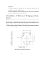
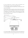
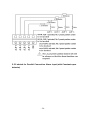
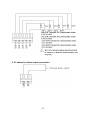
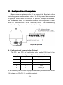
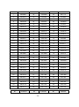
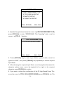
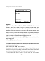
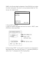
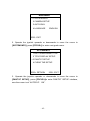
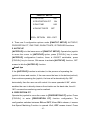
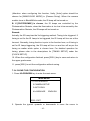
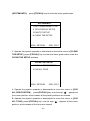
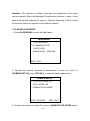
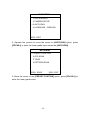
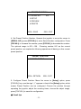
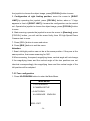
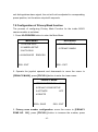
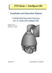
IR High Speed Dome Camera User’s Manual PTZ Cameras http://www.securitycamera2000.com ● Please read the manual carefully before installing and using the unit. ● Table of Contents I. Introduction ------------------------------------------------------------------------3 II. Technical Data --------------------------------------------------------------------3 III. Characteristics ------------------------------------------------------------------4 IV. Description of Functions -----------------------------------------------------5 V. Installation and Connection of IR High-speed Dome Camera ---- 7 5.1 Outer shape and dimension of the unit--------------------------------7 5.2 Preparation for the installation -------------------------------------------7 5.3 Installation of Wall-mount IR High Speed Dome Camera------------9 5.4 Installation of Pendant-mount IR High Speed Dome Camera------10 5.5 Connection of the cables for alarm in and out -----------------------11 VI. Configuration of the system--------------------------------------------------11 6.1 Configuration of Communication Protocol-------------------------------11 6.2 Configuration of Baudrate----------------------------------------------------11 6.3 Configuration of Address-----------------------------------------------------11 VII. Configuration and Operations through the OSD Menu-------------11 7.1 Basic Operation --------------------------------------------------------------15 7.2 Table for all Configuration and Operations through OSD Menu---17 7.3 Configure the information of the system --------------------------------18 7.4 Configure the parameter of the camera module-----------------------23 7.5 Configuration of the Auto Running----------------------------------------24 7.6 Configuration of Language--------------------------------------------------29 7.7 Configuration of Alarm function--------------------------------------------29 7.8 Configuration of Clock function--------------------------------------------30 7.9 Configuration of Privacy Mask function-----------------------------------34 VIII. Configuration and operation of the functions directly through the keyboard---------------------------------------------------------------------------------35 VIV. Simple Trouble Shooting Table---------------------------------------------36 -1- Important Safeguards 1. During the course of transportation and storage, the product should be avoided from incorrect operations such as heavy pressing, strong vibration, soaking etc, which may cause damage to the unit. 2. The product is designed for wall-mount and pendant-mount installation, it can not be installed upside-down. And the module should be handled properly so as not to bring about mechanical problems affecting the integrative functions of it. 3. Do not let any foreign objects or liquid infiltrate into the unit, which may damage the machine. 4. Please follow all electrical standards for safety when it is being connected and adopt the particular power supply which is provided with the unit. The product’s RS-485 and video signal adopt TVS-class lightning damage preventing technology, which can effectively prevent such pulse signal damage caused by lightning under 500W or electric surge. RS-485 and video signal should be kept enough distance from high voltage equipments and cables when they are in transmission, and necessary steps should be taken to prevent lightning damage or power surge. 5. No matter the unit is runing or not, the camera should never be aimed at the sun or object with extremely bright light. Otherwise, the camera’s CCD might be permanently damaged. 6. There are no parts inside the unit which can be repaired by the users themselves. When mechanical problems arise, do not be in a haste to do any repairing, please refer to the User’s Manual to find the trouble. If causes can not be located, please refer servicing to qualified professionals. All servicing must be done by authorized personnel. -2- I. Introduction Adopting latest technological achievements and cutting-edge manufacturing techniques, the IR High Speed Dome Camera is created with many years of accumulated experience. Equiped with a high performance DSP camera with zooming lens, integrating built-in Pan/tilt, digital decoder and extraordinary IR lamps, it represents the future trend of hi-tech monitoring products. The unit is capable of rapid positioning, consecutively tracing and scanning, which realizes all-directional monitoring. The unit can automatically adapt to ambient brightness and object distance. Its digital control and elegantly simple design maximally reduces the connection between differnent parts in the system, which improves the reliability of the system and facilitate the installation and maintenance. Driven by a stepper electric motar, the unit runs smoothly, reacts quickly and locates positions accurately. At the same time, the unit has multi intelligent functions such as: left & right scan, pattern scan, tour, Privacy Mask, alarm function etc. The IR lamp of the IR High Speed Dome Camera adopts the latest LED Array technology, LED Array has higher brightness, longer visible distance, more evenly distributed light field and much longer lifespan, with which the night-vision effect is greatly improved. Based on the above characters, this IR High Speed Dome Camera is further equiped with powerful OSD menu with multi input modes, which further facilitates all kinds of operations. At the same time, built-in highly accurate clock enables multiple orders to be automatically carried out at the time set, which can meet different demands from the customers. With various performances, this type of IR High-speed Dome Camera can be applied in every walk of life to monitor moving objects in large areas, such as monitoring smart buildings, bank, city streets, power system, airports, bus/railway stations etc. -3- II. Technical Data Power Supply DC15V(4A) (The adaptor should be connected within 2 meters from the IR High-speed Dome) -30°C~+60°C Working temperature Relative Humidity 10-90% Power Consumption Communication Protocol 35W PELCO_D / PELCO_P / PELCO_D1 Communication Method RS485 bus cable Communication 1200/2400/4800/9600bps Baudrate Address range of Speed 1~255 Domes Manually 0.5°~120°/S controlling Panning Speed Range of Pan/tilt Pan 360°endless, tilt 0°~+90° Auto flip function Auto-flip when vertical 90° Speed Auto-control as per the changing of The pan/tilt can automatically adjust the running speed following the change of the zoom ratio zoom ratio OSD Menu 4 input modes, all the functions of the pan/tilt and the camera module can be oprated through the OSD menu Preset Position number Left & Right scan 128 The beginning and the end point free to be set, 3 grades of speed (low, medium and high) optional -4- 360°Scan Vertical angle free to be set, 3 grades of speed (low, medium and high) optional Tour Group 4 groups, 16 preset positions for 1 tour group, dwelling time at each preset position can be set Pattern Scan number 4 Privacy 8 Mask Zone number Idle Time functions Alarm Functions IR lamp The function to be carried out in idle time can be configured, including invoking preset position, Left&Right scan, running tour etc 4 channels in, 1 channel out 4 groups, made up of LED Array, 150m visible distance at night, the number of the groups of the IR lamps to be turned on is intelligently controlled by the distance the camera module is monitoring, the farther it is monitoring, the more groups of IR lamps are turned on. IR light triggering control Triggered by photosensitive resistor / triggered by camera module (IR Lamp turned on when camera module turns to Black & White mode), altogether 2 methods Protection Grade IP66 Lightening-proof 2 grades anti-lightening design, 3 groups protecting point (video, communication and power) Weight 5.6Kg -5- III. Characteristics The cover is constructed with aluminum alloy, which ensures compact structure, high shielding strength and excellent heat-dispersion effect. The lower part of the unit is designed as exposed, which effectively solve the heat-dispersion problem for the camera module and the IR lamps etc parts. The Main Part, the Camera Module and the IR lamps are designed as isolated cover-shielding, which ensures not only good heat-dispersion effect but also water-proof effect and high reliability. Latest LED Array technology is adopted for the IR lamp, LED Array has higher brightness, longer visible distance, more evenly distributed light field and much longer lifespan. Driven by a stepper electric motar, the unit runs smoothly, reacts quickly and locates positions accurately. In-built module programme can automatically identify different camera modules including SONY, HITACHI, LG, JCO etc. Other camera programmes can also be added as per the requirement of the customers. Day&night IR-sensible camera module equiped inside. In the daytime, it is in color mode, the image is vivid; at night, it turns to Black&white mode, the image is crisp. Thus, all day long (24hours) monitoring is realized. Adopting full-functional high-performance DSP design, performance stable Multiple protocol and baudrate supported, high compatibility. -6- EEPROM data storing method adopted, so that the internally saved data will not lose when power off Powerful OSD Menu: 4 kinds of input methods. All the functions of the Pan/Tilt and the Camera Module can be configured and run through OSD menu. 128 preset positions for accurate location, 1 Left & Right scan, 4 tours, 4 pattern scan, 8 privacy mask zones. Support Idle Time function: According to actual requirement, the user can configure the function that the IR High-speed Dome Camera should carry out in idle time. The functions that can be set as Idle Time function includes Invoking Preset Positons, Left & Right scan, Tours etc. Support wire alarm function, 4 channels in, 1 channel out Memory recalling function once power on after power off IV. Description of Functions 1. IR Lamp The latest LED Array technology is adopted for this IR High Speed Dome Camera. LED Array is highly integration of traditional LED. Comparing with traditional LED, it has some advantages as below. A. Higher brightness: Since LED Array is integration of LED, the brightness and the viewing distance are greatly increased. B. Longer lifespan, due to the difference of the transparent material and the heat-dispersion effect, the lifespan of the LED Array is about 10 times as the traditional LED. C. More evenly distributed light: The half-intensified beam angle of the traditional LED is about 10°, well it is 10°-120°(variable angle) for LED Array, -7- which together with multi-angle disposal make the light evenly distributed and can light the whole room. rd For this unit, the latest 3 generation IR LED Array technology is adopted, st campared with the 1 and 2 nd generation IR LED Array, it has advantages as below: A. The light giving out efficiency is much higher. The latest technology is rd adopted for the 3 generation IR LED Array, under the same power consumption, the brightness is 2.5~3 times as the previous LED Array. At night, the visible distance is up to 150m or so. B. The heat produced is much less when the IR lamp is turned on. Since the rd light generating efficiency of the 3 generation IR Led Array is much higher, under the same power, less power is turned into heat and wasted, thus the lifespan of the IR Lamp is much longer. 2. Whole-day (24 hours/day) monitoring The camera module inside is IR sensitive with IR-cut. In the daytime, the image is color and vivid. Well, at night, it turns to B&W, at the same time, the IR lamps will be turned on, which ensures the image crisp. Therefore whole-day (24 hours) monitoring is realized. 3. OSD Menu Operation All the functions of the pan/tilt and the built-in camera module can be conveniently configured and carried out through the OSD menu. These functions include: Preset Positions, Tours, Pattern Scan, Left & Right Scan, Privacy Mask, Alarm, Language Choosing, and the configuration of the parameters of the Camera Module etc. The user can also edit the title of the IR High-speed Dome Cameras and the preset positions through multiple Input Modes, so that the titles are easier to be remembered and identified. The above functions make the IR High-speed Dome Camera really realize intelligent control and in-time monitoring. -8- 4. Trace the Target The users can control the movement of the unit by operating the joystick of the keyboard so that they can trace the moving object or change the monitoring area. The angle of view or the size of the image of the object can be changed through adjusting the focal length. In the default Auto-focus, Auto-Iris state, following the movement of the unit, the lens will quickly adjust itself to get clear image according to the change of the object. 5. Automatic Adjustment of Focal Length/Movement Speed When the focus is long and in the mode of manual adjustment, due to the high sensitivity of the IR High-speed Dome Camera, even the slightest movement of the joystick would make the image move quickly, which causes image losses. Based on human design, the IR High-speed Dome Camera can automatically adjust the horizontal and vertical moving speed of the pan/tilt according to the current focal-length, which makes the manual target-tracing operation much easier. 6. Configure and Invoke Preset Positions The preset position function works in this way: the IR High-speed Dome Camera stores the data of the pan/tilt angles and lens focal-length in current state; when needed, invoke these data, then promptly move the pan/tilt and camera module to the corresponding position. Through the OSD menu, the user can quickly and conveniently configure, invoke, delete the preset positions and edit the title of the preset positions. When the user invokes the preset position through the OSD menu, the unit will move to the preset position promptly, at the same time, the title of the preset positon editted by the user will be shown. The unit supports 128 preset positions. 7. Automatic Tours -9- The automatic tour function is a built-in function of the IR High-speed Dome Camera. Through beforehand programming, the user can arrange the preset positions into the automatic tour in the desired order. When it’s needed to run the tour, operating through the OSD menu, the user can make the IR High-speed Dome Camera automatically move as per the order of the preset positions configured in the tour with preset time intervals. ● The staying time at each preset position can be configured. ● Altogether 4 tours can be configured with the unit. ● Sixteen preset positions can be stored in one tour. 8. Left & right Scan Left/right limiting positions can be conveniently set through OSD menu. After configuring well, the user can run the left/right scan directly through the OSD menu, then the IR High-speed Dome Camera will automatically run horizontally between the left limiting position and the right limiting position, at the preset speed. 9. 360°Scan 360°endless scan is supported. When running 360°scan, the unit will rotating endlessly. There are low, medium and high 3 grades optional for the running speed of the 360°scan. 10. Pattern Scan The unit can store the user’s operating track and invoke it when necessary. A 4-minutes operation is acceptable to be stored for one Pattern Scan track. Altogether 4 Pattern Scan tracks can be stored in this unit. 11. Privacy Mask Within the monitoring range, if some privacy zones should be shielded from being monitored, some mask zones can be set within the monitoring - 10 - image. Altogether 8 Privacy Mask zones can be set in the unit. 12. Alarm Function The user can set the key areas as alarm points. Through the linkage with the external-connected detector, once there is alarm signal transmitted to the unit, the unit will promptly adjust the camera module to shoot the alarm point, at the same time, it will output alarm signal through the alarm output port. 13. Idle Time Function Users can set the function that is to be carried out in idle time as the Idle Time Function. If the user exit the OSD menu after finishing with other operations, and if the IR High-speed Dome Camera is in still state without running, then after a period of time during which nobody operates the unit, the unit will automatically begin to carry out Idle Time Function that is configured in advance. The functions that can be set as Idle Time Function include invoking preset position, running left&right scan, running tour etc. The length of the period of time after which the Idle Time Function is to be carried out can be set, the range is 1~240minutes. 14. Memory recalling function once power off The unit has memory recalling function when power is off. If the unit is running preset position, left & right scan, 360°scan, auto tour etc functions when the power is off, then once the power is on, the unit will automatically resume the ever-running functions after finishing self-checking 15. Camera module Lens Control Users can adjust the Focal-length through controlling the keyboard to get panoramic view or close view that they desire. Focal Length Control Users can adjust the Focal-length through controlling the keyboard to get - 11 - panoramic view or close view that they desire. Focus Control The system takes automatic focus as the default. While moving, the camera module can automatically focus on the center of the object view to get clear image. Under special circumstances, the user can manually adjust the focus to achieve desired image effect. ● Manual focus can be realized through controlling the keyboard or matrix. For details, please refer to the operation manual of the controlling keyboard or matrix. ● In the state of manual focus, the user can control focal–length to make the lens focus on objects. If the IR High-speed Dome Camera is configured to resume auto-focus upon joystick operation, when there is operating on the joystick, the IR High-speed Dome Camera will automatically focus. If a period of time is configured for auto-focus resuming, once there is no controlling order received, after the period of time, the IR High-speed Dome Camera will resume auto-focus. Under the following circumstances, the camera module can not carry out auto-focus: ● When the object is not in the center of the view. ● When simultaneously observe a far object and a near one, clarity for both of the images can not be guaranteed at the same time. ● When observing objects with extreme brightness, such as neon lights, spotlight, etc ● When the object is behind the glass with water drops or dust ● When the object moves very fast ● When the object is large-sized and drab, such as wall - 12 - ● When the object is too dark or fuzzy Iris Control ● The system takes automatic-iris as the default. The iris can automatically sense the change of the environmental light and make quick adjustment, so that the brightness of the image is stable. ● The user can manually adjust the iris through controlling the keyboard to obtain desired brightness for the image. Automatic Back Light Compensation (BLC) Automatic Back Light Compensation can be realized via district dividing. In extremely bright background, the camera module can compensate the brightness of the relatively dark objects, while adjust the light of the bright background, avoiding that the whole image is too bright to watch due to the too high brightness of the background while the object is too dark to be distinguished, so that clear image can be got. Automatic White Balance According to the ambient brightness, the camera module can automatically adjust the White Balance to re-display the real colors. - 13 - V. Installation and Connection of the IR High Speed Dome Camera 5.1 The outer shape and dimension of IR High Speed Dome Camera: The outer shape and dimension of IR High Speed Dome Camera 5.2 Preparation for installation 1. Installation should be carried out by professional personnels as per relative regulations lest there is any problem. 2. Check if the accessaries with the unit are complete. Confirm if the applying site and the installing method of the unit is the same as required. 3. A set of unit consists of bracket, housing, module, adaptor, installing - 14 - screws etc. 4. Before leaving the factory, the unit has been tested well for installation, users can install directly. 5. Before installation, please read carefully the instruction of installation in the User’s Manual enclosed with the unit. 5.3 Installation of Wall-mount IR High-speed Dome Camera Attention: The wall for the selected installation location must be firm without peeling. To avoid quivering images resulting from unstable installation, make sure the place for installation can sustain five times the total weight of the IR High-speed Dome Camera, the bracket and the base. A. Use the bottom installation board of the bracket as template and draw the positions of the installing holes on the desired wall locus; Wall Bracket Installation Dimensions - 15 - B. Use an electrical drill to make four holes for M6 screws on the above-drawn positions, and drive in the expansion M6 screws; C.Fix the installation board of the bracket firmly on the wall with four M6 screw nuts and washers. D. Push the power cable, communication cable and video cable through the bracket tube, then push the installing port on the top of the outer housing into the installing hole of the bracket, tighten the 3 M6 screws and fix well. Make sure the M6 screws just fit in the screw slot of the installing port of the housing. (See the picture below) E. Put the power adaptor into the wall bracket and pin the power adaptor with the adaptor pinning board, lest the power adaptor slides out. (See the figure - 16 - below) Attention: The adaptor equiped can only be placed indoor or in water-proof box or other water-proof spaces, it can not be placed directly outdoor, otherwise water may seep in and damage the adaptor. F. Put up the wall bracket assembled with IR High-speed dome on the ancillary hooks: Pull the power cable, video cable and controlling cable out through the wire-out-going hole of the bracket, then put the assembled on the two corresponding pegs on the installed peg-board, then push the bracket downward until it locks in place. Make sure the wall bracket is well fixed with the installation board, then direct the screw on the bracket to the corresponding hole on the lower part of the installation board and tighten the screw. - 17 - 5.3.2 Connection of Exterior Cables Cable Power cable Application Connecting Objects Remarks power supply for IR Inner the unit dome--- High-speed positive, outer negative power supply adaptor 485 cable Controlling the IR IR High-speed dome Green High-speed --- controlling device white(Negative) (Positive), IR High-speed dome Inner ---monitoring device negative Black cable Dome Video Cable video signal Earth Connecting the IR High-speed dome connecting earth for --- the earth port lightening proof 5-strand Alarm input cable positive, Detctor--- Black (Alarm IR High-speed dome public terminal) outer input Yellow (the 1st channel alarm input) Green (the 2nd channel alarm input) - 18 - Blue (the 3rd channel alarm input) White (the 4th channel alarm input) 2-strand Alarm output cable IR High-speed Brown (alarm output dome--- public terminal) alarm bell Grey (alarm output terminal) ◆ When connecting, make sure the polarity of RS485 controlling cable is correct: ◆ A: RS485 positive, B: RS485 negative. If wrongly connected, the IR High-speed Dome Camera will be out of control. 5.3.3 a Switch on Power Make sure the polarity of plugs, sockets and the connection of cables is correct, then switch on power b The IR High-speed Dome Camera begins to do the self-check: it moves pan 360°, tilt 90°, then moves to its original position, then zooms in and zooms out once. Through the self-check, the unit checks the mechanical moving performance of the pan/tilt, the electrical performance of the controlling system, the controlling of the camera module. After the IR High-speed Dome Camera finishes self-check, it stays at the original position and is ready to receive controlling instructions. c Use controlling device to control the IR High-speed Dome Camera, checking whether it can perform the functions of the pan/tilt and the lens of the camera module. If not, please check the configuration of communication protocol, Baud rate and address, and the connection of 485 controlling cable. - 19 - 5.4 Installation of Pendant-mount IR High-speed Dome Camera 5.4.1 Installation of Pendant-mount Bracket Remarks: The ceiling for the selected installation location must be firm without peeling. To avoid quivering images resulting from unstable installation, make sure the place for installation can sustain five times the total weight of the IR High-speed Dome Camera, the bracket and the base. A Use the bracket as template and draw the positions of the installing holes on the desired ceiling locus; B Use an electric drill to make three holes for M6 screws on the above-drawn positions, and drive in the special M6 screws; C Push the power cable, communication cable and video cable through the bracket tube, then push the installing port on the top of the outer housing of the unit into the installing hole of the bracket, tighten the 3 M6 screws and fix well. Make sure the M6 screws just fit in the screw slot of the installing port of the housing; D Put the power adaptor into some installing box, fix the adaptor well lest it slides out. Attention: The adaptor equiped can only be placed indoor or in water-proof box or other water-proof spaces, it can not be placed directly outdoor, otherwise water may seep in and damage the adaptor E Pull the power cable, video cable and controlling cable out through the cable slot of the bracket, leaving long enough cables for connection; F Fix the bracket firmly on the ceiling with three M6 screw nuts and washers. - 20 - 5.4.2 Connection of Exterior Cables Cable Power cable Application Connecting Objects Remarks power supply for IR Inner the unit dome--- High-speed positive, outer negative power supply adaptor 485 cable Controlling the IR IR High-speed dome Green (Positive), High-speed --- controlling device white(Negative) IR High-speed dome Inner ---monitoring device negative Black cable Dome Video Cable video signal Earth Connecting the IR High-speed dome connecting earth for --- the earth port lightening proof 5-strand Alarm input cable positive, Detctor--- Black IR High-speed dome public terminal) (Alarm outer input Yellow (the 1st channel alarm input) - 21 - Green (the 2nd channel alarm input) Blue (the 3rd channel alarm input) White (the 4th channel alarm input) 2-strand Alarm output cable IR High-speed Brown (alarm output dome--- public terminal) alarm bell Grey (alarm output terminal) ◆ When connecting, make sure the polarity of RS485 controlling cable is correct: ◆ A: RS485 positive, B: RS485 negative. If wrongly connected, the IR High-speed Dome Camera will be out of control. 5.4.3 a Switch on Power Make sure the polarity of plugs, sockets and the connection of cables is correct, then switch on power b The IR High-speed Dome Camera begins to do the self-check: it moves pan 360°, tilt 90°, then moves to its original position, then zooms in and zooms out once. Through the self-check, the unit checks the mechanical moving performance of the pan/tilt, the electrical performance of the controlling system, the controlling of the camera module. After the IR High-speed Dome Camera finishes self-check, it stays at the original position and is ready to receive controlling instructions. c Use controlling device to control the IR High-speed Dome Camera, checking whether it can perform the functions of the pan/tilt and the lens of the camera module. If not, please check the configuration of communication - 22 - protocol, Baud rate and address, and the connection of 485 controlling cable. 5.5 Connection of the cables for alarm in and out Connect the alarm cables according to the sketch below. Once distinguishing the alarm signal coming in, the speed dome will immediately act as per the process set before, it will start the camera, display the image of the alarm zone on the monitor, adjust the speed dome to the alarm point, and monitor the preset position, record what happens at the alarm zone as soon as possible. Connection of the alarm cables as the sketch below: Attention: a. Alarm input must be ON/OFF input signal, any other types of input signal(such as power voltage etc) is possible to damage the unit. When there are alarm signals from multi channels, the unit will respond to them one by one, the interval is 3 seconds. b. Once there is alarm signal coming in, the unit will not respond to ―Scan‖ , ―Cruising‖ etc functions. Manual operation is needed to restore ―Scan‖ , ―Cruising‖ etc functions. c. For the input terminals which are not connected with detectors, 2.2KΩ risistor must be connected, otherwise the speed dome will thinks that there is alarm signal coming in, thus the alarm output is always on. 5.5.1 sketch for Series Connection Alarm input (with Constant-closed detector) - 23 - 5.5.2 sketch for Parallel Connection Alarm input (with Constant-open detector) - 24 - 5.5.3 sketch for Alarm output connection - 25 - VI. Configuration of the system Before power on, please confirm if the protocol, the Baud rate of the controlling system and the address code of the IR High-speed dome camera is right (the factory default is: Pelco_D for protocol, 4800bps for baudrate, 001 for address code). You must make sure that the configuration of them must be identical to that of the controlling device. The corresponding switches for configuration is shown in the following figure: 6.1 Configuration of Communication Protocol The DIP-1 and DIP-2 of the 4-button switch on the PCB board is for communication protocol configuration. Please refer to the following table: NO. 2 1 PROTOCOL 1 0 0 PELCO_D 2 0 1 PELCO_P 3 1 0 NEW 4 1 1 PELCO_D1 If the controlling device could only support the preset position numbers below 128, please use PELCO_D1 controlling protocol. - 26 - 6.2 Configuration of Baud Rate DIP-3 and DIP-4 of the 4-button switch on the PCB board is used to configure Baudrate of communication, the default configuration is 4800BPS. Following table shows states of coding switches and cosrresponding Baudrate. No. 43 Baudrate 1 00 1200 BPS 2 01 2400 BPS 3 10 4800 BPS 4 11 9600 BPS Remark: If the IR High-speed Dome Camera is used at the farthest terminal, there should be a parallel connection of a 120Ω terminal matching resistor between A, B lines of RS485. 6.3 Configuration of Address Before actual operating of the unit, the address of the IR High-speed dome camera should be configured. The buttons from DIP-1 to DIP-8 of the 10-button Switch are used to set address of the IR High-speed Dome Camera from 1 to 255. The coding switches from DIP-1 to DIP-8 are equivalent to a 8-bit binary figure. The state ―ON‖ of each bit means ―1‖ while ‖OFF‖ means ‖0‖. Corresponding state of coding switches and address is shown in the table below:. Correspondence of Address and Coding Switch (DIP1-DIP8 of the 10-button switch) - 27 - NO 87654321 NO 87654321 NO 87654321 1 00000001 32 00100000 63 00111111 2 00000010 33 00100001 64 01000000 3 00000011 34 00100010 65 01000001 4 00000100 35 00100011 66 01000010 5 00000101 36 00100100 67 01000011 6 00000110 37 00100101 68 01000100 7 00000111 38 00100110 69 01000101 8 00001000 39 00100111 70 01000110 9 00001001 40 00101000 71 01000111 10 00001010 41 00101001 72 01001000 11 00001011 42 00101010 73 01001001 12 00001100 43 00101011 74 01001010 13 00001101 44 00101100 75 14 00001110 45 00101101 76 01001100 15 00001111 46 00101110 77 01001101 16 00010000 47 00101111 78 01001110 17 00010001 48 00110000 79 01001111 18 00010010 49 00110001 80 01010000 19 00010011 50 00110010 81 01010001 20 00010100 51 00110011 82 01010010 21 00010101 52 00110100 83 01010011 22 00010110 53 00110101 84 01010100 23 00010111 54 00110110 85 01010101 24 00011000 55 00110111 86 01010110 25 00011001 56 00111000 87 01010111 26 00011010 57 00111001 88 01011000 27 00011011 58 00111010 89 01011001 28 00011100 59 00111011 90 01011010 29 00011101 60 00111100 91 01011011 30 00011110 61 00111101 92 01011100 31 00011111 62 00111110 93 01011101 NO 87654321 NO 87654321 NO 87654321 - 28 - 01001011 94 01011110 125 01111101 156 10011100 95 01011111 126 01111110 157 10011101 96 01100000 127 01111111 158 10011110 97 01100001 128 10000000 159 10011111 98 01100010 129 10000001 160 10100000 99 01100011 130 10000010 161 10100001 100 01100100 131 10000011 162 10100010 101 01100101 132 10000100 163 10100011 102 01100110 133 10000101 164 10100100 103 01100111 134 10000110 165 10100101 104 01101000 135 10000111 166 10100110 105 01101001 136 10001000 167 10100111 106 01101010 137 10001001 168 10101000 107 01101011 138 10001010 169 10101001 108 01101100 139 10001011 170 10101010 109 01101101 140 10001100 171 10101011 110 01101110 141 10001101 172 10101100 111 01101111 142 10001110 173 10101101 112 01110000 143 10001111 174 10101110 113 01110001 144 10010000 175 10101111 114 01110010 145 10010001 176 10110000 115 01110011 146 10010010 177 10110001 116 01110100 147 10010011 178 10110010 117 01110101 148 10010100 179 10110011 118 01110110 149 10010101 180 10110100 119 01110111 150 10010110 181 10110101 120 01111000 151 10010111 182 10110110 121 01111001 152 10011000 183 10110111 122 01111010 153 10011001 184 10111000 123 01111011 154 10011010 185 10111001 124 01111100 155 10011011 186 10111010 NO 87654321 NO 87654321 NO 87654321 187 10111011 210 11010010 233 11101001 - 29 - 188 10111100 211 11010011 234 11101010 189 10111101 212 11010100 235 11101011 190 10111110 213 11010101 236 11101100 191 10111111 214 11010110 237 11101101 192 11000000 215 11010111 238 11101110 193 11000001 216 11011000 239 11101111 194 11000010 217 11011001 240 11110000 195 11000011 218 11011010 241 11110001 196 11000100 219 11011011 242 11110010 197 11000101 220 11011100 243 11110011 198 11000110 221 11011101 244 11110100 199 11000111 222 11011110 245 11110101 200 11001000 223 11011111 246 11110110 201 11001001 224 11100000 247 11110111 202 11001010 225 11100001 248 11111000 203 11001011 226 11100010 249 11111001 204 11001100 227 11100011 250 11111010 205 11001101 228 11100100 251 11111011 206 11001110 229 11100101 252 11111100 207 11001111 230 11100110 253 11111101 208 11010000 231 11100111 254 11111110 209 11010001 232 11101000 255 11111111 - 30 - VII. Configuration and Operations through the OSD Menu 7.1 Basic Operation 7.1.1 Power on and self-check of the IR High Speed Dome Camera Once power on, the unit enters self-checking procedure. The unit pans slowly to the default horizontal 180°postion, then tilt to 20°. The lens zoom from far to near, then from near to far. During the self-checking process, the corresponding information of the system will be displayed on the screen, as shown below: VERSION NO.: V1.00 PROTOCOL: PELCO_D ADDRESS: 001 BAUDRATE: 4800.N.8.1 When the self-checking is finished, the title of the IR High Speed Dome Camera ―IR HI-SPEED DOME‖ and the title of the location ―180° 20°‖ will be displayed. This indicates operations over the system can be carried out now. The detailed operation method will be introduced in the later chapters. (Remark: If the unit is in normal running state when power off, then, once power on, after self-check, the unit will resume the previous state (such as invoking preset position, Left & Right scan, cruising tour, 360ºscan, alarm linkage etc) 7.1.2 Enter and exit the Main Menu ⑴ The Main Menu will be displayed when press ―95 PREVIEW‖ (the th operation is as invoking the 95 preset position) or invoke Preset Position - 31 - No.1 for twice within 5 seconds. All the configuration with the menu has to be through Main Menu. ⑵ The Main Menu will be exited when press ―IRIS-‖. 7.1.3 Corresponding functions of the keys and joystick of the keyboard. [IRIS+](CLOSE) It means ―Enlarge Iris‖ when viewing image, it means ―Save/Return‖ when configuring menu [IRIS-](OPEN) It means ―Narrow Iris‖ when viewing image, it means ―Exit the whole configuration process without saving the configuration‖ when configuring menu [FOCUS+](FAR) Focus to far. It means ―Enter lower grade menu or enter the configuration‖ when configuring menu. [FOCUS-](TEL) Focus to near. It means ―Delete or decrease‖ when configuring menu. [ZOOM+](TELE) Focal length shorter. [ZOOM-](WIDE) Focus length longer Joystick Up to Choose the upper one in Menu Configuration option, to make the camera turn upwards in Image Option. Joystick Down to Choose the lower one in Menu Configuration option, to make the camera turn downwards in Image Option. Joystick Left to Choose the left one in Menu Configuration option, to make the camera turn left in Image Option. Joystick Right to Choose the right one in Menu Configuration option, to make the camera turn right in Image Option. Attention: ⑴ If the keyboard used for operation is not from this company, please choose the keys in the brackets for operation. ⑵ When carrying out number configuration, you need only press on FOCUS+, FOCUS- without release, the number will increase or decrease continuously. - 32 - 7.2 Table for all Configuration and Operations through OSD Menu 1. EDIT In English interface, titles SPEEDDOME can be editted with 4 input TITLE modes 1. SPEEDDOME TITLE To choose which items of 2. PRESET TITLE the informations are to be 3. DIRECTION TITLE shown on the screen 1. AUTO-FLIP ON/OFF 2. PROPORTION P/T ON/OFF 2. TITLE DISPLAY SETUP Can be set as 1-240 3.IDLE TIME minutes Invoking Preset Position, MAIN MENU 1.SYSTE 4. IDLEACTIVATE M INFO Left & Right Scan, Running 3. PAN/TILT Tour etc optional SETUP 2 modes optional: 1. triggerred by the photosensitive resistor 5. IR TRIGGER 2. triggerred by the camera module as per the conversion of B&W and Color mode, 1. CLEAR ALL 4. CLEAR THE PRE-POSITION SETUP 2. CLEAR ALL TOUR 2. 1. DIGITAL CAMER ZOOM A SETUP 2. BLC MODE ON/OFF ON/OFF - 33 - 3. B&W/COLOR auto/color/B&W MODE Maximum 128 Preset 1. SERIAL NO. Positions 2. SETUP To set the preset position 1. PRESET To invoke the preset POSITION 3. PREVIEW position 4. DELETE 5. EDIT TITLE High, medium, low 3 levels 1. SPEED speed optional 3. AUTO- 2. AUTO SCAN 2. LEFT LIMIT 3. RIGHT LIMIT RUN 4. RUNNING 1. SERIAL NO. Maximum 4 tours 2. SETUP To set tour group 3. PREVIEW To invoke the tour 3. TOUR 4. DELETE 1. SERIAL NO. 4. PATTERN 2. RECORD SCAN 3. PREVIEW Maximum 4 Pattern scans To run the pattern scan 4. DELETE 4.LANG English UAGE 5. To configure the preset ALARM positions to be invoked for SETUP each alarm channel - 34 - 1. PRIVACY Maximum 8 zones ZONE NO. 6. 2. PRIVACY To set the Privacy Mask ZONE SETUP zones PRIVAC Y MASK 3. ACTIVATE 4. DELETE 7.3 Configure the Information of the System 7.3.1 Compile the title of the IR High Speed Dome Camera When multiple IR High-speed Dome Cameras are used in the system, in order to more easily identify the IR High-speed Dome Cameras, SPEEDDOME title configuration function can be used. The configuration method as below: 1. Press 95+PREVIEW to enter the Main Menu. MAIN MENU →1 SYSTEM INFO 2 CAMERA SETUP 3 AUTO-RUN 4 LANGUAGE ENGLISH IRIS-: EXIT 2. Operate the joystick to move the cursor to [1 SYSTEM INFO], then press [FOCUS+] to enter the lower menu: - 35 - SYSTEM INFO →1 EDIT SPEEDDOME TITLE 2 TITLE DISPLAY SETUP 3 PAN/TILT SETUP 4 CLEAR THE SETUP IRIS+: RETURN IRIS-: EXIT 3. Operate the joystick and move the cursor to [1 EDIT SPEEDDOME TITLE], press [FOCUS+] to enter ―SPEEDDOME Title Compiling‖ state, now the cursor is at [TITLE: ] position. EDIT SPEEDDOME TITLE →TITLE: IR HI-SPEED DOME IRIS+: SAVE IRIS-: EXIT 4. Press [FOCUS+] key to enter Input Modes optional state, move the joystick to ―ABC‖, then press [FOCUS+] key repeatedly to choose required Input Mode. 5. After choosing the required Input Mode, move the joystick downwards to character options zone, move the joystick left or right to the required character, press [FOCUS+] to confirm. 6. If you want to delete the configuration of the IR High Speed Dome Title, move the cursor to [TITLE: IR HI-SPEED DOME], press [FOCUS-], the Title - 36 - Configuration content can be deleted. EDIT SPEEDDOME TITLE → TITLE: ABC Input: ABCDEFGHI IRIS+: SAVE IRIS-: EXIT Attention: 1) There are 4 Input Modes: ABC, abc, DIGIT and SIGN. When the cursor is moved to ―ABC input‖, press [FOCUS+] to confirm the Input Mode, then corresponding character is shown. Move the joystick downwards to the characters, move the joystick to left or right to the required character, then press [FOCUS+] to confirm the required character. If the required character is not in the current line, you may move the joystick to left to enter the next line. 2)Up to 20 letters or characters are acceptable for the Title. 7. After the configuration finished, press [IRIS+] key to save and return to the upper grade menu. 8. Press [IRIS-] key to exit the menu. The detailed operation method for compiling IR High-speed Dome title is to be introduced below: Take compiling title ―1Aa!‖ as an example: According to the content of this title, the 4 types of Input Modes are as following in turn: DIGIT Input Mode, Capital letters Input Mode, Small letters Input Mode and Sign Input Mode. That is the turn to compile the title. 1. Firstly display the menu as Figure 1 (in this menu, the ―IR HI-SPEED - 37 - DOME‖ is the Ex-work default configuration). Press [FOCUS-] key to delete the default configuration. Now there is not any character behind the ―Title‖, now you can compile the title. EDIT SPEEDDOME TITLE → TITLE: ABC Input: ABCDEFGHI IRIS+: SAVE IRIS-: EXIT 2. Choose DIGIT input mode: A: Move the joystick downwards and move the cursor to ―DIGIT‖, press [FOCUS+] to choose Input Mode; B: After choosing ―DIGIT‖, use the joystick to move the cursor downwards to Digit Optional Zone, then move the cursor to ―1‖ and press [FOCUS+] to confirm. Now ―1‖ is displayed in the Title Compiling Zone. - 38 - EDIT SPEEDDOME TITLE Title: 1 DIGIT: 0→123456789 IRIS+: SAVE IRIS-: EXIT 3. Letter and sign Input Mode: A: After the digit is input well, move the cursor upwards to Input Mode Optional Area, press [FOCUS+] key to Choose Capital Letter, Small Letter and Sign Input Modes in turn.(The operation process is the same as Digit input.) Add ―Aa!” to Title Compiling Area, now ―1Aa!” is shown in the Title Compiling Area, which means the title is compiled successfully. B: Press [IRIS+] key to save and return to the upper grade menu. Attention: So long as the ―SPEEDDOME TITLE‖ function in the ―TITLE DISPLAY SETUP‖ is configured as ―ON‖, users can see the title information more conveniently and more promptly from the screen. The operating process also applies to the ―Title Compiling‖ in ―Preset position setup‖ function. No more detailed description for it in the following chapters. To facilitate your more smooth operating, please read carefully here. 7.3.2 CONFIGURATION FOR TITLE DISPLAY 1. Press 95+PREVIEW to enter the main menu. - 39 - MAIN MENU →1 SYSTEM INFO 2 CAMERA SETUP 3 AUTO-RUN 4 LANGUAGE ENGLISH IRIS-: EXIT 2. Operate the joystick upwards or downwards to move the cursor to [SYSTEM INFO], press [FOCUS+] to enter next grade menu as: SYSTEM INFO 1 EDIT SPEEDDOME TITLE →2 TITLE DISPLAY SETUP 3 PAN/TILT SETUP 4 CLEAR THE SETUP IRIS+: RETURN IRIS-: EXIT 3. Operate the joystick upwards or downwards to move the cursor to [TITLE DISPLAY SETUP], press [FOCUS+] to enter, now the cursor is at “SPEEDDOME TITLE ON”. - 40 - TITLE DISPLAY SETUP →1 SPEEDDOME TITLE ON 2 PRESET TITLE ON 3 DIRECTION TITLE ON IRIS+: RETURN IRIS-: EXIT 4. There are 3 configuration options under the ―TITLE DISPLAY SETUP‖: SPEEDDOME TITLE, PRESET TITLE, DIRECTION TITLE. 5. Take the operation of displaying IR High-speed Dome Camera Title as an example. Move the cursor to SPEEDDOME TITLE and press [FOCUS+] key. There is an ON/OFF switch alternatively. When it is shown as [ON], it means SPEEDDOME TITLE DISPLAY function is activated. Well, [OFF] means closed. 6. When the configuration finished, press [IRIS+] key to save and return to the upper grade menu. 7. Press [IRIS-] to exit the menu without saving. Following the moving of the IR High Speed Dome Camera, the information on the screen changes accordingly. From the screen, users can see some current information of the IR High Speed Dome Camera including: Horizontal and Vertical Angle, the SPEEDDOME Title, the Preset Position’s Title. 7.3.3 Pan/Tilt parameter configuration Through the configuration of the Pan/Tilt parameter, the movement of the IR High Speed Dome Camera can be controlled accordingly, which is very important for the control of the image. 1. press 95+PREVIEW to enter the Main Menu. - 41 - MAIN MENU →1 SYSTEM INFO 2 CAMERA SETUP 3 AUTO-RUN 4 LANGUAGE ENGLISH IRIS-: EXIT 2. Operate the joystick upwards or downwards to move the cursor to [SYSTEM INFO], press [FOCUS+] to enter next grade menu. SYSTEM INFO 1 EDIT SPEEDDOME TITLE 2 TITLE DISPLAY SETUP →3 PAN/TILT SETUP 4 CLEAR THE SETUP IRIS+: RETURN IRIS-: EXIT 3.Operate the joystick upwards or downwards to move the cursor to [PAN/TILT SETUP], press [FOCUS+]to enter PAN/TILT SETUP interface, now the cursor is at ―AUTOFLIP ON‖. - 42 - PAN/TILT SETUP →1 AUTOFLIP ON 2 PROPORTION P/T ON 3 IDLE TIME 000 4 IDLEACTIVATE IRIS+: RETURN OFF IRIS-: EXIT 4. There are 5 configuration options under [PAN/TILT SETUP]: AUTOFLIP, PROPORTION P/T, IDLE TIME, IDLEACTIVATE, IR TRIGGER functions. 5. AUTOFLIP [AUTOFLIP] is in the lower menu of [PAN/TILT SETUP]. Operate the joystick to move the cursor to [AUTOFLIP] option, press [FOCUS+] key to enter [AUTOFLIP] configuration function, there is ON/OFF switchable, press [FOCUS+] key to choose, ON means to activate [AUTOFLIP] function, OFF means to idle the [AUTOFLIP] function. ☆Small tips If the [AUTOFLIP] function is activated, in the process of operating the joystick to trace and monitor, if the user move the lens to the bottom(vertical) then continues pressing the joystick, the lens will automatically flip 180º horizontally, then the user can still control it to move upwards till 90°, which enables the user to directly observe the situation on the back side, thus tilt 180°consecutive monitoring can be realized. 6. PROPORTION P/T Operate the joystick to move the cursor to [PROPORTION P/T] option. Press [FOCUS+] to enter [PROPORTION P/T] function configuration. The configuration switches between ON and OFF, When ON is chosen, it means that Speed Matching Function is opened. Well, OFF means closed. Press - 43 - [IRIS+] to save and return to the upper grade menu. ☆ Small tip When manually adjusting, if the focus length is far, due to the high sensitivity of the IR High Speed Dome Camera, the image will move very quickly even if the joystick is slightly touched, which may cause the lost of image; when the Focus Length is near, the image may trembles. Well, due to some special configuration inside the IR High Speed Dome Camera, the unit can automatically adjust the pan and tilt speed, so that the manual operating object-tracing could be more convenient and much easier. 7. IDLE TIME Operate the joystick to move the cursor to [IDLE TIME] option, press [FOCUS+] key to increase the time, press [FOCUS-] to decrease time. ☆This configuration allow the IR High Speed Dome Camera has a period of idle time (1-240Minutes), after which it will carry out IDLE Time Function which is set by the user in advance. Default configuration is 0, which means it will not carry out any action. 8. IDLE TIME FUNCTION Activated Operate the joystick to move the cursor to [IDLEACTIVATE] option, repeatedly press [FOCUS+] key to choose required option (OFF, PRESET64, AUTOSCAN, TOUR 1). ☆[IDLEACTIVATE] means the action which is to be carried out after it is activated. If the [IDLE TIME] is configured as 0, this configuration is invalid. 9. IR TRIGGER [IR TRIGGER] is in the lower menu of [PAN/TILT SETUP], when entering the [PAN/TILT SETUP] menu, operate the joystick to move upwards or downwards to display the second page, now the cursor is at [5 IR TRIGGER PHOTOSENSE]. There are PHOTOSENSE/CAMERA switchable. Press [FOCUS+] key to choose. A. If [CAMERA] is chosen, the IR lamp is controlled in accordance with the conversion of the camera module between Color and Black&White mode. - 44 - (Attention: when configuring this function, firstly, [Auto] option should be chosen for [B&W/COLOR MODE] in [Camera Setup]. When the camera module turns to Black&White mode, the IR lamp will be turned on. B. If [PHOTOSENSE] is chosen, the IR lamps are controlled by the Photosensitive Resistor, when the illumination is too low to be sensed by the Photosensitive Resistor, the IR lamps will be turned on. Remark: Actually, the IR Lamp has the 3rd triggering method: Timing to be triggered. If timing is set for the IR Lamp to be triggered, the IR Lamp will turn on at the time set. Generally, timing function is prior to the function here, so if timing is set for IR Lamp triggerring, the IR Lamp will turn on and turn off as per the timing no matter which option is chosen here. For detailed operation for timing, please refer to the descriptions for [TIMING SETUP] under the [CLOCK SETUP]. 10. When the configuration finished, press [IRIS+] key to save and return to the upper grade menu. 11. press [IRIS-] to exit the configuration without saving. 7.3.4 CLEAR THE CONFIGURATION 1. Press 95+PREVIEW key to enter the main menu. MAIN MENU →1 SYSTEM INFO 2 CAMERA SETUP 3 AUTO-RUN 4 LANGUAGE ENGLISH IRIS-: EXIT 2. Operate the joystick upwards or downwards to move the cursor to - 45 - [SYSTEM INFO], press [FOCUS+] key to enter the lower grade menu. SYSTEM INFO 1 EDIT SPEEDDOME TITLE 2 TITLE DISPLAY SETUP 3 PAN/TILT SETUP →4 CLEAR THE SETUP IRIS+: RETURN IRIS-: EXIT 3. Operate the joystick upwards or downwards to move the cursor to [CLEAR THE SETUP], press [FOCUS+] key to enter the lower grade menu under the CLEAR THE SETUP interface. CLEAR THE SETUP →1 CLR ALL PRE-POSITION 2 CLR ALL TOUR IRIS+: RETURN IRIS-: EXIT 4. Operate the joystick upwards or downwards to move the cursor to [CLR ALL PRE-POSITION], press [FOCUS+] key, now the sign ―☆‖ appears at the cursor position, which means all the preset positions are cleared. 5. Operate the joystick upwards or downwards to move the cursor to [CLR ALL TOUR], press [FOCUS+] key, now the sign ―☆‖ appears at the cursor position, which means all the tours are cleared. - 46 - 6. Press [IRIS+] to return to the upper grade menu. 7. Press [IRIS-] to exit menu without saving. Attention: For each order in the Clearing Control Menu, once carried out, it could not restore. If you need them, you could only reset them. So please be cautious to use this function. 7.4. Configure the Parameter of the Camera Module 7.4.1 Digital Zooming Restriction 1. Press 95+PREVIEW to enter the Main Menu. MAIN MENU 1 SYSTEM INFO →2 CAMERA SETUP 3 AUTO-RUN 4 LANGUAGE ENGLISH IRIS-: EXIT 2. Operate the joystick upwards or downwards to move the cursor to [CAMERA SETUP], press [FOCUS+] to enter the lower grade menu: - 47 - CAMERA SETUP →1 DIGITAL ZOOM ON 2 BLC MODE ON 3 B&W/COLOR MODE IRIS+: RETURN IRIS-: EXIT 3. Operate the joystick upwards or downwards to move the cursor to [DIGITAL ZOOM] option, press [FOCUS+] to switch. Choosing [ON] means to open Digital Zooming control, that is to say, when the optical zoom reaches the maximum, if you continue to press [zoom+], the camera enters Digital Zoom; If you choose [OFF], Digital Zooming Control is closed. 4. Press [IRIS+] to save and return. 5. Press [IRIS-] to exit the menu without saving ☆ Small tip If the Digital Zooming is set as open, the maximum zooming times of the camera lens is the optical zooming times multiplying the digital zooming times. If the Digital Zooming is set as closed, the maximum zooming times of the camera lens is just the optical zooming times. 7.4.2 Back Light Compensation Mode 1. Press 95+PREVIEW to enter the Main Menu. - 48 - MAIN MENU 1 SYSTEM INFO →2 CAMERA SETUP 3 AUTO-RUN 4 LANGUAGE ENGLISH IRIS-: EXIT 2. Operate the joystick upwards or downwards to move the cursor to [CAMERA SETUP], press [FOCUS+] to enter the lower grade menu: CAMERA SETUP 1 DIGITAL ZOOM ON →2 BLC MODE ON 3 B&W/COLOR MODE IRIS+: RETURN IRIS-: EXIT 3. Operate the joystick to move the cursor to [BLC MODE] option, press [FOCUS+] to switch. Choosing [ON] means to open the BLC MODE. Choosing [OFF] means to close. 4. Press [IRIS+] to save and return ☆ Small Tip Strong backlight makes the back-lighted object have shadow, the Backlight Compensation Function enables the camera to automatically adjust the Iris to match the changing of the light, automatically adjust the brightness of the Main Object to make the image clearly displayed. - 49 - Attention: This function is related to the type and parameter of the inside camera module. When the Backlight Compensation function is open, it may have Automatically Adjusting( if open) or Manually Adjusting (0-255) 2 kinds of functions, which is subjected to the different camera. 7.4.3 B&W/COLOR MODE 1. Press 95+PREVIEW to enter the Main Menu. MAIN MENU 1 SYSTEM INFO →2 CAMERA SETUP 3 AUTO-RUN 4LANGUAGE ENGLISH IRIS-: EXIT 2. Operate the joystick upwards or downwards to move the cursor to [CAMERA SETUP], press [FOCUS+] to enter the lower grade menu: CAMERA SETUP 1 DIGITAL ZOOM ON 2 BLC MODE ON →3 B&W/COLOR MODE IRIS+: RETURN IRIS-: EXIT 3. Operate the joystick to move the cursor to [B&W/COLOR MODE] option, - 50 - press [FOCUS+] to enter. There are 3 options: ★[Auto] Auto Color/B&W converting mode, the camera will automatically convert according to the illumination; ★[Color] Color Image mode; ★[B&W] B&W image mode Attention: The Color/B&W mode configuring options are different for different camera modules: CNB Manual CANON Auto/B&W HITACHI Auto, Color and B&W SONY Auto, Color and B&W LG Auto/B&W 4. press [IRIS+] to save and return 5. press [IRIS-] to exit menu without saving ☆Small Tips It is recommended to use Color/B&W Auto Conversion function, Color is adopted for daytime, well, B&W adopted for night, which ensures good image quality and also saves the storing room. Attention: This function is related to the type and parameter of the inside camera module, since there is such function with the camera module, this function in the menu is valid. 7.5 Configuration of Auto Running 7.5.1 Preset Position Configuration 1. Press 95+PREVIEW to enter the Main Menu - 51 - MAIN MENU 1 SYSTEM INFO 2 CAMERA SETUP →3 AUTO-RUN 4 LANGUAGE ENGLISH IRIS-: EXIT 2. Operate the joystick to move the cursor to [AUTO-RUN] option, press [FOCUS+] to enter the lower grade menu under the [AUTO-RUN] AUTO-RUN →1 RESET POSITION 2 ATO SCAN 3 TOUR 4 PATTERN SCAN IRIS+: SAVE IRIS-: EXIT 3. Move the cursor to the [PRESET POSITION] option, press [FOCUS+] to enter the lower grade menu. - 52 - PRESET POSITION →1 SERIAL NO. 001 2 SETUP 3 PREVIEW 4 DELETE IRIS+: SAVE IRIS-: EXIT 4. Set Preset Position Number: Operate the joystick to move the cursor to [SERIAL NO.], press [FOCUS+] to enter Serial Number configuration. Press [FOCUS+] to increase the number, press [FOCUS-] to decrease the number. The optional range is 001—128. Choosing number 001 as the current preset position, we explain the following operations all basing on this current preset position. PRESET POSITION →5 COMPILE TITLE IRIS+: RETURN IRIS-: EXIT 5. Configure Preset Position: Move the cursor to [Setup] option, press [FOCUS+] key, now the sign ―☆‖ appears in front of the [Setup] option, which means Preset Position can be configured. Choose the position through operating the joystick, adjust the zooming times, choose the object image, press [FOCUS+] to save the configuration. ☆ Small tips - 53 - Preset position function is to save the Horizontal angle, the tilt angle as well as the Focus Length etc parameter in the IR High Speed Dome Camera, when necessary, promptly invoke these parameters, the Pan/Tilt and the Lens can automatically adjust to this position. 6. Invoke preset position: move the cursor to [PREVIEW], Press [FOCUS+] button, when a ―☆‖ sign appears in front of [PREVIEW], it means the present preset position is already invoked. Screen shows the present preset position. 7. Delete present preset position: move the cursor to [DELETE], Press [FOCUS+] button, when a ―☆‖ sign appears in front of [DELETE], it means the present preset position is already deleted. 8. Compile present preset position’s title: move the cursor to [COMPILE TITLE], press [FOCUS+] button for 2 times to enter preset position’s title compiling configuration. Attention: COMPILE TITLE is on the lower menu of the PRESET POSITION, you can choose it by operating the joystick upwards and downwards, for the title compiling operation, please refer to SPEEDDOME title compiling operation. 9. If there is need to delete the configuration of preset position’s title, move the cursor to [DELETE], press [FOCUS+] button, you can delete the content of the configuration. 10. Press [IRIS+] button to save and return. 11. Press [IRIS-] button to exit menu. Attention: 1. When carrying out Configuration, Invoke, Delete preset position operations, preset position number must be chosen firstly. 2. The present preset position refers to the preset position with the corresponding number in the present SERIAL NO. option. - 54 - 7.5.2 Left/right scan 1. Press 95+PREVIEW button to enter the Main Menu MAIN MENU 1 SYSTEM INFO →2 CAMERA SETUP 3 AUTO-RUN 4 LANGUAGE ENGLISH IRIS-: EXIT 2. Move the cursor to [AUTO-RUN] by operate the joystick upwards and downwards, press [FOCUS+] button to enter the lower menu of [AUTO-RUN]. Move the cursor to [AUTO SCAN], press [FOCUS+] button and show the menu as: AUTO-RUN 1PRESET POSITION AUTO SCAN →1 SPEED →2 AUTO SCAN MEDIUM 2 LEFT LIMIT 3 TOUR 3 RIGHT LIMIT 4 RUNNING IRIS+: RETURN IRIS-: EXIT IRIS+: SAVE IRIS-: EXIT 3. Configuration of Scanning speed: move the cursor to [SPEED] option by operating the joystick, press [FOCUS+] button to choose speed, there are three kinds of optional speed (Low, Medium, High). 4. Configuration of left limiting position: move the cursor to [LEFT LIMIT] by operating the joystick, press [FOCUS+] button, when a ―☆‖sign appears in front of [LEFT LIMIT], it means the configuration can be carried out. Operate - 55 - the joystick to choose the object image, press [FOCUS+] button to save. 5. Configuration of right limiting position: move the cursor to [RIGHT LIMIT] by operating the joystick, press [FOCUS+] button, when a ―☆‖sign appears in front of [RIGHT LIMIT], it means the configuration can be carried out. Operate the joystick to choose the object image, press [FOCUS+] button to save. 6. Start scanning: operate the joystick to move the cursor to [Running], press [FOCUS+] button, you will exit the menu firstly, then IR High Speed Dome Camera start to scan. 7. Press [IRIS+] button to save and return. 8. Press [IRIS-] button to exit the menu. Attention: 1 Scan’s left/right position can not be at the same position. If they are at the same position, that means scanning for 360°. 2 When scanning, the speed, magnifying times, vertical angle will not change, if the magnifying times and the vertical angle of the two positions are not identical correspondingly, the magnifying times and the vertical angle of the left position will be adopted. 7.5.3 Tour configuration 1. Press 95+PREVIEW button to enter the Main Menu. MAIN MENU 1 SYSTEM INFO 2 CAMERA SETUP →3 AUTO-RUN 4 LANGUAGE IRIS-: EXIT - 56 - ENGLISH 2. Move the cursor to [AUTO-RUN] by operating the joystick upwards and downwards, press [FOCUS+] button to enter the lower menu of [AUTO-RUN]. Move the cursor to [TOUR], press [FOCUS+] button and show the menu as: AUTO-RUN 1 PRESET POSITION 2 AUTO SCAN →3 TOUR IRIS+: SAVE IRIS-: EXIT TOUR →1 SERIAL NO. 001 2 SETUP 3 PREVIEW 4 DELETE IRIS+: SAVE IRIS-: EXIT 3. Configuration of Tour Number: Move the cursor to [SERIAL NO.] by operating the joystick upwards, press [FOCUS+] button to enter the serial number configuration. Press [FOCUS+] button to increase, press [FOCUS-] button to decrease. The optional range is 001—004, choose 001 as the present tour serial number, all below operation is based on this tour number. - 57 - TOUR NO. 001 PRESET TIME PRESET TIME 01.→000 000; 02 . 000 000 03. 000 000; 04 . 000 000 05. 000 000; 06 . 000 000 IRIS+: SAVE IRIS-: EXIT 4. Preset position staying time configuration: move the cursor to [SETUP], press [FOCUS+] button to enter the tour preset position and staying time configuration. 16 preset positions can be included in each tour group, the range of the preset positions is 001—128, the range of dwelling time is 000—255 seconds. st 5. Tour route configuration: we take the 1 tour group (1 group has 16 preset st positions), the 1 preset position with the dwelling time of 3 seconds as an example: A: move the cursor to the first group in the tour configuration area [01. 000 000……16. 000 000], among them, 01-16 means the quantity of the preset positions in the tour is 16, which can not be changed; B: Operate the joystick left or right to move the cursor to the first configuration zone ―000‖ (preset position). Press [FOCUS+] button to increase, press [FOCUS-] button to decrease, the range is 001-128, for example, we can set the preset position as ―001‖; C: Then operate the joystick left or right to move the cursor to the second configuration zone ―000‖ (dwelling time), press [FOCUS+] button to increase, press [FOCUS-] button to decrease, the range is 000-255sec, set the time as ―003‖, now one preset position has been added to the tour; D: After the adding of one preset position, operate the joystick to right and move the cursor to the next configuration point for configuring, use the same - 58 - method to add all the preset positions of the tour as well as the corresponding dwelling time. After configuring, press [IRIS+] button to save and return. Now, the first tour route has been configured successfully, using the same method, you can configure the other tour routes. 6. Start running the tour: move the cursor to [PREVIEW] by operating the joystick, press [FOCUS+] button, you will exit the menu firstly, then the IR High Speed Dome Camera starts to run the tour. 7. Delete the configuration of the tour: move the cursor to [DELETE] by operating the joystick, press [FOCUS+] button, when a ―☆‖sign appears in front of [DELETE], it means the present tour has been deleted. 8. Press [IRIS+] button to save and return 9. Press [IRIS-] button to exit menu 7.5.4 Pattern scan configuration Description of the function: Pattern scan has record space 99, time can be different with different routes, the total time is about 4 minutes. The recording route can be configured freely (including the movement of the Pan/tilt, and the zoom ratio of the camera lens). Totally 4 Pattern Scan routes can be configured. 1. Press 95+PREVIEW button to enter the Main Menu. MAIN MENU 1 SYSTEM INFO 2 CAMERA SETUP →3 AUTO-RUN 4 LANGUAGE ENGLISH IRIS-: EXIT 2. Move the cursor to [AUTO-RUN] by operate the joystick upwards and - 59 - downwards, press [FOCUS+] button to enter the lower menu of [AUTO-RUN]. Move the cursor to [PATTERN SCAN], press [FOCUS+] button and show the menu as: AUTO-RUN 1 PRESET POSITION 2 AUTO SCAN 3 TOUR →4 PATTERN SCAN IRIS+: SAVE IRIS-: EXIT 3. Configure the serial number of the Pattern scan: move the cursor to [SERIAL NO.] by operating the joystick, press [FOCUS+] button to enter the serial number configuration interface. Press [FOCUS+] button to increase, press [FOCUS-] button to decrease. The optional range is 001—004, choose 001 as the present Pattern scan number, all the below operations take this Pattern scan number as an example. 4. Recording: After the Serial Number is chosen well, move the cursor to [RECORD], press [FOCUS+] button to enter the ―MOVE TO START POINT‖ interface. Now, you can operate the keyboard to adjust the image to the position where the record is to begin. 5. After choosing the starting position, press 1+PREVIEW button(it means st invoke the 1 preset position) to begin to record, operate the IR High Speed Dome Camera (including controlling the pan/tilt as well as the camera lens) to move according to your desired route so that the unit can record. The maximum recording room is 99/100 (about 4 minutes). After the recording is finished, press 1+PREVIEW button to exit the recording operation and return to Pattern Scan Configuration interface. Now the Cursor is pointing to - 60 - [RECORD]. 6. Invoke the configuration: move the cursor down to [PREVIEW], press [FOCUS+] button to run the Pattern scan. 7. Delete the configuration: enter the pattern scan configuration menu, move the cursor down to [DELETE], press [FOCUS+] button and a ―☆‖sign will appear, which means the present recorded content has been deleted. 8. Press [IRIS+] button to save and return. 9. Press [IRIS-] button to exit the menu. Attention: the operating method for the other three Pattern scan Routes is the same as the above MOVE TO START POINT Call preset1 to confirm RECORDING PATTERN SCAN 99/100 Call preset1 to confirm - 61 - 7.6 Configuration of Language For this version, the language is English which is definite and can not change. 1. Press 95+PREVIEW button, enter Main Menu. MAIN MENU 1 SYSTEM INFO 2 CAMERA SETUP 3 AUTO-RUN →4 LANGUAGE ENGLISH IRIS-: EXIT 2. In the Main Menu, there is an item as: [LANGUAGE ENGLISH] 3. Press [IRIS-] button to exit menu. 7.7 Configuration of Alarm function 1. Press 95+PREVIEW button to enter the Main Menu. ALARM CONFIGURATION is on the second page of the MAIN MENU. MAIN MENU MAIN MENU →5 ALARM SETUP →1 SYSTEM INFO 6 PRIVACY MASK 2 CAMERA SETUP 3 AUTO-RUN 4 LANGUAGE ENGLISH IRIS-: EXIT IRIS-: EXIT - 62 - 2. When the first page of the main menu is shown, operate the joystick upwards to show the second page of the MAIN MENU. Under the main menu, it shows [→5 ALARM SETUP], and now, the cursor is pointing to ALARM SETUP. 3. Press [FOCUS+] button to show the lower menu of [ALARM SETUP]: ALARM SETUP →ALARM1 CALL PRESET:N/A ALARM2 CALL PRESET:N/A ALARM3 CALL PRESET:N/A ALARM4 CALL PRESET: N/A IRIS+: RETURN IRIS-: EXIT 4. While enter this grade of menu, the cursor is pointing to the first channel alarm configuration, the ex-work default state of it is N/A(Off). Now we take st the configuration of the 1 channel alarm [ALARM1 CALL PRESET: N/A] as an example. The preset positions must be configured well within the range of 001-064 in advance, so that they can be used for the configuration of alarm. A. Press [FOCUS+] button to open the alarm configuration, the ―N/A‖ changes to ―001‖, it means the first channel alarm has been on, alarm point is st the 1 preset position. - 63 - ALARM SETUP →ALARM1 CALL PRESET:001 ALARM2 CALL PRESET:N/A ALARM3 CALL PRESET:N/A ALARM4 CALL PRESET: N/A IRIS+: RETURN IRIS-: EXIT B. If there is a need to configure any preset position among 001-064, just press [FOCUS+] to increase or [FOCUS-] to decrease. st C. The configuring method for other channels are the same as the 1 one. 5. The unit has 4 channels alarm input, 1 channel alarm output. Alarm interaction is realized. When external alarm signal is transmitted to the IR High Speed Dome Camera, the IR High Speed Dome Camera will turn to the alarm spot to shoot, and directly show on the screen what happens at the alarm spot. At the same time, it will output alarm signal at the alarm output port. 6. Press [IRIS+] button to save and return. 7. Press [IRIS-] button to exit the menu. Attention: A. Alarm input must be ON/OFF input signal, any other types of input signal(such as power voltage etc) is possible to damage the unit. When there are alarm signals from multi channels, the unit will respond to them one by one, the interval is 2 seconds. B. Once there is alarm signal coming in, the unit will not respond to ―Scan‖, ―Tour‖ etc functions. Manual operation is needed to restore ―Scan‖, ―Tour‖ etc functions. C. No matter the alarm function is activated or idled, alarm output always responds. For example, if the alarm function of the unit is not open, when the - 64 - unit distinguishes alarm signal, the unit will not be adjusted to corresponding preset position, but the alarm output still responds. 7.8 Configuration of Privacy Mask function The process of configuring Privacy Mask Function for the inside SONY camera module is as below: 1. Press 95+PREVIEW button to enter the Main Menu. MAIN MENU MAIN MENU →5 ALARM SETUP 1 SYSTEM INFO 2 CAMERA SETUP 6 PRIVACY MASK 3 AUTO-RUN →4.LANGUAGE ENGLISH IRIS-: EXIT IRIS-: EXIT 2. Operate the joystick upwards and downwards to move the cursor to [PRIVACY MASK], press [FOCUS+] button to enter the lower menu: PRIVACY MASK →1PRIVACY ZONE NO 001 2 PRIVACY ZONE SETUP 3 ACTIVATE OFF 4 DELETE IRIS+: SAVE IRIS-: EXIT 3. Privacy zone number configuration: move the cursor to [PRIVACY ZONE NO 001], press [FOCUS+] button to increase the number, press - 65 - [FOCUS-] button to decrease the number. At most 8 zones can be configured in the same image. 4. Configure privacy zone: A. Move the cursor to [PRIVACY ZONE SETUP], press [FOCUS+] button to confirm, operate the joystick to move the image, move the zone that needs to be protected to the center of the shield zone; B. Press [FOCUS+] button, then operate the joystick to adjust the size of the shield zone, operate the joystick upwards to decrease the height, downwards to increase the height, right to decrease the width and left to increase the width. C. Press [FOCUS+] button to save the configuration. The cursor returns to PRIVACY ZONE SETUP interface, now you can continue to configure next zone, at the same time, the state of ACTIVATE changes to ON automatically. 5. [ACTIVATE] activate /close present privacy window, there are two options: [ON] means to activate the present Privacy zone, [OFF] means to close the present Privacy zone. 6. [DELETE] Clear the configuration of present privacy window, after the clearing, the state of ACTIVATE will automatically change to OFF. 7. Press [IRIS+] button to save and return. 8. Press [IRIS-] button to exit the menu. - 66 - VIII. Configuration and operation of the functions directly through the keyboard. Notice: For this IR High Speed Dome Camera with OSD menu, almost all the functions of the pan/tilt and the inside camera module can be realized through the OSD menu (for detailed operation, please refer to the descriptions in Chapter VII ), well, besides this, actually, a considerable part of the functions can also be realized directly through simple operations on the keyboard. Detailed descriptions as below: To realize convenient control through the keyboard, we converted the functions of some of the orders, generally using the method as ―invoke preset position‖. The correspondence functions are shown in the following table: Invoke Invoke ―preset Keyboard operation ―preset position‖ meaning position‖ No. Keyboard operation meaning No. 130 Set left limiting position 95 Enter OSD menu 131 Set right limiting 138 Stop Pan/tilt auto-scan 140 Start tour configuration 141 Exit tour configuration position 132 Start Left & right scan (low speed) 133 Start Left & right scan (medium speed) - 67 - 134 Start Left & right scan 142 Start running a tour 147 Activate Alarm function 148 Idle Alarm function 150 Default position restoration (high speed) 135 Start Pan/tilt 360ºscan (low speed) 136 Start Pan/tilt 360ºscan (medium speed) 137 Start Pan/tilt 360ºscan (high speed) Intelligent control and some of its functions can be realized through the keyboard. Since different controlling system interfaces may differ in operation, operation details are subject to the related manufacturer’s manuals. Under certain circumstances of special requirements and operations, please refer to dealers for necessary information. If preset position numbers larger than 128 could not be invoked on the controlling device, please choose PELCO-D1 protocol, functions operation table as below: Invoke Invoke ―preset Keyboard operation ―preset position‖ meaning position‖ No. Keyboard operation meaning No. 100 Set left limiting position 95 Enter OSD menu 101 Set right limiting 108 Stop Pan/tilt auto-scan 110 Start tour configuration 111 Exit tour configuration position 102 Start Left & right scan (low speed) 103 Start Left & right scan (medium speed) - 68 - 104 Start Left & right scan 112 Start running a tour 117 Activate Alarm function 118 Idle Alarm function 127 Default position restoration (high speed) 105 Start Pan/tilt 360ºscan (low speed) 106 Start Pan/tilt 360ºscan (medium speed) 107 Start Pan/tilt 360ºscan (high speed) VIII. Simple Trouble Shooting Table Problems Possible causes Remedies Wrong connection of power cables Correct picture, no indicator Power supply adaptor damaged Replace on when power is Fuse damaged Replace switched on. Bad power cable connection Correct No action, no Address or Baud rate configuration Normal and self-check Configure again wrong image but Protocol configuration wrong Configure again RS485 bus bad connection Check RS485 bus connection Mechanical failure Repair Camera inclined Reinstall Power supply not sufficient Replace, better to place the out of control Abnormal self-check image with motor noise adaptor nearby the IR High Speed Dome Camera Bad connection of video cable Correct Power supply not sufficient Replace Unstable image - 69 - Fuzzy image At Manual focus state Operate the IR High Speed Dome Camera or invoke any preset positions Vitreous cover dirty Clean the vitreous cover Replace, better to place the Power supply not sufficient adaptor nearby the IR High Speed Dome Camera Some IR High Whether Speed matching resistor is Install matching resistor in the IR Dome installed in the IR High Speed Dome Camera out High Speed Dome Camera of Camera at the farthest end control or control The distance is too far, the delayed Thicken the controlling cable attenuation of 485 signal is too much The driving power of converter is not sufficient - 70 - the 485 Replace with converter separate power supply with