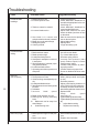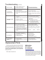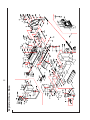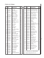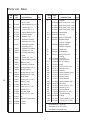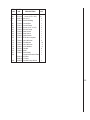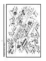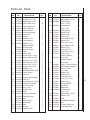
1
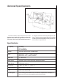
Operating Instructions & Parts Manual
10-Inch x 16-Inch Horizontal
Cut-Off Band Saw
Models 7020/7040
Part No. 9078341
Revision C4 07/03
WMH TOOL GROUP
2420 Vantage Drive
Elgin, IL 601237
TEL: 1-888-594-5866
FAX: 1-800-626-9676
www.wmhtoolgroup.com
Table of Contents
General Specifications ....................................................................................................................................... 5
Specifications .................................................................................................................................................... 5
General Specifications ....................................................................................................................................... 5
Machinery General Safety Warnings ................................................................................................................. 6
Operating Precautions ....................................................................................................................................... 6
General Electrical Cautions ................................................................................................................................ 7
Safety Instructions on Sawing Systems ............................................................................................................. 7
Introduction ...................................................................................................................................................... 8
Operating Instructions .................................................................................................................................... 8
Controls ............................................................................................................................................................. 8
Setting Blade Speed ........................................................................................................................................... 8
Operating Instructions ........................................................................................................................................ 8
Raising/Lowering the Saw Head ......................................................................................................................... 9
Controlling the Cut: Hydraulic Feed Control ...................................................................................................... 9
Evaluating Cutting Efficiency ............................................................................................................................. 9
Blade Selection .................................................................................................................................................. 9
Blade Break-in Procedures .............................................................................................................................. 10
Work Setup .................................................................................................................................................... 10
Securing the Workpiece for Square Cuts ........................................................................................................ 10
Adjusting the Vise for Angle Cuts ..................................................................................................................... 10
Work Set-up .................................................................................................................................................... 10
Installation and Adjustment of Work Stop .......................................................................................................... 11
Starting the Saw ............................................................................................................................................... 11
Adjustments ................................................................................................................................................... 12
Blade Tracking Adjustment ............................................................................................................................... 12
Coolant Flow .................................................................................................................................................... 12
Coolant Mixture and Quantity ........................................................................................................................... 12
Factory or Field Procedure .............................................................................................................................. 12
Adjustments ..................................................................................................................................................... 12
Blade Guide Bearing Adjustment ...................................................................................................................... 13
Test Cutting to Verify Adjustment Accuracy ...................................................................................................... 14
Adjustment of the Limit Switch .......................................................................................................................... 14
Maintenance ................................................................................................................................................... 14
Cleaning .......................................................................................................................................................... 14
Lubrication ....................................................................................................................................................... 14
Maintenance .................................................................................................................................................... 14
Changing Blades .............................................................................................................................................. 15
Changing the Drive Belt ................................................................................................................................... 15
Replacing the Drive Motor ................................................................................................................................ 15
Adjusting the Counterbalance Spring ............................................................................................................... 15
Replacing the Drive Wheel ............................................................................................................................... 16
Adjusting the Blade Guides .............................................................................................................................. 16
Replacement of Carbide Blade Guide .............................................................................................................. 16
Replacement of Guide Bearings ....................................................................................................................... 17
Replacement of Blade Edge Bearings .............................................................................................................. 17
Replacement of the Wire Brush ....................................................................................................................... 17
Machine Setup ............................................................................................................................................... 17
Uncrating and Spotting ..................................................................................................................................... 17
Electrical .......................................................................................................................................................... 18
Wiring Diagrams .............................................................................................................................................. 18
Troubleshooting ............................................................................................................................................. 20
3
Table of Contents
Replacement Parts ........................................................................................................................................ 21
Parts List - Base .............................................................................................................................................. 23
Parts List - Head .............................................................................................................................................. 27
4
General Specifications
The Wilton Models 7020/7040 Horizontal Cut-Off
Bandsaws are ruggedly built, precision machines designed for either wet or dry applications. The 2 HP
motor along with the worm gear reduction drive train in
an oil bath, transmits smooth and positivepower to the
blade. This drive system coupled with the recirculating
coolant system keeps the blade running cool and true,
which results in longer blade life.
Specifications
Capacity
10" Round
10" x 10" Square
9" x 16" Rectangle
Speeds
100 to 350 feet per minute - variable speed
Motor
Model 7020 - 1.5 H.P., 1 phase, 110/220V
Model 7040 - 2 H.P., 3 phase, 220/440V
Blade Size
1" x .035" x 135"
Blade Guides
Adjustable 6 point contact combination bearing and carbide
Blade Wheels
14" diameter, cast iron
Dimensions
Length: 79" / Width: 31" / Height: 41"
Shipping Weight
Approximately 725 pounds
Vise
Rapid acting, 3 jaw design
Coolant System
Recirculating system standard with each machine complete with 1 GPM pump, 8
gallon reservoir, and coolant applied through the blade guides.
5
- Misuse of this machine can cause serious injury.
- For safety, machine must be set up, used and
serviced properly.
- Read, understand and follow instructions in the
Operating Instructions and Parts Manual which
was shipped with your machine.
When Setting up Machine:
- Always avoid using machine in damp or poorly
lighted work areas.
- Always be sure the machine support is securely anchored to the floor or the work bench.
When Using Machine:
- Always wear safety glasses with side shields
(See ANSI Z87.1)
- Never wear loose clothing or jewelry.
- Never overreach - you may slip and fall.
When Servicing Machine:
- Always disconnect the machine from its electrical supply while servicing.
- Always follow instructions in Operating Instructions and Parts Manual when changing accessory tools or parts.
- Never modify the machine without consulting
Wilton Corporation.
You - the Stationary Power Tool User - Hold
the Key to Safety.
Read and follow these simple rules for best results
and full benefits from your machine. Used properly,
Wilton’s machinery is among the best in design and
safety. However, any machine used improperly can
be rendered inefficient and unsafe. It is absolutely
mandatory that those who use our products be
properly trained in how to use them correctly. They
should read and understand the Operating Instructions and Parts Manual as well as all labels affixed to
the machine. Failure in following all of these warnings can cause serious injuries.
Machinery General Safety Warnings
6
1. Always wear protective eye wear when
operating machinery. Eye wear shall be impact
resistant, protective safety glasses with side shields
which comply with ANSI Z87.1 specifications. Use
of eye wear which does not comply with ANSI
Z87.1specifications could result in severe injury
from breakage of eye protection.
2. Wear proper apparel. No loose clothing or jewelry
which can get caught in moving parts. Rubber soled
footwear is recommended for best footing.
3. Do not overreach. Failure to maintain proper working position can cause you to fall into the machine
or cause your clothing to get caught pullingyou
into the machine.
4. Keep guards in place and in proper working order.
Do not operate the machine with guards removed.
5. Avoid dangerous working environments. Do not use
stationary machine tools in wet or damp locations.
Keep work areas clean and well lit.
6. Avoid accidental starts by being sure the start
switch is OFF before plugging in the machine.
7. Never leave the machine running while unattended.
Machine shall be shut off whenever it is not in operation.
8. Disconnect electrical power before servicing.
Whenever changing accessories or general maintenance is done on the machine, electrical power
to the machine must be disconnected before work
is done.
9. Maintain all machine tools with care. Follow all
maintenance instructions for lubricating and the
changing of accessories. No attempt shall be made
to modify or have makeshift repairs done to the
machine. This not only voids the warranty but also
renders the machine unsafe.
10. Machinery must be anchored to the floor.
11. Secure work. Use clamps or a vise to hold work,
when practical. It is safer than using your hands
and it frees both hands to operate the machine.
12. Never brush away chips while the machine is in
operation.
13. Keep work area clean. Cluttered areas invite accidents.
14. Remove adjusting keys and wrenches before turning machine on.
15. Use the right tool. Don’t force a tool or attachment to do a job it was not designed for.
16. Use only recommended accessories and follow
manufacturers instructions pertaining to them.
17. Keep hands in sight and clear of all moving parts
and cutting surfaces.
18. All visitors should be kept at a safe distance from
the work area. Make workshop completely safe by
using padlocks, master switches, or by removing
starter keys.
19. Know the tool you are using — its application,
limitations, and potential hazards.
General Electrical Cautions
This saw should be grounded in accordance with
the National Electrical Code and local codes and
ordinances. This work should be done by a qualified
electrician. The saw should be grounded to protect
the user from electrical shock.
Conductor Length
0 - 50 Feet
50 - 100 Feet
Over 100 Feet
Wire Sizes
Caution: For circuits which are far away from the
electrical service box, the wire size must be increased
in order to deliver ample voltage to the motor. To minimize power losses and to prevent motor overheating
and burnout, the use of wire sizes for branch circuits
or electrical extension cords according to the following
table is recommended.
AWG (American Wire Gauge) Number
240 Volt Lines
120 Volt Lines
No. 14
No. 14
No. 14
No. 12
No. 12
No. 8
Safety Instructions on Sawing Systems
1. Always wear leather gloves when handling saw
blade. The operator shall not wear gloves when
operating the machine.
2. All doors shall be closed, all panels replaced, and
other safety guards in place prior to the machine
being started or operated.
3. Be sure that the blade is not in contact with the
workpiece when the motor is started. The motor
shall be started and you should allow the saw to
come up to full speed before bringing the saw blade
into contact with the workpiece.
4. Keep hands away from the blade area. See Figure A.
5. Remove any cut off piece carefully while keeping
your hands free of the blade area.
6. Saw must be stopped and electrical supply must
be cut off before any blade replacement or adjustment of blade support mechanism is done, or before any attempt is made to change the drive belts
or before any periodic service or maintenance is
performed on the saw.
7. Remove all loose items and unnecessary workpieces
from the area before starting machine.
8. Bring adjustable saw guides and guards as close
as possible to the workpiece.
A
B
9. Always wear protective eye wear when operating,
servicing, or adjusting machinery. Eyewear shall
be impact resistant, protective safety glasses with
side shields complying with ANSI Z87.1 specifications. Use of eye wear which does not comply
with ANSI Z87.1 specifications could result in severe injury from breakage of eye protection. See
Figure B.
10. Nonslip footwear and safety shoes are recommended. See Figure C.
11. Wear ear protectors (plugs or muffs) during e x tended periods of operation. See Figure D.
12. The workpiece, or part being sawed, must be
securely clamped before the saw blade enters
the workpiece.
13. Remove cut off pieces carefully, keeping hands
away from saw blade.
14. Saw must be stopped and electrical supply disconnected before reaching into cutting area.
15. Avoid contact with coolant, especially guarding
your eyes.
C
D
7
Introduction
This manual includes the operating and maintenance
instructions for the Wilton 10-inch by 16-inch Cut Off
Band Saw, Models 7020/7040. This manual also includes parts listings and illustrations of replaceable parts.
Operating Instructions
Controls
The operating controls for the saw are provided in a
control panel on the left side of the machine. The control panel is mounted on a pivoting tube. The pivoting
tube allows the operator to position the control panel in
a convenient location.
Power-on
Light
Motor
Pushbutton
Emergency
Reset
Button
Saw Head
Pushbutton
Figure 1: Control panel
8
1. A power-on light is provided on the left side of the
control panel. The power-on light indicates when
power is connected to the machine.
2. A n emergency stop button is provided on the
control panel. The emergency stop button provides a means to rapidly cut off electrical
power.
3. The saw motor pushbutton switch starts the saw
motor and the E-stop button stops the saw motor.
4. A green pushbutton switch is provided to the right
of the emergency stop pushbutton. The pushbutton
opens an electro-magnetic valve in the hydraulic
cylinder circuit. Opening the valves allows the saw
head to move downward and put the saw blade in
contact with the workpiece.
5. A red release button on the electro-magnetic
valve provides a means to lower the saw head
when power to the machine has been disconnected (see figure 4).
6. The rate at which the saw head moves downward
is controlled by a hydraulic feed rate control
located on the top, rear of the saw head (see
figure 3).
7. A coolant pump switch is provided on the electrical equipment box on the back of the machine
Setting Blade Speed
1. The blade speed is controlled by an adjustment
mechanism on the right end of the saw. Speed
increases when the adjustment knob is turned
counterclockwise. Speed decreases when the
knob is turned clockwise.
2. A placard on the drive belt guard provides recom
mended speeds for various materials.
3. A speed indicator is provided on the barrel of the
adjustment mechanism. The indicator provides
speed indications in feet per minute and meters
per minute. (The meters per minute values are
shown in parenthesis on the indicator.)
4. The feed rates on the placard are expressed in
meters per minute. The feed rate graduations
available on the indicator may not match the
recommended feed rate. An approximate speed
may therefore be required. For example, to set a
speed rate of 25 meters per minute, the indicator
would be set about midway between 21 metersper-minute and the 30 meters-per-minute graduations.
WARNING: TO CHANGE SPEED, THE SAW
MOTOR MUST BE OPERATING.
5. Turn the speed adjustment knob to the desired
rate setting as determined by the material being
cut.
Coolant
Pump
Switch
Figure 2: Coolant pump switch
Raising/Lowering the Saw
Head
1. Lift the saw head using the handle on the far left
side of the saw head.
2. To lower the saw head, press the green pushbutton
on the right side of the control panel.
3. To adjust the feed rate, adjust the feed rate control
valve knob on the top of the saw head (see figure
3).
4. To lower the saw head with power off, pull and turn
the red knob (manual override) on the electro-magnetic valve (see figure 4).
Controlling the Cut:
Hydraulic Feed Control
Blade Tensioning
Hand Wheel
Blade Guide Saw Head
Supports
Feed Rate
Control
Saw
Head
Saw Head
Lift Handle
Vise Clamping
Hand Wheel
Speed
Control
Blade
Drive Motor
Figure 3: Controls
ElectroMagnetic
Valve
Figure 4: Lowering head with power off
The weight of the saw arm provides all the force
needed to move the saw blade through the workpiece.
In fact, if the full weight of the arm is allowed to make
the cut, rapid blade wear and poor cutting accuracy
will result. A hydraulic feed control is provided that
gives the operator a means to control the speed and
efficiency of cutting.
The hydraulic cylinder is attached between the saw
base and the saw head. The hydraulic cylinder resists
movement of the saw head in the downward direction.
However, the hydraulic cylinder offers no resistance
when the saw head is raised upward.
The amount of downward force can be controlled by
using the feed rate control valve. When the valve is
opened slightly, the saw head will move downward. The
further the valve is opened, the faster the saw head will
move downward.
The feed control is adjusted by the operator until the
saw is operating efficiently. This is usually determined
by observing the chip formation. (See Evaluating Blade
Efficiency for more information on cutting efficiency.)
Control Box
Red
Release
Button
Belt
Cover
Evaluating Cutting Efficiency
Is the blade cutting efficiently? The best way to
determine this is to observe the chips formed by the
cutting blade.
If the chip formation is powdery, then the feed rate
is much too light, or the blade is dull.
If the chips formed are curled, but colored — that
is, either blue or straw-colored from heat generated
during the cut — then the feed rate is too high.
If the chips are slightly curled and are not colored
by heat — the blade is sufficiently sharp and is cutting
at its most efficient rate.
Blade Selection
The cut-off saw is provided with a saw blade that is
adequate for a variety of cut-off jobs on a variety of
common materials. A 4/6 vari tooth bi-metal blade
(5674011) and a 6/10 vari tooth bi-metal blade
(5674021) are available from Wilton.
See Setting Blade Speed for the speeds recommended for various materials. These selections, while
appropriate for many shop cutting needs, do not encompass the wide variety of blades of special configuration (tooth pitch and set) and special alloys for cutting unusual or exotic materials.
A coarse blade could be used for a solid steel bar
but a finer tooth blade would be used on a thin-wall
tube. In general, the blade choice is determined by
the thickness of the material; the thinner the material,
the finer the tooth pitch.
9
A minimum of three teeth should be on the work
piece at all times for proper cutting. The blade and
workpiece can be damaged if the teeth are so far apart
that they straddle the workpiece.
For very high production on cutting of special materials, or to cut hard-to-cut materials such as stainless
steel, tool steel, or titanium, you can ask your industrial
distributor for more specific blade recommendations.
Also, the supplier who provides the workpiece material
should be prepared to provide you with very specific
instructions regarding the best blade (and coolant or
cutting fluid, if needed) for the material and shape supplied.
Blade Break-in Procedures
New blades are very sharp and, therefore, have a
tooth geometry which is easily damaged if a careful
break-in procedure is not followed. Consult the blade
manufacturer’s literature for break-in of specific blades
on specific materials. However, the following procedure will be adequate for break-in of Wilton-supplied
blades on lower alloy ferrous materials.
1. Clamp a round section workpiece in the vise. The
workpiece should be 2 inches or larger in diameter.
2. Set the saw on low speed. Start the cut with a very
light feed rate.
3. When the saw has completed 1/3 of the cut, increase the feed rate slightly and allow the saw to
complete the cut.
4. Keep the same hydraulic cylinder setting and begin
a second cut on the same or similar workpiece.
5. When the blade has completed about 1/3 of the cut,
increase the feed rate. Watch the chip formation
until cutting is at its most efficient rate and allow the
saw to complete the cut (see Evaluating Blade Efficiency). The blade is now considered ready for
regular service.
10
Work Setup
Securing the Workpiece for
Square Cuts
1. Raise the saw head (refer to Figure 5).
2. Slide the left vise jaw far enough to the left to allow
the workpiece to be placed in the vise.
3. Place the workpiece on the work table. If the
workpiece is long, provide support at the other end.
It may also be necessary to provide additional downward clamping to hold the workpiece securely on
the work table.
4. Turn clamping hand wheel clockwise to clamp the
workpiece in position against the fixed (right) vise
jaw.
5. After completing the cut, turn the clamping hand
wheel counterclockwise and slide the left jaw away
from the workpiece.
Clamping
Hand
Wheel
Left Vise Jaw
Saw Head
Work Table
Figure 5: Securing workpiece
Adjusting the Vise for Angle
Cuts
1. Referring to Figure 5, loosen the angle locking screw
and the pivot screw on the left vise jaw.
2. Turn the locking handle on the round, angle-setting
block counterclockwise to unlock the block. Slide
the block until the pointer on the block is aligned
with desired angle (see figure 7). Tighten the locking handle to set the angle.
3. Set the workpiece in the vise. Put the front end of
the workpiece against the corner of the right vise
jaw. Put the rear end of the workpiece against the
angle-setting block.
4. Turn clamping hand wheel clockwise until the left
vise jaw is parallel with the workpiece. Tighten the
pivot screw and angle locking screw on the left vise
jaw. Clamp the workpiece in position.
5. After completing the cut, turn the clamping hand
wheel counterclockwise and slide the left jaw away
from the workpiece.
Angle
Setting
Block
place it against the work piece.
Set Workpiece
Against Corner
of Right
Vise Jaw
Starting the Saw
Left
Vise
Jaw
Pivot
Screw
Angle
Locking
Screw
WARNING: NEVER OPERATE THE SAW WITHOUT
BLADE COVERS IN PLACE AND SECURED.
CAUTION: MAKE SURE THE BLADE IS NOT IN CONTACT WITH THE WORKPIECE WHEN THE MOTOR
IS STARTED. DO NOT DROP THE SAW HEAD ON
THE WORKPIECE OR FORCE THE SAW BLADE
THROUGH THE WORKPIECE.
Figure 6: Adjusting vise
Angle Block
Locking Handle
Angle
Pointer
Figure 7: Angle setting block
Installation and Adjustment of
Work Stop
Figure 5: Securing workpiecThe work stop is used
to set up the saw for making multiple cuts of the same
length (see figure 8). Install and adjust the work stop
as follows:
Stop Post
1. Raise the saw head. With the saw motor off, pull
the red release button on the electro-magnetic valve
and check the rate at which the saw head lowers.
2. Raise the saw head. Push in red release button.
3. Clamp the workpiece in the vise. (See figure 9 for
examples of workpieces in the vise.)
4. Be sure the blade is not in contact with the workpiece
when the motor is started.
5. Start the motor and allow the saw to come up to
speed.
6. Slowly set the saw down onto the workpiece. Adjust
cutting speed with feed rate control valve.
7. DO NOT DROP THE SAW HEAD OR FORCE THE
CUT. Let the weight of the saw head provide the
cutting force.
8. The saw will automatically shut off at the end of the
cut.
Locking Lever
Rounds
"Wing" Screw
Stop L-Bracket
Knob
Flats/strips
Stop Rod
Knock off
sharp f f edge
here with
f
file
Figure 8: Work stop
1. Insert the end of the stop rod in the hole in the front
right side of the work table.
2. Tighten the “wing” screw to secure the rod in place.
3. Install the stop post in the channel on the back of
the stop L-bracket. Install the locking lever in the
threaded hole in the stop post. Snug-up the locking lever.
4. Install the locking knob in the hole in the side of the
stop L-bracket.
5. Slide the assembled stop L-bracket onto the stop
rod. Position the stop post against the work piece
and tighten the knob in the stop L-bracket. The
stop post can be moved left or right as required to
Channels
Squares/rectangles
Hexagonals
I-Beams
Angles
Knock off
sharp f edge
here with
file
f
Tees
Figure 9: Placing workpieces in the vise
11
Coolant Flow
CAUTION: THE COOLANT PUMP MUST BE SUBMERGED BEFORE OPERATING TO PREVENT DAMAGE TO THE PUMP.
1. The blade guides are fitted with coolant fittings.
Coolant is provided to the fittings through interconnecting tubing. The coolant is dispensed directly
onto the saw blade.
2. Adjust the coolant flow valves on the top, rear of the
saw head as required to provide the desired flow.
The flow should be no more than the blade can
draw into the workpiece by blade movement.
3. The coolant flow can be stopped in two ways:
1) By using the coolant pump switch on the
electrical equipment box, or
2) By closing the coolant flow valves on the top,
rear of the saw head.
Coolant Mixture and Quantity
The general purpose coolant is a mixture of water
soluble oil and water. Mix one part of soluble oil (TRIM
SOL) to ten parts of water (one quart oil, ten quarts of
water). Eleven quarts of coolant are required for the
coolant pump to operate properly.
There are numerous coolants on the market that are
formulated for special applications. Consult your local
distributor for details in the event you have a long range
production task, or are required to cut some of the
more exotic materials.
Adjustments
12
The efficient operation of the cut-off saw is dependent upon the condition of the saw blade. If the performance of the saw begins to deteriorate, the first item
that you should check is the blade.
If a new blade does not restore the machine’s cutting accuracy and quality, refer to the Troubleshooting
section (or the blade manufacturer’s guide) for conditions to consider and adjustments that can be made to
increase the life of the blade.
To change the blade, refer to Changing Blades in
the Maintenance section. To adjust the blade tracking,
refer to the following procedures.
Blade Tracking Adjustment
Blade tracking has been tested at the factory. Adjustment is rarely required when the blade is used properly or if the blade is correctly welded. (See figure 10
for location of blade tracking adjustment screws.)
Blade Tracking
Hex Adjustment
Screws
Single
Adjustment
Screw
Center
Locking
Screws
Figure 10: Blade tracking and tensioning
Factory or Field Procedure
1. Raise the saw head enough to allow the saw motor
to operate.
2. Loosen four knobs securing the blade cover. Lift
the cover and swing it backward.
3. Remove the blade guard mounted on the left blade
guide support.
4. Remove both blade guide bearing brackets.
NOTE: Maintain proper tension at all times using the
blade tensioning mechanism.
5. Loosen the center locking screws in all three hex
adjustment screws on the blade tensioning mechanism (see figure 10).
CAUTION: WHILE PERFORMING THE FOLLOWING,
KEEP THE BLADE FROM RUBBING EXCESSIVELY
ON THE SHOULDER OF THE WHEEL. EXCESSIVE
RUBBING WILL DAMAGE THE WHEEL AND/OR THE
BLADE.
6. Start the saw. Slowly turn the single hex adjustment
screw at the rear of the tracking mechanism to tilt
the idler wheel. Do not turn either of the other two
adjustment screws. Turn the adjustment screw until
the blade is touching the shoulder of the idler wheel.
NOTE: Turning the screw inward causes the blade to
move toward the shoulder of the wheel. Turning the
screw outward causes the blade to move away from
the shoulder.
7. Turn the single hex adjustment screw so the blade
starts to move away from the shoulder of the wheel
— then turn the single hex adjustment screw in the
other direction so the blade stops, then moves slowly
toward the shoulder.
WARNING: KEEP FINGERS CLEAR OF THE BLADE
AND WHEEL TO AVOID INJURY.
8. Turn the single hex adjustment screw to stop the
motion of the blade on the wheel as it gets closer to
the wheel shoulder. Put a 6-inch length of paper
between the blade and the wheel as shown in figure
11. The paper should not be cut as it passes between the wheel shoulder and the blade.
9. Turn the single hex adjustment screw a small amount.
Repeat the insertion of the paper between the wheel
shoulder and the blade until the paper is cut in two
pieces.
NOTE: You may have to repeat the check with the
paper several times before the blade and the shoulder
cuts the paper into two pieces. Do not hurry the adjustment. Patience and accuracy here will pay off with
better, more accurate, quieter cutting and much longer
machine and blade life.
10. When the paper is cut, turn the hex adjustment
screw slightly in the counterclockwise direction. This
assures that the blade is not touching the shoulder
of the wheel.
11. Shut off the saw.
12. Hold the hex adjustment screws with a wrench and
tighten the center locking screws. Make sure the
hex adjustment screws do not move while tightening
the center screws.
13. Install the two blade guide bearing brackets. Position the guides so the bearings just touch the blade.
14. Install the left blade guard.
15. Close the saw head cover. Tighten all four knobs.
Motor "ON"
Upper Wheel
Rotating
should rarely require adjustment. When adjustment is
required, adjust immediately. Failure to maintain proper
blade adjustment may cause serious blade damage or
inaccurate cuts.
It is always better to try a new blade when cutting
performance is poor. If performance remains poor after changing the blade, make the necessary adjustments.
If a new blade does not correct the problem, check
the blade guides for proper spacing. For most efficient operation and maximum accuracy, provide 0.001
inch clearance between the blade and the guide bearings. The bearings will still turn freely with this clearance. If the clearance is incorrect, the blade may track
off the drive wheel.
CAUTION: CHECK THE BLADE TO MAKE SURE THE
WELDED SECTION IS THE SAME THICKNESS AS
THE REST OF THE BLADE. IF THE BLADE IS
THICKER AT THE WELD, THE GUIDE BEARINGS MAY
BE DAMAGED.
If required, adjust the guide bearings as follows:
1. The inner guide bearing is mounted on a concentric bushing and can not be adjusted.
2. The outer guide bearing (closest to the operator) is
mounted on an eccentric bushing and can be adjusted.
3. Hold the bushing with a 3/4-inch wrench and loosen
Guide Bracket
Eccentric
Bushing
Locking
Screw
Put Strip
Between
Wheel
and
Blade
Blade
Outer Roller
(Blade Guide Roller)
Figure 12: Adjustment of guide bearings
INCORRECT
Outer
Roller
CORRECT
Inner
Roller
Figure 11: Checking blade-to-wheel clearance
using paper strips
Blade Guide Bearing
Adjustment
Proper adjustment of the blade guide bearings is
critical to efficient operation of the cut-off saw. The
blade guide bearings are adjusted at the Factory. They
Blade
Locking
Screw
Figure 13: Blade -to-bearing orientation
13
the center locking screw with an Allen wrench (see
figure 12).
4. Position the bearing by turning the bushing. Set
the clearance at approximately 0.001 inch. (The
blade should be in a vertical position between the
bearings. (See figure 13.)
5. Tighten the center locking screw with an Allen wrench
while holding the eccentric bushing in position with
the 3/4-inch wrench.
6. Use the same procedure to adjust the other guide
bearing.
7. When the adjustment is correct, the guide bearings should rotate freely with slight pressure of the
finger (with the blade stopped).
8.Adjust blade-edge bearings so they just touch
the back edge of the blade (see figure 19).
Test Cutting to Verify
Adjustment Accuracy
Test cuts can be used to determine whether or not
you have adjusted the blade accurately. Use 2-inch
round bar stock to perform these test cuts, as follows:
1. With the bar stock securely clamped in the vise,
make a cut through the bar stock. (See figure 14.)
2. Mark the top of the bar stock.
3. Move the bar stock about 1/4-inch past the blade so
you can begin a second cut.
4. Rotate the bar stock 180 degrees so the mark you
made is now at the bottom of the cut.
5. Make a cut through the bar stock.
6. Use a micrometer to measure the thickness varia1. Clamp in vise and mark top
of barstock here
2. Cut off a slice of
the bar stock
14
3. Rotate stock in vise
so mark is at bottom
4. Cut off a new
slice from the
stock
5. Measure
here...
New slice
6. ...measure
here
7. Differences between
measurements at edges
of disc should be less
than .003 inches per
inch per side of stock
diameter
Figure 14: Cutting a test disc
tion of the disk you have cut from the bar stock. Measure at the top and bottom of the disk.
The saw blade can be considered correctly adjusted
when the variation measure is no more than 0.012 inch
across the face of the disk.
If you do not have a piece of 2-inch bar stock available for a test cut, use a larger diameter test piece
rather than a smaller one. The maximum thickness
variation on any test piece should be no more than
0.003 inch, per side, per inch of stock diameter.
Adjustment of the Limit
Switch
1. The limit switch is provided to shut off the saw motor
when the workpiece is cut through.
2. To set the limit switch, loosen the jam nut on the limit
switch stop (figure15).
3. Adjust the stop as required and retighten jam nut.
Jam Nut
Adjustment
Screw
Switch
Roller
Limit
Switch
Figure 15: Limit switch adjustment
Maintenance
Cleaning
1. Clean off any preservative on machine surfaces.
2. After cleaning, coat the machined surfaces of the
cut-off saw with a medium consistency machine
oil. Repeat the oil coating process at least every
six months.
3. Clean up accumulated saw cuttings after use. Make
sure the lead screw is kept free of saw cuttings and
other material that would cause damage.
4. Clean the chip sludge from the coolant tank. The
frequency should be determined by how often the
saw is used.
Lubrication
Lubricate the following components at the specified
frequencies and using the lubricants as defined:
1. Ball bearings: the bearings are lubricated and
sealed—periodic lubrication is not required.
2. Blade guide bearing: the bearings are lubricated
and sealed—lubrication is not required. Inspect
periodically.
3. Idler wheel bushing: the bearings are lubricated
and sealed—lubrication is not required. Inspect
periodically.
4. Lead screw bearing housing: lubricate with light oil
monthly (see exploded figure, page 20).
5. Lead screw: lubricate with light oil monthly (see
exploded figure, page 20).
6. Hydraulic cylinder pivot: lubricate with light oil every
6 months (see exploded figure, page 20).
7. Blade tension screw: lubricate with grease every 6
months (see exploded figure, page 24).
8. Blade brush bearing: lubricate with light oil monthly
(see exploded figure, page 24).
9. Gear box: check oil once a year.
10. Change coolant on a frequency appropriate to the
type of coolant being used. Oil based coolants can
sour. Refer to the coolant supplier’s instructions
for change frequency.
11. Coolant tank: clean every 6 months or as required.
Changing Blades
WARNING: SHUT OFF ALL ELECTRICAL POWER
TO THE MACHINE.
1. Loosen four knobs securing the blade cover. Lift
the cover and swing it backward.
2. Remove the blade guard mounted to the left blade
guide support.
WARNING: ALWAYS WEAR LEATHER GLOVES
WHEN HANDLING SAW BLADE TO AVOID INJURY
FROM THE SAW TEETH.
3. Turn the blade tensioning hand wheel clockwise to
relieve tension on the blade. Loosen the blade
enough to remove the blade from the idler and drive
wheels. Remove the blade from between the blade
guides.
4. Install the new blade between the blade guide bearings and the carbide blade guides. Install the blade
over the drive and idler wheels.
5. Turn the blade tensioning hand wheel counterclockwise to tighten the blade. Tighten the blade until the
blade tension indicator reads 2000 pounds.
6. Operate the saw at low speed and observe the tracking of the blade. If tracking needs to be adjusted,
refer to Blade Tracking Adjustment.
7. Adjust the bearings on the upper edge of the blade
until they just contact the blade (see figure 19).
8. Check the guide bearings and the carbide guides
to make sure they are just contacting the sides of
the blade.
9. Install the left blade guard making sure there is
ample clearance with the blade.
10. Make a test cut to make sure the blade tracks properly during operation. Adjust tracking as required
(see Blade Tracking Adjustment).
Changing the Drive Belt
1. Disconnect the electrical power source from the
cut-off saw to prevent any possibility of accidental
motor start-up.
2. Set the arm at the full horizontal position.
3. Remove the knob on the drive belt cover. Remove
the drive belt cover to expose the V-belt and pulleys.
4. Remove two screws, nuts, and washers from back
of saw head support. Push on the motor support
bracket to pivot the motor upward to loosen the tension on the belt.
5. Remove the worn belt.
6. Put the replacement belt in the pulleys. Allow the
motor to pivot downward.
7. Install the two screws, nuts, and washers in back of
saw head support and through the motor support
bracket.
8. Install the drive belt cover. Install and tighten the
knob on the drive belt cover.
Replacing the Drive Motor
1. Disconnect the motor from all electrical power. Unplug the motor if it is plugged into a socket. Shut
off the power to the branch and remove the connection to the junction box if the motor is hard wired
to the branch.
2. Remove the drive belt from the drive motor pulley
(see Changing the Drive Belt).
3. Remove motor pulley.
4. Open the motor junction box and disconnect the
power cord wires from their terminals.
5. Remove the nuts, washers and bolts that secure the
motor to the mounting plate.
6. Installation of a new motor is a reversal of the above
steps.
Adjusting the
Counterbalance Spring
The counterbalance spring is located at the right,
rear of the saw head. The counterbalance spring is
15
Pivot
Adjustment Nuts
5.
6.
7.
8.
Threaded
Rod
Counterbalance
Spring
Figure 16: Counterbalance spring adjustment
used to adjust the amount of down force the saw head
puts on the workpiece when the feed rate control valve
is fully open.
1. Raise the saw arm to its full upright position and
lock it in position.
2. To adjust the tension on the spring, loosen the two
nuts on the threaded rod of the spring pivot post.
Adjust the tension as required.
3. Tighten the two nuts against the pivot post.
4. The saw can now be returned to service.
damaged.
Inspect bearings for damage and smooth operation, Replace if faulty.
Install the bearing in the idler wheel. Install the idler
wheel on the idler shaft.
Install the screw, spring washer and washer in the
idler shaft.
Install the blade (see Changing blades).
Adjusting the Blade Guides
The cut-off saw has adjustable blade guide supports
(see figure 17). The blade guide supports allow you to
set the blade guides for varying widths of workpieces.
To make accurate cuts and prolong blade life, the
blade guide supports should be set to just clear the
workpiece to be cut.
Blade Guide
Supports
Replacing the Drive Wheel
16
1. Remove the blade (see Changing Blades).
2. Remove the screw, spring washer, and washer from
the speed reducer shaft.
3. Pull the wheel from the speed reducer shaft. Remove the drive key from the speed reducer shaft.
4. Inspection: Examine drive edge and shoulder of
the wheel for damage. Replace the wheel if damaged.
5. Install the key in the keyway in the speed reducer
shaft. Align the keyway in the wheel with the key in
the speed reducer shaft. Reinstall the wheel on the
speed reducer shaft.
6. Install the screw, spring washer and washer in the
end of the speed reducer shaft.
7. Install the blade (see Changing Blades).
Replacing Idler Wheel or
Idler Bearing
1. Remove the saw blade (see Changing Blades).
2. Remove the screw, spring washer, and washer from
the idler shaft.
3. Remove the idler wheel. Remove the bearing from
the idler wheel.
4. Inspection: Examine the drive edge and shoulder
of the idler wheel for damage. Replace the wheel if
Figure 17: Blade guide supports
1. Loosen the knob on the blade guide support and
slide the guide left or right as required. Repeat for
the other blade guide.
2. Set the blade guide supports as required to accommodate the width/diameter of the workpiece. The
blade guides should be positioned so the guides do
not contact the workpiece as the saw head moves
downward through the workpiece.
Replacement of Carbide
Blade Guide
Concentric Bushing
Cap Screw
(Typical)
Blade Guide Bearings
Carbide
Guides (2)
Cap Screw
(Typical)
Eccentric
Bushing
Figure 18: Carbide blade guides and guide bearings
Refer to Figure 18.1.
1. Remove the cap screw and remove the carbide
guide. Discard the carbide guide.
2. Install the replacement carbide guide on the guide
bearing support. Install the cap screw. Set the
guide so it just contacts the side of the saw blade.
3. Using a machinist's square, check squareness of
the blade to the table.
Replacement of Guide
Bearings
Replacement of the Wire
Brush
1. Loosen four knobs securing the blade cover. Lift
the cover and swing it backward.
2. Remove the attaching screw, spring washer and
washer. Remove and discard the brush (see figure
20).
3. Install replacement brush and secure with screw,
spring washer and washer.
Referring to Firgure 18, remove the cap screw from
the bearing being replaced. Separate the bushing and
cap screw from the bearing. Discard the bearing.
NOTE: There is a light press fit between the bearing
and the bushing.
2. Install bushing in replacement bearing. Install cap
screw through bushing and into guide support.
3. If the bearing being replaced is on an eccentric
bushing, install the bearing on the operator side of
the blade.
4. Turn the eccentric bushing in the guide support
until the bearing contacts the blade.
Wire Brush
Screw and Washers
Figure 20: Wire brush
Replacement of Blade Edge
Bearings
Machine Setup
1. Remove the capscrew from the blade edge bearing
being replaced and discard the bearing. Be careful not to lose the spring washer that separates the
bearing from the floating block (see figure 19).
2. Insert the capscrew into the new bearing. Replace
the spring washer onto the capscrew and re-install
into the floating block.
3. If re-adjustment is necessary, loosen the pivot
capscrew and move the floating block so that the
Uncrating and Spotting
Adjustment
Cap Screw
Guide Support
Floating Block
Cap Screw
Blade Edge
Bearing
Figure 19: Blade edge bearing replacement
The saw delivered to you has been adjusted at the
factory. A number of test pieces have been cut using
the saw to verify the accuracy of cutting. Therefore,
the only setup operations required before releasing
the saw for service are spotting the saw and establishing the electrical connections to the motor.
Spot the saw where it makes the most sense for the
operations you will probably be doing. If you are going to be doing cut-off work on very long pieces of
stock, allow plenty of room for the stock, and the infeed
and outfeed supports. Remove the saw from the shipping skid and discard any hold-down devices that were
used to secure the saw to the skid.
17
4. Close the blade cover and secure with four knobs.
Electrical
Observe the following when connecting to the power
source. (The cut-off saw wiring diagrams are provided in Figures 21 and 22.)
WARNING: WILTON RECOMMENDS THAT ANY WIRING INVOLVING HARD WIRING OF THE SAW TO A
BRANCH, OR ANY CHANGE OF VOLTAGE SUPPLIED
TO THE MOTOR BE PERFORMED BY A LICENSED
ELECTRICIAN.
1. Make sure the saw is disconnected from the power
2.
3.
4.
5.
source, or that the fuses have been removed or
breakers tripped in the circuit in which the saw will
be connected. Make sure you put a warning placard on the fuse or circuit breaker to prevent accidental electrical shock.
If you are installing the motor power cord into a
receptacle, make sure to use the appropriate plug.
If you are using hard-wired connections to a junction box, connect the wires in the box, and close
the box.
Install the fuses or reset the breaker.
The saw is now ready for service.
18
Figure 21: Model 7020 cut-off saw wiring diagram
115V - To reverse motor rotation
switch terminals 5 and 6.
220V - To reverse motor rotation
hook terminal 6 to 1.
Figure 22: Connection diagram for 1ph motor
Figure 24: Model 7040 cut-off saw wiring diagram
19
Figure 25: Connection diagram for 3ph motor
Troubleshooting
Fault
Probable cause
Excessive blade
breakage
1. Material loose in vise.
2. Incorrect speed or feed.
3.
4.
5.
6.
7.
8.
Premature blade
dulling
Bad cuts
(out-of-square)
20
1. Clamp work securely.
2. Check Machinist’s Handbook for
speed/feed appropriate for the material being cut.
Teeth too coarse for material.
3. Check Machinist’s Handbook for
recommended blade type.
Incorrect blade tension.
4. Adjust blade tension to the point
where the blade just does not slip
on the wheel.
Saw blade is in contact with 5. Start the motor before placing the
workpiece before the saw is started.
saw on the workpiece.
Blade rubs on the wheel flange.
6. Adjust blade tracking.
Misaligned guides.
7. Adjust guides.
Cracking at weld.
8. Longer annealing cycle.
1.
2.
3.
4.
Blade teeth too coarse.
Blade speed too high.
Inadequate feed pressure.
Hard spots in workpiece or scale on/
in workpiece.
5. Work hardening of material (especially stainless steel).
6. Insufficient blade tension.
7. Operating saw without pressure on
workpiece.
1. Workpiece not square with blade.
2. Feed pressure too fast.
3. Guide bearings not adjusted properly.
4. Inadequate blade tension.
5. Span between the two blade guides
too wide.
6. Dull blade.
7. Incorrect
blade
speed.
8. Blade guide assembly is loose.
9. Blade guide bearing assembly
loose.
10.
Blade track too far away from
wheel flanges.
11.
Guide bearing worn.
Bad cuts (rough)
Suggested remedy
1.
2.
3.
4.
Use a finer tooth blade.
Try a lower blade speed.
Decrease spring tension.
Increase feed pressure (hard
spots). Reduce speed, increase
feed pressure (scale).
5. Increase feed pressure by reducing spring tension.
6. Increase tension to proper level.
7. Do not run blade at idle in/on material.
1. Adjust vise so it is square with the
blade. (Always clamp work tightly
in vise.)
2. Decrease pressure.
3. Adjust guide bearing clearance to
0.001 inch (0.002 inch maximum).
4. Gradually increase blade tension.
5. Move blade guide bar closer to work.
6. Replace blade.
7. Check
blade
speed
(see Figure 3).
8. Tighten blade guide assembly.
9. Tighten blade guide bearing assembly.
10.
Adjust blade tracking.
11.
Replace worn bearing.
1. Blade speed too high for feed pres- 1. Reduce blade speed and feed pressure.
sure.
2. Replace with finer blade.
2. Blade is too coarse.
Troubleshooting (Continued)
Blade is twisting
1. Blade is binding in the cut.
2. Blade tension too high.
Unusual wear on
side/back of blade
1. Blade guides worn
1. Replace blade guides.
2. Blade guide bearings not adjusted. 2. Adjust blade guide bearings.
3. Blade guide bearing bracket is
loose.
3. Tighten blade guide bearing
bracket.
Teeth missing/ripped
from blade
1. Blade tooth pitch too coarse for 1. Use blade with finer tooth pitch.
workpiece.
2. Feed too slow; feed too fast. 2. Increase feed pressure and/or
blade speed.
3. Workpiece vibrating.
3. Clamp workpiece securely.
4. Gullets loading up with chips. 4a.
Use blade with a coarse tooth
pitch—reduce feed pressure.
4b.
Brush blade to remove chips.
1. Reduce tension on blade.
2. Reduce tension on drive belt.
3. Use blade with fine tooth pitch.
Motor running too hot
1. Blade tension too high.
2. Drive belt tension too high.
3. Blade too coarse for workpiece (especially with tubular stock).
4. Blade too fine for workpiece (especially with heavier, soft material).
5. Speed reducer gears require lubrication.
1.
2.
3.
4.
1.
2.
3.
4.
No coolant flow
Excessive speed
reducer noise/
vibration
1. Decrease feed pressure.
2. Decrease tension on blade
Pump motor is burned out.
Screen/filter on pump is clogged.
Impeller is loose.
Coolant level too low.
4. Use blade with coarse tooth pitch.
5. Check
speed
reducer.
Replace pump.
Clean screen/filter.
Tighten impeller.
Add coolant to reservoir.
1. V-belt is too tight.
1. Reset V-belt tension.
2. Countering spring not tensioned 2. Increase spring tension.
properly.
Replacement Parts
This section provides exploded view illustrations that
show the replacement parts for the 10-inch x 16-inch
Cut-Off Saw. Also provided are parts listings that provide part number and description. The item numbers
shown on the illustration relate to the item number in the
facing parts listing.
Order replacement parts from:
WMH Tool Group
2420 Vantage Drive
Elgin, IL 601237
TEL: 1-888-594-5866
FAX: 1-800-626-9676
www.wmhtoolgroup.com
Identify the replacement part by the part number
shown in the parts listing. Be sure to include the
model number and serial number of your machine
when ordering replacement parts to assure that
you will receive the correct part.
21
Exploded View - Base
22
Parts List - Base
ITEM PART
NO.
NO.
1
5712251
DESCRIPTION
Foot, Left
QTY
1
ITEM
NO.
PART
NO.
DESCRIPTION
QTY
21-1
5519494
Set Screw (5/16"x1/2")
1
2
5712261
Foot, Right
1
22
5712481
Lead Screw Bracket
1
3
5712271
Coolant Reservoir
1
23
5712491
Screw (5/16" x 1/4")
2
3-1 5519485
Stopper (PT 3/8")
1
23-1
5713931
Spring Washer (5/16")
2
4
Coolant Pump
1
23-2
5713131
Washer (5/16")
2
24
5712511
Vise Lead Screw
1
5712281
115/220, 1-Phase
5712921A
220/440, 3-Phase
24-1
5519710
Key (5x5x20mm)
1
4-1 5519486
Adapter (PT 3/8")
1
24A
5514806
Collar with Pin
1
5
5712291
Pan Head Screw
2
25
5712521
Lead Screw Bracket
1
26
5712531
Acme Nut
1
5712311
5712321
5512101
5712331
(1/4" x 5/8 “)
Spring Washer (1/4")
Nut (1/4")
Filter Screen w/Screw
Hose (5/16")
2
2
1
1
27
5712541
Button
1
28
5712551
Retainer
2
29
5712561
Screw (M5 x 8)
1
8-1 5519487
Hose Clamp
6
30
5712571
Needle Bearing (CB3020) 2
9
5712341
Chip Pan
1
30-1
5519495
Bush (4mm)
1
10
5712351
Pump Bracket
1
30-2
5519496
Bush (2mm)
1
11
5712361
Work Table
1
31
5712581
Washer (1/2")
2
11-1
5519491
Label, Made in Taiwan
1
32
5712591
Pivot Shaft
1
11-2
5519492
Rivet(2mm)
Pivot Bracket
1
11-3
5519489
Hex Cap Screw (M^ x 10)
1
11-4
5519490
Washer (M6)
1
11-5
5519491
Spring Washer (M6)
1
12
5712371
Screw (1/4" x 7/8")
1
13
5712381
Hex Cap Screw (1/2" x 1") 4
13-1
5712391
Spring Washer (1/2")
4
14
5712641
Washer (1/2")
4
15
5712411
Electrical Control Box
1
15-1
5519488
Hex Cap Screw
3
6
7
7A
8
14
(5/16" x 3/4")
15-2
5513931
Spring Washer (5/16")
3
15-3 5713131
Washer (5/16")
3
15-4
5519501
Label, Pump Switch
1
16
5712421
Work Stop Bracket
1
17
5712431
Work Stop Rod
1
18
5712441
Locking Screw
1
19
5712451
Screw (1/2")
1
20
5712461
Pump Cover
1
21
5712471
Hand Wheel Assembly
1
33
5712611
34
5712621
Screw (1/2" x 3/4")
2
35
5712631
Retaining Ring (S12)
1
36
5712641
Washer (1/2")
2
37
5712651
Spring Pull Pivot
1
38
5712661
Bushing
1
39
5712671
Screw (5/8" x 1")
2
40
5712681
Regulating Seat
1
40-1
5519489
Cap Hex Screw
2
(5/16" x 5/8")
40-2
5519493
Spring Washer (5/16")
2
40-3
5713131
Washer (5/16")
2
41
5712691
Nut (3/8")
1
42
5712711
Screw (3/8"x 1")
1
43
5712721
Protractor Stop Block
1
44
5712731
Screw (M6 x 12)
4
45
5712741
Limit Switch
1
* For Saw Serial No. 704018 and Earlier
** For Saw Serial No. 704018 and Later
***Spring Changed since Dec. '96
23
Parts List - Base
ITEM
PART
NO.
NO.
46-1
5519498
DESCRIPTION
QTY
Hex Cap Screw
4
ITEM
PART
NO.
NO.
71
Overload
(5/15" x 5/8")
QTY
1
5507542 Model 7020 (115V, 1-ph)
46-2
5519493
Spring Washer (5/16") 4
46-3
TS-5713131 Washer (5/16")
4
5512660 Model 7040 (220V, 3-ph)
47
5712761
Screw (3/8" x 1")
3
5712661 Model 7040 (440V, 3-ph)
48
5712771
Spring Washer (3/8")
3
71-1
5519502 Fuse Bracket
3
49
5712781
Locking Handle
1
71-2
5519503 Fuse (1A)
3
50
5712791
Washer (1/2")
1
71A
5508409 Relay (115/220 NO)
1
51
5511502*
Hydraulic Cylinder
1
72
5713041 Magnetic Switch
1
5713031 Model 7020 (220V, 1-ph)
Assembly (2-1/2 In.)
5712811**
(115/220 1-Phase)
1
51-1 5519497
52
5712821
Hydraulic Cylinder
Assembly (3-In.)
Cylinder Pin, Bottom
Cylinder Pin, Top
53
Hydraulic Mounting
1
5712831
1
1
Plate
54
5712841
Screw (3/8" x 2)
3
55
5712851
Spring Washer (3/8")
3
56
5712861
Washer (3/8")
3
57
5712871
Protractor Vise Block
1
58
5712881
Spring Washer (1/2")
2
59
5712891
Spring Pull Rod
1
Spring (30mm) - Old
2
5519498
Spring (32mm) - New
1
61
5712921
Angle Scale
1
62
5712931
Screw (1/2" x 1-1/2")
1
63
5712941
Washer (1/2")
2
64
5712951 Vise Jaw, Left
1
65
5712961 Screw (1/2" x 1-1/2")
1
66
5712971 Washer (1/2")
1
67
5712981 Vise Jaw, Right
1
68
5712991 Screw (1/2" x 1-3/4")
2
69
5713011 Pin
2
70
5713021 Electrical Cabinet Door
1
70-1
5519499
Knob
1
70-2
5519500
Plane
1
60*** 5712911
24
DESCRIPTION
5713001 Magnetic Switch
1
(220/440 3-Phase)
73
5713051 Transformer
1
74
5713061 Terminal Strip
1
75
5713071 Spring, Protective
Casing
76 5713081 Nut (3/8")
77 5713091 Protractor Seat
77-1
5519505 Pin (5 x 32mm)
78
5713111 Knob
182
5713121 Screw (5/16"x 1/2")
183
5713131 Washer (5/16")
184
5713141 Bracket
184-1 5713931 Spring Washer (5/16")
185
5713151 Screw (3/8" x 1")
186
5713161 Washer (3/8")
187
5713171 Spring Bracket
186-1 5713481 Spring Washer (3/8")
186-2 5519507 Nut (3/8")
188
5713181 Screw (5/16" x 1/2")
189
5713191 Washer (5/16")
190
5713211 Locking Wheel
191
5713221 Screw (1/4" x 3/4")
192
5713231 Swivel Bushing
192-1 5519509 C-Ring
193
5713241 Spring Washer (1/4")
194
5713251 Screw (1/4" x 3/8")
Piston/Seal Kit 5512787
E-M valve & coil 5713371A
Not shown in exploded view.
1
3
1
2
1
2
2
1
4
2
2
1
2
2
2
2
1
2
1
1
2
2
ITEM
PART
NO.
NO.
195
196
196-1
197
198
199
200
201
202
203
204
205
215
216
217
218
219
220
221
228
229
5713261
5713271
5519510
5713281
5713291
5713311
5713321
5713331
5713341
5713351
5713361
5713371
5712301
5712401
5712501
5712601
5712701
5712801
5712901
5514613
5514616
5516855
DESCRIPTION
QTY
Control Column
1
Screw (1/4" x 3/4")
2
Nut (1/4")
2
Swivel Bushing
1
Control Box
1
Control Panel
1
Screw (3/16" x 1/4")
6
Electric Lamp
1
Start Switch
1
Stop Switch
1
Down Switch
1
E-M valve complete
1
Hex Hd Screw
2
Flat Washer
16
Hex Hd Screw
2
Lock Washer
8
Hex Nut
8
Shelf
1
Drain Shelf
1
Complete Electrical Panel 1
3-Phase
1-Phase
Coolant Pump Switch
1
25
Exploded View - Head
26
Parts List - Head
ITEM
NO.
PART
NO.
79
80
80-1
80-2
80-3
80-4
81
81-1
82
83
84
84-1
85
5713381
5713391
5518109
5519511
5519512
5519513
5713411
5519514
5713421
5713431
5713831
5712641
86
86-1
87
88
89
89-1
90
91
91-1
92
92-1
92-2
93
93-1
93-2
94
94-1
95
96
96-1
96-3
97
98
99
100
100-1
100-2
100-3
5674011
5674021
5713461
5519515
5713471
5713481
5713491
5519671
5713511
5713521
5713661
5713531
5519672
5519673
5713541
5519674
5519490
5713551
5519675
5513734
5713571
5519676
5519677
5713581
5713591
5713611
5713621
5519678
5519679
5713131
DESCRIPTION
Screw (1/4" x 3/8")
Blade Wheel Cover
Label, Wilton Logo
Label, Blade Size
Label, Warning
Label, Glasses
Wire Brush Guard
Label, Saw
Handle
Washer (1/2")
Drive Wheel10
Washer (1/2")
Blade, Bi-Metal
4/6 Vari Tooth
6/10 Vari Tooth
Hose
Hose Clamp
Screw (3/8" x 1-1/4")
Spring Washer (3/8")
Screw (1/2" x 1-1/4")
Setscrew (3/8" x 1/2")
Screw (5/16" x 1/2")
Screw (1/4" x 5/8")
Washer (1/4")
Blade Wheel Box, Right
Label, Tension
Label, ID
Support Bracket Seat
Nut (1/2")
Hex Cap Screw (1/2"x 2")
Gear Box Assembly
Key (7x7x40mm)
Key (7 mm)
Pulley Cover
Knob
Label, Speed Chart
Gear Box Pulley
Belt
Motor Pulley
Base Plate
Rod
Bracket
Washer (5/16")
QTY
1
1
10
1
1
1
1
1
2
1
1
1
1
1
4
4
4
2
2
2
4
1
1
1
1
1
1
1
1
1
1
1
1
1
1
1
1
1
1
1
ITEM
NO.
PART
NO.
100-4
100-5
5713931 Spring Washer (5/16")
5519680 Hex Cap Screw
(5/16" x 1-1/4")
5519506 Hex Cap Screw
(5/16" x 1/2")
5519681 Bushing (9mm)
5713131 Washer (5/16")
5713631 Washer (5/16")
5713661 Washer (1/4")
5713651 Spring Washer (1/4")
5713661 Washer (1/4")
5713671 Screw (1/4" x 3/8")
5628371 Spring Washer (1/2")
5713691 Washer (5/16")
5713711 Screw (3/8" x 1")
5713721 Screw (5/16" x 5/8")
5713731 Motor (1.5 HP
115/220 1-Phase)
5713732 Motor (2 HP
220/440 3-Phase)
Label, Motor
5519682 (1.5HP, 115/230 3-Phase)
5519683 (2HP, 220/440 3-Phase)
5713741 Bolt (1/2" x 3/4")
5513733 Key (7 mm)
5713761 Washer (1/2")
5713771 Washer (5/16")
5713781 Screw (M16 x 30)
5713791 Screw (1/2" x 3/4")
5713811 Washer (1/2")
9100321 Bearing (6205Z)
5713441 Idler Wheel
5713841 Blade Guard
5519506 Hex Cap screw
(5/16" x 1/2")
5713931 Spring Washer (5/16")
5713131 Washer (5/16")
5713851 Left B
5713851A Right Blade Guide Brkt.
5519684 Tube
5717138 Eccentric Shaft Assy.
5517142 Center Shaft Assy.
100-6
100-7
100-8
102
103
104
105
106
107
108
109
110
111
111-1
112
114
115
116
118
119
120
121
122
123
123-1
123-2
123-3
124
124A
124-1
125A
125B
DESCRIPTION
QTY
2
1
1
2
2
2
1
2
2
6
4
4
2
4
1
1
1
1
1
1
2
3
1
1
2
1
1
1
1
1
2
2
2
2
27
ITEM
NO.
PART
NO.
126
126-1
126-2
126-3
5713871
5713661
5713651
5519508
127
127-1
5713881
5519508
127-2
127-3
128
129
130
131
132
133
134
134-1
135
136
137
138
5713651
5713661
5713891
5713911
5632831
5713931
5713941
5713951
5713961
5518423
5713971
5713981
5713991
5714011
138-1
138-2
139
139-1
140
141
142
143
144
5519685
5519686
5714021
5713761
5714031
5714041
5714051
5714061
5714071
145
146
147
147-1
148
149
150
151
152
153
154
155
156
5714161
5713661
5714111
5519687
5714121
5713931
5714141
5713651
5714161
5628371
5714181
5714191
5714211
DESCRIPTION
Blade Guide Tung. Carb.
Washer (1/4")
Spring Washer (1/4)
Hex Socket Cap Screw
(1/4" x 1")
Elevating Block
Hex Socket Cap Screw
(1/4" x 1")
Spring Washer (1/4")
Washer (1/4")
Active Block
Screw (1/4" x 5/16")
Bearing (608ZZ)
Spring Washer (5/16")
Screw (5/16" x 1-3/4")
Spring Washer (5/16")
Guide Support
Label, Blace Orientation
Angle Scale
Screw (M5 x 0.8)
Guide Support Mount
Guide Support Bracket
(left)
Rubber Clamp
Pan Head screw (M5 x 8)
Screw (1/2" x 1")
Washer (1/2")
Knob
Washer (3/8")
Locking Block
Screw (5/16" x 1/2")
Guide Support Bracket
(Right)
Bolt (1/4" x 1/2")
Spring Washer (1/4")
Wire Brush
Shaft
Steel Brush Seat
Spring Washer (5/16")
Hose Clamp
Spring Washer (1/4")
Screw (1/4"x 1/2")
Spring Washer (1/2")
Gib
Screw (1/2" x 3/4")
Screw (M8 x 20)
QTY
2
8
4
4
2
4
4
4
2
2
4
4
4
4
2
2
1
4
1
1
4
4
4
4
2
2
2
4
1
1
1
1
1
1
2
2
4
4
4
2
1
4
ITEM
NO.
PART
NO.
156-1
158
159
159-1
160
161
161-1
5519688
5714221
5714231
5519689
5714241
5714251
5519690
161-2
162
163
163-1
163-2
164
165
166
166-1
166-2
167
172
173
174
175
176
177
178
179
180
180-1
210
210-1
210-2
210-3
5519691
5714261
5714271
5519692
5519693
5714281
5714291
5714311
5519694
5519695
5507790
5714331
5711091
5714351
5714361
5714371
5714381
5714391
5714411
5714421
5713481
5714431
5713131
5713931
5519489
211
212
213
214
216
218
219
222
222-1
223
224
5714441
5714451
5714461
5714471
5516850
5516851
5516852
5516849
5713931
5713101
5713201
5713301
DESCRIPTION
Spring Washer (MB)
Knob
Flexible Nozzle
Flow Valve
Blade Wheel Shaft
Threaded Nut
Pan Head Screw
(M6x12)
Tension Scale
Screw (5/16" x 1/2")
Slide Bracket
Nut
Set Screw
Washer
Relief Valve
Connection Head
Rubber Clamp
Pan Head screw (M5x8)
Bearing (51104NJK)
Bow Handle
Nut (1/2")
Washer
Special Spring Washer
Hand Wheel
Slide Bracket
Tension Shaft
Key (5 mm)
Screw (3/8" x 2-1/2")
Spring Washer (3/8")
Oil Pressure Seat
Washer (5/16")
Spring Washer (5/16")
Hex Cap Screw
(5/16" x 5/8")
Cover Cap
Screw (5/16" x 5/8")
Control Panel
Screw (1/4" x 3/8")
Washer
Spring Washer
Nut, Hex
Screw
Spring Washer (5/16")
Motor Pivot Bracket
Motor Pivot Bracket Shaft
Snap Ring
QTY
4
4
1
2
1
1
2
1
1
1
1
1
1
1
1
1
1
1
1
2
1
13
1
1
1
1
3
3
1
2
2
2
1
2
1
2
6
6
6
4
4
1
1
2
ITEM
NO.
PART
NO.
226
227
230
231
232
233
234
235
236
236-1
5713401
5713501
5713941
5712881
5517141
5517140
5713861
5713761
5519696
5711091
DESCRIPTION
QTY
Screw
Motor Bracket - Fixed
Screw (5/16 x 1-3/4)
Spring Washer (1/2")
Eccentric Shaft Bushing
Center Shaft Bushing
Ball Bearing (6201ZZ)
Washer (1/2")
Arm Stop
Nut (1/2")
2
1
4
4
2
2
8
4
1
1
Wilton Corporation
300 South Hicks Road
Palatine, IL 60067
TEL: 1-888-594-5866
FAX: 1-800-626-9676