1
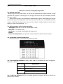
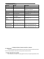
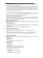
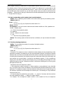
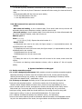
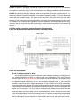
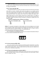
Security Alarm Controls Host User Manual Edition 3.0 Copyright Declare It professional security alarm host Preface Welcome to choose our alarm system to protect your life and property. We advise you to read this manual conscientiously before using this system and operate according to it. We are deeply convinced, this product fully reflects its convenience and adaptability whether in appearance, function, or in operating and using. Use the manual, can answer your most doubt. Meanwhile, we will offer the perfect after-sale service, and keep in touch with you at any time. 1 It professional security alarm host Catalogue 1.Summary. .................................................................................................................................................... 3 1.1Overview. .......................................................................................................................................... 3 1.2. Brief introduction of function. ..................................................................................................... 3 1.3. Fundamental fittings..................................................................................................................... 3 2 . Main technical performance .................................................................................................................. 3 3 .Remote controller and keyboard operation .......................................................................................... 4 3.1. Operate overview .......................................................................................................................... 4 3.2. Daily operation of the remote controller; .................................................................................. 4 3.3. Instruction of the keyboard panel .............................................................................................. 4 3.4. Functions of the keyboard ........................................................................................................... 5 3.4.8.Force to cut off communicating of the host ............................................................................ 6 4. Study and delete of remote controller or detector .............................................................................. 7 4.1. Explanation .................................................................................................................................... 7 4.2. Study and delete the methods .................................................................................................... 7 4.3. Study ............................................................................................................................................... 8 4.5. Reset the system........................................................................................................................... 8 5. System programmed ................................................................................................................................ 8 5.1. Enter the programming state ...................................................................................................... 9 5.2. Exit from the programming state ............................................................................................... 9 5.3. Setting of Installer code ............................................................................................................... 9 5.4. Setting of user's password......................................................................................................... 10 5.6. User’s networking serial number (user's serial number) ....................................................... 11 5.7. The first alarming telephone. .................................................................................................... 11 5.8. The second alarming telephone................................................................................................ 12 5.9. The third alarming telephone .................................................................................................... 12 5.10. Report codes of the zone. ....................................................................................................... 12 5.11 Keyboard Panic A key close or open..................................................................................... 13 5.12. The attribute amend of zone .................................................................................................. 13 5.13. System state code and the center select of the bypass code report ................................ 14 5.14. Testing the communication with the center .......................................................................... 15 5.15. Codes of arm and disarm ........................................................................................................ 16 5.16. Setting of enter/exit time, alarming sound ........................................................................... 16 5.15. Detector’s battery low in voltage checking and force arm ................................................. 17 5.16. Wire zone and horn prevent cut alarming ............................................................................ 18 6. System installation is debugged. ......................................................................................................... 18 6.1. Design execution project. .......................................................................................................... 18 6.2. The system connection and performance characteristic ....................................................... 20 7. Glossary.................................................................................................................................................... 22 8. Products assurance ................................................................................................................................ 23 9. Install data .............................................................................................................................................. 23 2 It professional security alarm host 1.Summary 1.1Overview. The system is with 8 wire + 8 wireless zones. It adopts advanced MCU design, high integrated level, good dependability, having many kinds of flexible interface. For example, resist distort alarm, super lightning proof function which make the products world widely used 1.2. Brief introduction of function. Adopts the digital communication way of the high speed, use Contact ID or Adecome4+2 communication sends the signal to the alarming center. 8 wire + 8 wireless zones. Use the host + keyboard mode, one host can connect most 6 keyboards. Able to Set 5 different arm modes: away arm, home arm, single zone arm, delay arm and remote arm Able to Set 5 different zone types: real time zone, delay zone,24-hour zone, by pass zone, perimeter zone Remote controller for armed, disarmed , etc Shortcut keys operate by keypad, easy and fast Able to set Six groups(six digits)of user's password to make sure higher security With the anti-cutting function Can set 3 group of receiving alarm number With SOS button to emergency alarm With reporting to the alarming center regularly, and auto-balance the time of sending test report out. Able to set up different programs of the system, such as sound, zone type, phone number etc Have watchdog function, prevent the system halted. Arm disarm programming with keyboard Can freely change the alarm code and other affairs code. 1.3. Basic configuration Iron case * 1pcs The transformer * 1pcs Host board * 1pcs Keyboard *1pcs Accessory : 1pcs of aerial, 8pcs of 2.2K EOL, 1pcs of guarantee card,3pcs of Jumper, one pair of Keys,1 pcs of Manual 2 . Main technical performance Power suppler: AC220V± 10%; AC working power: 15V AC; Reserve battery: DC12V; The biggest output power: 1000mA; Direct current is exported: 14V; The greatest consumption: 35W; Alarm output current: 400mA, 12V; Each zone can be connected: 15 detectors (line’s resistance less than 200 ohms) ; Environment temperature: -10-55℃; Environmental humidity: 40-70%; Weight: 2.5kg; 3 It professional security alarm host Size: 220MM *260MM *83MM 3 .Remote controller and keyboard operation 3.1. Operate overview Before you go to work or leave home, you can arm the system with the remote controller, or input password with keyboard. If anybody goes in, will trigger the sensor and system will alarm and auto dial users' mobile. When you arrive home, you can disarm the system and then get in. After disarming, the zone’s led indicator light will all long twinkle what have been touched off zones, until dispelling alarming memory. Dispelling alarming memory can press the remote controller’s disarm key two times quickly, or input: user’s password ﹡1 # 3.2. Daily operation of the remote controller; Emergency. Meet with rob or the acute disease for help. Away arm. Arm the all zones; Home arm. Arm the all zones besides the inside zones; Disarm. Delete alarming memory: can press the remote controller’s disarm key twice quickly 3.3. Instruction of the keyboard panel Use three core wire to connect the keyboard to the host. 3.3.1. The zone LED indicator:1, 2, 3, 4, 5, 6, 7, 8: It is to indicate if the zone be triggered , bypassed or alarmed. Display status Explanation on The zone is triggered off Normal status Flash slowly The zone been bypassed Once alarm in the zone 3.3.2. LED Pow indicator: Used in the display system and exchange AC220V or DC12V and supply power normally; 4 It professional security alarm host 3.3.3. LED Arm indicator : The indicator is on while arm the host, the indicator off when disarm. Display status Explanation On arm status off Disarm status 3.3.4. LED Com indicator : When the host dial the phone, the indicator will on. 3.3.5. LED Low indicator : When the Low indicator on, mean there are some wireless detector lower battery. 3.3.6 Away, Stay, Mem and BYP function key explain: MEM: Panic alarm, silence panic alarm key. Away: Away arm. Stay: Home arm. BYP: When the Low indicator on, press BYP key once, you can see which wireless zone detector lower battery, press BYP key again, able to check the next lower battery zone detector 3.3.7. Sound instruction When operating the host, the buzzer sound stands for different meanings. The sound briefs on Explanation A long Beep The system accepts the order from remote controller or keyboard A short Beep Press the key each time with a ring Three short Beep Input or remote control is invalid Short Beep second When system begin dealing time arm, the butter ring until the delay time over Per 3.4. Functions of the keyboard 3.4.1. Arm Define: The system enters the state of arm, if one zone is touched off (except the zone already bypassed), the host will dial the phone. A. Away arm Form : User' s password #, User' s password﹡5# or press keyboard’s AWAY key.( AWAY must be programming work) For example: 123456#, 123456﹡5#, If arm successfully, the system will make a long beep and LED arm indicator on. If not, the system will make 3 beeps, then will be 2 reason: one is user password error, the other is some zones on opening status, and the system can't be armed by force. If have set delay zone, the keyboard emit Di,Di,Di…. until delay time over. Then the host enter arm state. B. Home arm The all zones enter armed status besides the zones been setting to inside zone. Form : User' s password﹡3# or press keyboard’s C key.(STAY must be programming work) 5 It professional security alarm host For example: 123456﹡3# or press keyboard’s STAY key. 3.4.2. Disarm Form: User's password# or User's password﹡6# For example: 123456# or 123456﹡6# Comments: once touching off the delay zone, disarm the host in delay time will not alarm. 3.4.3. Some zones bypass and bypass recover Define: Mean when have armed the host that use bypass order to make some zones inoperative temporarily. Form: Bypass: User's password ﹡8n#, (n is zone number 1-8). Bypass recover: Repeat the operation above. For example: If Someone at home and want to arm zone 1 gate and zone 2 windows ,but zone 3 sitting room not arm, so zone 3 sitting room must be bypass .(note: if this zone has already set up for "can’t be bypass", then this zone can’t be bypass ). Operation is: user's passwords﹡83 #. If input user's passwords﹡83 # again, the zone 3 bypass is removed. 3.4.4. Delete alarm memory Comments: When some zones be touched off, after disarming, the zone indicator flashes, then input the command able to delete the alarm memory Form: user' s passwords ﹡1# Explain: Press the remote controller’s disarm key twice can realize the same function. 3.4.5. Enter the programming status Form: Installer code ﹡0# After entering the programming, power, state, arm, 3 indicator flashes. Notice: Before entering programming, the system must be in disarming status. 3.4.6. Exit programming status Exit programming status, there are 2 methods. First, stop press any key for 1 minute, system exit automatically; Second , press ﹡#s after programming. Form : ﹡# 3.4.7. Testing the communication with the alarm center If you want to know whether the host communicates good with the alarm center. When the host on disarmed status you can operate: installer code (012345)+*43#. The host auto-dialing the center telephone number and send the testing report code. If the host sent testing report code success that the host will cry long Beep, or else, the host cry short 3 seconds and continue dial the alarming center phone. 3.4.8. Force to cut off communicating of the host In the disarm status of the host, you can operate: installer code (012345)+*68# to force the host cut off the communicating. Operated success, the com led light off that mean the host exit dial the phone status. 6 It professional security alarm host 3.4.9 Keyboard operate orders: Function Explain Operation Enter programming Setting host parameter [Installer code]+*0# Exit programming Exit setting state *# AWAY,STAY key AWAY key is work Arm Away arm [password]+#or[password]+*5# Disarm Disarm [password]+#or[password]+*6# Home arm Close inside zone [password]+*3# MEM panic Silence panic MEM panic Bypass and resume Temporarily bypass some zone, n is 1-8 zone [password]+8n# Dispel memory Delete alarm memory [password]+*1# alarming Amend password AWAY arm,STAY arm Installer to amend, N is 1-6,X is [Installer code]+*0# 0N+NXXXXX# 1-9 Testing the communication Test the host whether good communication with the center [Installer code]+*43#or[Password]+*43# Force to cut off communication Close the host [Installer code]+*68#or[Password]+*68# 4. Study and delete of remote controller or detector 4.1. Explanation It has been designed the advanced detector study function, Remote controller and various kinds of wireless detectors must study and can just enter conduct use first. 4.2. Study and delete the methods Touch off detector, it transmit one group signal to the host, the signal representative of the 7 It professional security alarm host detector’s code, host confirm the code, then the detector learn successfully. There are two groups that jump the line on receiving the module wirelessly, one group is used for choosing the zone, it is J1-J4 respectively, another group uses and points out operates, including: P-2and. The host have the function that anyone zone can learn two different code controller or detector. 1. P open, 2ND open, close 1-4 jumper, detector will be learn to 1-4 zone the first situation. 2. P close, 2ND open, close 1-4 jumper, detector will be learn to 5-8 zone the first situation. 3. P open, 2ND close, close 1-4 jumper, detector will be learn to 1-4 zone the second situation. 4. P close, 2ND close, close1-4 jumper, detector will be learn to 5-8 zone the second situation. 4.3. Study 1 Choose the zone :Learn detectors to 1-4 zones, close the jumper of 1,2,3 or 4 ,and P jumper is opens; learn detectors to 5-8 zone, close P jumper, then chose 1,2,3 or 4 jumper to learn detector to the host. For example: Learn the detector to 4th zone, close jumper 4; Learn the detector to the 6th zone, need close P first , and then close jumper 2. 2 To yard: After closing the relevant Jumper, press remote controller anyone key or touch off detector make their transmit the signal, If the host accept their signal, the receive LED1 will on, show host accept signal of detector. Notice: If the detector stops transmitting the signal, the LED1 will continue light. 3 Make the Jumper 1, 2, 3, 4 ,P and 2ND on open state. 4 If need to continue learn new remote controller or detector, do the step 2-4 again. 5 Pull out all jumper . 6 Touching off the detector, the host will recognize the detector according to the zone of learning. Notice: If a remote controller or the detector has already learnt to a zone, we learns it again to another different zone, the system will delete that zone of before learning automatically. 4.4 Delete wireless memory from the host Installer code+*71-78# The host in disarm state, input the Installer code*7n#(n is 1-8, mean 1-8 zone). For example: need to delete the fourth zone wireless message, operate: 012345*74# 4.5. Reset the system When the installer forgets the password or setting confusedly, we need to resume the host system programming to default. Method: Under disarm state, make the host’s RESET jumper in close state, then input 951753﹡82# at the keyboard, after input all indicator lamp will on, with emit long beep , the indicator lamp returns to normal, the system is restored to the default. Notice: When reset the host, besides the wireless message save in the host, the installer code, password, telephone number, zone attribute….all changed to the default. Make a caution about the operation. 5. System programmed This system uses the keyboard programming 1. Disarm the system before entering into programming 2. Must input two digital programming addresses, for instance: 08. 8 It professional security alarm host 3. Each programming address have 6 number, it address must finish input full 6 number, then use # end, otherwise it is invalid to input; 4. The input on each address is end with the #, the function of the key # is equivalent to the enter key on the keyboard of the computer; To the enter of the telephone number, if key is input not enough 6 figure and input #, representing the ending of the telephone number, the figure for the future is cancelled automatically, if finish the input key in 6 figures and press #, representing finishing the input on this address. The input method of counting A-F of hexadecimals number system is: ﹡0 =A, ﹡1 =B, ﹡2 =C, ﹡3 =D, ﹡4 =E, ﹡5 =F; If input A , press ﹡ on the keyboard first , then press 0, A is at the into corresponding position, analogize while being other. Notice: ﹡0 only represent a digital number. The explanation about reporting code: If insert the data except 00 on the data position in a certain report, when the relevant event happens reporting to the centre. If input 00 at the address, the system will think this report canceled. 5.1. Enter the programming state Define: Setting various kinds of parameters of system, programming is operated and can only be finished by installer. Form : Installer code﹡0# After entering programming, three indicator lamps glimmer together in the power, state, arm on the keyboard. Notice: The system can just be to its programming under disarming. 5.2. Exit from the programming state Define: After setting the systematic parameter, exit from the programming state. Form : ﹡# After exiting from programming state, power , state , arm, 3 indicator return to normal. Notice: No any pressing on button, exit from the programming state automatically. 5.3. Setting of Installer code Define: Installer code is superfine code, can use it to programming, and can carry on all other operations. Address yard: 00 Form: ×××××× (1)(2)(3)(4)(5) (6)-- the serial number of ×. Default: 012345. Data location: (1) Data fixation is 0 For example: Need to change yard 012345 to 023456, operate: 012345 -- Input former Installer code first (default). ﹡0# --Enter the programming state. 00--Address yard. 023456 --Installer code after changing. # --Input end ﹡# --Exit from the programming state 9 It professional security alarm host 5.4. Setting of user's password Define: Users password use to operate arm, disarm, bypass, etc. There can be passwords of 6 users at most in the system, after a certain user operates; the system will send a report to the center, the report points out which user's operating system. Address yard: 01-06 Form: ×××××× (1) (2)(3)(4)(5) (6)--Express the serial number of ×. Default: The default of 01 address is 123456; there is no default on 02-06 address. For example: There are three people in one unit now, need to have three passwords, they’re 123456, 234567, 345678 respectively 012345 --Installer code. ﹡0# --Enter the programming state. 01 --Write into the address yard. 123456 --User's password of the 1st (the first number must be 1). # --User's password is input end on the 1st. 02 --Write into the address yard. 234567 --User's password of the 2nd (the first number must be 2). # --User's password is input end on the 2nd. 03 --Write into the address yard. 345678 --User's password of the 3rd (the first number must be 3). # --User's password is input end on the 3rd. ﹡# --Finish the programming state, enter the state service of the keyboard. 5.5 Communication protocol setting Define: Use to setting the communication protocol of host when it dial. Address yard: 07 Form: ×××××× (1) (2)(3)(4)(5) (6)--Express the serial number of ×. Default: 212121 Explain: (1) The first telephone communication protocol setting. 1,Adecom4+2 2,Contact ID 5,User phone(Phone or mobile) (3) The scond telephone communication protocol setting. 1,Adecom4+2 2,Contact ID 5,User phone(Phone or mobile) (5) The third telephone communication protocol setting. 1,Adecom4+2 2,Contact ID 5,User phone(Phone or mobile) (2)(4)(6) default is 1. For example: Need to set the first phone use Contact ID communication protocol to the alarming center, the second phone use Adecom4+2 communication protocol to the alarming center, the third phone use to dial the phone, the operate is: 012345──Installer code *0#──Enter programming state 07──address 211151──three phone communication protocol setting #──End *#──Exit 10 It professional security alarm host Notice: Adapt Contact ID or Adecome4+2 communication protocol must sure the host connect with the alarming center. If have set the phone with Contact ID or Adecome4+2 communicate to dial ordinarily phone, the host will endless dial the phone 6 times. If have set to dial user phone, when the host dial your phone and pick up, you can hear impulse voice, you must to press the phone keyboard 1~9 figure then to hang up, otherwise the host will endless dial the phone until press the 1~9 figure then to hang up. 5.6. User’s networking serial number (user's serial number) Define: Users' networking serial number is the serial number gave by the alarming centre. Address yard: 09. Form: ×××××× (1) (2) (3) (4) (5) (6)--Express the serial number of ×. Dfault: 000000 For example: If one user's center networks serial number definite as 1234, operation are: 012345 --Installer code. ﹡0# --Enter the programming state. 09 --Address. 001234 --Network the serial number. # --end ﹡# -- Exit from the programming state. Notice: This warning system is that the last four is effective, the top two takes the location by 0. 5.7. The first alarming telephone. Define: The 1st telephone number, it is maxium 24 digital numbers. Address yard: 10-13. Form: ×××××× (1) (2) (3) (4) (5) (6)--Express the serial number of ×. Dfault: No Comments: The system can set up 3 telephone number totally, can send respectively, at the same time or backup. The telephone of every way sets dialed 3 at most, 25 minutes of interval between each one. Each one sets dial times of the number is already set up times at most. As to sending at the same time, the telephone sent at the same time must be all put through, and send success. As to send backup , set dial the 1st telephone number , if the 1st telephone busying, then set dial the second, second busying too, it is set dialing all ways telephone, until putting through one among 3 telephone number or half times of dialing set up of every group among them all the way . Introduction about the telephone number: 1. If the telephone number exceeds 6, 6 -figure number on every address is over, input the key #, and enter input of the next address. It is the same that this follows data entry on other addresses. The telephone number on the last address is often fewer than 6, Input the key # at this moment, represent end of the telephone number input. The meaning of # key is different from the former one. 2. If need to setup the outside line, can input B (﹡1 ) , stop for 3 seconds, and then continue the input outside line. Notice ﹡1 taking up a figure location . For example: The 1st telephone needs to dial 9 to the outside line first, the telephone 11 It professional security alarm host number is 3337783. 012345. ﹡0# 10 - -Address 10 9 --Put through the outside line first ﹡1 --Stop for 3 seconds 3337 --Data of this address left # --Finish the introduction on this address 11 --Address 11 783 --Data left # finishes the input of the telephone number ﹡# --Exit from the programming state. Note: If want to delete the first group of telephone numbers, press # directly to complete after inputting the 10 address code 5.8. The second alarming telephone Define: The 1st telephone number, it is 24 digital numbers at most. Address yard: 14-17 Form: ×××××× (1) (2) (3) (4) (5) (6)--Express the serial number of ×. Dfault: No Other refer to the first alarming telephone 5.9. The third alarming telephone Define: The 1st telephone number, it is 24 digital numbers at most. Address yard: 15-18 Form: ×××××× (1) (2) (3) (4) (5) (6)--Express the serial number of ×. Dfault: No Other refer to the first alarming telephone 5.10. Report codes of the zone. Define: Used for defining the zone of alarming, alarming resume and bypass code. 26-31 address represent zone 1-8. When the 07 address use Contact ID communication protocol, the host will use the Contact ID code transmit message, if you want to change 1-8 send different message to the alarming center, you can change 26-33 address the first (1) to the next mean different represent for: 1, Fire 2,Panic 3,Theft 4,Medcine 5,Hijack Address yard: 26- 33 Form: ×××××× (1) (2) (3) (4) (5) (6)--Express the serial number of ×. Dfault: 31E100 32E200 33E300 34E400 12 It professional security alarm host 35E500 36E600 37E700 38E800 Comments: (1) (2) represent the alarming code of zone. (3)(4)Represent resume codes of the zone. (5)(6)Represent the bypass code of zone. Note: If the code is set up for 00, the corresponding report does not send to the center, that is to say cancel the report. 5.11 Keyboard Panic MEM key close or open Define: Use to Control the MEM key close or open, open mean can press the Key to send panic to the center, default is close. Address yard: 34 Form: ×××××× (1) (2) (3) (4) (5) (6)--Express the serial number of ×. Dfault: 000000 (1)(2) is 00 mean close the key, other number(01-99) mean open the key. On A open state, press the A key that the host will silence to send alarm message to the center. 5.12. The attribute amend of zone Define: To define the selection of the notice telephone of each zone; Response time of zone; if zone can the bypass; type of zone; alarming sound, etc. Address yard: 36 –43 Form: ×××××× (1) (2) (3) (4) (5) (6)--Express the serial number of ×. Dfault: 021210 Comments: (1)The choice of the alarming center telephone, the code is as follows: 0: First telephone number is the receiving alarm number, the second telephone number is backup, if the first obstructed, then dial the second phone. 1: the first telephone number; 2: the second telephone number; 3: the first, the second telephone number; 4: the third telephone number; 5: the first, the second telephone number; 6: the second, the third telephone number; 7:the first, second, the third telephone number; (2)The time each zone response, the code is as follows: 0:5 ms (millisecond); 1:160ms; 2:320ms; 3:480ms; 4:720ms; 5:880ms; 6:1040ms; 7:1200ms; (3)Zone can be bypassed. 1: Zone can be bypassed; 2: Zone can not be bypassed; (4)Type of zone 1: 24 hour zone 2: Real time zone; 13 It professional security alarm host 3: Delay time zone; 4: No use; 5: Inside real time zone; 6: Inside delay zone; (5)Select of alarming sound of horn and buzzer; 1.the horn and buzzer, sound at the same time; 2.the horn and buzzer, mute; (6) Wire detector connect type 0.Normal close zone 1.Connect EOL 2.2K 2.Wire zone close (If set to 2 mean the wire zone are not work, you didn’t to connect EOL 2.2K or lead to the Zone port) Notice: the seventh and the eighth zones can’t be set to delay zone. For example: Now define zone 3 as notice the first telephone number, detector’s relay keeping open state for 880ms, this zone this can bypass, people enter door is delay time to alarm when touching off , horn and buzzer sound loudly. The wire zone is not work. Operation is: 012345; ﹡0# 38 151312 # ﹡# 5.13. System state code and the center select of the bypass code report Define: Used for reporting various kinds of working state of the system and bypass report, and the choice send to the center. Address yard: 46 Form: ×××××× (1) (2) (3) (4) (5) (6)--Express the serial number of ×. Dfault: 00D000 Comments: (1)Select telephone that zone send bypass report to 1: the first telephone number; 2: the second telephone number; 3: the first, the second telephone number; 4: the third telephone number; 5: the first, the second telephone number; 6: the second, the third telephone number; 7:the first, second, the third telephone number; (2)Have not defined (3)Reports codes, if cancel this report for 0, there is only one to pay attention to. The system working state report code will expand one automatically while sending the center, expand one yard of meaning: 1: The storage battery is insufficient in voltage 14 It professional security alarm host 2: Exchange AC220V lose electrical power 3: No defined 4: No defined 5: The communication fails; 6: The voltage of the storage battery returns to normal; 7: AC 220V resumes supplying power; 8: No defined 9: No defined B: host is restored to the center; C: programming is finished; Notice: 3 address mean code send to the centre, if some detector’s battery low in voltage, the center will receive D3, D3 mean the storage battery is insufficient in voltage, the same to the other digital, you also can change the D to 1-9, A-F, if you changed 3 address to 1-9, A-F, the center should receive 1-9, A-F+ expand one address. (4)The system report chooses, see (1) address. For example: Want to cancel the systematic working state report, operation is: 012345 ﹡0# 46 000000 # ﹡# 5.14. Testing the communication with the center Define: The host sends self-checking report to the alarming center regularly Address yard: 47 Form: ×××××× (1) (2) (3) (4) (5) (6)--Express the serial number of ×. Dfault: 990618 Comments: (1) (2) are to report codes, two -figure number defined expect 00, 00 is to cancel this report; (3).The self-checking report inform the choice of center telephone numbers (4). Dialing times setting When telephone line is busy, the host can’t connect to the center, the host will circularly dial center’s telephone number, among the set time can’t dial through, the host will stop to dial, and hint communication failure, until next alarm happen or after 30 seconds automatic dial the center number. (5)(6). the time spacing of two self-detection report, suppose (5) is X, (6) is Y, the time spacing account formula is: 16×X+Y, code is, XY 01: 8 hours (16×0+1) 10:16 hours; (16×1+0) 30:48 hours; (16×3+0) 64:100 hours; (16×6+4) 90:144 hours; (16×9+0) 15 It professional security alarm host For example: Now need to set the self-detection report code sent to center as 24 and notify The first center telephone the interval between two report is 48 hours: 012345 ﹡0# 47 991618 # ﹡# 5.15. Codes of arm and disarm Define: The codes of arm and disarm report to the center Address code: 48 Form: ×××××× (1) (2) (3) (4) (5) (6)--Express the serial number of ×. Dfault: C0B0B0 Comments: (1). Disarm code, the figure except 0, 0 representatives cancel, the expanded yard is user number; (2). Select the notice telephone 0: Alarm report is sent to The first center telephone,The second is backup; 1: the first telephone number; 2: the second telephone number; 3: the first, the second telephone number; 4: the third telephone number; 5: the first, the second telephone number; 6: the second, the third telephone number; 7:the first, second, the third telephone number; (3). Disarm code, see (1); (4).Disarm choice of the notice telephone, see (2); (5). Home arm code, see (1); (6). Home arm choice of the notice telephone, see (2); 5.16. Setting of enter/exit time, alarming sound Define: Delay time of arm and disarm, the time of buzzer and siren Address yard: 49 Form: ×××××× (1) (2) (3) (4) (5) (6)--Express the serial number of ×. Dfault: 001124 Comments: (1) No defined (2)Communicate BPS choice 0: communicate speed is 20BPS 1: communicate speed is 10BPS (3). for the delay time entering delay zone 0: 0S 16 It professional security alarm host 1: 16S; 2: 32S; 3: 48S; 4: 64S; 5: 80S; 6: 96S; 7:120S; (4). the delay time of exiting delay zone, see (3) (5). Alarm and buzzer sound time; 1: 96S; 2:192S; 3:288S; 4:384S; 5:480S; 6:576S; 7:672S; 8:768S; 9:864S; (6) The time setting of horn hint voice when operating arm or disarm, define: 0: cancel 4: 270ms 9: 420ms 5.15. Detector’s low battery checking and force arm Define: While using wireless detector, if the battery of wireless detector can not reach the working voltage, host will report to warning center the low battery zone. Address yard: 50 Form: ×××××× (1) (2) (3) (4) (5) (6)--Express the serial number of ×. Dfault: 070616 (1)The choice of notice telephone number when find detector’s battery low in voltage 0: Alarm report is sent to The first center telephone, The second is backup; 1: the first telephone number; 2: the second telephone number; 3: the first, the second telephone number; 4: the third telephone number; 5: the first, the second telephone number; 6: the second, the third telephone number; 7:the first, second, the third telephone number; (2) The detector’s battery low report code, the figure except 0, 0 representatives cancel, the expanded yard is user number; (3) The choice of notice telephone number when detector’s battery recover in voltage, refer to (1) (4)The code of detector’s battery recover in voltage, refer to (2) (5)Force arm setting: Define: 17 It professional security alarm host 0: Can arm by force, If detector is touched off when arming, the zone automatic be bypass. Other one: Can’t arm by force: If detector is touched off when arming, the host can’t arm by force. (6) Keyboard’s MEM, BYP key close and open setting 0: Arm key MEM, BYP are not work 1: Arm key MEM, BYP are work 5.16. Wire zone and horn prevent cut alarming Define: Wire zone anti cutting, in arm or disarm state, if wire zone’s cable be cut, the host will automatic dial the centre telephone number, notice the zone be cut. Horn anti cutting, in arm or disarm state, if horn cable be cut, the host will automatic dial the centre telephone number, notice the horn be cut. Address yard: 51 Form: ×××××× (1) (2) (3) (4) (5) (6)--Express the serial number of ×. Dfault: 5E9091 (1) Represent wire zone be cut code, the figure except 0, 0 representatives cancel, the expanded yard is user number; (2) Represent wire zone cut recover code, the figure except 0, 0 representatives cancel, the expanded yard is user number; (3)(4)Represent horn be cut code (5)(6)Represent horn be cut recover code Notice: (1) Setting the code is 00, the relative code will not send to the center, mean cancel the reports. (2) Prevent cut alarming notice telephone choose; refer to address 47 3rd unit regular setting. 6. System installation is debugged. 6.1. Design execution project. 6.1.1. User's designing requirement: Safe practice up toed to need take precautions against Requiring according to between user and all shelter area at first, security personnel grade, Security personnel range, key position, etc. Make scheme of protecting for instance, confirm that probes into detector kind , specification , type . 6.1.2. Survey on the spot: According to the on-the-spot environment, distinguish the focal point and peripheral position , confirm the erection site of the detector, the line direction leaves. Require detector erection site in meet it survey dependability try one's best to conceal under the terms, inconspicuous. Erection site should prevent insect, mouse little animal ,etc. from creep and near. Is it adopt conduit wiring way to try one's best, avoid open wiring, namely cable line should walk line or line trough move line along wall vertex angle in ceiling. In order to avoid artificial destruction. The host should put in relatively conceals and detector the protection zoning , the alternating current of the control cabinet should be introduced without the switch, the loudspeaker should be put in the best position of the sound, the urgent button should be put and facilitated the 18 It professional security alarm host position most. Design the construction drawing according to above-mentioned requests. Indicate detector and cable line specification type of every zone in the picture, and indicate different uses of a variety of lines in the cable thread. 6.1.3. Verify and file: verify and file the demand of construction project scheme, in order to maintain check in the future. ; 6.1.4. Install the technological requirement while constructing; 6.1.4.1 Detectors install; . --While installing detector, should pay attention to the high between detector and horizontal angle , try one's best to choose in the corner, there is very great influence on range of zone ; . --Should prevent from close to the cold heat source, such as the cold and hot draught, an electric heater, air conditioner; . --Is it can answer direct-view to protected range to detector, can't shelter from the thing . But should avoid straight to the doors and windows, prevent the light from entering directly. ; . --Detector wiring must spend three core or four stamen more than copper core cable. ; . --Cigarette sense detector because inside circuit their have characteristic of locks since, namely can't shut off to touch off by oneself , so the host must define while setting up the zone; . –the shaking sensor should try one's best to fix the surface of the objects protected , and does not work after-flexible. ; . --The glass broken inductor should face the glass door to install. ; . --Magnetism accuse of switch should confirm the erection site according to minimum angle opened to enter, the interval should be controlled in a certain limit, smaller than 5mm such as the iron gate and wooden door, a gate is smaller than 20mm. 6.1.4.2. The host installing --The communication telephone wire interface of the host should insert the local call circuit directly, avoid passing extension switching. --Host ground wire should good earth, can improve the interfering. . --Is it use reserve power or battery to pay attention to, should guarantee host work long time normally outage such as electric wire netting. If here lose electrical power or lose electrical power time long to should adopt 2 more than battery connect in parallel and use often. 6.1.5. Wiring requirement Four core cable line different color use of line join separately according to wiring diagram strictly. among the same system 6 zone return circuit for different use to forbid. Cable line should have enough intensity, terminal station it is it is it peels bare wire length and wiring port unanimous to insert in depth to demand to connect. Naked copper wire is it is it tighten to strand to want, is it break skein insert ports , tighten the line ball screw at ports to have, and can bear certain pulling force . 6.1.6. Debug the precautions of installing and debugging 6.1.6.1. All outer relevant electricity, can insert the host after the installation project of the whole system is checked error such as exchanging the power, battery, telephone wire. 6.1.6.2. The project is installed, debugged; programming is implemented by the electric specialized team. 19 It professional security alarm host 6.1.6.3. Installation, debugging request that chapter put forward this construct the characteristic but speech to system this only, it is not all construction rules. Relevant detailed contents demand to carry out according to the regulation in national relevant standards. 6.1.6.4.This electronic burglary-resisting system is not explosion-proof type, can't be used in I , II , dangerous place of III grade to stipulate in the national regulation directly --There are flammable steam and gas of certain density , the places of the dust, fiber. Users can't set up the host or the detector in this environment without authorization. Must take the anti-blast measure to this system in accordance with relevant State regulations under the guidance of professional personnel of our company, and can set up the zone after sanctioning in national relevant explosion- proof monitoring centers. ; 6.2. The system connection and performance characteristic 6.2.1. The host connects with the line chart, sees and pursues host board 6.2.2. The port explain 6.2.2.1. AC input port AC1, AC2; It is the offering after the power transformer varies voltage to exchange and supply power. The voltage transformer is fixed on machine case, the specification: Input and exchange AC220V, export 16.5V, power 50W (VA), the worker is 50-60HZ frequently. Our company offers the standard voltage transformer for this, use the bifilar black cable No. 18, and insert the secondary output end of the voltage transformer sub AC1 and AC2 of end. The elementary input end should insert (through the switch) and exchange and supply power in the line directly. If insert directly unconditionally, should adopt three end plug seats, in order to strengthen firm degree, prevent coming off. Try one's best to avoid using and holding the plug level with both hands two times, this kind of plug is apt to become flexible to result in keeping in touch badly. If cut off the alternating current in the system is used, if has been corresponding programming already done, the alternating current cuts off the report will be sent to the center by the host. After the alternating current resumes, the host will send and recover the report to the center. 20 It professional security alarm host Notice: Each voltage transformer can only connect one host, can't permit many sets of host to share or other equipment to enjoy; otherwise it will influence the normal work of the system for using in the same place. 6.2.2.2. The DC port BAT, GND. This system at all relies on 12V battery and keeps the system and works during exchanging power failure. So reserve 12V battery which selects high quality for use is essential. Change once every 3-5 years when using normally. It is not a seamless sour rechargeable battery of lead of rechargeable battery to forbid using. Host charge to battery already since during exchanging power failure, most charge current is 400ms, full of battery after voltage 14.4V , battery supply power to host the electric current does not exceed 500ms. The voltage of battery after the electric energy is exhausted is 9.5V. The red line connects the positive pole of the battery and BAT at the time of wiring, the black line connects the negative pole of the battery and GND. The time of supplying power of battery is as follows: Total power consumption (mA) Power cut time (hour) 50 35 250 20 500 12 Notice: It is the power consumption of whole systems, such as host, detector, etc. to be total power consumptive. Require that the total power consumption can't exceed 500mA. The insurance that the battery gets lines crossed manages F1 slow melting type 1.5A, F1 is blown in order to protect the host when the polarity of the battery is connected inside out. 6. 2.2.3.Connect port of the keyboard and host Turn on the back cover of the keyboard, use string connect keyboard’s POW, GND, DATA port to the host motherboard’s POWER, GND, DATA port. +KEY GND DATA 6.2.2.4. Horn connect port BELL, GND Users need to select the alarm according to the following electric characteristic: The voltage of power supply of direct current: 10.5-13.5V; the direct current flows: 0.3-0.8A (a new battery, can reach 1. 5A in no time); Power: 3-10W; the alarm that the host offers drives the voltage as 12V, loud bell time is selected by programming. 6.2.2.5. The port of supply power to detector AUX (+) Every zone detector and monitor is supply power by port AUX of host, such as microwave or one pair of PIR types. Alarm or power line of detector takes place short circuit trouble, will burn fuse of F1 rapidly (1.5A, 250V). 21 It professional security alarm host 6.2.2.6.Detector signal interface end sub Z1 , Z2 , Z3 , Z4, Z5 , Z6 , Z7 , Z8 The host can receive four wired zone movement signal of the detector of the return circuit. Each zone is often closing type contact, namely the broken circuit reports to the police. Each zone return circuit use one four core sheath cable line , have 2 among more them as supply power line to detector, 2 signal lines as detector , according to the serial number of this zone, insert the signal line in the end sub Z1 , Z2 , Z3 , Z4 of the host in order. Consulting the interface installation diagram of the host, the end is assigned son as follows: 1.District: Z1, GND; 2.District: Z2, GND; 3 districts: Z3, GND; 4 districts: Z4, GND; Notice: Unless connect signal line of 2 sticks by end GND not sub not public each having, insert end ZX- not sub of signal line per stick; the host should insert four sheaths line, namely 16 lines at this moment, in order to avoid connecting by mistake, each cable should affix the area code label with the adhesive tape on the line. Insert the corresponding end son of the host sequentially according to the core line color of winning a bid of the note of the design drawing, can't be wrong. The return circuit terminal station of zone lies in the detector which monitors the scene. Connect wired zone that detector, is it spend wire his short circuit to need. ; Can adopt the law of one bunch of connections as to popping one's head more in the zone. ; . As to how wirelessly to is it can is it change yards of method make a lot of wireless to is it is it stock the same zone to learn to detector in popping one's head to adopt to pop one' s head. 7. Glossary The following terms are used throughout the manual. ARM/DISRAM: “Arm” simply means that the burglary portion of your system is turned ON and is in a state of readiness. “Disarm” means that the burglary system is turned OFF, and must be rearmed to become operational. However, even in a “disarm” state, “emergency” portions of your system are still operational. ZONE: A specific area of protection. User's password: User can use it to disarm, arm bypass, bypass resume. Setter's password: The setter can only use it for carrying on the password operated in programming to the system. Warning state: After the system arming, if one survey device which is not be bypassed is touched off, the system enters the warning state. 24-hour zone: The system responds and alarms at any time to the zone touched off. Real time zone: Once alarm immediately after touching off, and there is no zone that delays time. Delay time zone: Once touch off, will not alarm at once, but will just respond and alarm after delaying time. Inside zone: When alarm at home, the inside zone is inoperative. Emergency alarm: Users use it for reporting to center in urgent cases. 22 It professional security alarm host Bypass: To disarm a specific area of burglary protection while leaving other areas operational. Enter delay time: The zone is touched off and begins to delay time, system will not alarm after disarming. 8. Products assurance This product will regard the serial number of the products and date of production as evidences, will guarantee free in one year. Out of order products during this period please contact distributor or return our company, the expenses sent by post are undertaken by users, and the expenses maintained or changed are undertaken by our company. All because machinery collide, transport improper, voltage too high to operate improper products damaged to cause guarantee range. Limitation: Though our products are one advanced burglary-resisting system, it can suffer loss by theft to user, fire and sudden loss that incident lead to the fact such as being other responsible for. Any burglary-resisting system, no matter it is industrial or civil, will make mistakes. Though the products have been debugged, improved for many years, there is the following limitation: People for or electron, etc. Destroy system, through trouble, etc. it influence systematic work. The installing and using correctly of burglary-resisting system can only reduce the emergence of the taking place incident in fact, such as suffering loss by theft, robbery, fire, etc. But can't guarantee perfectly safely. Safeguard and maintain Our company propose is it install technical staff is it check to go on to product this to let every three months, and you had better check the system every week. 9. Install data Installation company : __________Setter’s ____________________ Setter : _______________________ _________________________________ Installer code : __________________ telephone Installation Guarantee number date date : : : __________________________ The data of zone : State of the bypass , 24-hour zone , Instantaneous zone and delay time zone zone1_______________Wireless / wired_________________ zone2_______________Wireless / wired_________________ zone3_______________Wireless / wired_________________ zone4_______________Wireless / wired_________________ zone5_______________Wireless / wired_________________ zone6_______________Wireless / wired_________________ Network the serial number:_____________ User’s User’s User’s User’s Remote controller ___________ password1:________ name:__ _Contact way: ___ password2:_________name:_______Contact way:_________ password3:_________name:_______Contact way:_________ password4:_________name:_______Contact way:_________ 23 It professional security alarm host User’s password5:_________name:_______Contact way__________ User’s password6:_ _______name:______ Contact way:_________ User's address:__________________________________________ Delay time: Enter and delay __________Second Exit and delay __________Second Thank you for using the host again, wishing a product to bring security and benefit to your work sincerely! If there is any doubt, please contact distributors of all parts or our company! 24