1
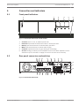
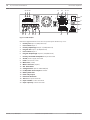
Plena Power Amplifiers
LBB1930/20, LBB1935/20, LBB1938/20, LBB1938/70
en
Installation and Operation manual
Plena Power Amplifiers
Table of Contents | en
3
Table of contents
1
Safety
4
2
About this manual
5
2.1
Manual purpose
5
2.2
Digital document
5
2.3
Intended audience
5
2.4
Alerts and notice signs
5
2.5
Conversion tables
6
2.6
Copyright and disclaimer
6
2.7
Document history
6
3
System Overview
7
3.1
Product range introduction
7
3.2
Power amplifier range
7
4
Installation
8
5
Connection and indicators
9
5.1
Front panel indicators
9
5.2
Rear panel connectors and switches
5.3
Internal setting
11
6
External connections
12
6.1
Connect the back-up power supply
12
6.2
Connecting line input and loop-through
12
6.3
100V slave input
13
6.4
Constant voltage loudspeakers
13
6.5
Low impedance loudspeakers
14
6.6
Priority controlled loudspeaker
15
6.7
Power
15
7
Supervision
16
7.1
Input pilot tone
16
7.2
Battery supervision
16
7.3
Mains supervision
16
8
Operation
17
8.1
Switch ON
17
8.2
Connecting the priority input and using the control terminals
18
9
Maintenance
19
10
Technical data
20
10.1
Electrical
20
10.1.1
Mains voltage
20
10.1.2
Battery voltage
20
10.1.3
Rated power
20
10.2
Performance
20
10.2.1
Signal performance
20
10.2.2
Signal-to-Noise Ratios
20
10.2.3
Line inputs
21
10.2.4
Loudspeaker outputs
21
10.2.5
Power consumption
22
10.3
Mechanical specifications
24
10.4
Environmental conditions
24
Bosch Security Systems B.V.
Installation and Operation manual
9
2014.01 | V1.1 | LBB193x/x0
4
en | Safety
1
Plena Power Amplifiers
Safety
Prior to installing or operating products, always read the Important Safety Instructions which
are available as a separate multilingual document: Important Safety Instructions (Safety_ML).
These instructions are supplied together with all equipment that can be connected to the
mains supply.
Safety precautions
The Power Amplifier designed to be connected to the public distribution network.
–
To avoid any risk of electric shock, all interventions must be carried out with
disconnected mains supply.
–
The ventilation should not be impeded by covering the ventilation openings.
–
Connection of external wiring to this equipment requires installation by qualified
personnel only.
–
The operation must only be performed by qualified personnel.
–
Use the apparatus in a moderate climate.
Caution!
!
These service instructions are for use by qualified service personnel only.
To reduce the risk of electric shock, do not perform any servicing other than that contained in
the operating instructions unless you are qualified to do so.
2014.01 | V1.1 | LBB193x/x0
Installation and Operation manual
Bosch Security Systems B.V.
Plena Power Amplifiers
About this manual | en
2
About this manual
2.1
Manual purpose
5
The purpose of this manual is to provide information required for installing, configuring,
operating and maintaining the Plena Power Amplifier.
The following related documents are available:
2.2
–
Plena Voice Alarm System Operation manual.
–
Plena Voice Alarm System Software manual.
Digital document
This manual is available as a digital document in the Adobe Portable Document Format (PDF).
Refer to the product related information at: www.boschsecurity.com.
2.3
Intended audience
This manual is intended for installers, operators and users of a Plena system.
2.4
Alerts and notice signs
Four types of signs can be used in this manual. The type is closely related to the effect that
may be caused if it is not observed. These signs - from least severe effect to most severe
effect - are:
Notice!
Containing additional information. Usually, not observing a ‘notice’ does not result in damage
to the equipment or personal injuries.
Caution!
!
The equipment or the property can be damaged, or persons can be lightly injured if the alert
is not observed.
Warning!
!
The equipment or the property can be seriously damaged, or persons can be severely injured
if the alert is not observed.
Danger!
Not observing the alert can lead to severe injuries or death.
Bosch Security Systems B.V.
Installation and Operation manual
2014.01 | V1.1 | LBB193x/x0
6
2.5
en | About this manual
Plena Power Amplifiers
Conversion tables
In this manual, SI units are used to express lengths, masses, temperatures etc. These can be
converted to non-metric units using the information provided below.
1 in =
25.4 mm
1 mm =
0.03937 in
1 in =
2.54 cm
1 cm =
0.3937 in
1 ft =
0.3048 m
1m=
3.281 ft
1 mi =
1.609 km
1 km =
0.622 mi
1 kg =
2.2046 lb
1 hPa =
0.0145 psi
Table 2.1: Conversion of units of length
1 lb =
0.4536 kg
Table 2.2: Conversion of units of mass
1 psi =
68.95 hPa
Table 2.3: Conversion of units of pressure
Notice!
1 hPa = 1 mbar
2.6
°F =
9
_
. °C + 32
5
°C =
5
_
. (°F - 32)
9
Copyright and disclaimer
All rights reserved. No part of this document may be reproduced or transmitted in any form by
any means, electronic, mechanical, photocopying, recording, or otherwise, without the prior
written permission of the publisher. For information on getting permission for reprints and
excerpts, contact Bosch Security Systems B.V..
The content and illustrations are subject to change without prior notice.
2.7
Document history
Release date
Documentation version
Reason
2014.01.10
V1.0
1st edition.
2014.01.21
V1.1
2nd edition. Minor technical
data changes.
2014.01 | V1.1 | LBB193x/x0
Installation and Operation manual
Bosch Security Systems B.V.
Plena Power Amplifiers
System Overview | en
3
System Overview
3.1
Product range introduction
7
The Power Amplifier is part of the Plena product range. The Plena product range provides
public address solutions for places where people gather to work, worship, trade, or to relax. It
is a family of system elements that are combined to create public address systems tailored for
virtually any application. The Plena product range includes:
–
Mixers
–
Pre‑amplifiers
–
Power amplifiers
–
Music source unit
–
Digital message manager
–
Feedback suppressor
–
Call stations
–
"All-In-One" system
–
Voice Alarm System
–
Timer
–
Charger
–
Loop amplifier
The various elements are designed to complement each other using matched acoustical,
electrical and mechanical specifications.
All Plena Power Amplifiers in this manual are designed for use in EN54‑16 and EN60849
compliant systems.
3.2
Power amplifier range
The Plena Power Amplifier range consists of the following mono amplifiers:
–
120W LBB 1930/20 (2 units high).
–
240W LBB 1935/20 (2 units high).
–
480W LBB 1938/x0 (3 units high).
In this manual all illustrations show either the LBB 1938/x0 power amplifier that is 3 units
high, the LBB 1930/20, LBB 1935/20 power amplifier that is 2 units high. All connections are
similar between the different power amplifiers. These power amplifiers have 70V and 100V
constant voltage outputs and a low impedance output for 4 or 8 Ohm loudspeakers.
Two inputs, "Priority" and "Program", give priority and controlled outputs. A 100V slave input
gives connection to existing loudspeaker lines. The line inputs are balanced and have a
loop‑through facility. The amplifiers have overload and short‑circuit protection. A temperature
controlled fan and overheat protection gives high reliability. Battery operation with automatic
switchover from the mains supply is available.
Bosch Security Systems B.V.
Installation and Operation manual
2014.01 | V1.1 | LBB193x/x0
8
4
en | Installation
Plena Power Amplifiers
Installation
The power amplifier is intended for tabletop use, however the unit can also be mounted in a
19” rack. For 19" rack installation; use:
–
The 19" rack mounting brackets which come with the product.
–
Standard M6 mounting screws: 16 mm thread depth, 20 mm total length.
The power amplifier has an internal fan regulated to keep the temperature inside the unit
within safe operating conditions.
0 dB
-6 dB
-20 dB
Figure 4.1: Brackets for 19" rack mounting
Notice!
If you install the product into a 19” rack:
- Ensure that it does not exceed the overheating temperature (+45°C ambient).
- Make sure that warm air that is expelled from the side and rear can flow away.
- Ensure sufficient ventilation and enough room, about 10cm / 4” behind the unit for cables
and connections.
- Use the included Bosch 19” mounting brackets (LBC 1901/00) x2.
- Remove the tabletop feet from the bottom of the unit.
2014.01 | V1.1 | LBB193x/x0
Installation and Operation manual
Bosch Security Systems B.V.
Plena Power Amplifiers
Connection and indicators | en
5
Connection and indicators
5.1
Front panel indicators
1
2
3
0 dB
-6 dB
-20 dB
4
5
9
6
Status
Pilot-Tone
B a tte ry
Mains
O v e r he a t
Figure 5.1: LBB 1930/20 LBB 1935/20 and LBB 1938/20
1.
VU meter LED’s for -20, -6, 0dB and power ON.
2.
Pilot‑Tone supervised function that monitors a 20 kHz pilot tone.
3.
Battery supervised function to indicate battery operation.
4.
Mains supervised function to indicate mains supply.
5.
Overheat supervised function to give warning of overheating.
6.
Air inlet cooling is made by forced ventilation from front to back. Amplifiers can be
stacked on top of each other. A supply of cool air from the front is necessary.
5.2
Rear panel connectors and switches
20
19
18
17
Input 1 Input 2 Slave Input
Priority Enable 100V
16
OffOn
Battery
Detection
NO COM NC
NO COM NC
NO COM NC
OffOn
+
-
100V
0
Input 1-Priority
0
70V
0
Rated input
Power : 1600VA
8ohm
8
F701
Loopthrough 2
F702
2..24V GND 2..24V GND 100V
Default Off Default On
Input 2 Program
12
Power
100V
0
70V
0
Direct O utput
Loopthrough 1
Input 2 Enable
2..24V- Enable
0V- Mute
13
Apparatus delivered
connectored for 230V~
230V~
240V~
Input Battery Main Power
Input 1 Priority
S lave Input 100V
14
Fault Relays' Output
Pilot-tone
Detector
Input 1 Priority
2...24V- Input 1
0V- Input 2
15
11
100V/70V
S election (12A)
Priority Only
0
Input 2-Program
No Priority
0
+
-
Priority
10
Priority Controlled Output 24V DC In
100V
0
100V
Input
1
3
4
1 00V
Priority Only
Input
2
0
5
6
0
No Priority
7
8
9
Figure 5.2: LBB 1930/20 LBB 1935/20
Bosch Security Systems B.V.
Installation and Operation manual
2014.01 | V1.1 | LBB193x/x0
10
en | Connection and indicators
Plena Power Amplifiers
20 19 18
17
Loopthrough 1
Pilot-tone
Detector
Input 2 Program
Loopthrough 2
Input 1 Priority
2...24V- Input 1
0V- Input 2
+
-
Input 2 Enable
2..24V- Enable
0V- Mute
+
-
OffOn
0
100V
0
70V
0
0
12
Battery
Detection
NO COM NC
NO COM NC
OffOn
NO COM NC
100V
0
70V
0
8
Apparatus
delivered
connectored
for 230V~
11
8ohm
F701
Input 2-Progr am
F702
Input 1-Priority
Power
Input Battery Main Power
Direct O utput
Slave Input 100V 100V
2..24V GND 2..24V GND 100V
Default Off Default On
15 14
Fault Relays' Output
Input 1 Priority
Input 1 Input 2 Slave Input
Priority Enable 100V
16
100V/70V
Selection (12A)
Rated input
Power : 1600VA
Priority Only
0
No Priority
0
Priority Controlled Output
10
24V DC In
Priority
100V
Input
0V
Priority Only
Input
1
100V
0V
Input
8
No Priority
Output
2
3
4
5
6
7
9
Figure 5.3: LBB 1938/x0
Note that slight deviations from the rear panel layout shown may occur.
1.
Priority line input 1 (XLR/balanced)
2.
Level control input 1
3.
Priority loopthrough output 1 (XLR/balanced)
4.
Program line input 2 (XLR/balanced)
5.
Level control input 2
6.
Program loopthrough output 2 (XLR/balanced)
7.
Priority controlled loudspeaker output terminals
8.
24 Vdc power supply terminals
9.
Earth connection screw
10. Mains fuse (T10A)
11. Mains connector (3-pole)
12. ON - OFF switch
13. Voltageselector (Not on LBB 1938/x0)
14. Loudspeaker direct output terminals
15. Battery detection
16. Fault relay output
17. Pilot-Tone detection
18. 100 V slave input terminals
19. Input 2 enable control terminals
20. Input 1 priority control terminals
2014.01 | V1.1 | LBB193x/x0
Installation and Operation manual
Bosch Security Systems B.V.
Plena Power Amplifiers
5.3
Connection and indicators | en
11
Internal setting
The output voltage of the priority controlled loudspeaker outputs can be set to 70V or 100V. A
high power fuse inside the unit is used as a voltage selector. Insert the high power fuse into
fuse holder F701 for 100V selection (default setting), or into fuse holder F702 for 70V
selection. This selection does not affect the output voltage of the loudspeaker direct outputs.
F701
100V
F702
70V
Figure 5.4: Internal fuse setting LBB 1930/20, LBB 1935/20, LBB 1938/x0
See also
–
Bosch Security Systems B.V.
Rear panel connectors and switches, page 9
Installation and Operation manual
2014.01 | V1.1 | LBB193x/x0
12
en | External connections
Plena Power Amplifiers
6
External connections
6.1
Connect the back-up power supply
The power amplifier has a 24VDC input (8) screw terminal to connect a back-up power supply.
You must connect an earth (9) to the unit to increase the electrical stability of the system.
elays'
O utp
t B atte
ry
NC NO
C OM
ut
Main
Power
Batter
Detect y
ion
NC NO
COM
NC
Input
1
P riority Input 2 S
E na ble lave Input
100V
App
connecaratus deliv
ered
tore
23 0V~ d for 230
V~
24 0V~
Off On
Dir ect
10 0V
70 V
R elays'
Input
Outpu
B attery
t
Main Power
B attery
Detectio
n
Off On
NO C
OM
2-P rogra
m
NC NO
C OM
NC NO
COM
NC
Apparatus
connector delivered
230V~ ed for 23 0V~
240V~
O ff O
n
Direct
100 V
0
Power
O utput
70V
0
100V
0
70V
0
8
8ohm
8
Priority
Input
R ated
input
Power
: 160
0VA
100V/70
V
Selectio
n (12A)
100V
0
F702
12 VD
Pilot-ton
Detectoe
r
0
Input
100V
0
70V
0
F702
-
0
riority
Input
0
F701
100V
Input
0
8ohm
Priority
Fault
2. . 24V
Defa G ND 2. . 24V
ult O
ff Defa G ND 100V
ult O
n
1-P
+
+
100V
ut
F701
0
Input
1 Priority
Loopthrough
1
Input
2 Program
Loopthrough
2
Input
1 Priority
2...24V0V- InputInput 1
2
Input
2
2..24V- Enable
Enable
0V- Mute
Slave
Input
100V
Pow er
O utp
100V/70V
Selection
1 00V
R ated
Power
(12A)
Contro
lled O
input
: 1600VA
Priority
Only
0
utput
0
No Priority
0
Priority
24V DC
In
Priority
Only
0
Controlle
No Priority
0
d O utp
ut 24
10 0V
V DC
In
0
Priority
+
-
+
C
12 VD
C
Figure 6.1: Back‑up power supply
6.2
Connecting line input and loop-through
The power amplifier has a balanced line input for connection to a pre‑amplifier or a mixer. Use
the loop‑through connection to connect the power amplifier to another power amplifier if
more power is needed. Each power amplifier must be connected to its own set of
loudspeakers. Do not connect power outputs to each other.
Use program line input 2 (4) and line loop‑through 2 (6) for normal operation without priority.
T el/E
/Line
MG
T rigger
1
T rigger
2
0
1.Aud
2.0V io+
5.Allc
all
3.Aud
6.Da
ta4.24V io- 7.Da
ta+
d.c.
8.C hs.G
/Line
33
5 5
P C Audio
ND
1
2
In
R S 232
Zone
CD
5
L
4
Zone
2
6
8
5
2
R
1
-
C all
Active
G ND
1
3
G ND
1
-
+
100V
2
3
4
Mas terO
6
Aux
+
7
3
Zone
Appa
ratus
delive
conne
red
cted
for 230V
In
- 115V - 230V
In
100V
Zone
0
Zone
100V
3
Zone
0
100V
4
0
DC Out
0
DC In
100V
0
-
2
Out
100V
C all
0
1
ut
100V
0
100V
0
+24V
-
+24V
-
R ated
input
P ower
: 50V
A
T 1.0AL
250V
Warni
ng
T his
4
appara
tus mus
t
be earthe
d
6
LBB 1
938/10
LBB 1938/1
Ple
Max. output wer
Amplifier
power
R ated
720W
230V~ utp t ow
r 180W
,50/
N 6
NL-4827HG
-10
Made in
A035413
Design
The & Quality
er an
Plena
8900
480W
193 81001
Max. output Power
Amplifier
power
R ated
720W
output
230V~
power
,50/60Hz 180W
S /N.
A035413
Inpu t
1
P riori Inpu t 2 S
ty E na
lave
ble 100V Inpu t
Design
& Quality
The Netherlands
Input
1 Priority
Loopthro
ugh 1
Input
2 Program
Loopthro
ugh 2
Input
1 Priority
2...24V0V- InputInput 1
2
Input
2
2..24V- Enable
Enable
0V- Mute
Slave
Input
100V
+
+
100V
2. . 24V
Defa G ND 2. . 24V
ult O
ff Defa G ND 100V
ult O
n
1-P
Inpu t
riority
Pilot-tone
Detector
B attery
Main Powe
r
B attery
Detection
O ff O
n
0
NO C
O M NC
0
Inpu t
2-P rogr
am
NO C
O M NC
NO C
OM
NC
Appar
conne atus deliver
ctored
ed
230V~ for 230V~
240V~
Off O
n
Dire ct
100V
0
70V
100V
Inpu t
1
P riori Inpu t 2 S
ty E na
lave
ble 100V Inpu t
2. . 24V
Defa G ND 2. . 24V
ult O
ff Defa G ND 100V
ult O
n
1-P
Inpu t
riority
Pilot-tone
Detector
0
8
8ohm
(12A)
R ated
input
Power
: 16 00V
A
Inpu t
Priority
Only
0
O utpu
t 24V
1 00V
DC In
0
No Priority
0
Priority
Input
NO C
O M NC
2-P rogr
am
B attery
NO C
OM
t
Main Powe
r
B attery
Detection
NC NO
COM
NC
Appar
conne atus deliver
ctored
ed
230V~ for 230V~
240V~
O ff O
n
Dire ct
100V
0
Powe
O utpu
70V
0
Inpu t
Priority
Controlle
d
10 0V
0
r
t
100V
0
70V
0
8
8ohm
F702
100V/70V
Selection
Fault R
elays'
O utpu
O ff O
n
0
Inpu t
r
F701
0
100V
N663
NL-4827HG
-10
0
100V
0
70V
0
F702
Inpu t
Input
+
+
-
t
Priority
Controlle
d
10 0V
Slave
Powe
O utpu
F701
Inpu t
Input
1 Priority
Loopthro
ugh 1
Input
2 Program
Loopthro
ugh 2
Input
1 Priority
2...24V0V- InputInput 1
2
Input
2
2..24V- Enable
Enable
0V- Mute
Fault R
elays'
Output
Input
Made in C hina
14
100V/70V
Selection
(12A)
R ated
input
Power
: 1600V
A
Priority
Only
0
Output
24V DC
1 00V
In
0
No Priority
0
Priority
Figure 6.2: Line input and loop‑through
2014.01 | V1.1 | LBB193x/x0
Installation and Operation manual
Bosch Security Systems B.V.
Plena Power Amplifiers
6.3
External connections | en
13
100V slave input
The power amplifiers have a 100V slave input (18) that can be connected to an existing 100V
loudspeaker line. In this way it is easy to connect an additional power amplifier on a remote
location for more output power. The 100V input is not affected by the control terminals for
input 1 priority (20) or input 2 enable (19).
0
LBB 1938/10
Input 1 Input 2 S lave Input
P riority E na ble 100V
8900 193 81001
Plena 480W P ower Amplifier
Max. output power 720W
Rated output power 180W
230V~,50/60Hz
S/N.
A035413
N663
NL-4827HG-10
Fault Relays' Output
Pilot-tone
Detector
Made in China
2. . 24V G ND 2. . 24V G ND 100V
D e fa ult O ff D e fa ult O n
Design & Quality
The Netherlands
OffOn
Battery
Detection
NO COM NC
NO COM NC
NO COM NC
OffOn
Loopthrough 1
Loopthrough 2
+
-
Input 2 Enable
2..24V- Enable
0V- Mute
+
-
Input 1-P r iority
0
70V
0
8
Rated input
Power : 1600VA
8ohm
F701
Input 2 Program
Input 1 Priority
2...24V- Input 1
0V- Input 2
100V
0
F702
2. . 24V G ND 2. . 24V G ND 100V
D e fa ult O ff D e fa ult O n
Power
100V
0
70V
0
D ire ct O utput
Input 1 Priority
S lave Input 100V
Apparatus delivered
connectored for 230V~
230V~
240V~
Input Battery Main Power
100V/70V
S election (12A)
Priority Only
0
Input 2-P rogra m
No Priority
0
Priority
Priority Controlled Output 24V DC In
100V
0
100V
Input
Input
0
Priority Only
100V
0
No Priority
Figure 6.3: 100 V slave input
Notice!
If the 100V slave input is used, and the 0V and 100V are incorrectly connected, no pilot tone
is detected on the power amplifier. Refer to section Input pilot tone, page 16, for more
information.
6.4
Constant voltage loudspeakers
The power amplifier can drive 100V constant voltage loudspeakers at full power (100V) or half
power (70V). Connect the loudspeakers in parallel and check the loudspeaker polarity for inphase connection. The summed loudspeaker power should not exceed the rated amplifier
power.
Bosch Security Systems B.V.
Installation and Operation manual
2014.01 | V1.1 | LBB193x/x0
14
6.5
en | External connections
Plena Power Amplifiers
Low impedance loudspeakers
Connect low impedance loudspeakers to the 8 ohm/0 terminals. This output can deliver the
rated output power into an 8 ohm load. Connect multiple loudspeakers in a series/parallelarrangement to make the combined impedance 8 ohm or higher. Check the loudspeaker
polarity for in‑phase connection.
8 Ohm
100 V
8 Ohm
8 Ohm
8 Ohm
8 Ohm
4 Ohm
70 V
4 Ohm
8 Ohm
Design
& Q uality
The Netherlands
N6 63
NL-4827HG
-10
Input
1 Priority
Loopthrou
gh 1
Input
2 Program
Loopthrou
gh 2
Input
1 Priority
2...24V0V- InputInput 1
2
Input
2
2..24V- Enable
Enable
0V- Mute
Slave
Input
100V
+
+
100V
Made in C hina
LBB 1938/10
Plena
8900
480W
193 81001
Max. output Power
Amplifier
power
R ated
720W
output
230V~
power
,50/60Hz 180 W
S /N.
A035413
Inpu t
1
P riori Inpu t 2 S
ty E na
lave
ble 100V Inpu t
2. . 24V
Defa ultG ND 2. . 24V
O
G
Inpu t ff Defa ult ONDn 100V
1-P
riori ty
Pilot-tone
Detector
Fault Re
lays'
Input
O utpu
t
B attery
Main Powe
NO C
OM
Inpu t
2-P rogr
am
NC NO
C OM
r
B attery
Detection
O ff O
n
0
0
NC NO
COM
NC
Appara
connec tus deliver
tored
ed
230V~ for 230V~
240V~
Off O
n
Dire ct
100V
0
Powe
O utpu
70V
0
100V
0
70V
0
8
Priority
Controlle
100V
d
0
F702
F701
Inpu t
r
t
8ohm
Inpu t
100V/70V
Selection
(12A)
R ated
input
Power
: 1600V
A
Priority
Only
0
O utpu
t 24V
DC In
0
No Priority
0
Priority
1 00V
D ire ct O utput
100V
0
70V
0
8
Priority Controlled Output 24V DCIn
100V
0
Priority Only
100V
0
No Priority
Priority Only No Priority
Figure 6.4: Priority input and control terminals
2014.01 | V1.1 | LBB193x/x0
Installation and Operation manual
Bosch Security Systems B.V.
Plena Power Amplifiers
6.6
External connections | en
15
Priority controlled loudspeaker
Loudspeakers connected to the Priority Only output will receive only audio signals with
priority, like calls from a call station.
Loudspeakers connected to the No Priority output will receive all audio signals, such as music,
but no signals with priority, like calls.
6.7
Power
Use the mains lead to connect the amplifier to the power supply.
Plena
8900
480W
193 81001
Max. output Power
Amplifier
power
R ated
720W
output
230V~
power
,50/60Hz 180W
S /N.
A035413
Design
& Q uality
The Netherlands
Input
t B att
ery
1-P riority
Pilot-ton
Detectoe
r
Relays
Input
' Outpu
B attery
t
Main Power
B attery
Detectio
n
O ff On
0
NO C
OM
Input
2-P rogra
m
NC NO
C OM
NC NO
COM
NC
Apparatus
connector delivered
230V~ ed for 23 0V~
240V~
O ff On
Direct
100V
0
Power
O utput
70V
0
100V
0
70V
0
8
8ohm
F702
NC
Input
1
P riority Input 2 S
E na ble lave Input
100V
2. . 24V
Defa G ND 2. . 24V
ult O
ff Defa G ND 100V
ult O
n
Input
Input
100V/70V
Selection
Input
App
connecara tus deliver
tor
ed
23 0V~ ed for 230
V~
240 V~
Off On
Di re ct
10 0V
0
O utpu
70 V
Contro
lled O
1 00V
input
: 1600VA
Priority
Only
0
utput
0
No Priority
0
Priority
24V DC
In
t
0
100V
0
70V
0
8
Control
led
F702
F701
0
0
Powe
r
8ohm
Priority
10 0V
10 0V
R ated
Power
(12A)
Priority
B attery
Detec
tion
NC NO
COM
-10
Fault
+
+
100V
0
Main Po
wer
F701
NC NO
C OM
N663
NL-4827HG
1 Priority
Loopthrough
1
Input
2 Program
Loopthrough
2
Input
1 Priority
2...24V0V- InputInput 1
2
Input
2
2..24V- Enable
Enable
0V- Mute
Slave
Input
100V
Outp ut
Made in C hina
LBB 1
938/10
elays'
100V/7
0V
Selec
tion (12A)
Rated
input
Powe
r : 1 600
VA
Priorit
y Only
0
Outp ut
10 0V
0
No Priorit
y
0
Priorit
y
Line
fus e
24 V DC
T10In
L2 50
V
Figure 6.5: Mains lead
Bosch Security Systems B.V.
Installation and Operation manual
2014.01 | V1.1 | LBB193x/x0
16
7
en | Supervision
Plena Power Amplifiers
Supervision
Supervision is provided for:
–
Pre‑amplifier and power amplifier function
–
Battery and mains supervision
Relays are provided on the rear panel for the each supervised function and are normally
energized (fail‑safe). Each relay has 3 contacts, normally open, common and normally closed.
If an application does not need supervision, the indicators on the front panel can be set to
“OFF” with the switches next to each relay output. The relays always function and are
independent of the indicator switch setting.
7.1
Input pilot tone
The Plena Voice Alarm System uses a pilot tone of 20kHz at -20dBV to supervise the preamplifier, the connections between the pre‑amplifier and the power amplifier and function of
the power amplifier. If the input signal from the pre‑amplifier stops, the mains and battery fail,
or the power amplifier stops for any other reason, the pilot‑tone stops, the pilot‑tone fault
indication shows on the front panel and a signal is given on the Input fault relay. If the power
amplifier stops through overheat, then the overheat indicator shows on the front panel, the
signal is given on the Input fault relay.
The pilot‑tone detection indicator can be set to “ON” or “OFF” with the pilot‑tone detection
switch (17), see Rear panel connectors and switches, page 9. The pilot‑tone indicator on the
front panel is set to “OFF”, but the fault relay switch still functions.
7.2
Battery supervision
The power amplifier supervises the availability of the back‑up power supply.
If the battery supply fails the battery fault indication shows on the front panel and the battery
fault relay switches over.
The battery supervision indicator can be set to “ON” or “OFF” with the battery detection
switch (15), Rear panel connectors and switches, page 9. The battery indicator on the front
panel is set to “OFF”, but the fault relay switch still functions.
The amplifier will work between 20VDC and 26.5VDC. Below 20VDC the amplifier will shut
down if the mains is not present.
The amplifier will automatically switch from primary power (mains) to backup power (24VDC),
this changeover is automatic. During switch over a glitch can be heard in the audio signal,
typically this lasts less than 1 second, maximum 2 seconds duration.
7.3
Mains supervision
The power amplifier supervises the availability of the mains supply. If the mains supply fails
(falls below the threshold of -20%), and the back‑up power supply takes over, the fault relay
moves to the NOK position. A mains fault indication shows on the front panel and a fault state
is given by the mains fault relay.
2014.01 | V1.1 | LBB193x/x0
Installation and Operation manual
Bosch Security Systems B.V.
Plena Power Amplifiers
Operation | en
8
Operation
8.1
Switch ON
17
Put the power switch on the rear of the power amplifier in the “I” position.
Plena
8900
480W
193 81001
Max. output Power
Amplifier
power
R ated
720W
output
230V~
power
,50/60Hz 180W
S /N.
A035413
Design
& Q uality
The Netherlands
Input
1-P riority
Pilot-ton
Detectoe
r
Relays
Input
' Outpu
B attery
t
Main Power
B attery
Detectio
n
O ff On
0
NO C
OM
Input
2-P rogra
m
NC NO
C OM
NC NO
COM
NC
Apparatus
connector delivered
230V~ ed for 23 0V~
240V~
O ff On
Direct
100V
0
Power
O utput
70V
0
100V
0
70V
0
8
8ohm
F702
Input
100V/70V
Selection
Input
App
connecara tus deliver
tor
ed
23 0V~ ed for 230
V~
240 V~
Off On
Di re ct
10 0V
0
70 V
0
100V
0
70V
0
8
Control
led
F702
0
Contro
lled O
1 00V
input
: 1600VA
Priority
Only
0
utput
0
No Priority
0
Priority
24V DC
In
t
F701
Priority
0
Powe
r
O utpu
8ohm
10 0V
10 0V
R ated
Power
(12A)
Priority
B attery
Detec
tion
NC
Input
1
P riority Input 2 S
E na ble lave Input
100V
2. . 24V
Defa G ND 2. . 24V
ult O
ff Defa G ND 100V
ult O
n
Input
0
Main Po
wer
NC NO
COM
-10
Fault
+
+
100V
F701
NC NO
C OM
N663
NL-4827HG
1 Priority
Loopthrough
1
Input
2 Program
Loopthrough
2
Input
1 Priority
2...24V0V- InputInput 1
2
Input
2
2..24V- Enable
Enable
0V- Mute
Slave
Input
100V
Outp ut
t B att
ery
Made in C hina
LBB 1
938/10
elays'
100V/7
0V
Selec
tion (12A)
Rated
input
Powe
r : 1 600
VA
Priorit
y Only
0
Outp ut
10 0V
0
No Priorit
y
0
24 V
LinePriority
fus e
T10In
DC
L2 50
V
Figure 8.1: Power switch and power connection
1
2
0 dB
-6 dB
-20 dB
3
4
5
6
Status
Pilot-Tone
B a tte ry
Mains
O v e r he a t
Figure 8.2: LBB 1930/20 LBB 1935/20, LBB 1938/x0
If mains power or back‑up power is available, the VU‑bar (1) on the front of the power
amplifier is lit and shows the output level of the amplifier.
If the internal temperature reaches a critical limit due to poor ventilation or overload, an
overheat protection circuit switches “OFF” the power stage. The overheat indicator (5) shows
on the front panel and the Input fault relay switches over if the power stage is switched “OFF”
by the overheat protection circuit. The Battery operation indicator (3) lights up if the mains
power supply is failing and the back‑up battery is in use.
Bosch Security Systems B.V.
Installation and Operation manual
2014.01 | V1.1 | LBB193x/x0
18
8.2
en | Operation
Plena Power Amplifiers
Connecting the priority input and using the control terminals
The power amplifier is provided with a balanced priority input (Input 1‑Priority) to connect to
a pre‑amplifier or mixer.
Refer to figure 5.2 and 5.3. Apply a control voltage of 2...24V to the input 1 priority control
terminals (20) to switch “ON” the priority input (1) and mute the program input (4). A local
music source can be connected to the program input and a remote emergency system to the
priority input. The emergency source must be able to supply the 2…24V control voltage to
override the local music source. The program input can be remotely controlled by using a
switch that is connected to the input 2 enable control terminals (19). Closing the switch
forces the input to <2V and disables the program input.
Application example of the use of the power amplifier control terminals
You can use up to 6 power amplifiers in combination with the Plena LBB1925/10 System
Pre‑amplifier to build a powerful multi-zone sound system. Zone switching of BGM and calls is
done via the LBB1925/10 zone relays in combination with the power amplifier control
terminals. The LBB1925/10 controls the background music by distributing 24VDC via the
music zone relays to the input 2 enable control terminals (19).The LBB1925/10 controls the
calls by distributing 24VDC via the call zone relays to the input 1 priority control terminals
(20). Each power amplifier serves one loudspeaker zone. Each zone can be “OFF”, or receive
music or a call.
LBB1925/10
Trigger 1
Tel/EMG
Trigger 2
Apparatus delivered
connected for 230V-
LBB1925/10
890019251005
115/230V~,50/60Hz
No.
115V
230V
0
5. Allcall
6.DataPCAudoln
7.Data+
8.Chs.GND
1. Audio+
2.0V
3.Audio4.24Vd.c.
/Line
CD
RS232
A ux
L
/Line
+
2
-
GND
GND
1
1
3
R
7
LBB 1938/10
Input 1 Input 2 S lave Input
P riority E na ble 100V
A035413
N663
NL-4827HG-10
Design & Quality
The Netherlands
OffOn
Loopthrough 1
NO COM NC
100V 0
Rated Input
Power : 50VA
T0.5L 250V
+24VWarning
This apparatus must be earthed
Power
100V
0
70V
0
LBB 1938/10
0
70V
0
8
Rated input
Power : 1600VA
8ohm
100V/70V
S election (12A)
Priority Only
0
Input 2-P rogra m
No Priority
0
+
-
Priority
Priority Controlled Output 24V DC In
0
Input 1 Input 2 S lave Input
P riority E na ble 100V
8900 193 81001
A035413
N663
NL-4827HG-10
Fault Relays' Output
Pilot-tone
Detector
Design & Quality
The Netherlands
OffOn
Loopthrough 1
2. . 24V G ND 2. . 24V G ND 100V
D e fa ult O ff D e fa ult O n
Input 2 Program
Input 1 Priority
2...24V- Input 1
0V- Input 2
Input 2 Enable
2..24V- Enable
0V- Mute
S lave Input 100V
Apparatus delivered
connectored for 230V~
230V~
240V~
Input Battery Main Power
Battery
Detection
NO COM NC
NO COM NC
NO COM NC
OffOn
+
-
Input 1-P r iority
100V
0
0
70V
Power
100V
0
70V
0
D ire ct O utput
Input 1 Priority
Loopthrough 2
100V
+24V-
0
8
Rated input
Power : 1600VA
8ohm
F701
Input 1-P r iority
100V 0
F702
+
-
100V 0
Out
Plena 480W P ower Amplifier
Max. output power 720W
Rated output power 180W
230V~,50/60Hz
S/N.
OffOn
100V
0
100V 0
MasterOut
Apparatus delivered
connectored for 230V~
230V~
240V~
Battery
Detection
NO COM NC
1
4
100V 0
2
Input Battery Main Power
NO COM NC
100V 0
6
8
5
F701
Loopthrough 2
Input 2 Enable
2..24V- Enable
0V- Mute
3
4
2
F702
2. . 24V G ND 2. . 24V G ND 100V
D e fa ult O ff D e fa ult O n
Input 2 Program
S lave Input 100V
1
5
D ire ct O utput
Input 1 Priority
Input 1 Priority
2...24V- Input 1
0V- Input 2
3
Fault Relays' Output
Pilot-tone
Detector
Made in China
8900 193 81001
Plena 480W P ower Amplifier
Max. output power 720W
Rated output power 180W
230V~,50/60Hz
S/N.
3
5
100V 0
2
Made in China
14
100V 0
+
3
100V/70V
S election (12A)
Priority Only
0
Input 2-P rogra m
No Priority
0
+
-
Priority
Priority Controlled Output 24V DC In
100V
0
100V
Input
Input
0
Priority Only
1 00V
0
No Priority
100V
Input
Input
0
Priority Only
1 00V
0
No Priority
Figure 8.3: LBB1925/10 and power amplifier control terminals example
2014.01 | V1.1 | LBB193x/x0
Installation and Operation manual
Bosch Security Systems B.V.
Plena Power Amplifiers
9
Maintenance | en
19
Maintenance
The units require minimum maintenance, however to keep the units in good condition, the
following tasks should be carried out.
–
Clean the units:
–
–
Periodically clean the units with a damp, lint-free cloth.
Clean the air inlets:
–
The units can collect dust from the operation of the internal fans. The air inlets of the
units should therefore be cleaned on a yearly basis.
–
Periodically check unit connections and grounding:
–
To ensure that all cable connections to the units are secure.
–
The ground (Protective Earth) connection of the system components.
Warning!
!
Dangerous mains voltages are present inside the units. Disconnect the main power supply
before doing any maintenance tasks.
Bosch Security Systems B.V.
Installation and Operation manual
2014.01 | V1.1 | LBB193x/x0
20
en | Technical data
Plena Power Amplifiers
10
Technical data
10.1
Electrical
10.1.1
Mains voltage
10.1.2
LBB 1930/20 LBB 1935/20
230 / 115 VAC , ± 10%, 50 – 60 Hz
LBB 1938/20
230 VAC, 50 – 60 Hz
LBB 1938/70
110 VAC, 50 – 60 Hz
Battery voltage
Battery voltage
10.1.3
24V DC, 20 - 26.5 V
Rated power
LBB 1930/20
400 VA
LBB 1935/20
960 VA
LBB 1938/x0
1600 VA
10.2
Performance
10.2.1
Signal performance
Frequency response
50 Hz - 20 kHz (+1/-3 dB @ -10 dB ref. rated
output)
Distortion
10.2.2
<1% @ rated output, 1 kHz
Signal-to-Noise Ratios
LBB 1930/20
> 80 dB
LBB 1935/20
> 85 dB
LBB 1938/x0
> 90 dB
2014.01 | V1.1 | LBB193x/x0
Installation and Operation manual
Bosch Security Systems B.V.
Plena Power Amplifiers
10.2.3
Technical data | en
21
Line inputs
3 pin XLR balanced
Sensitivity
1V
Impedance
20 kohm
CMRR
> 40 dB (50 Hz - 20 kHz)
100V input, screw unbalanced
10.2.4
Sensitivity
100 V
Impedance
330 kohm
Loudspeaker outputs
Line loopthrough output (3 pin XLR balanced)
Nominal level
1V
Impedance
Direct connection to line input
Maximum rated output power - 70/100V output
LBB 1930/20
240 W
LBB 1935/20
240 W
LBB 1938/x0
480 W
8 Ohm outputs
LBB 1930/20
31 V / 120 W
LBB 1935/20
44 V / 240 W
LBB 1938/x0
62 V / 480 W
Power reduction@24 V battery operations
Reference rated power
-1 dB (LBB 1935/20)
-2 dB (LBB 1930/20 LBB 1938/x0)
Bosch Security Systems B.V.
Installation and Operation manual
2014.01 | V1.1 | LBB193x/x0
22
en | Technical data
10.2.5
Plena Power Amplifiers
Power consumption
Power (mains)
LBB 1930/20
Unit
Full power
274
Watt
- 3 dB
193
Watt
- 6 dB
143**
Watt
10V
41
Watt
Idle
18
Watt
Full power
7
Amp
- 3 dB
6
Amp
- 6 dB
4**
Amp
10V
1
Amp
Idle
0.1
Amp
Full power
168
Watt
- 3 dB
144
Watt
- 6 dB
96
Watt
10V
24
Watt
Idle
2.4
Watt
Power (mains)
LBB 1935/20
LBB 1938/x0
Unit
Full power
451
987
Watt
- 3 dB
340
715
Watt
- 6 dB
244**
508**
Watt
10V
55
113
Watt
Idle
16
25
Watt
Full power
12
32
Amp
- 3 dB
11
26
Amp
- 6 dB
8**
18**
Amp
10V
2
4
Amp
Idle
0.3
1
Amp
Full power
288
768
Watt
Backup power
(24VDC)
Backup power
(24VDC)
2014.01 | V1.1 | LBB193x/x0
Installation and Operation manual
Bosch Security Systems B.V.
Plena Power Amplifiers
Technical data | en
Power (mains)
LBB 1935/20
LBB 1938/x0
Unit
- 3 dB
264
624
Watt
- 6 dB
192
432
Watt
10V
48
96
Watt
Idle
7.2
24
Watt
23
* Output limited to -3dB
** Corresponds to pink noise and voice on full power
*** Output limited for sine wave signal to -3dB
Bosch Security Systems B.V.
Installation and Operation manual
2014.01 | V1.1 | LBB193x/x0
24
en | Technical data
10.3
Plena Power Amplifiers
Mechanical specifications
Dimensions
Width
19”
Height (including feet)
2 Unit models: 100 mm
3 Unit models: 145 mm
Depth
2 Unit models: 250 mm
3 Unit models: 370 mm
19" Mounting brackets
Included
Weight
10.4
LBB 1930/20
10.5 kg
LBB 1935/20
12.5 kg
LBB 1938/x0
25.0 kg
Environmental conditions
Operating temperature range
-10 to +55°C
Storage temperature range
-40 to +70°C
Relative humidity
< 95%
EMC emission
According to EN55103‑1
EMC immunity
According to EN55103‑2
Acoustic noise level of fan
< 45 dB SPL @ 1m at maximum speed
2014.01 | V1.1 | LBB193x/x0
Installation and Operation manual
Bosch Security Systems B.V.
Bosch Security Systems B.V.
Torenallee 49
5617 BA Eindhoven
The Netherlands
www.boschsecurity.com
© Bosch Security Systems B.V., 2014